

Page 1
OPERATING INSTRUCTIONS
LEEB 4 / 5 LT
READ CAREFULLY PRIOR TO STARTING UP!
KEEP OPERATING INSTRUCTIONS IN A SAFE PLACE!
ART.:
ISSUE:
80900208
03/2016
Page 2

EC Declaration of Conformity
exchangeable equipment
(Directives 2006/42/EC and 2009/127/EC)
The manufacturer HORSCH LEEB Application Systems GmbH
Plattlinger Str. 21
D-94562 Oberpöring (Germany)
hereby declares, that the product,
Designation of machine: trailed crop protection device
Machine type: HORSCH LEEB 4 / 5 / 6 LT from chassis number: 36721250
this declaration refers to, conforms with all relevant fundamental health and safety requirements
of the EC directive 2006/42/EC and 2009/127/EC.
For proper implementation of the heath and safety requirements mentioned in the EC-directive,
the following standards and technical specications have been used:
EN ISO 4254-1 :05-2011
EN ISO 4254-6 :10-2011
EN ISO 12100 :03-2011
Documentation Representative:
Manfred Köbler
HORSCH Maschinen GmbH
Sitzenhof 1
D-92421 Schwandorf
Oberpöring, 10.02.2016
Place and date ____________________
Theodor Leeb
(CEO)
Page 3

Vehicle handover certicate
Preparation of vehicle by customer service workshop carried out on Signature
Check oil level, correct if necessary:
Hydraulic oil circuits (PTO-shaft pump)
Lubricate vehicle according to lubrication plan, oil joints
Check Ackerman steering
Check tyre pressure
Check wheel nuts for tight t
Check the electric system
Check the error log
Brake test
Explanations during vehicle handover
Raise the attention for the safety notes in the operating
instructions
Inform about the necessity to comply with country specic
regulations concerning speed and trailer brake systems
Explain the following functional features in detail and
demonstrate their operation:
Operating controls, multiple display, commissioning,
connecting, parking, fault output, code table
Notes on customer service and maintenance
Handover of vehicle accessories
Handover performed:
Page 4

Page 5

Acknowledgement of receipt
No right to claim warranty if this acknowledgement of receipt has not been returned!
* Mandatory eld
To
Dealer
Cust. No.: .................................................
Company ..................................................*
Street: ..... ................................................. *
ZIP-Code: ................................................*
Place: .......................................................*
Country: ................................................... *
Machine type: ..........................................*
Serial number: ..........................................*
Service engineer
Name: ...................................................... *
First name: ...............................................*
Customer I:
Name/company: ......................................*
Name of contact: .....................................*
First name of contact: .............................. *
Road: ....................................................... *
ZIP-Code: ................................................*
Place: .......................................................*
Country: ................................................... *
Phone ......................................................*
Fax: ..........................................................
E-Mail: ......................................................*
Phone: .....................................................
Fax: ..........................................................
E-Mail: ......................................................
New machine sold to nal customer - Initial use*
Customer's machine - Relocation*
Demonstration machine - Initial use*
Demonstration machine - Relocation*
Demonstration machine sold to nal customer - Use*
Customer II:
Name/company: ......................................*
Name of contact: .....................................*
First name of contact: .............................. *
Road: ....................................................... *
ZIP-Code: ................................................*
Place: .......................................................*
Country: ................................................... *
Phone ......................................................*
Fax: ..........................................................
E-Mail: ......................................................*
"
I hereby conrm the receipt of the operating instructions and spare parts list for the machine specied above.
I have been instructed by an authorized dealer or a Service Engineer from HORSCH in the operation and functions as well as the safety related requirements of the machine.
I am aware, that the right to claim warranty will only be eective, if this form is returned to the
responsible dealer or handed over to the Service Engineer, properly completed immediately after
initial instruction.
........................................................................*
Place, date of initial instruction
........................................................................*
Signature of buyer
Page 6

Page 7

- Translation of the Original Operating Instructions -
Machine Identication
The corresponding data is to be entered into the list below upon receiving the machine:
Serial number: ..................................................
Machine type: ...................................................
Year of construction: ........................................
Initial installation: ..............................................
Fittings: .............................................................
..........................................................................
..........................................................................
..........................................................................
Publication date of Operation Manual: 03/2016
Latest change:
Address of Retailer: Name: ......................................................................
Road: ......................................................................
Town/City: ......................................................................
Tel.: ......................................................................
Customer No.:
Retailer: ......................................................................
Address of manufacturer: HORSCH LEEB Application Systems GmbH
Plattlinger Str. 21
D- 94562 Oberpöring (Germany)
80900208 LEEB 4/5 LT en
Kd. Nr.: HORSCH: ......................................................................
Page 8

Foreword
Please note:
Dear Customer,
Thank you for the trust in us you have expressed
by buying this machine.
In order to be able to use the trailed crop protection sprayer to your full advantage, you should
read these operating instructions with utmost
attention before you use the machine.
These operating instructions contain important
information for the proper use and the safe operation of the machine. By purchasing the crop
protection sprayer you have acquired a quality
product from HORSCH LEEB AS.
The LT trailed crop protection sprayer is a machine sprayer for the placing of crop protection
agents and liquid fertiliser in compliance with the
statutory directives for soil cultures.
The contents is structured in such a way that
you will be informed in detail about the required
activities in compliance with the work-related
sequence.
The manual provides you with comprehensive
notes and information concerning maintenance,
safe use of the machine, safe working methods,
special precautions and available accessories.
Compliance with these notes and information is
necessary, important and useful for operational
safety, reliability and conservation of value of the
crop protection sprayer.
Always keep these operating instructions with
the crop protection sprayer. The operating instructions are a component part of your machine.
HORSCH LEEB AS will not assume liability
for any damage or malfunctions resulting from
failure to comply with the operating instructions.
Upon delivery of the machine check for transport
damage or missing parts! Check the delivered
machine for completeness against the delivery
note, including optional equipment you have
ordered. Only immediately raised claims will
lead to compensation!
The operating instructions must be read and
strictly adhered to by all persons working on or
with the machine e.g.:
• Operation (including preparation, fault recti-
cation during work, care)
• maintenance (maintenance and inspection)
• Transport
You receive an acknowledgement of receipt
together with the operating instructions. The
trained personnel of our service and sales partners will train and instruct you in the operation
and care of your machine. After this you or the
sales or service partner should return the receipt
back to HORSCH. This conrms your formal
acceptance receipt of the machine.
The warranty period starts with the date of
delivery.
Only operate the machine after you have been
instructed and in full compliance with these operating instructions. This crop protection sprayer
must only be used by persons who are familiar
with the machine and have been informed about
any possible dangers that may arise from the
machine.
Strictly follow the safety notes! Follow also the
applicable accident prevention regulations as
well as other generally recognised safety, occupational heath and road trac related regulations.
8
Page 9

Any information, illustrations and technical
specications in these operating instructions
are up-to-date at the time of publishing. We, at
any time, reserve the right for design changes,
technical and formal alterations to our products
for the purpose of improvement or to meet
changed legal regulations, without notication.
We will, of course, make up-to-date data available.
Any directions given in these operating instructions always refer to the travel direction of the
machine.
The illustrations in these operating instructions
show dierent versions of the implement and
dierent equipment variants.
Service
The company HORSCH LEEB AS would be
pleased, if your machine and our services would
meet your expectations.
If you encounter any problems, please feel free
to contact your sales partner.
The service sta of our sales partners and the
service employees at Horsch will always be
available for assistance.
In order to be able to solve technical problems
as quickly as possible, we ask you kindly to
support us.
Please help the service personnel by providing
the following information to avoid unnecessary
queries.
• Customer number
• Name of customer representative
• Name and address
• Machine model and serial number
• Purchasing date and operating hours or area
performance
• Type of problem
Compensation claims for damages which have
not been caused by the machine, are excluded.
This also means that any liability for consequential damages caused by travel and operating
faults is excluded.
Warranty claim processing
Warranty claim forms must be submitted through
your local HORSCH sales partner to the Service
Department of HORSCH LEEBG AS GmbH.
HORSCH LEEB Application Systems GmbH
Plattlinger Str. 21
D-94562 Oberpöring
Phone +49 (0) 99 37 . 95 96 30
Fax +49 (0) 99 37 . 95 96 366
www.horsch.com
All rights reserved
© 2015 HORSCH LEEB Application Systems GmbH
9
Page 10

Table of contents
Foreword ......................................................8
1. Safety .......................................................14
1.1 Notes on representation .........................14
1.2 Qualication and training of personnel ...14
1.3 Work place of the operator .....................15
1.4 Danger caused by failing to comply
with the safety notes ...............................15
1.5 Safety conscious working .......................15
1.6 Safety notes for the operator ..................15
1.6.1 Safety and accident prevention
instructions ........................................15
1.6.2 Coupling and uncoupling the machine .. 16
1.6.3 Working with the machine .................17
1.6.4 Changing equipment.........................17
1.6.5 Transporting the machine .................18
1.6.6 Hydraulic system ..............................18
1.6.7 Electrical system ...............................19
1.6.8 Towed machines ...............................20
1.6.9 Brake system ....................................20
1.6.10 Pneumatic brake system ................20
1.6.11 Tyres ...............................................20
1.6.12 Handling crop protection agents .....21
1.6.13 Operating the crop protection sprayer ...21
1.6.14 Maintenance ...................................22
1.7 Loading and unloading ...........................23
1.8 Unauthorized conversion and
manufacture of spare parts.....................23
1.9 Impermissible operating modes..............24
1.10 Spare parts and wear items as
well as auxiliary materials .....................24
1.11 Working in the vicinity of high voltage
power lines ...........................................24
1.12 Phone and radio equipment .................24
1.13 Danger caused by residual energy .......25
1.14 Cleaning and waste disposal ................25
1.15 Intended use .........................................25
1.15.1 Specied equipment .......................26
1.15.2 Consequential damage ...................26
1.15.3 Effects when using certain
crop protection products .................26
1.15.4 Danger zones and danger points....27
1.15.5 Personal protection equipment .......28
1.15.6 Organizational measures ................28
1.15.7 Operating instructions .....................28
1.16 Safety notes on the machine ................29
1.17 Instruction sticker..................................29
1.18 Safety stickers ......................................29
1.19 Position of safety stickers .....................32
2. Product description ................................34
2.1 Overview.................................................34
2.2 Safety and protective features ................35
2.3 Fluid circuit LT CCS - components .........36
2.4 Fluid circuit LT CCS Pro - components ..37
2.5 Supply lines between tractor and machine ....38
2.6 Trafc-compliant equipment ...................38
2.7 Technical data .........................................39
2.7.1 Dimensions .......................................41
2.7.2 Permissible total weight and tyres ....42
2.8 Nose development data..........................45
2.9 Necessary tractor equipment..................45
3. Design and function ...............................47
3.1 Control unit .............................................47
3.2 Connections............................................47
3.3 Folding boom ..........................................47
3.4 Nozzles ...................................................48
3.5 Spraying line ...........................................48
3.6 Spraying control......................................48
3.7 CCS - continuous inside cleaning...........48
3.8 Fluid circuit - function..............................49
3.9 Induction hopper ....................................51
3.10 Spraying pump .....................................52
3.11 Piston diaphragm pump ........................ 53
3.12 Hand washing tank ...............................53
3.13 Agitator .................................................53
3.14 Filter......................................................54
3.15 External cleaning system (optional)......55
3.16 Hydraulic connections ..........................56
3.16.1 Coupling hydraulic hoses ...............56
3.16.2 Uncoupling hydraulic hoses ...........57
3.17 Pulling tool (optional) ............................57
3.18 Lifting points .........................................57
3.19 Transport, document and safety
container ..............................................58
10
Page 11

3.20 Pneumatic brake system ......................58
3.20.1 Automatic load dependent
brake pressure regulator (ALB) .......60
3.20.2 Connecting the brake system .........60
3.20.3 Disconnecting the brake system .....61
3.21 Drawbar ................................................61
3.22 Automatic Ackerman steering ............... 62
3.22.1 Adjusting the mechanical
steering end stop ............................62
3.23 Suspension ...........................................63
3.24 Hydraulic support..................................63
3.25 Working platform with ladder ................64
3.26 Fresh water tank ......................................................64
3.27 Main control terminal ............................65
3.28 Multi-function handle ............................66
3.28.1 Assignment of multi-function handle ... 67
3.29 PTO-shaft pump (optional) ...................68
3.30 NightLight (optional) .............................69
3.31 Hydraulic compressor ...........................70
4. Design and Function of the Spraying
Boom ...........................................................72
4.1 Folding boom control ..............................72
4.1.1 BoomControl .....................................72
4.1.2 BoomControl modes .........................73
4.2 Folding and unfolding .............................73
4.3 Folding variants - folding boom ..............75
4.4 Adjusting the spraying height..................76
4.5 Transport lock .........................................76
4.6 Slope compensation / pendulum lock .....78
4.7 Collision protection .................................78
4.8 Spraying line ...........................................79
4.8.1 Circulation system ............................79
4.8.2 Cleaning nozzle tube and nozzles ....79
4.9 Nozzle body ............................................80
4.9.1 Single nozzle body with
pneumatic control valve ....................80
4.9.2 Multiple nozzle body manual 3-fold ..80
4.9.3 Multiple nozzle body pneumatic........81
4.9.4 Border nozzles, electric (option) .......81
4.10 Assembling and cleaning nozzles.........82
4.10.1 Assembling nozzles ........................82
4.10.2 Changing nozzles ...........................82
4.10.3 Cleaning nozzles ............................82
4.10.4 Disassembling the diaphragm
valve in case of dripping nozzles ....82
5. Commissioning .......................................83
5.1 Check suitability of the tractor ................83
5.2 Safeguarding tractor / machine ..............84
5.3 Initial commissioning of the service
brake system ..........................................85
5.4 Assemble the wheels ..............................85
5.5 Adjusting the hydraulic system
on the hydraulic valve block ...................85
6. Transport travels ....................................86
6.1 Safety notes............................................86
6.2 Transport lock .........................................87
6.2.1 Folding boom rest .............................87
6.2.2 Package lock ....................................88
6.2.3 Locking of slope compensation ........88
6.2.4 Locking of parallelogram...................89
7. Coupling and uncoupling the machine ...89
7.1 Coupling the machine .............................90
7.2 Uncoupling the machine .........................91
7.2.1 Manoeuvring the uncoupled machine .....91
8. Working with the machine .....................93
8.1 Preparing for spraying ............................94
8.2 Preparing the spraying mixture...............95
8.2.1 Calculating lling / relling quantities ...97
8.2.2 Filling table for residual areas ...........98
8.3 Filling with water .....................................99
8.3.1 Filling the spraying mixture tank
through the ller connection............100
8.3.2 Direct lling (external lling) ............100
8.3.3 Filling through the lling dome ........101
8.3.4 Filling the fresh water tank
through the ller connection ...........101
11
Page 12

8.4 Flushing in preparations .......................102
8.4.1 Induction hopper .............................102
8.4.2 Flushing in liquid preparations
during the lling process ................103
8.4.3 Flushing in liquid preparations
full or partly lled solution tank ........104
8.4.4 Flushing in powdery preparations
and carbonyl diamide ......................104
8.4.5 Pre-cleaning the canister with
spraying mixture .............................105
8.4.6 Pre-cleaning the canister with
fresh water ......................................105
8.5 Spraying operation ...............................106
8.5.1 Special notes for spraying operation ... 106
8.5.2 Adjusting the spraying height ..........107
8.5.3 Spraying pressure, nozzle size,
application quantity, travel speed,
agitator ............................................107
8.5.4 Spraying ..........................................108
8.5.5 Measures for windward
drift reduction .................................108
8.5.6 Spraying with 25 cm nozzle
spacing and reduced target area
distance .........................................108
8.5.7 Emptying the spraying mixture
tank via the pressure outlet .............109
8.6 Residual quantities ...............................109
8.6.1 Technical residual quantity ..............109
8.6.2 Eliminating residual quantities ........ 110
8.6.3 Draining off technical residual
quantities ........................................ 110
8.6.4 Diluted residual quantities............... 111
8.7 Draining the fresh water tank................ 111
8.8 Troubleshooting .................................... 112
9. Sprayer cleaning, maintenance...........113
9.1 Cleaning ............................................... 115
9.1.1 CCS - Continuous inside cleaning
(Continuous Cleaning System) ....... 116
9.1.2 Cleaning the lters .......................... 117
9.1.3 Cleaning the sprayer with
the tank empty ............................... 118
9.1.4 Cleaning the sprayer with
the tank lled ................................... 119
9.1.5 Folding boom cleaning with
"Air Valve" (option) .......................... 11 9
10. Putting into storage ............................120
10.1 At the end of the spraying season ......120
10.2 Drainage .............................................120
10.2.1 Draining of solution container .......120
10.2.2 Drainage of spraying pump...........120
10.2.3 Draining the fresh water tank ........120
10.3 Putting the sprayer system in
to winter storage .................................121
10.4 Before the new season .......................124
11. Maintenance and care plan ................125
11.1 Lubrication instructions ....................... 127
11.1.1 Overview of lubrication
points basic machine ....................128
11.1.2 Overview of lubrication
points middle section ....................130
11.1.3 Overview of lubrication
points spraying boom ....................132
11.2 Drawbar ..............................................133
11.3 High pressure cleaner (optional) .........133
11.4 Ball-and socket-coupling .....................134
11.5 Axle and brake ....................................135
11.5.1 General visual inspection .............. 135
11.5.2 Checking the wheel hub
bearing play (workshop work) .......136
11.5.3 Replacing the grease of the
wheel hub bearing ........................136
11.5.4 Brake lining inspection .................. 137
11.5.5 Brake adjustment .......................... 137
11.5.6 Air vessel .......................................137
11.5.7 Test instructions for twin-line
brake system (workshop work) .....138
11.6 Tyres / wheels .....................................138
11.6.1 Air pressure in tyres ......................139
11.6.2 Assembling tyres (workshop work) ..139
11.7 Maintenance – hydraulics ................... 140
11.7.1 Identication of hydraulic hoses .... 141
11.7.2 Maintenance intervals ................... 141
11.7.3 Inspection criteria for hydraulic hoses ....141
11.7.4 Assembly and disassembly of
hydraulic hoses ..............................142
11.7.5 Oil change PTO-shaft pump .........142
11.8 Calibrating the ow meter ................... 143
12
Page 13

11.9 Notes on crop sprayer test ..................144
11.9.1 Pump capacity test ........................ 144
11.9.2 Flow meter test .............................144
11.10 Electric lighting system .....................144
12. Nozzle selection..................................145
12.1 General ...............................................145
12.2 Procedure ...........................................145
12.2.1 With diagram and universal table ...145
12.2.2 With table of application
quantities ......................................148
12.3 Pressure ranges of different nozzles ...150
13. Liquid fertiliser operation ..................151
13.1 Conversion table for spraying
liquid fertiliser AHL ............................152
14. Waste disposal ...................................153
15. Tightening torques .............................154
Index ..........................................................156
13
Page 14
1. Safety
1.1 Notes on representation
Warning notes
These operating instructions distinguish be-
tween three dierent types of warning notes.
The following signal words with warning symbols are used:
DANGER
Highlights a danger that will lead to death or
severe injury if it is not avoided.
WARNING
1.2 Qualication and
training of personnel
The crop protection sprayer must only be operated, serviced and repaired by persons who
are familiar with it and have been made aware
of the dangers involved. The owner is obliged
to exactly specify the area of responsibility,
competence and the monitoring of personnel.
If the personnel does not have appropriate
knowledge, it must be trained and instructed
accordingly. A person being instructed must only
work with or on the machine under the supervision of an experienced person.
The owner must further make sure that the personnel has read and understood the contents of
these operating instructions.
Maintenance work not described in these operating instructions must only be carried out in
authorized expert workshops.
Highlights a danger can lead to death or severe
injury if it is not avoided.
CAUTION
Highlights a danger that can lead to injury if it
is not avoided.
Please read the warning notes given in these
operating instructions!
Instructions
NOTE
Identies important notes.
Take-action instructions are indicated by arrow
points:
¾ ...
¾ Keep the order of the instructions. Alternatively,
instructions may be numbered consecutively.
Loading/
transport
Commissioning
Setup work
Operation
Maintenance
Troubleshooting
and fault
rectication
Waste disposal
Person
specially
instructed for
the activity
Instructed
operator
Persons with
professional
training
*
NOTE
* Maintenance and repair work on the machine
must only be carried out by a specialist workshop,
if the related work is identied with the sux
"Workshop work". Personnel in an expert workshop has the necessary knowledge and tools for
professional and safe execution of work.
The designations right, left, front and rear apply as
seen in travel direction.
14
Page 15

1.3 Work place of the operator
The machine must solely be operated by one person and only from the driver's seat of the tractor.
When driving on public roads you must strictly
comply with the corresponding statutory regulations (in the Federal Republic of Germany the
StVZO and StVO).
When using public roads pay attention to the
relevant regulations!
1.4 Danger caused by failing to comply with the safety notes
Failing to comply with the safety notes can cause
danger for persons, but also for the environment
and the machine. Moreover, it can lead to the
loss of all compensation claims.
In detail, failing to comply with the safety regulations can lead to the following endangerments:
¾ Danger for persons caused by unsecured
working areas
¾ Failure of important machine functions
¾ Failure of specied methods for service and
maintenance
¾ Danger for persons caused by mechanical
and chemical eects
¾ Danger for the environment caused by hy-
draulic oil leaks
1.5 Safety conscious
Be prepared for emergencies. Always keep the
rst aid box close at hand.
Keep emergency numbers for physicians and
re ghters near the phone.
1.6 Safety notes for the operator
WARNING
Danger of crushing, cutting, being pulled in,
being caught and impact caused by missing
trafc and operational safety features.
Before each start, check the machine with re-
spect to safety in trac and operational safety!
1.6.1 Safety and accident prevention instructions
Besides the notices in these operating instructions you should also pay attention to the
generally valid safety and accident prevention
instructions!
working
The safety notes mentioned in these operating
instructions, any existing accident prevention
instructions and possibly existing internal work,
operating and safety instructions of the operator
must be strictly followed.
Besides the safety notes in these operating
instructions, the national and generally valid
occupational safety and accident prevention
instructions are also binding.
Follow the instructions given in the warning signs
to avoid dangers. The occupational safety and
accident prevention instructions issued by the
responsible liability association are binding.
¾ Before each commissioning of the machine all
safety and protective features must be properly assembled and fully functional. Check all
safety installations and protective features at
regular intervals.
¾ The attached warning and information decals
provide important notes for danger-free operation. Compliance serves your safety!
¾ When using public roads pay attention to the
relevant regulations!
¾ Faulty or disassembled safety installations
and protective features can lead to dangerous situations.
¾ Become familiar with all equipment and con-
trol elements as well as their functions before
starting work.
15
Page 16

¾ It is prohibited to remain inside the working
range!
¾ Keep the machine clean and tidy to avoid
re hazards!
¾ Before drive o and before commissioning
check the immediate vicinity (children)! En-
sure sucient visibility!
¾ Couple the machine properly and use only
the specied facilities to fasten and secure
the machine!
¾ Pay attention to the permissible axle loads,
total weight and transport dimensions!
¾ Transport equipment, such as e.g. lighting,
warning facilities and possible protective features must be checked and installed!
¾ Operating elements (ropes, chains, linkages,
etc.) for remote controlled elements must be
routed in such a way, that they will not trigger
unintended movements in any transport and
working positions.
¾ Make equipment t for road travel and lock as
specied by the manufacturer!
¾ Always match the travel speed to the ambient
conditions!
¾ When driving up and down hill or across the
slope avoid sudden cornering!
¾ When driving on slopes – danger of tipping
over!
¾ Travel characteristics, steering and braking
ability are inuenced by attached or hitched
up equipment and ballasting weights. You
should therefore pay attention to sucient
steering and braking ability!
¾ Consider the overhang and/or centrifugal
mass of the machine when cornering.
¾ Only start operation of the machine after all
protective features have been installed and
are functional!
¾ Keep safety installations in good condition.
Replace missing or damaged parts.
¾ Using the machine for riding on or transporting
persons is prohibited!
¾ Do not remain in the turning and operating
range of the machine!
¾ The folding boom must only be operated when
there are no persons inside the slewing range!
¾ Parts actuated by external forces (e.g. hydrauli-
cally) have crushing and shearing points!
¾ When working on the crop protection sprayer
secure the machine with wheel chocks
against rolling away!
¾ Match your travel mode in such a way, that
you will at any time be able to securely control the tractor with hitched up or unhitched
machine at any time.
Be aware of your own abilities, account for the
road, trac, sight and weather conditions, the
driving characteristics of the tractor and the
inuences of the mounted or towed machine.
1.6.2 Coupling and uncoupling the machine
¾ Only couple the machine to such tractors and
transport it with tractors suitable for this purpose.
¾ Couple the machine properly to the specied
devices!
¾ By coupling the machine to the front and/or
rear of a tractor you must not exceed:
• the permissible total weight of the tractor
• the permissible tractor axle loads
• the permissible tyre load bearing capacities
of the tractor tyres
¾ Secure both tractor and machine against
unintended rolling away before coupling or
uncoupling the machine!
¾ Persons are not allowed to stand between
the machine to be hitched up and the tractor, while the tractor is moving towards the
machine!
Possibly assisting persons must stay besides
the vehicles and may only step between the
vehicles when these are at standstill.
¾ Lock the operating lever for the tractor hydrau-
lics in a position in which accidental lifting or
lowering is ruled out!
¾ When hitching and unhitching machines move
the supporting devices (if present) to the corresponding position (stability).
16
Page 17

¾ When operating supporting devices there is
danger of injuring at crushing and shearing
points!
¾ Be particularly cautious when coupling and
uncoupling the machine to or from the tractor!
There are crushing and shearing points at the
coupling point between tractor and machine!
¾ Persons are not permitted to stand between
tractor and machine when the hydraulic system is operated!
¾ Coupled supply lines
• must easily follow all movements when
cornering without any tension, buckling or
chang.
• must not rub against other parts.
¾ Triggering ropes for quick release couplings
must hang down loosely and should not trigger any action when in lowest position!
¾ Always park unhitched machines in a stable
position!
¾ Never unhitch with an empty tank and un-
folded folding boom!
Negative drawbar load can cause the machine
to tip over!
1.6.3 Working with the machine
¾ Never climb onto a ,moving machine!
¾ Parts actuated by external forces (e.g. hydrau-
lically) have crushing and shearing points!
¾ Power operated machine parts must only be
actuated if persons keep a sucient safety
distances to the machine!
¾ Secure the tractor against unintended starting
and accidental rolling before leaving it.
To do so
• lower the machine to the ground
• apply the parking brake
• shut down the tractor engine
• Pull out the ignition key
1.6.4 Changing equipment
¾ Secure the machine against unintended roll-
ing away!
¾ Secure raised frame parts you have to work
under with suitable supports!
¾ Caution! Danger of injury caused by protrud-
ing parts (boom parts, etc.)!
¾ Do not step on moving or other rotating parts
to climb onto the machine. You could fall and
be seriously injured.
¾ Become familiar with all equipment and con-
trol elements of the machine as well as their
functions before starting work.
¾ Wear tight tting clothes! Loose clothes in-
crease the danger of being caught or pulled
in by rotating or moveable components.
¾ Only start operation of the machine, if all pro-
tective features have been installed and are
fully functional in protective position!
¾ Observe the maximum payload of the mount-
ed / hitched up machine and the permissible
axle and drawbar loads of the tractor. If necessary drive with the tank only partly lled.
¾ Persons are not permitted to stay inside the
working range of the machine!
¾ Persons are not permitted to stay inside the
turning and slewing range of the machine!
¾ Use accessing aids and steps only at stand-
still. During operation it is not permitted to ride
on the machine as a passenger!
17
Page 18

1.6.5 Transporting the machine
¾ When driving on public roads comply with the
corresponding national road trac regulations!
¾ Before starting transport travels check the
correct connection of all supply lines:
• the light system for damage, function and
cleanliness
• the brake and hydraulic system for appar-
ent faults
• whether the parking brake is fully released
• the function of the brake system
¾ Always ensure sucient steering and braking
capacity of the tractor!
Machines attached to or towed by a tractor or
front or tail weights aect the driving properties as well as the steering and braking ability
of the tractor.
¾ Observe the maximum payload of the mount-
ed / hitched up machine and the permissible
axle and drawbar loads of the tractor!
¾ The tractor must secure the prescribed brak-
ing deceleration for the load carrying tractor/
machine combination!
¾ Check the braking eect before setting o!
¾ Consider the width and centrifugal mass of
the machine when cornering with the machine
attached or hitched up!
¾ Before starting transport travels move all sle-
wable machine parts into transport position!
¾ Before starting transport travels lock all sle-
wable machine parts in transport position to
prevent endangering position changes.
Use the dedicated transport locks for this
purpose!
¾ Before starting transport travels lock the con-
trol levers for the hydraulic system to prevent
accidental lifting or lowering of the attached
or hitched up machine!
¾ Before starting transport travels check wheth-
er the necessary transport equipment has
been correctly mounted to the machine, such
as e.g. lighting, warning signs and protective
features!
¾ Match the travel speed to the prevailing con-
ditions!
¾ Shift to a lower gear before driving downhill!
¾ Always switch o single wheel braking (lock
the pedals!) before starting transport travel!
¾ Pay attention to the notes in chapter Transport
travel.
1.6.6 Hydraulic system
WARNING
¾ The hydraulic system is under high pressure!
¾ Ensure correct connection of the hydraulic
hoses!
¾ When connecting hydraulic hoses make sure
that the hydraulic system has been depressurized on both tractor and machine side!
¾ Blocking actuators on the tractor, which serve
the purpose of directly executing hydraulic or
electric movements of components, such as
e.g. folding, slewing and pushing processes,
is prohibited.
The corresponding movements must automatically stop once you release the corresponding actuator. This does not apply for
equipment which
• are continuous or
• automatically controlled or
• require a oating or pressure position be-
cause of their function
¾ Before starting work in the hydraulic system
• lower the machine to the ground
• depressurize the hydraulic system
• shut down the tractor engine
• apply the parking brake.
• pull out the ignition key
18
Page 19

¾ Pressure accumulator
Depending on the equipment of the machine,
the hydraulic system may have a pressure accumulator installed. Do not open or work (welding, drilling) on the pressure accumulator. Even
after being emptied, the tank is still preloaded
by gas pressure. Always depressurize the
pressure accumulator before starting work on
the hydraulic system. The pressure gauge (if
present) should not indicate any pressure. The
pressure in the pressure gauge must drop to 0
bar. Only then may work be carried out on the
hydraulic system.
¾ Have the hydraulic hoses inspected by an ex-
pert under occupational safety related aspects
at least once every year!
¾ Replace hydraulic hoses if damaged or exces-
sively aged! Use only genuine hydraulic hoses
from HORSCH LEEB AS!
¾ In order to avoid accidents caused by unde-
sired hydraulic movements or hydraulic movements triggered by other persons (children,
passenger), the control units on the tractor
must be secured and locked when not in use
or in transport position.
1.6.7 Electrical system
Always disconnect the battery (negative pole)
before starting work in the electric system!
¾ Use only the specied fuses! The use of too
strong fuses will destroy the electric system.
Fire hazard!
¾ Make sure that the battery is correctly con-
nected. Connect the plus pole rst and the
minus pole after. When disconnecting discon-
nect the negative pole rst and the positive
pole after!
¾ The utilization period of hydraulic hoses
should not exceed six years, including a possible storage time of maximum two years.
Even if properly stored and under permissible
stress, hoses and hose connections are subject to natural ageing, which limits their shelf
life and utilization period. Deviating from this,
the utilization period can also be determined
on the basis of empirical values, particularly
under due consideration of the endangering
potential. For hoses and hose lines made of
thermoplastics other guide values may be
decisive.
¾ Never try to seal o leaking hydraulic hoses
with your hands or ngers. Fluids (hydraulic
oil) escaping under pressure can penetrate
the skin and enter into the body causing severe injury! If injured by hydraulic oil, consult
a doctor immediately! Danger of infection!
¾ Due to the possible danger of severe infec-
tions, one must use appropriate auxiliary
means when looking for leakages!
¾ Power sockets and connectors (electric,
pneumatic) should be identied by colour to
rule out operating errors.
¾ Always cover the positive battery pole with the
dedicated covering. Danger of explosion in
case of short-circuit to ground!
¾ Avoid sparking and naked ames in the vicin-
ity of the battery! Danger of explosion!
¾ The machine can be equipped with electronic
components and parts, the function of which
can be aected by the transmission of electromagnetic waves from other equipment. Such
inuences can lead to the endangerment of
persons, if the following safety notes are not
complied with.
In case of a subsequent installation of electric
appliances and/or components on the machine, with connection to the on-board power
supply, the user in his own responsibility must
check whether this installation will cause
interferences in the vehicle electronics or in
other components.
Make sure that the subsequently installed
electric and electronic components are
in accordance with the valid issue of the
EMC directive 2014/30/EC and are identied
with the CE-sign.
19
Page 20

1.6.8 Towed machines
1.6.10 Pneumatic brake system
¾ Pay attention to the permissible combinations
of hitching device on the tractor and drawbar
hitch on the machine!
Couple only permissible vehicle combinations
(tractor and towed machine).
¾ In case of single-axle machines pay attention
to the maximum permissible drawbar load of
the tractor on the hitching device!
¾ Always ensure sucient steering and braking
capacity of the tractor!
Machines mounted to or towed by a tractor
aect the travel behaviour as well as the steering and braking ability of the tractor, especially
single-axle machines with drawbar load applied to the tractor!
¾ For drawbars with drawbar load, the height
of the drawbar must only be adjusted in a
specialist workshop!
1.6.9 Brake system
¾ Only drive o with the hitched up machine af-
ter the operating pressure required to release
the brake has been reached (pressure gauge
on tractor).
¾ Before coupling the machine clean the seal
rings on the coupling heads of the supply and
brake line from possible contamination!
¾ Close the coupling heads on the tractor before
driving without machine!
¾ Close the coupling heads of supply and brake
lines and hook these into the brackets provided for this purpose!
¾ Drain the air vessel daily!
¾ The specied settings on the brake valves
must not be changed!
¾ Change the air vessel if it is loose in the ten-
sion straps, if it is damaged, the type plate is
corroded, loose or missing.
1.6.11 Tyres
¾ Adjustment and repair work on the brake
system must only be carried out in expert
workshops or established brake service
workshops.
¾ Immediately stop the tractor in case of brake
system malfunctions.
Have the malfunction remedied immediately.
¾ The brake system must be thoroughly
checked at regular intervals.
¾ Securely park the machine before starting
work in the brake system. Secure the machine
against unintended lowering and rolling away
(wheel chocks)!
¾ Be extra careful when performing welding,
ame cutting or drilling work near brake lines!
¾ After setup and repair work on the brake sys-
tem you must generally carry out a brake test!
¾ Pay attention to the corresponding regulations
(France) when changing the hydraulic oil!
¾ Only use the specied hydraulic oils (France)
when topping up or changing the hydraulic oil.
¾ When working on the tyres make sure that the
machine has been parked safely and properly
secured against rolling away and accidental
lowering (parking brake, wheel chocks).
¾ The assembly of wheels and tyres requires
profound knowledge and the use of proper
assembly tools!
¾ Repair work on tyres and wheels must only be
carried out by specialists and only with the appropriate assembly tools for this kind of work!
¾ Check the air pressure regularly! Pay attention
to the specied air pressure!
¾ Check the wheel nuts regularly and retighten
all fastening screws and nuts as specied by
HORSCH LEEB AS GmbH! Failing to do so
can lead to loosing wheels and thus to the
machine tipping over.
20
Page 21

1.6.12 Handling crop protection agents
1.6.13 Operating the crop protection sprayer
¾ Follow the recommendations of the crop
protection agent manufacturers in regard to
• protective clothing.
• Warnings concerning the handling of crop
protection agents.
• Regulations for metering, use and cleaning.
¾ Store all relevant information about the used
crop protection agent (safety data sheets,
instructions for use, etc.) in the document
container.
¾ Pay attention to the notes in the “AID” publica-
tions - No. 1237 “Crop protection terminology”
and No. 1042 "Caution when handling crop
protection agents”. (Only available in German)
¾ The water quality (the water hardness and
mineral content in particular) inuences the
property of some fertilisers and crop protec-
tion agents. Precipitation and deocculation
can cause deposits in lters and nozzles.
Example: Extremely calciferous water reacts
with sulphate-bearing fertiliser to form calcium
sulphate (gypsum) and causes white deposits
in the lters.
Pay attention to the conditions of use and
the combination possibilities given by the
corresponding manufacturers to avoid such
problems!
¾ Observe the data on compatibility of crop
protection agents with materials of the crop
protection sprayer!
¾ Do not spray any crop protection agents that
have a tendency to agglutination or solidication!
¾ When handling crop protection agents wear
suitable protective clothing.
¾ Do not eat, drink or smoke while handling crop
protection agents!
¾ Keep crop protection equipment and crop
protection agents out of the reach of children!
¾ Always ensure a sucient water supply in the
machine to be able to wash o crop protection
agent in events of emergency.
¾ In case of physical contact with crop protection
products you may need to consult a physician.
¾ Thoroughly clean hands and face after the
end of work.
¾ Pay attention to the notes in the Plant Protec-
tion Act!
¾ Observe the notes in the publications of the
"Federal Ministry for food, agriculture and
consumer protection".
¾ Never open pressurized lines!
¾ Use only original spare hoses from HORSCH
LEEB AS, which will withstand the chemical,
mechanical and thermal loads. For assembly
you should generally use hose clamps made
of V2A.
¾ Repair work inside the spraying mixture con-
tainer must only be performed after thorough
cleaning and with a respirator. This work must
be monitored by a second person outside the
spraying mixture container for safety reasons.
Ensure sucient ventilation of the spraying
mixture container!
¾ Please pay attention to the following when
repairing crop protection sprayers which have
been used with ammonium nitrate - carbonyl
diamide solution:
by the evaporation of water, residues of ammonium nitrate - carbonyl diamide solution
can be form salt on or inside the spraying
mixture container. This results in pure ammonium nitrate and carbonyl diamide. In its pure
form, ammonium nitrate in connection with
organic matter , such as e.g. carbonyl diamide,
becomes explosive, if critical temperatures
(caused by e.g. welding work, grinding, ling)
are reached during repairs.
¾ By thorough washing o the spraying mixture
container or the parts to be repaired with
water, this endangerment can be eliminated,
because the salt of the ammonium nitrate carbonyl diamide solution is water soluble.
Therefore always clean the crop protection
sprayer thoroughly with water before starting
repair work!
¾ The rated volume of the spraying mixture
container must not be exceeded when lling!
¾ At the headland reduce the travel speed and
switch o the sprayer.
¾ Excessive, jerky steering movements at the
beginning and the end of a curve will put extreme loads on the folding boom.
21
Page 22

¾ When applying small droplets under strong
wind, the chemical can be blown about and
thus cause damage for others!
¾ If the soil is very dry, the applied chemical
can be blown away together with dust and
cause damage. Always wait until the soil is
suciently moist!
¾ Check the following from time to time: Meter-
ing quantity, clogged nozzles, damage to
machine parts, leakage and cleanliness of
the machine.
¾ For tractors with cabins with ventilation fans
replace the fresh air lters with activatedcarbon lters!
¾ Ensure that the category of the tractor cabin
is approved for the respective crop protection
agent used.
¾ Do not ll crop protection sprayers with water
from open waterbodies - to protect man, animal and environment!
¾ Always ensure a sucient water supply in the
machine to be able to wash o crop protection
agent in events of emergency.
¾ When using these products strictly comply
with the instructions for use and the precautions listed issued by the crop protection
product manufacturer!
¾ Information concerning the preparations used
must always be kept in the transport box, so
that these are available for rescue services
in case of accidents.
¾ Fill the crop protection sprayer only through
original HORSCH LEEB AS lling equipment
and by gravity feed via the water mains!
¾ Never blow out nozzles and other small parts
with your mouth!
¾ Thoroughly clean hands and face after the
end of work.
1.6.14 Maintenance
WARNING
Danger of poisoning - Do not climb into the
spraying mixture container!
Only trained personnel with suitable protective
outt and securing devices may climb into the
tank for cleaning.
¾ Wear gloves to protect against sharp-edged
machine parts.
¾ Repair, maintenance and cleaning work as
well as the rectication of malfunctions must
generally be carried out with the engine shut
down! Pull the machine plug o the on-board
computer. Pull out the ignition key!
¾ Before starting maintenance work clean the
crop protection sprayer, especially all parts
which are contaminated by spraying mixture.
¾ Perform all specied adjustment, maintenance
and inspection tasks as scheduled.
¾ Secure all operating media like pneumatic
and hydraulic system against unintended
starting up.
¾ Secure the raised machine or raised machine
parts against accidental lowering before starting maintenance, repair and cleaning work!
¾ Safely take up and fasten large assembly
groups with lifting gear for replacement.
¾ Check nuts and screws regularly for tight t
and retighten as necessary!
¾ When exchanging cultivation tools use ap-
propriate tools and wear gloves!
¾ Dispose of oils, greases and lters according to
applicable regulations!
¾ Prior to working on the electrical system,
disconnect it from the electric current supply!
¾ Disconnect the cable from the generator
and the battery of the tractor before starting
electric welding work on tractor or connected
machines!
The ground connection must be as close as
possible to the welding point.
22
Page 23

¾ If protective features are subjected to wear,
they must be inspected at regular intervals
and replaced in due time!
¾ Spare parts must at least meet the technical
requirements specified by the equipment
manufacturer! This is ensured when using
original spare parts from HORSCH LEEB AS!
¾ For the storage of gas use only nitrogen for
lling - danger of explosion!
1.7 Loading and unloading
WARNING
Danger of accident when using an inappropriate
tractor and if the brake system of the machine is
not connected with the tractor or not lled!
1.8 Unauthorized conversion and manufacture of spare parts
WARNING
Danger of crushing, cutting, being caught,
being pulled in and impact caused by the
breakage of load bearing components.
The following is generally prohibited:
¾ drilling in frame and undercarriage
¾ enlargement of existing bore holes on frame
and undercarriage
¾ welding on load bearing parts
Hitch the machine properly to the tractor be-
fore the machine is loaded on or o a transport
vehicle!
For loading and unloading the machine only
use a tractor which meets the specied power
requirements!
NOTE
Only start to drive with the coupled machine
after the operating pressure required to release
the pneumatic brake system has been reached
(pressure gauge on tractor).
Conversions or changes to the machine are only
permitted in agreement with the manufacturer.
Original spare parts and authorized accessories
serve your safety.
This also applies for welding work on load bear-
ing components.
The use of parts other than the ones specied
may result in the rejection of liability for result-
ing damage.
Use only conversion and accessory parts approved by HORSCH LEEB AS GmbH, e.g. to
maintain the validity of the type approval as per
national and international regulations.
The following machines must be in a condition
that is determined by the corresponding acceptance or approval:
¾ Vehicles with a governmental type approval
¾ facilities and equipment connected with a ve-
hicle with a valid type approval or an approval
for road trac.
23
Page 24

1.9 Impermissible
1.11 Working in the
operating modes
The operational safety of the delivered machine
is only ensured in case of intended use as speci-
ed in the operating instructions.
The limit values specied in the data sheets must
under no circumstances be exceeded.
1.10 Spare parts and wear items as well as auxiliary materials
Machine parts in unacceptable condition
must be replaced immediately.
Use only original HORSCH LEEB AS spare parts
and wear items, to maintain the validity of the
type approval as per national and international
regulations.
When using spare parts and wear items from
third parties it cannot be ensured that these
have been designed and manufactured under
the aspects of expected loads and safety.
HORSCH LEEB AS GmbH does not assume
liability for damage resulting from the use of
unapproved spare parts and wear items or
auxiliary materials.
vicinity of high voltage
power lines
Be extra cautious when working under or within
the range of high voltage power lines.
WARNING
Danger of electric accidents by touching high
voltage power lines or voltage transfer via the
spraying boom!
¾ The total height of 4 m can also be consider-
ably exceeded during eld work. This can
occur with lifted parallelogram and angular
actuated boom wings.
Assess the situation before starting work.
¾ If you have to pass under overhead lines, you
must ask the owner of these overhead lines
about their rated voltage and minimum height.
¾ The safety distances specied in the table must
under no circumstances be fallen short of.
Rated voltage Safety distance from
overhead power lines
[kV] [m]
up to 1 1
1 to 110 2
110 to 220 3
220 to 380 4
1.12 Phone and radio equipment
Phones and radio equipment not connected to
an external aerial can disturb the function of
the vehicle electronics and thus endanger its
operational safety.
24
Page 25

1.13 Danger caused by residual energy
Pay attention to the occurrence of mechanical,
hydraulic, pneumatic and electric/electronic
residual energies on the machine. Apply appropriate measures when instructing operating
personnel. You will nd detailed notes in the
corresponding chapters of the operating instructions.
1.14 Cleaning and waste disposal
Handle and dispose of used materials and
substances in a professional way (see chapter
“Waste disposal of crop protection sprayer”).
This applies in particular for work on the lubrication system and facilities and when cleaning
with solvents.
NOTE
Do not clean new machines with a steam jet of
a high pressure cleaner. The paint takes approx. 3 months to cure and could be damaged
before this time.
1.15 Intended use
Use of the crop protection sprayer is considered
as intended if the following points are accounted
for during operation of the machine. The manufacturer is not liable for damages from unintended
use. The risk will be borne solely by the user.
¾ The crop protection sprayer is intended for the
application of crop protection agents (insecticides, fungicides, herbicides, etc.) in form of
suspensions, emulsions and mixtures as well
as of liquid fertilisers.
¾ The sprayer is solely intended for agricultural
applications in the treatment of plantations. It
is compliant with the latest technical standard
and, when correctly set and adjusted and with
the correct metering, it ensures biological
success.
¾ The machine must only be operated for its
intended use if in a technically perfect condition, whilst being aware of safety and risks
and in strict compliance with the operating
instructions!
¾ The working machine is operated by one
person sitting in the cabin.
¾ The crop protection sprayer is a working ma-
chine, which must only be driven on public
roads in strict compliance with the permitted
axle loads.
¾ Any faults that could adversely aect opera-
tional safety must be eliminated immediately!
¾ Defective or excessively strained parts must
be replaced immediately. The machine must
otherwise not be operated.
¾ Use only genuine HORSCH-LEEB-AS spare
parts for repairs. Other spare parts have
not been tested and approved by HORSCH
LEEB AS and may have a negative inuence
on machine characteristics or severely aect
the safety.
¾ Changes to the machine, which may have a
negative eect on safety, are only permitted
with the consent of the manufacturer.
The equipment is suitable for terrain sloping in
¾ Layer line
travel direction to the left 15 %
travel direction to the right 15 %
¾ Slope line
Uphill 15 %
Downhill 15 %
Intended use also includes:
¾ paying attention to all notes in these operating
instructions.
¾ compliance with the specied inspection and
maintenance work.
¾ the sole use of genuine HORSCH LEEB AS
spare parts.
Any use different than described above is prohibited and is considered unintended.
25
Page 26

For damage caused by unintended use
¾ mechanical damage (e.g. pump defects)
¾ the owner shall be solely responsible!
¾ HORSCH LEEB AS GmbH will not assume
any liability.
1.15.1 Specied equipment
The specied equipment of the crop protection
sprayer results from the combination of
¾ Basic equipment and undercarriage
¾ Tyres
¾ drawbar
¾ Pressure tting
¾ Pump equipment
¾ Spraying boom
¾ Spraying lines with section control and op-
tional equipment
Should one of our sales oces create an individual type, that is not listed hereunder, the sales
oce in question is obliged to issue the declaration required by § 25 of the plant protection act
from 15/09/1986, to the Julius-Kühn-Institute.
The forms required for this purpose are available from:
Julius Kühn-Institute
Federal Research Institute for Crops
Messeweg 11/12
D-38104 Braunschweig
1.15.2 Consequential damage
The machine has been manufactured by
HORSCH LEEB Application Systems GmbH
with great care. However, despite the intended
use deviations in placement quantity up to total
failure may be caused by e.g.:
¾ dierent compositions of crop protection agents
(insecticides, fungicides, herbicides etc.) in the
form of suspensions, emulsions and mixtures as
well as liquid fertilisers
¾ blockages and bridging (e.g. agglutination or
occulation of crop protection agents)
¾ wear of wear items
¾ incorrect application quantities and travel
speeds
¾ incorrect sprayer settings and non-compliance
with the "Good professional practice in crop
protection - fundamentals for execution"
¾ reaction of crop protection agents caused by
impermissible mixing of two or more dierent
crop protection agents (e.g. occulation of the
spraying mixture)
1.15.3 Effects when using certain crop protection products
At the time the crop protection sprayer is manufactured the manufacturer is aware of only a
few crop protection agents with BBA (Biological
Federal Institute for Agriculture and Forestry)
approval, which could have a damaging eect
on the materials used in the crop protection
equipment.
We would like to point out, that e.g. crop protection agents known to use, like Lasso, Betanal
and Tramal, Stomp, Iloxan, Mudecan, Elancolan
and Teridox will cause damage to hoses and
switching diaphragms, if these are exposed
to such products over a longer period of time
(20 hours). The listed examples do not claim
completeness.
We particularly warn against the use of non-
permitted mixtures of two or more dierent crop
protection agents. Substances with a tendency
to agglutination or solidication must not be
placed.
When using such aggressive crop protection
agents it is highly recommended to place these
immediately after the preparation of the spraying
mixture and thoroughly clean the system with
water after.
The materials and components used for the
HORSCH LEEB AS crop protection sprayers
are liquid fertiliser proof.
¾ damage caused by external eects (e.g.
ow meter)
26
Page 27

1.15.4 Danger zones and danger points
No persons are to remain within the danger zone
of the machine,
The danger zone is the area around the machine, in which persons could be reached
¾ by work related movements of the machine
and its cultivation tools
¾ by materials or foreign objects thrown out of
the machine
¾ accidentally lowering or lifted cultivation tools
¾ unintended rolling of the vehicle
The area marked red indicates the danger zone
of the machine:
The danger zone of the machine contains
dangerous spots with permanently existing or
unexpected dangers. These danger spots are
marked with warning signs, which warn against
residual dangers, that cannot be technically
eliminated by design. In these cases the special
safety regulations in the corresponding chapters
do apply.
¾ as long as the tractor engine is running with
the hydraulic system connected.
¾ as long as tractor and machine have not been
secured against unintended starting and accidental rolling away.
The operator must only move the machine or
change cultivation tools from transport to working position and vice-versa or drive these implements, if the danger zone of the machine is free
of persons.
Danger spots exist:
¾ between tractor and crop protection sprayer,
especially when coupling and uncoupling
¾ in the area of moving components.
¾ on the driving machine.
¾ in the slewing range of the spraying boom.
¾ in the spraying mixture container due to toxic
vapours.
¾ under the raised, but unsupported machine
or parts of the machine.
¾ when unfolding and folding the spraying boom
in the area of overhead lines by contacting
such power lines.
27
Page 28

1.15.5 Personal protection equipment
WARNING
Health hazards caused by accidental contact
with crop protection products or spraying
mixture!
NOTE
Do not enter the tractor cabin with contami-
nated protective outt!
Take off the protective outt and store it
in the stowage box of the crop protection
sprayer.
Wear your own personal protection outt:
¾ when preparing the spraying mixture
¾ when cleaning / replacing the spray nozzles,
during spraying operation, during all work to
clean the crop protection sprayer after spraying operation.
When wearing the required protective clothing
you should always follow the information of
the manufacturer, the product information, the
instructions for use, the safety data sheet or the
operating instructions for the crop protection
product to be used.
Required equipment:
¾ chemicals resistant gloves
¾ chemicals resistant overall
¾ waterproof shoes
¾ face protection
¾ respirator
1.15.6 Organizational measures
NOTE
The owner must provide the necessary personal
protective outt as specied by the manufacturer
of the crop protection agent to be applied.
1.15.7 Operating instructions
¾ The operating instructions must always be
kept near the place of use of the machine!
¾ The operating instructions must always be
freely accessible for operator and maintenance
personnel!
NOTE
Check all existing safety features at regular
intervals!
¾ safety goggles
¾ skin care agent, etc.
Wear your safety gloves:
¾ before you start to process crop protection
agents,
¾ before starting work on the contaminated crop
protection sprayer or
¾ before cleaning the crop protection sprayer.
Wash off your safety gloves off with clear
water from the fresh water tank:
¾ immediately after any contact with crop pro-
tection products
¾ before taking o the protective gloves.
28
Page 29
1.16 Safety notes on the
1.17 Instruction sticker
machine
The towed crop protection sprayer LT is
equipped with safety and protective features.
Not all danger spots on this machine can be
completely safeguarded under due consideration of the functionality of the machine. Corresponding safety notes on the machine point to
still remaining residual risks.
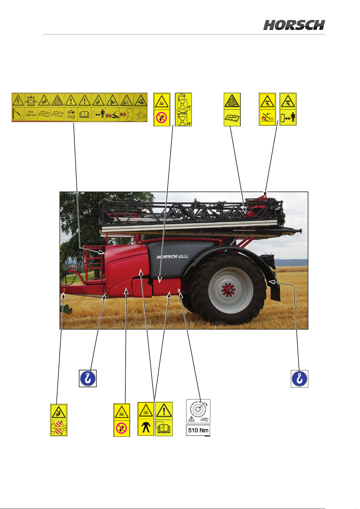
The danger notes are applied in the form of warning signs or safety stickers.
Their position and meaning is shown next!.
NOTE
Become familiar with the meaning of the
adjacent warning signs.
The opposite texts and the attachment
location on the machine provide information about the special danger spots on the
machine.
Keep all warning signs on the machine in
clean and legible condition! Replace illegible
warning signs!
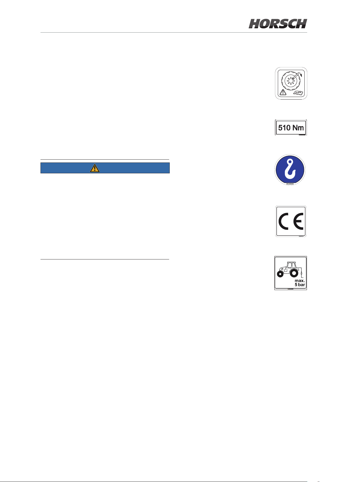
Check and retighten wheel nuts or
wheel bolts at regular intervals see maintenance overview!
00380359
00380359
Tightening torque for wheel studs /
wheel nuts - 510 Nm
00385489
Loading hook; attach lifting tackle
(chains, ropes, etc.) here when
performing loading work.
00380880
The CE-sign indicates that the machine complies with the basic health
and safety requirements.
00380067
The return pressure of the hydraulics from the crop protection sprayer
to the tractor must not exceed
5 bar.
04004899
1.18 Safety stickers
Safety stickers on the machine warn of hazards
at dangerous points and are an important part
of the safety equipment of the machine. Missing safety stickers increase the risk of severe or
even fatal physical injuries.
¾ Clean soiled safety stickers.
¾ Damaged or illegible safety stickers must be
replaced immediately.
¾ Provide spare parts with the specied safety
stickers.
29
Page 30
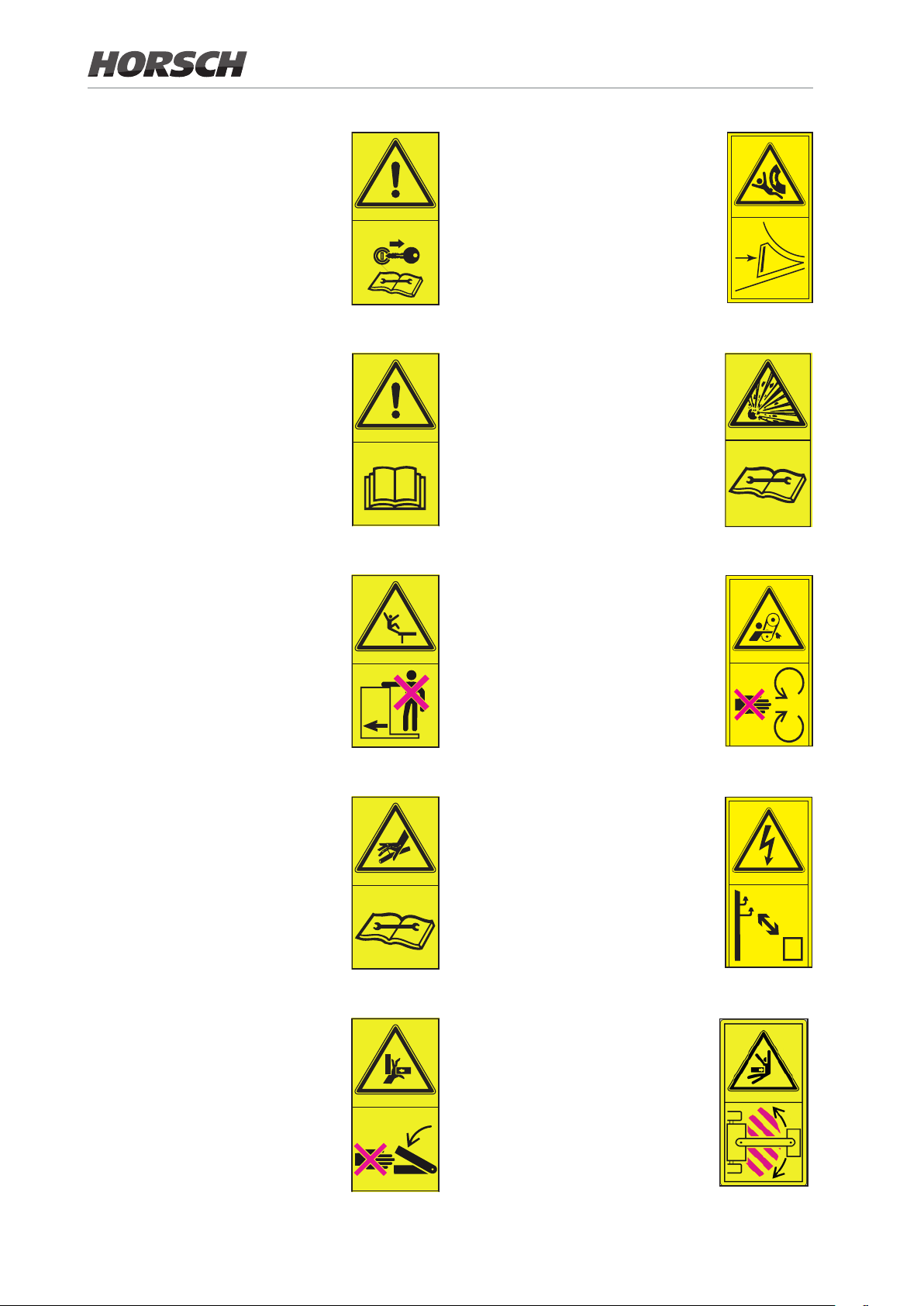
Switch the engine o and pull out
the key before starting maintenance
and repair work.
Endangerment caused by accidental movement of the machine!
Before commissioning the machine
you should read and follow the op
erating instructions!
No passengers are allowed to ride
on the machine!
04002983
-
04002983
04001455
04002983
The pressure accumulator is
charged with gas or oil pressure.
Dismantle and repair only in strict
compliance with the instructions in
the technical manual.
04001679
Do not open or remove protective
features while the engine is running!
04002983
Take care of emerging high pres-
sure uid! Follow the notes in the
operating instructions!
Never reach into areas where there
is a risk of crushing as long as parts
could still be moving!
04002983
04001683
Keep a sucient distance to electric
high voltage power lines!
04002983
Staying in the operating range of
the drawbar between tractor and
towed machine is prohibited!
04002622
30
Page 31
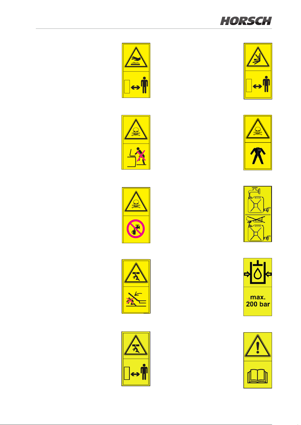
Danger of burning on hot surfaces.
Keep a safe distance to hot sur
faces!
Keep a safe distance to the slewing
-
area of the machine.
Danger of poisoning - never climb
into the tank!
Endangerment by inhaling hazard
-
ous substances!
Danger of poisoning - no drinking
water!
04001453
04001456
04002623
04001454
Avoid any contact with hazardous
substances!
Wear your protective outt
04003745
Fill the hand washing tank only with
clear water!
04002628
Do not stand in the slewing range
of the machine!
Do not stand inside the range of a
lifted but unsecured load.
04002625
04002626
The maximum operating pressure
in the hydraulic system is 200 bar.
Before commissioning the machine
you should read and follow the op
erating instructions!
04002983
-
i
04003747
31
Page 32
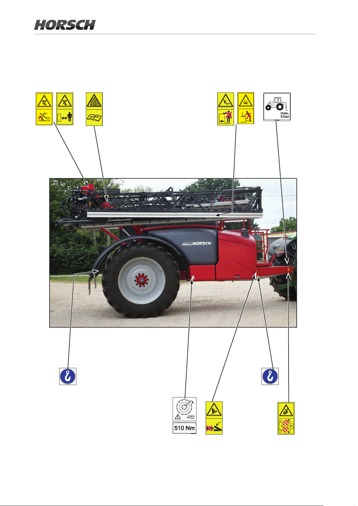
1.19 Position of safety
32
stickers
Page 33
i
33
Page 34
2. Product description
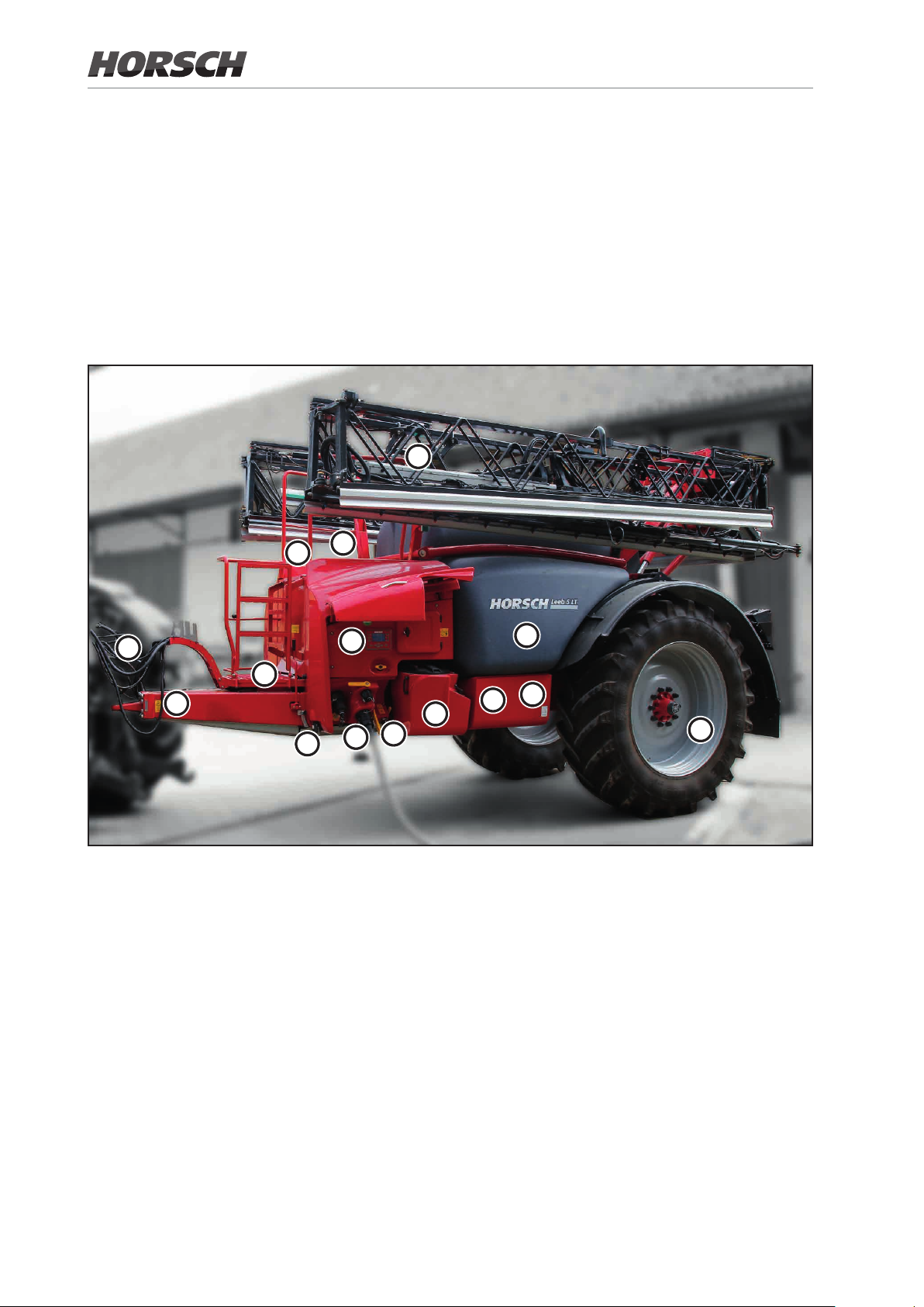
This chapter provides a comprehensive overview of the design of the machine and informs about
the individual assembly groups and actuating components. You should preferably read this chapter
directly on the machine. This is how you make yourself familiar with the machine.
2.1 Overview
b
h
e
l
m
n
c
f
o
g
a Spraying mixture tank
b Filling dome spraying mixture tank
c External control terminal with lling level
indicator
d Slewable illuviation valve
e Clear water tank
f Connection for clear water tank,
g Connection for spraying mixture container
a
P
d
i
h platform
i Hand washing tank
k Wheels and tyres
l hoses
m Access ladder
n drawbar
o Support
P Stowage compartment
k
34 35
Page 35
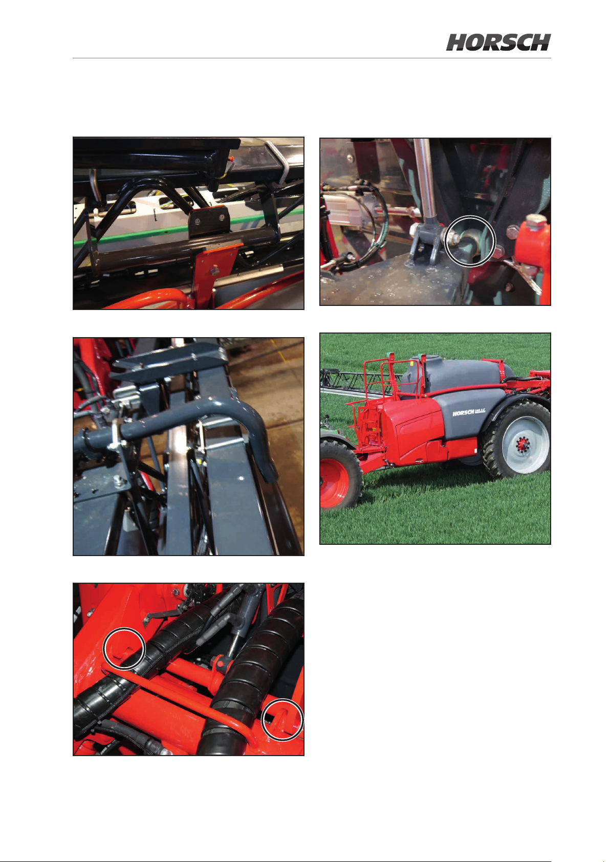
2.2 Safety and protective features
Folding boom rest for inside wings
Folding lock
Slope compensation
Railing for working platform
Parallelogram lock
Page 36
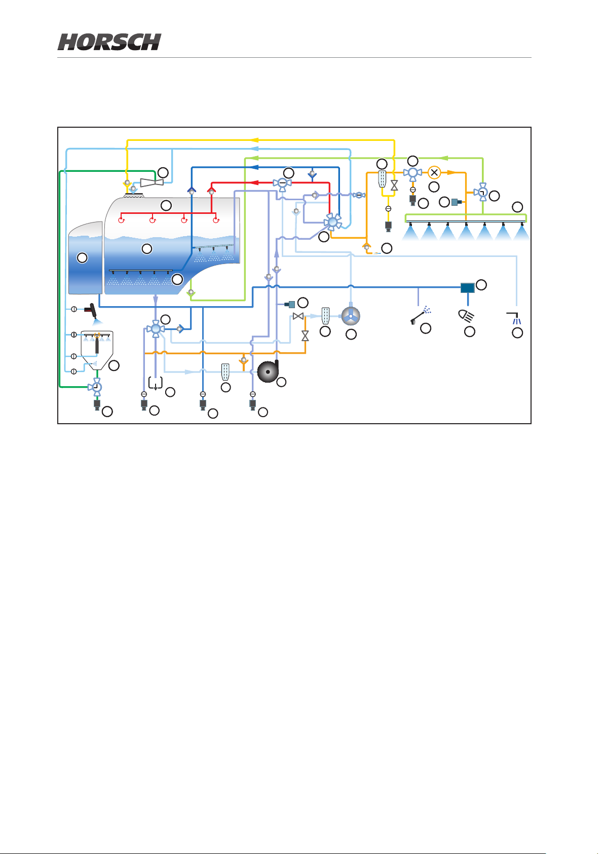
2.3 Fluid circuit LT CCS - components
21
22
2
24
25
1
23
3
5
4
8
6
30
14
12
10
9
7
15
11
16
18
12
17
13
26
19
20
29
27
28
1. Solution tank
2. Fresh water tank
3. Mechanical 5-way valve on suction side
4. Solution tank lling via suction
5. Residue drain
6. Fresh water lling
7. Direct lling
8. Suction lter with drain valve
9. Centrifugal pump
10. Fresh water lter
11. Piston diaphragm pump
12. Pressure sensor
13. Air function (optional)
14. Mechanical 6-way valve on pressure side
15. Pressure lter
16. 3-way valve pressure output
17. Pressure output
18. Flow meter
19. 3-way valve circulation
20. Folding boom
21. Injector
22. Internal cleaning
23. Agitator
24. Illuviation valve
25. Eco Fill
26. High pressure cleaner (optional)
27. Night Light cleaning
28. Outside cleaning (optional)
29. Electrical pump
30. Switch-over ball valve internal/outside
cleaning
36 37
Page 37
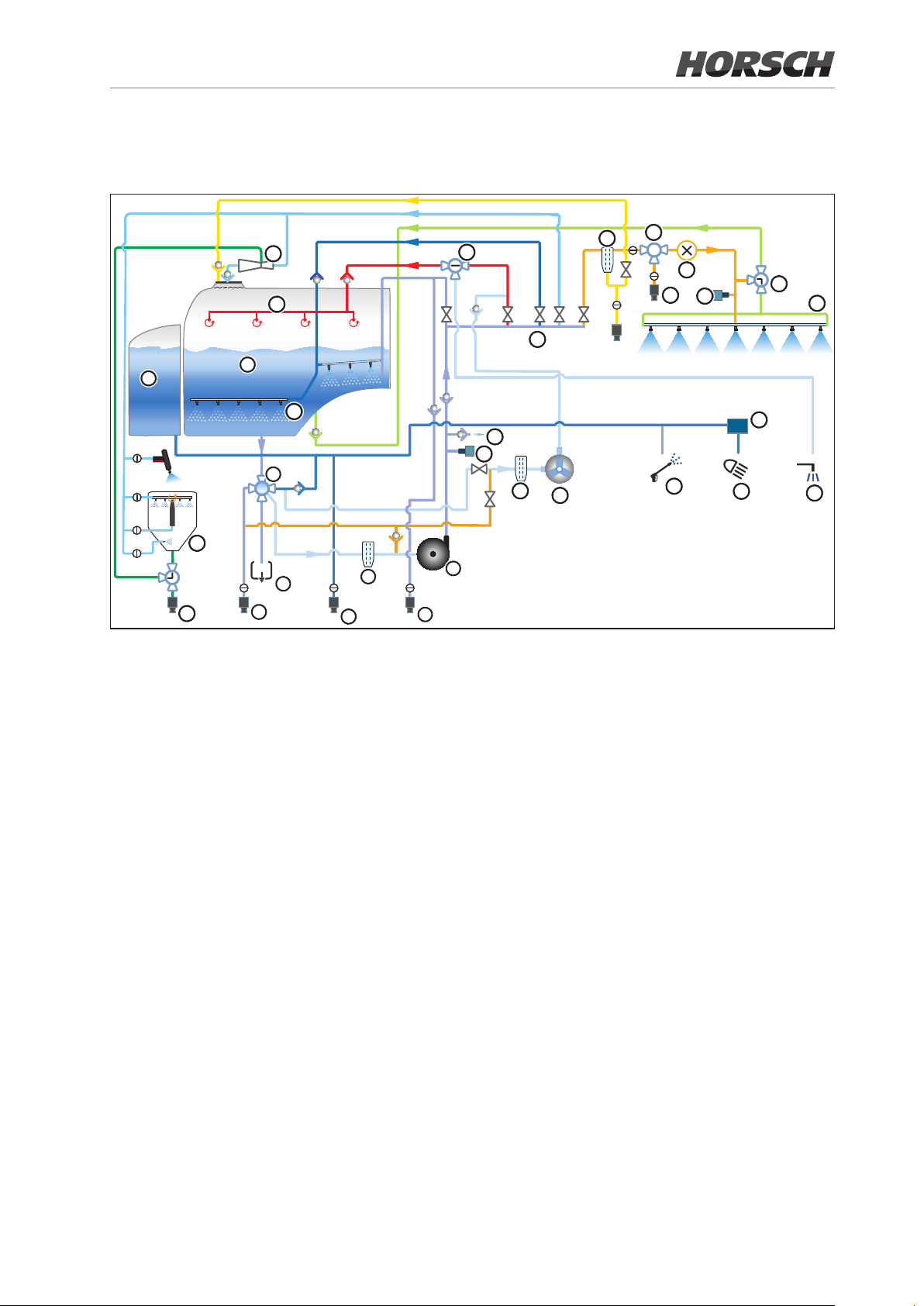
2.4 Fluid circuit LT CCS Pro - components
21
22
2
24
25
1
23
3
5
4
8
6
30
14
13
12
10
9
7
15
11
16
18
17
12
26
19
20
29
27
28
1. Solution tank
2. Fresh water tank
3. Electrical 5-way valve on suction side
4. Solution tank lling via suction
5. Residue drain
6. Fresh water lling
7. Direct lling
8. Suction lter with drain valve
9. Centrifugal pump
10. Fresh water lter
11. Piston diaphragm pump
12. Pressure sensor
13. Air function (optional)
14. Electrical control unit
15. Pressure lter
16. 3-way valve pressure output
17. Pressure output
18. Flow meter
19. 3-way valve circulation
20. Folding boom
21. Injector
22. Internal cleaning
23. Agitator
24. Illuviation valve
25. Eco Fill
26. High pressure cleaner (optional)
27. Night Light cleaning
28. Outside cleaning (optional)
29. Electrical pump
30. Switch-over ball valve internal/outside
cleaning
Page 38
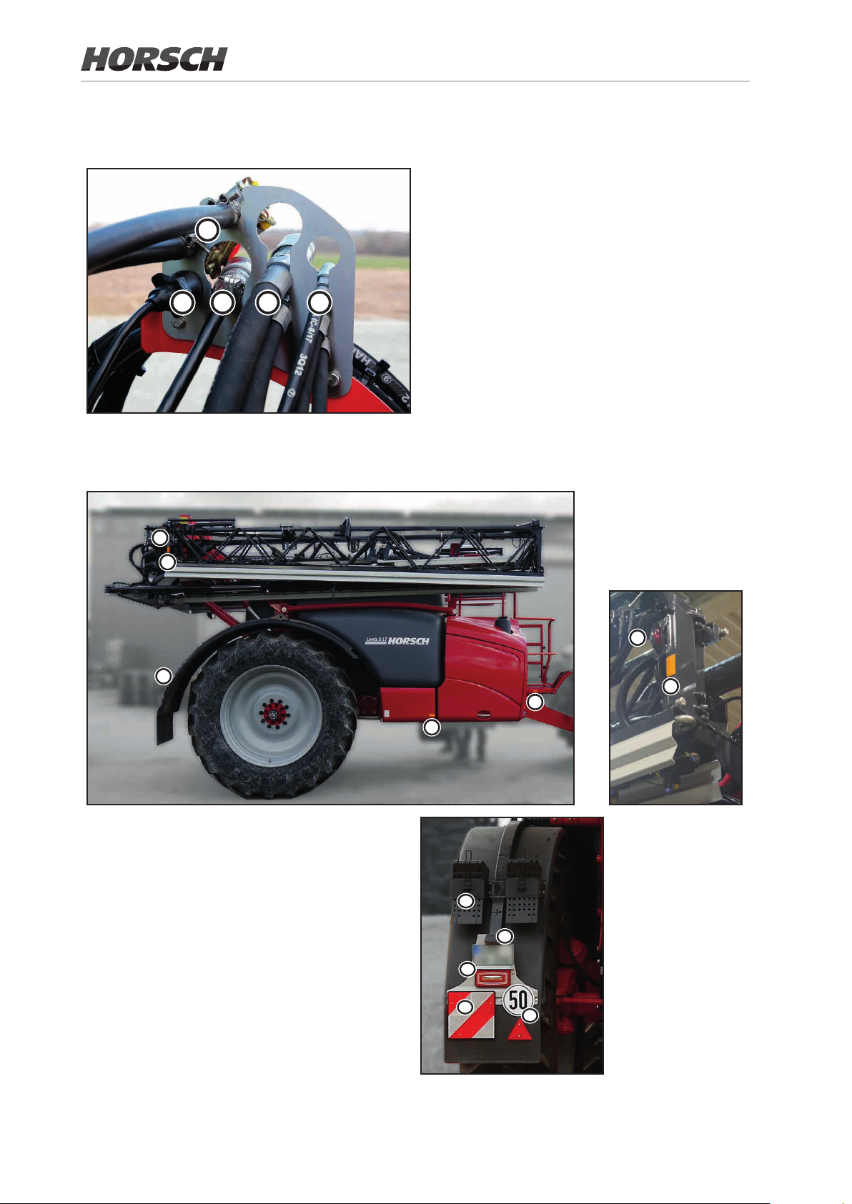
2.5 Supply lines between tractor and machine
Supply lines in parking position:
1. Pneumatic brake lines brake and reservoir
1
2. 7-pin plug for lighting
3. ISOBUS
4. Hydraulic connections pressure supply and
2
3
4
5
pressureless return
5. hydraulic connections LS-control line (Load
Sensing) and support
2.6 Trafc-compliant equipment
b
a
a
both sides:
(a) 4 spotlights, yellow
(b) red rear-light
(c) Warning board (square)
(d) red reector (triangular)
(e) Tail light / brake light
left:
(f) Number plate holder with lighting
(necessary, if the tractor number plate is
obscured)
(g) 2 wheel chocks
b
a
a
a
g
f
e
c
d
38 39
Page 39

2.7 Technical data
NOTE
Payload = permissible total weight - basic weight
DANGER
Exceeding the permissible payload is prohibited. Danger of accident caused by unstable driving!
Carefully determine the payload and thus the permissible lling of the machine. Not all lling media
allow a complete lling of the machine.
Machine type 4 LT 5 LT
Curb weight (kg) 4850 - 5850 4900 - 5900
Drawbar load empty (kg) 530 - 830 550 - 850
Axle load empty (kg) 4330 - 5020 4350 - 5050
max. total length in transport position (m) 7.40 7.40
Transportwidth in transport position (m) 2.55 2.55
Height (m)* 3.40 - 3.55 3.40 - 3.55
Track widths (m)* 1.80 / 2.00 / 2.25 1.80 / 2.00 / 2.25
Ground clearance (m)* 0.85 0.85
Hopper
Rated volume (litres) 4000 5000
Actual volume (litre) 4500 5500
Fresh water tank (litres) 500 500
Hand washing tank (litres) 15 15
Spray boom
Working widths 42 / 28 / (14) 7-piece
39 / 27 / (14) 7-piece
38 / 27 / (14) 7-piece
36 / 24 / (12) 7-piece
33 / 24 / (12) 7-piece
32 / 24 / 12 7-piece
30 / 24 / (12) 7-piece
30 / 21 / 12 7-piece
28 / 21 / 12 7-piece
27 / 21 / 12 7-piece
24 / 12 5-piece
21 / 12 5-piece
18 / 12 5-piece
Page 40
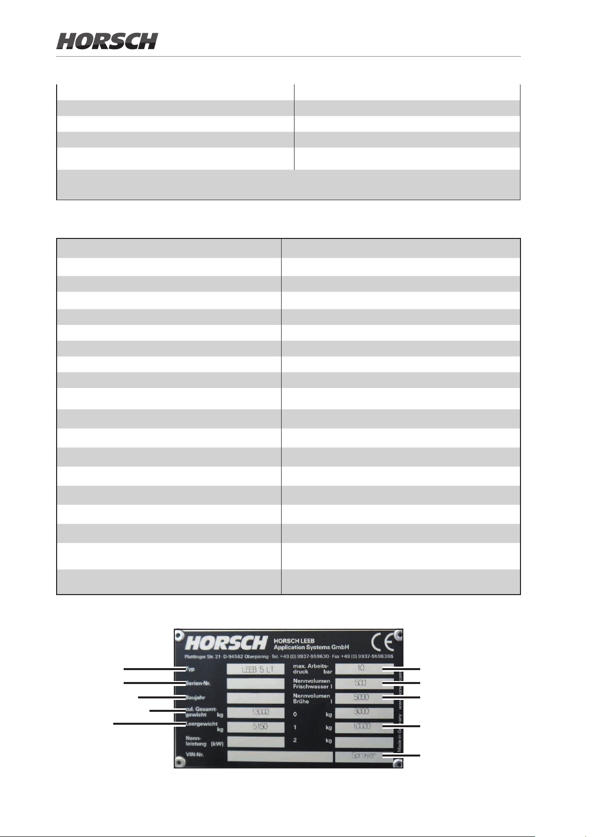
min./max. Sections (pieces) 6 / 18
Working height (m)* 0.3 - 2.5
Pump capacity Centrifugal pump (litres/min) 600
max. working pressure (bar) 8
Working speed (km/h) 4 - 20
All dimensions and weights depend on boom width, tyres and equipment.
* Data with tyres 520/85 R 46
Machine type 4 LT / 5 LT
Technical residual quantities incl. pump **
- level ground 15 litres
- Contour line
15 % travel direction to the left 17 litres
15 % travel direction to the right 18 litres
- Line of fall
15 % uphill 31 litres
15 % downhill 13 litres
Central control electric, pneumatic single nozzle control
Spraying pressure adjustment Electric
Spraying pressure - adjustment range 0.8 - 8 bar
Spraying pressure gauge digital
Pressure lter 50 (80) meshes
Agitator innitely adjustable
Placing quantity control speed dependent via job computer
Jet height 300 - 2500 mm
** depending on folding boom version, incl. use of air
function
Type plate
Machine type
Serial number
Year of construction
perm. total weight
Curb weight
max. working pressure
Rated volume, water
Rated volume, chemical
Axle load
Type of machine
40 41
Page 41
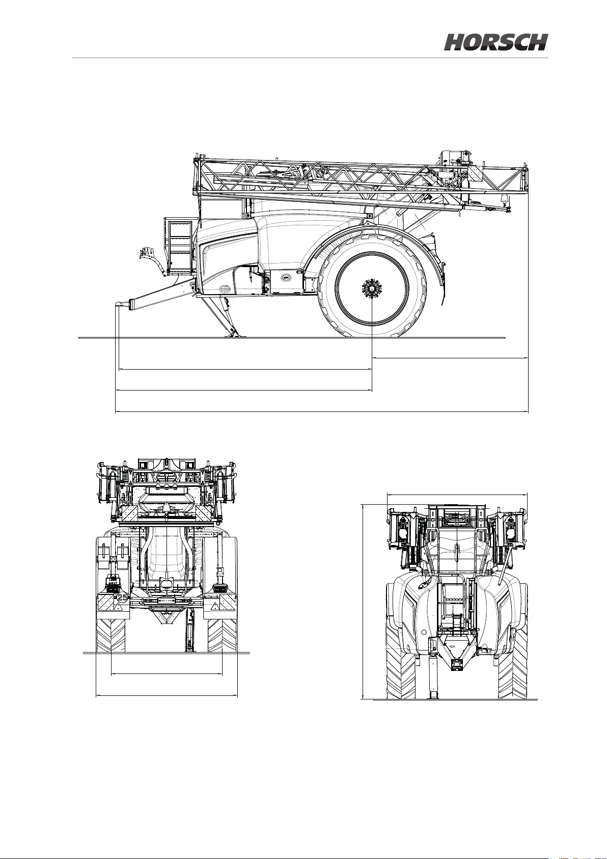
2.7.1 Dimensions
4750
Largeur de voie
E Voie 1,80 m 2,00 m 2,25 m
F Largeur horstout garde-boue 2350 2550 2550
Rampe
Rampe 24/12 X/21/12 x/24/12 X/27/14
G Largeur hors-tout rampe 2130 2524 2517 2517
Variantes de rampe
Flèche courte, Attelage à
boule inférieur
Rampe 24/12 x/21/12 x/24/12 x/27/14
A Empattement 4750 4750 4750 ---
B Porte à faux Avt 4812 4812 4812 ---
C Porte à faux AR 2321 2246 2928 ---
D Longueur hors tout 7133 7058 7740 ---
Variantes de rampe
Flèche longue, Attelage à
rueir´éfni eluob
Rampe 24/12 x/21/12 x/24/12 x/27/14
A Empattement --- --- --- 5150
B Porte à faux Avt --- --- --- 5212
C Porte à faux AR --- --- --- 2610
D Longueur hors tout --- --- --- 7822
Centre de
gravité cuve
Variante Y
4 LT 1248
5 LT 1156
6 LT 1090
4750
7740
4812
2550
2000
Data in mm
2928
4750
4812
7740
Side view 5 LT
3502
2000
2550
Rear view 5 LT Front view 5 LT
NOTE:
• Deviations due to technical further development reserved.
• The dimensions may vary depending on the machine equipment and design of the folding boom.
• The weight of the machine depends on the equipment.
• The permissible transport heights and transport width for transport on public roads may dier from country to country.
Comply with the national registration regulations.
2517
Page 42

2.7.2 Permissible total weight and tyres
The permissible total weight of the machine depends on
¾ the permissible drawbar load
¾ the permissible axle load
¾ the permissible tyre load bearing capacity per wheel pair
The permissible total weight is the sum of
¾ the permissible support load and
¾ the smaller value from
- the permissible axle load
- the tyre load bearing capacity per wheel pair!
The values for determining the permissible total weight can be taken from the following tables.
Permissible drawbar load: 4000 kg
Permissible axle load of the xed axle load
Design rigid steered rigid steered
Track [mm] 1800 - 2250 1800 - 2250 2000 - 2250 2000 - 2250
Axle load [kg]
(25 km/h)
Axle load [kg]
(40 / 50 km/ h)
Flange measurement [mm] 2000 2000 2100 2100
10 000 10 000 10 000 10 000
10 000 10 000 10 000 10 000
With decreasing tyre pressure, the tyre load bearing capacity will also decrease.
In this case pay attention to the reduced payload of the machine:
Load bearing capacity per wheel pair
Tyres Load index 25 km/h 40 km/h 50 km/h
1 Alliance
300/95 R52
2 Alliance
320/90 R50
3 Alliance
320/90 R54
permissible
load bearing
capacities
(kg)
LI 135 D /
148 D / 156 D
LI 153 A8 3570 3.0 3300 3.0 3160 3.0
LI 154 A8 3670 3.0 3390 3.0 3260 3.0
2390 2.1 2210 2.1 2120 2.1
3350 3.0 3100 3.0 2970 3.0
4270 4.0 3940 4.0 3780 4.0
4740 4.8 4380 4.8 4200 4.8
3710 3.2 3430 3.2 3290 3.2
3840 3.4 3550 3.4 3400 3.4
3970 3.6 3670 3.6 3520 3.6
3820 3.2 3530 3.2 3380 3.2
3960 3.4 3660 3.4 3510 3.4
4090 3.6 3780 3.6 3620 3.6
with air
pressure
(bar)
permissible
load bearing
capacities
(kg)
with air
pressure
(bar)
permissible
load bearing
capacities
(kg)
with air
pressure
(bar)
42 43
Page 43
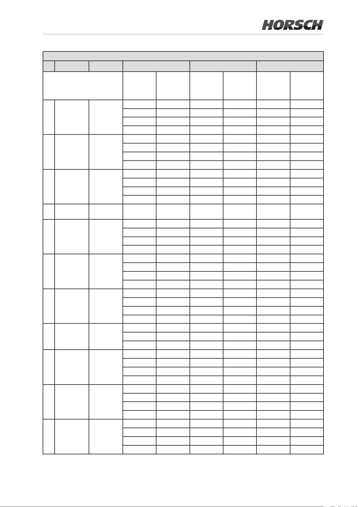
Load bearing capacity per wheel pair
Tyres Load index 25 km/h 40 km/h 50 km/h
4 Alliance
380/90 R46
VF
5 Alliance
380/105 R50
6 Alliance
420/80 R46
7 Alliance
480/80 R46
8 Alliance
480/80 R50
VF
9 Alliance
520/85 R38
IF
10 Alliance
520/85 R42
11 Alliance
520/85 R46
12 Alliance
520/85 R46
VF
13 Alliance
650/85 R38
14 BKT RT855
480/80 R42
permissible
load bearing
capacities
(kg)
LI 173 D 3150 1.2 3150 1.2 3150 1.2
4250 2.0 4250 2.0 4250 2.0
5450 3.2 5450 3.2 5450 3.2
6000 4 6000 4 6000 4
LI 171 A8 3100 1.2 2870 1.2 2750 1.2
4180 2.0 3870 2.0 3710 2.0
5510 3.2 5090 3.2 4880 3.2
6640 4.4 6130 4.4 5880 4.4
LI 151 D /
159 D
LI 158 A8 /
158 B
LI 171 D 3350 0.8 3350 0.8 3350 0.8
LI 167 D 2970 0.8 2970 0.8 2970 0.8
LI 154 D /
165 D / 170 D
LI 173 A8 5810 2.4 5370 2.4 5150 2.4
LI 170 D 3750 0.8 3750 0.8 3750 0.8
LI 170 D 5610 1.6 5180 1.6 4970 1.6
LI 151 A8 2035 0.6 1900 0.6 1900 0.6
2140 0.8 1980 0.8 1900 0.8
3670 2.0 3390 2.0 3260 2.0
4590 2.6 4240 2.6 4060 2.6
5180 3.2 4790 3.2 4590 3.2
- - 4250 2.4 4250 2.4
4250 1.2 4250 1.2 4250 1.2
5450 1.8 5450 1.8 5450 1.8
6150 2.4 6150 2.4 6150 2.4
4250 1.4 4250 1.4 4250 1.4
4875 1.8 4875 1.8 4875 1.8
5450 2.4 5450 2.4 5450 2.4
2960 0.8 2740 0.8 2630 0.8
5010 2.0 4630 2.0 4440 2.0
6100 2.8 5640 2.8 5410 2.8
7110 3.6 6570 3.6 6300 3.6
6350 2.8 5870 2.8 5630 2.8
6870 3.2 6440 3.2 6090 3.2
4875 1.2 4875 1.2 4875 1.2
5450 1.4 5450 1.4 5450 1.4
6000 1.6 6000 1.6 6000 1.6
6390 2.0 5900 2.0 5660 2.0
6750 2.2 6240 2.2 5990 2.2
7110 2.4 6570 2.4 6300 2.4
2700 1.0 2520 1.0 2520 1.0
3030 1.2 2830 1.2 2830 1.2
3695 1.6 3450 1.6 3450 1.6
with air
pressure
(bar)
permissible
load bearing
capacities
(kg)
with air
pressure
(bar)
permissible
load bearing
capacities
(kg)
with air
pressure
(bar)
Page 44
Load bearing capacity per wheel pair
Tyres Load index 25 km/h 40 km/h 50 km/h
15 Michelin
Mach X BIB
650/85 R38
16 Michelin
SprayBIB
420/95 R50
VF
permissible
load bearing
capacities
(kg)
LI 173 A8 3445 0.6 3000 0.6 3000 0.6
5245 1.2 4910 1.2 4910 1.2
6125 1.8 5710 1.8 5710 1.8
6955 2.4 6500 2.4 6500 2.4
5150 1.8 5150 1.8 5150 1.8
5800 2.4 5800 2.4 5800 2.4
6625 3.0 6625 3.0 6625 3.0
7300 3.6 7300 3.6 7300 3.6
with air
pressure
(bar)
permissible
load bearing
capacities
(kg)
with air
pressure
(bar)
permissible
load bearing
capacities
(kg)
WARNING
Never choose an air pressure lower than the once mentioned in the table above.
Danger of accident! The stability of the vehicle is no longer ensured.
with air
pressure
(bar)
44 45
Page 45

2.8 Nose development data
The work place related emission value (sound pressure level) is 74 dB(A), measured in operating
condition with the cabin closed at the ear of the tractor driver.
Measuring instrument: OPTAC SLM 5.
The sound pressure level mainly depends on the vehicle used.
2.9 Necessary tractor equipment
The tractor must meet the specied power requirements and should be tted with all necessary
electric, hydraulic and brake connections, to be able to work with the machine.
Tractor engine power
4 LT from 85 kW (115 HP)
5 LT from 90 kW (124 HP)
6 LT from 95 kW (130 HP)
Note: These values apply for level areas. Depending on use conditions (e.g. very steep /
hilly terrain) higher engine power may be required.
Electrics
Battery voltage: 12 V (Volt)
Socket for lighting: 7-pin
Hydraulics
Maximum operating pressure: 200 bar
Tractor pump power: Pump ACE FM 650-HYD M16:
min. 50 l/min at 190 bar for hydraulic pump drive
¾ The required pump capacity varies according to the function requirement!
Spraying pump
ACE 650
Piston diaphragm
pump
Max. required oil quantity 50 26 10 24 15 29
Application examples:
Field travel
Headland
50 50
50 10 24 84
Steering
Parallelogram lift
Hydraulic compres-
sor (optional)
High pressure
cleaner (optional)
Total output in litres
per minute
NOTE
All values represent the max. required amount of oil for the respective function!
Page 46

Hydraulic oil in the machine Hydraulic/gear oil OMV austromatik IGB
The hydraulic/gear oil in the machine is suitable for the combined
hydraulic/gear oil circuits in all common tractor brands.
Tractor control units: 1x dual-acting for hydraulic support
1x pressureless return
1x pressure supply
with hydraulic oil supply via Load-Sensing port:
1x Load-Sensing pilot line
with hydraulic oil supply via tractor control unit:
1 x pressure supply in continuous operation (min. 60 l/min)
Two circuit service brake system:
1 coupling head (red) for the supply management
1 coupling head (yellow) for the brake line
46 MF
Page 47
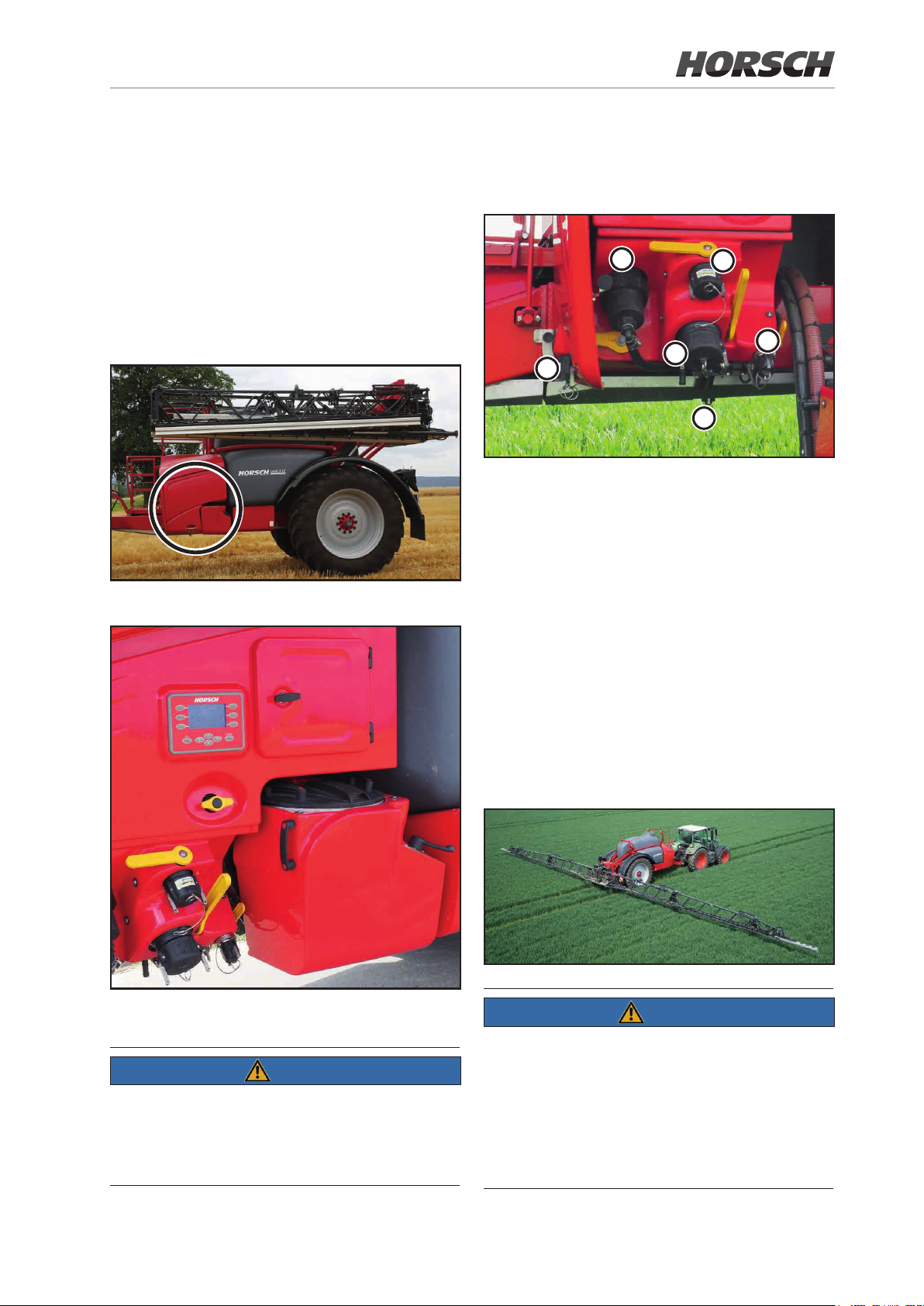
3. Design and
3.2 Connections
function
3.1 Control unit
The external control terminal, lling connections
and illuviation valve are arranged in travel direction on the left hand side.
Overview of connections
1
3
6
1 Pressure lter
2 Solution tank direct lling
3 Suction connection for solution tank lling
4 Filling port for fresh water tank
5 Spraying mixture tank residue drain
6 spraying mixture tank pressure output
2
5
4
External control terminal, lling connections and
illuviation valve
NOTE
For machines with the CCS Pro equipment there
is a storage box next to the external control
terminal. The personal protective outt can be
stored here.
3.3 Folding boom
The folding boom has 5 or 7 sections depending
on the version.
It can be operated in two dierent working widths
(full and reduced).
NOTE
Collision protection with fully extended
working width. With reduced working width
pay attention to any obstacles around the
outside of the machine!
¾ For possible folding boom versions see the
chapter Folding boom folding variants.
Page 48
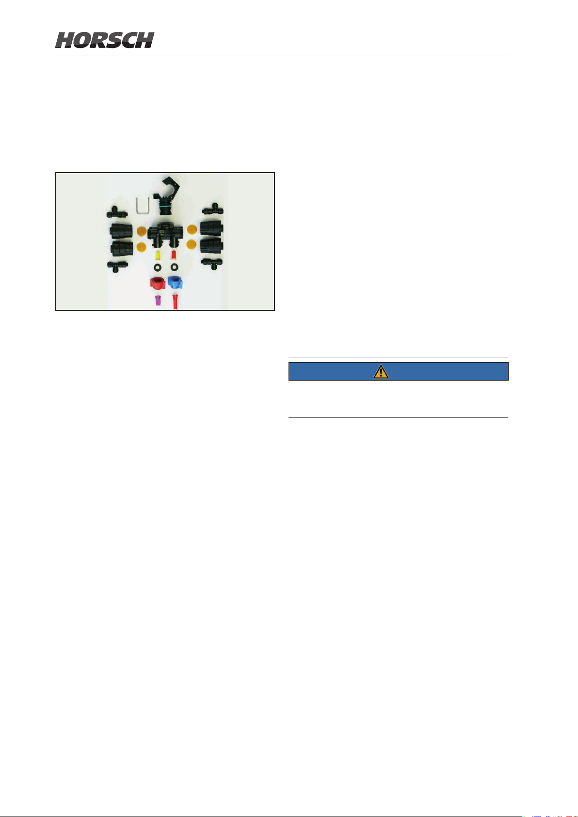
3.4 Nozzles
3.6 Spraying control
The boom can be equipped with single and
multiple nozzles.
The nozzles are mounted on the boom with a
spacing of 50 cm / 25 cm.
Example multiple nozzles body
¾ See appendix for further nozzle types
3.5 Spraying line
The complete control of spraying boom and
operation is accomplished via the terminal in
the tractor cabin.
See the "HORSCH terminal instructions" for
detailed operation.
Furthermore, the external control terminal is
used to control ushing, lling operation, working
lights and outside cleaning.
3.7 CCS - continuous inside cleaning
(Continuous cleaning system)
NOTE
Quick sprayer cleaning process without having
to get off the machine.
¾ The spraying line is made of Ø 25 mm stain-
less steel pipe.
¾ In the boom sections the pipe is continuous.
¾ The sections are coupled by hoses, resulting
in continuous lines over the entire width of
the boom.
The complete cleaning process is controlled
from the driver's cabin.
Function:
Principle of positive displacement instead of principle of dilution
An additional cleaning pump feed clear water
directly into the inside cleaning nozzles. The
spraying pump draws this water out of the
solution tank and uses it to force the chemical
residue through the nozzles out of the pipeline
system.
This means quick, thorough and water consumption optimized cleaning.
48 49
Page 49
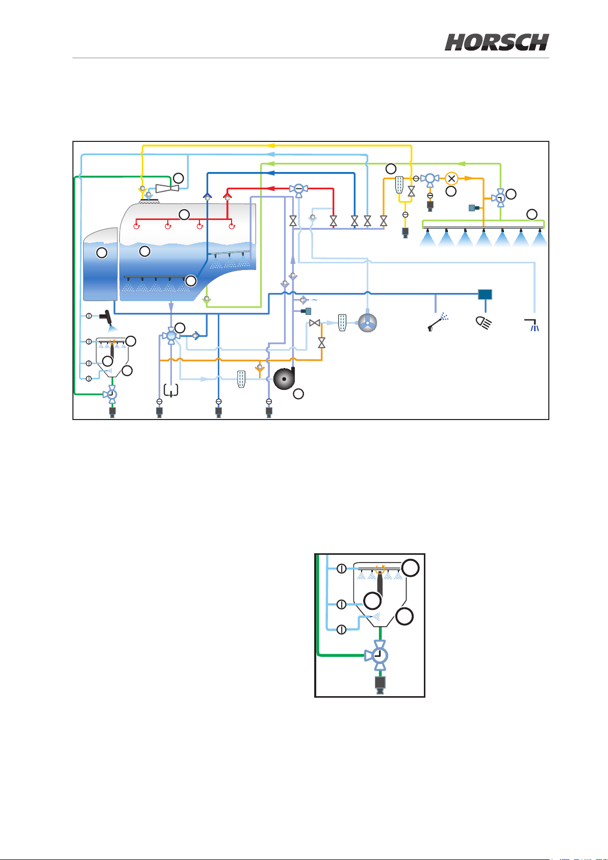
3.8 Fluid circuit - function
See also "Fluid circuit - components"
d
l
1) Filling
h
n
c
m
b
k
i
a
e
f
o
g
2) Suction
In lling mode, the externally sucked in uid is
drawn in through the spraying pump (a)
either
• directly into the solution tank (c)
or
• to the agitator of the solution tank (m)
or
• to the injector (h) induction hopper (i).
This draws preparations out of the induction
hopper into the solution tank.
The uid supplies the rinsing nozzles (k), the
shock nozzle (l) and the canister ushing of
the induction hopper. Function of the induction hopper only possible from 100 litre tank
content (c)!
The spraying pump (a) draws uid through the
suction tting (b) (electric ball valve) from the
solution tank (c) (spraying operation) or out of the
fresh water tank (d) (to clean the spraying system).
k
l
i
Page 50
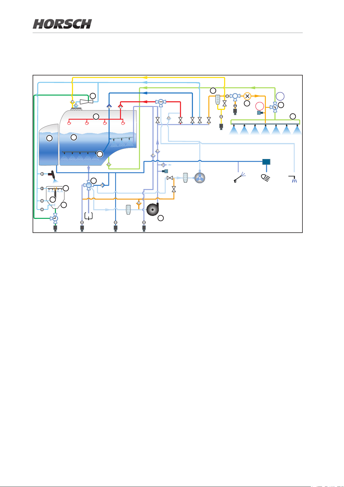
Function - continued
See also "Fluid circuit - components"
h
n
d
l
c
m
b
k
i
3) Spraying operation
a
4) Circulation
e
2
f
1
o
g
In spraying operation the drawn in uid is directed through the pressure lter (e) and the
ow meter (f) into the nozzle line (g).
The circulation valve (o) is in position (1), so that
pressure builds up in the nozzle line and chemical is pressed into the nozzles from both sides.
With the nozzles switched o, the circulation
valve (o) is in position (2), so that the spraying
uid ows through the nozzle line back into the
tank. This prevents the formation of deposits.
Chemical is immediately available at the nozzles
when switching on.
Due to the permanent circulation of the biocatalyst through the complete nozzle pipe while the
sprayer is switched o, spraying uid is permanently applied to all nozzles.
Even when switching on individual sections or
the entire spraying line for the rst time, the
biocatalytic solution is directly and well mixed
available.
This circulation successfully prevents the formation of deposits and blockage.
50 51
Page 51
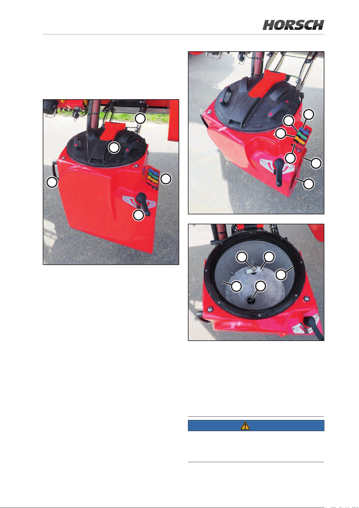
3.9 Induction hopper
The slewable illuviation valve is used to pour in,
dilute and draw in crop protection agents and
carbonyl diamide.
3
1
2
4
5
1 Hinged lid
2 Handle to swing the illuviation valve
3 Parallelogram arm to swing the induction hop-
per from transport to lling position
4 Switching tting for canister ushing / closed
circuit ushing line / shock nozzle and wash-
ing gun
5 Switch-over ball valve for sucking-o and
Ecoll connection
6 Washing gun
7 Ecoll lling port
8 Canister ushing
9 Rinsing nozzles
10 Shock nozzle
11 Washing gun
8
9
10
11
6
7
16
15
14
12
12 Filling level gauge
13 Eddy current valve
14 Rinsing nozzles to dilute and illuviate crop
protection agents
15 Pressure plate
16 Rotating canister ushing nozzle to ush
out canisters or other containers
13
NOTE
With the canister ushing (16) switched on, water
emerges from the rinsing nozzle when the pres-
sure plate (15) is pressed down.
Page 52

Washing gun
3.10 Spraying pump
A washing gun for cleaning the illuviation tank
after lling can be found on the induction hopper. Apart from this, deposited residues can be
ushed out of the canisters.
11
17
Washing gun
¾ To fixate the handle actuation press the
button (17) during operation.
¾ Operate the handle to loosen.
¾ After switching o (11) relieve the residual
pressure.
The crop protection sprayer is equipped with a
centrifugal pump for the spraying system. The
pump is hydraulically driven via a proportional
valve and adjusts to the required quantity.
Centrifugal pump
For the pumps used no pulsation dampening is
required, because centrifugal pumps generate
continuous ow and pressure.
The spraying pump is almost completely maintenance-free and is equipped with a dry running
protection.
The pump must never be operated without uid!
NOTE
Fill the pump with uid before initial commissioning and after each draining before switching on.
All uid residues must be drained o in order to
protect the pump against frost damage. Loosen
the screw for this purpose.
Technical data:
Type ACE - FMC-650F-HYD
Flow rate in l/min at 0 bar 600
Flow rate in l/min at 5 bar 500
Maximum pressure in bar 10
52 53
Page 53
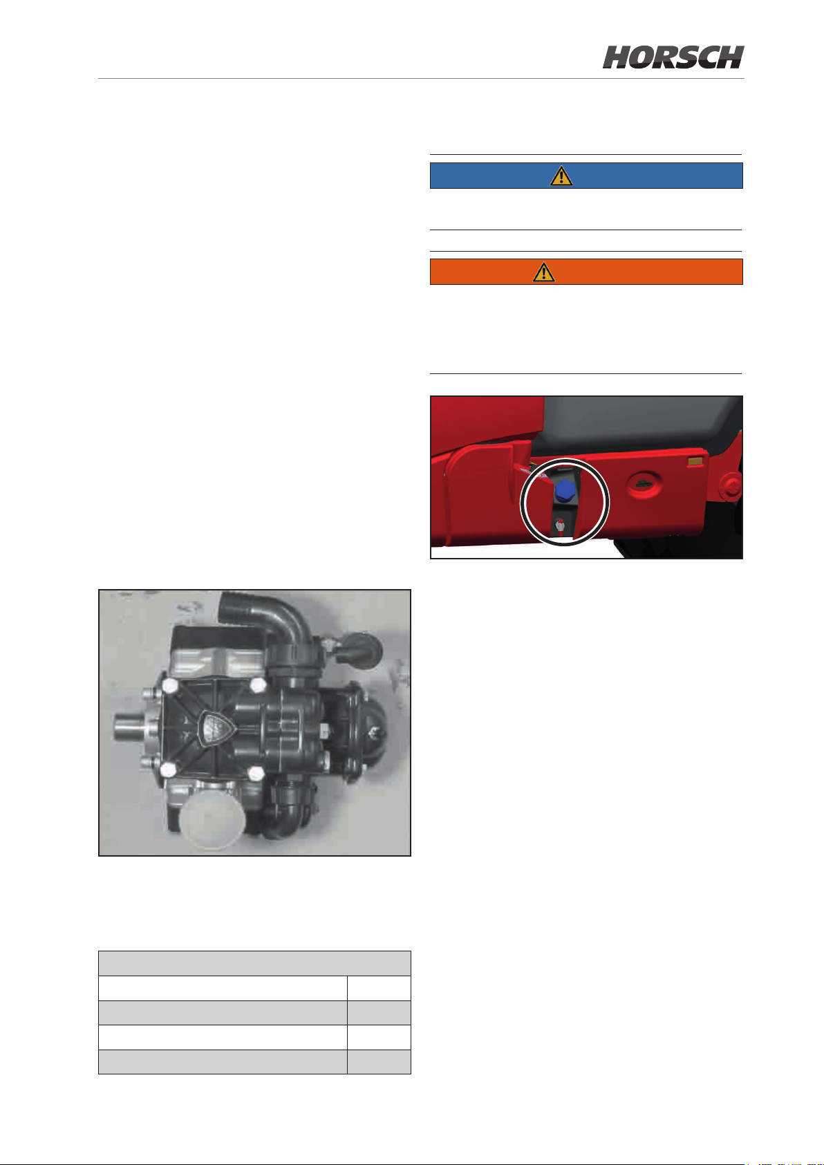
The pump has an oil lled cavity as dry running
protection and for cooling.
3.12 Hand washing tank
¾ Check the pressure in the pressure gauge of
the pump.
¾ If the pressure drops, check for leaks.
¾ Check the liquid sealant level.
¾ Switch the suction side to solution or fresh
water tank
¾ Open the main tap.
¾ The uid ows to the pump by itself.
3.11 Piston diaphragm pump
The piston diaphragm pump is located under
the fresh water tank.
Functions of the pump:
• Draws in fresh water during continuous inside
cleaning (CCS).
• Suction aid during lling process
NOTE
Fill only clean water into the hand washing tank!
WARNING
Danger or poisoning by contaminated water
in the hand washing tank!
Never use the water in the hand washing tank
as drinking water!
Hand washing tank
Piston diaphragm pump
¾ Check the tyre ller on the diaphragm pump
1x every year.
Technical data:
Type AR 135
Flow rate in l/min at 480 rpm 100
max. ow rate in l/min at 550 rpm 128
The hand washing tank with drain valve is located at the right hand side next to the illuviation
valve.
3.13 Agitator
The solution tank is equipped with a hydraulic
agitator. Special injector nozzles in the agitator
tube reinforce the stirring intensity. The switched
on agitator mixes the spraying mixture inside the
tank and thus ensures a homogeneous mixture.
The agitator can be adjusted innitely variable
on the external control unit or the terminal.
The agitator has 3 stages and can also be
switched o completely in order to minimize the
residual amount inside the solution tank.
At the greatest intensity, the quick lling valve is
also opened to create "turbulence" in the drum.
For machines with the CCS Pro equipment the
lling level wash container must be min. 150 litre
to activate the agitator.
Maximum pressure in bar 20
Page 54

3.14 Filter
NOTE
Use all specied lters of the lter equipment.
Clean the lters at regular intervals.
Trouble free operation of the crop protection
sprayer is only ensured with optimal ltration
of the spraying mixture. Appropriate ltering
considerably inuences the treatment success
of the crop protection measure.
Punched screen
The punched screen prevents that coarse contaminants can enter into pump and spraying
system.
Dome screen / lling screen
The dome screen / lling screen prevents contaminants from entering when lling the solution
tank through the dome or the induction hopper.
The screen has a standard mesh size of 1 mm.
Suction lter
Pay attention to the permissible lter combinations or mesh widths. The mesh widths of self-
cleaning pressure lters and nozzle lters must
always be smaller than the nozzle opening of
the nozzles used.
Please note that the use of pressure lter ele-
ments with 80 or 100 meshes/inch may with
some crop protection agents cause the separation of biocatalysts.
If in doubt, contact the crop protection product
manufacturer.
Pressure lter
The pressure lter prevents contaminants from
entering into the nozzle line. Dierent degrees
of neness are available to suit each application.
By standard the lter is tted with a 80 mesh/
inch element.
In case of applications with liquid fertiliser or
when using bigger nozzles it is recommended
to use more coarse elements in order to keep
the pressure drop in the lter as low as possible.
The suction lter clean the water / wash before
it enters into the centrifugal pump (mesh size
0.9 mm).
Overview of pressure lter elements
Meshes/
inch
32 white
50 blue from ‚03’ 0.35
80 grey ‚02’ 0.20
100 red up to ‚015’ 0.15
Filter cleaning, see chapter Cleaning,
maintenance and repair.
Colour nozzle
size
Mesh size
[mm]
The self-cleaning pressure lter prevents blocking of the nozzle lters in front of the spray
nozzles.
In circulation mode (sprayer main switch "o")
the inside surface of the pressure lter insert is
constantly ushed, and undissolved spraying
agent and dirt particles are caught in the dome
screen of the spraying mixture container when
the chemical is returned to the tank.
54 55
Page 55
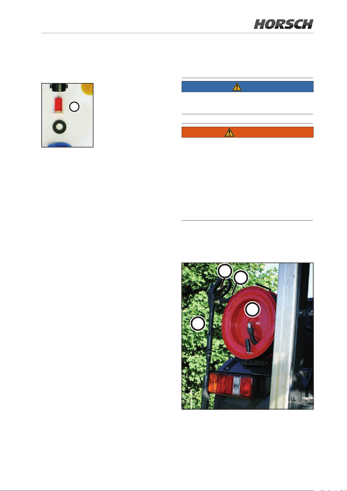
Nozzle lter (optional)
The nozzle lter (a) prevents clogging of the
spraying nozzles.
3.15 External cleaning system (optional)
NOTE
a
Overview of nozzle lters
24 Meshes/inch
from nozzle size: 06’ and bigger
Filter area: 5.00 mm²
Mesh size:: 0.50 mm
50 Meshes/inch
for nozzle size: 02’ to ‚05’
Filter area: 5.07 mm²
Mesh size: 0.35 mm
The external washing facility is supplied directly
by the spraying pump of the fresh water tank.
WARNING
Danger through accidental contact with spraying mixture!
Wear personal protection outt!
Before using the external cleaning system the
cleaning programs of the crop protection sprayer
must be cycled through since the residual
chemical still contained in the water system is
pumped o via outside cleaning before fresh
water arrives at the cleaning gun.
With the external cleaning system two optional
variants are available.
1. High pressure cleaner
100 Meshes/inch
for nozzle size: 015’ and smaller
Filter area: 5.07 mm²
Mesh size: 0.15 mm
4
2
1
3
1 Hose reel
2 20 m pressure hose
3 Washing gun
4 Grip with interlock
Page 56

Operating pressure: 150 bar
Water output: 15 l/min
3.16.1 Coupling hydraulic hoses
2. Washing facility with single spray gun
CAUTION
Risk of uids escaping under pressure.
The external cleaning system may be contaminated with spraying mixture deposits!
Secure the washing gun with the lock against
accidental spraying:
¾ before each spraying pause
¾ before the washing gun is stored again in its
holder after cleaning is nished.
NOTE
Wear appropriate protective clothes when cleaning. Follow the recommendations of the crop
protection agent manufacturers.
WARNING
Danger of crushing, cutting, being pulled in,
being caught and impact caused by faulty hydraulic functions in case of incorrectly connected
hydraulic hoses!
When connecting hydraulic hoses ensure correct assignment of the hydraulic connections.
¾ Check the compatibility of hydraulic oils before
you connect the machine to the tractor hydraulics. Do not mix mineral oils with bio-oils!
¾ Observe the maximum permissible hydraulic
oil pressure of 200 bar.
¾ Only connect clean hydraulic couplings.
¾ Insert the hydraulic plugs into the hydraulic
sockets, until they noticeably click into place.
¾ Check all coupling points of hydraulic hoses
for correct and leak tight t.
1. Actuate the control lever on the tractor
mounted control valve to oating position (or
neutral position).
3.16 Hydraulic connections
WARNING
Danger of infection caused by high pressure
hydraulic oil from the hydraulic system penetrating into the body!
Danger of severe injuries!
When coupling or decoupling hydraulic hoses
make sure that the hydraulic system has been
depressurized on both tractor and machine side.
If injured by hydraulic oil, consult a doctor immediately!
2. Clean the hydraulic plugs on the hydraulic
hoses before connecting the hydraulic hoses
to the tractor.
3. Couple the hydraulic hoses to the tractor control unit and ensure that they are interlocked.
56 57
Page 57
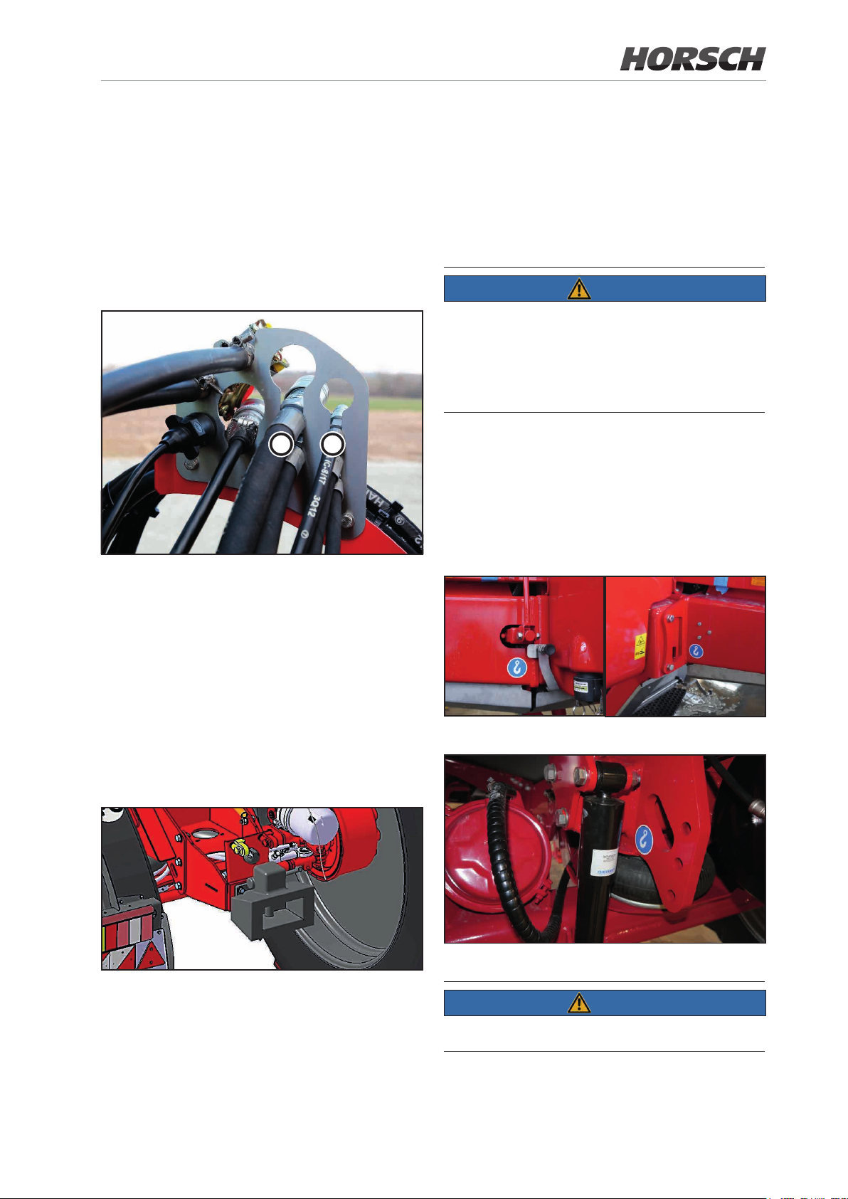
3.16.2 Uncoupling hydraulic hoses
The total weight of the trailer must be
¾ less or equal 12,000 kg and
¾ less or equal the actual total weight of the
trailed sprayer.
1. Turn the control lever on the tractor control
unit to oating position (neutral position).
2. Unlock the hydraulic plugs from the hydraulic
sockets and pull them o.
3. Place the hydraulic hoses in the hose bracket.
a
Hydraulic connections
(a) - Pressure supply
- pressureless return ow
b
The connections for lighting and brake are located above the drawbar hitch.
NOTE
Pay attention to the permissible towing capacity
of the tractor!
Strictly comply with the chapter Safety notes for
the operator!
3.18 Lifting points
The machine can be fastened at the following
points to secure it for transportation:
(b) - Support
- LS - control line (Load-Sensing)
3.17 Pulling tool (optional)
The drawbar hitch is intended for twin-axle trailers without drawbar load.
drawbar hitch
Both sides at the front of the machine
Both sides at the rear of the machine
NOTE
The chapter Safety notes must be followed!
Page 58

3.19 Transport, document
3.20 Pneumatic brake
and safety container
It is located at the right of the hand washing tank.
Machines with the CCS Pro variant feature an
additional storage bin to the right of the external
control terminal.
¾ Transport and safety container for the storage
of protective clothing and accessories.
¾ Document container for the storage and keep
of information concerning currently used crop
protection agents.
¾ Provides information about the composition of
the tank content and in the spraying boom and
serves as information for rescuing personnel
in case of accidents.
system
NOTE
Strict compliance with the specied maintenance intervals is mandatory for correct functioning of the twin-line brake system.
Brake pressure regulator with ALB for adjusting the brake force. The brake force is adjusted
in dependence on the loading condition of the
trailed sprayer.
WARNING
Danger of crushing, cutting, being pulled in, being caught and impact caused by accidentally
rolling machine after the service brake has been
released! Release the pneumatic brake and the
parking brake only after the machine has been
secured against rolling away.
Only on machines with CCS Pro variant
Hand brake
The parking brake of the towed sprayer must be
pulled each time when the unit is parked. To this
end, fold down the crank and apply the brake by
turning it. Now fold up the crank again.
58 59
Page 59
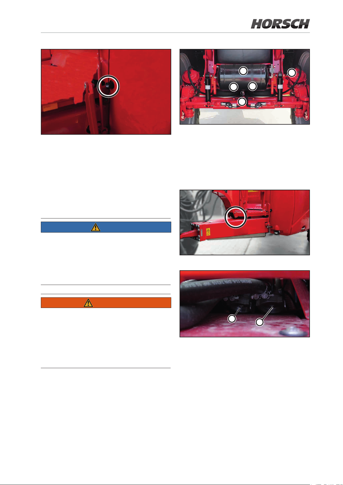
1
4
Actuating button to release the pneumatic brake
When uncoupling the machine from the tractor,
the pneumatic brake of the sprayer automatically engages in the brake position. Press in
the operating button down to the stop position
to release the pneumatic brake of the towed
sprayer. The pneumatic brake is activated again
by pulling it up to the stop position with the air
reservoir being lled.
NOTE
The operating button for releasing the pneumatic
brake shall be used only for temporary work,
e.g. for manoeuvring the machine or in case of
emergency. The pneumatic brake must be applied again at the end. The parking brake must
be pulled in addition.
2
2
3
(1) Air vessel
(2) Tension straps
(3) Drainage valve for condensation water
(4) Test port for pressure gauge
Twin-circuit pneumatic brake system
Position of line lters
WARNING
Danger of crushing, cutting, being caught, being
pulled in and impact caused by unintentional rolling away of the machine! When the air vessel is
empty, the pneumatic brake cannot be engaged
again via the operating button! The air reservoir
must be lled again rst by coupling the crop
protection sprayer to the tractor.
2
(1) Line lter in brake line (yellow)
(2) Line lter in supply line (red)
1
Page 60
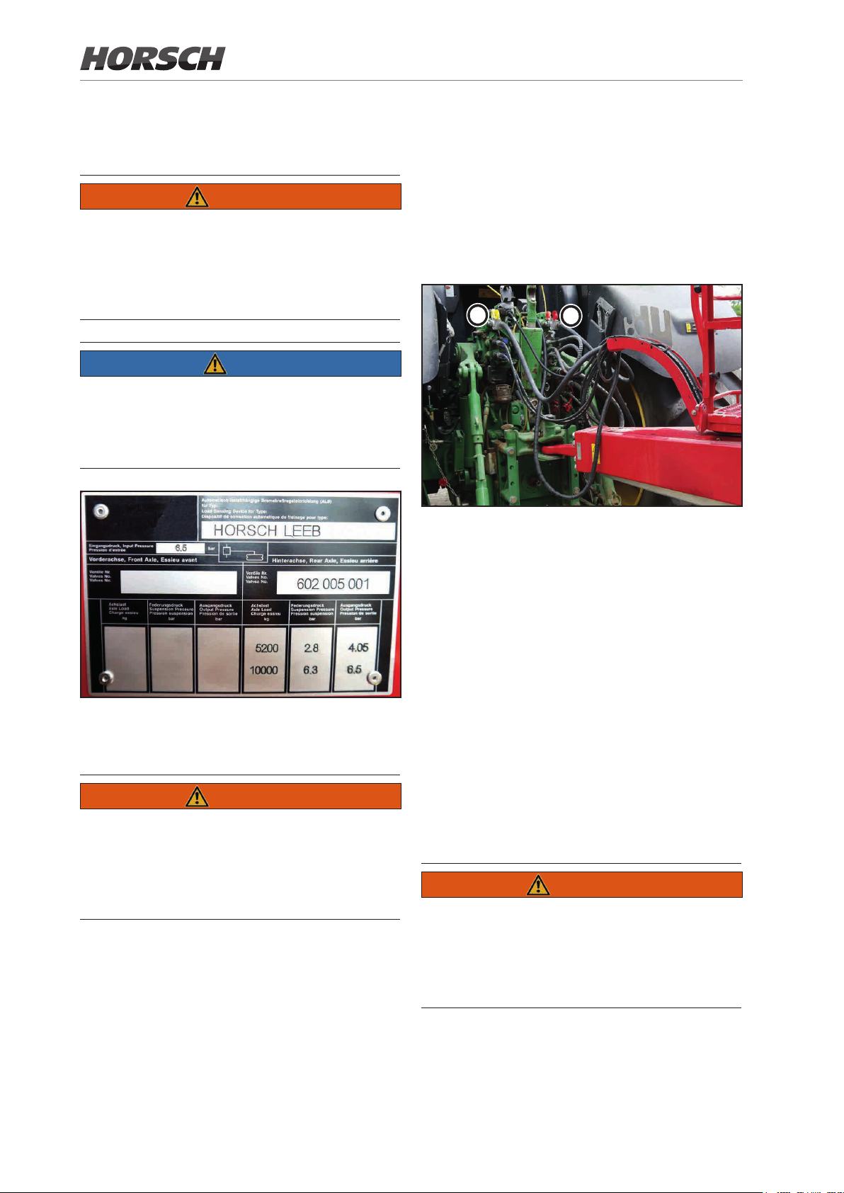
3.20.1 Automatic load dependent brake pressure regulator (ALB)
WARNING
Danger of crushing, cutting, being pulled in,
being caught and impact caused by incorrectly
functioning brake system!
Perform a function test of the brake system
before each travel!
NOTE
Do not change the adjustment measurement
on the automatic load dependent brake pressure regulator. The adjustment measurement
must match the value given on the ALB plate.
¾ Damaged seal rings must be replaced
without delay.
¾ Drain water from the air vessel every day
before the rst ride.
¾ Only start to move the hitched up machine
after the operating pressure required to
release the brake has been reached (pressure gauge on tractor).
2
1 Supply line (red)
2 Brake line (yellow)
1
Anti-lock braking system (ALB) sign
3.20.2 Connecting the brake system
WARNING
Danger of crushing, cutting, being pulled in,
being caught and impact caused by incorrectly
functioning brake system!
Perform a function test of the brake system
before each travel!
Before connecting the brake and supply line
make sure that
¾ the machine has been connected to the tractor.
¾ the seal rings on the brake coupling heads
are clean.
¾ the seal rings on the brake coupling heads
are not damaged.
1. Open the cover of the coupling head on the
tractor.
2. Fasten the coupling head of the brake line
(yellow) correctly in the yellow coupling on
the tractor.
3. Fasten the coupling head of the supply line
(red) correctly in the red coupling on the
tractor.
¾ When connecting the supply line (red) the
supply pressure from the tractor will press
the actuating button for the releasing valve
on the trailer brake valve automatically out.
4. Release the parking brake with the crank.
WARNING
Danger of crushing, cutting, being pulled in, being caught and impact caused by accidentally
rolling machine after the service brake has been
released! The machine must be secured against
rolling away.
60 61
Page 61
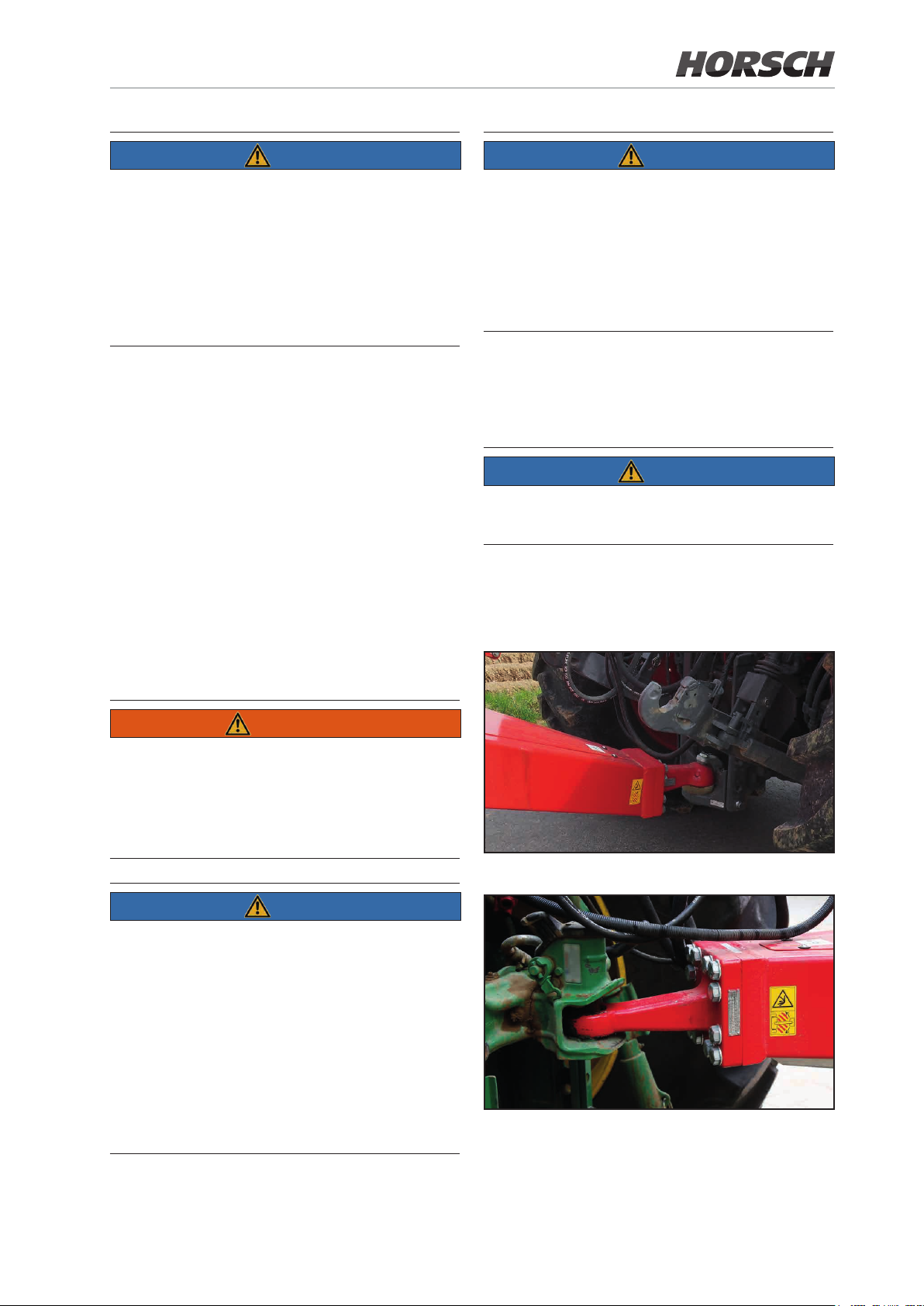
NOTE
NOTE
Pneumatic dual circuit brake system:
¾ Always connect the coupling head of the
brake line (yellow) rst and the coupling head
of the supply line (yellow) after.
¾ The service brake of the machine immediately
opens after the red coupling head has been
connected.
3.20.3 Disconnecting the brake system
1. Secure the machine against unintended rolling away. Use the parking brake and wheel
chocks for this purpose.
2. Pull the parking brake tight via the crank.
3. Release the coupling head of the supply line
(red) and uncouple from the tractor.
4. Release the coupling head of the brake line
(red) and uncouple from the tractor.
When the machine is unhitched or torn o,
the supply line to the trailer brake valve will be
vented.
The trailer brake valve will automatically switch
over and operate the service brake system in
dependence on the automatic load dependent
brake pressure regulator.
3.21 Drawbar
NOTE
Positively secure the coupling bolt after it has
been plugged in!
The drawbar is equipped with ball head K80 4 t
for lower link hitching or drawbar eye for connection in the coupling jaw.
5. Place the lines on the hose bracket.
WARNING
Danger of crushing, cutting, being pulled in, being caught and impact caused by accidentally
rolling machine after the service brake has been
released! The machine must be secured against
rolling away.
NOTE
Pneumatic dual circuit brake system:
¾ Always disconnect the coupling head of the
supply line (red) rst, and the coupling head
of the brake line (yellow) after.
¾ The service brake of the machine will only
change to braking position after the red coupling head has been disconnected.
¾ Strictly adhere to this sequence, as otherwise
the service brake will be released and the
unbraked machine may start to move.
Ball head coupling
Drawbar eye coupling
Page 62
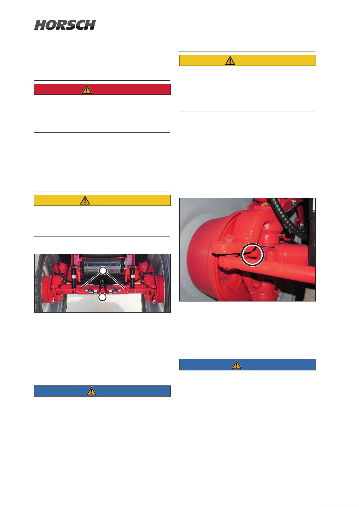
3.22 Automatic Ackerman steering
DANGER
Danger of accident caused by the machine tipping over!
For road travel and transportation center and
deactivate the Ackerman steering Trail-Control.
With Trail-Control switched on:
¾ Under 15 km/h: Trail-Control function active
¾ Above 15 km/h: Trail-Control function
switches o automatically!
CAUTION
Risk of accident from the machine topping over
at excessive speeds in curves e.g. at the headland. Corner only with appropriate speed.
CAUTION
Danger of ngers or hand being crushed by
moving, accessible machine parts!
Never reach into the danger spot as long as
the tractor engine is running with the hydraulic
system connected!
1. Switch on the steering axle.
2. Use the teach menu on the terminal to steer
the steering axle to the maximum position,
whereby any collision of wheels with other
machine parts must be avoided.
3. Screw out the stop screws until the axle
touches the end stop and secure them with
the locking nuts.
2
1
1 Trailing steering axle
2 Steering cylinder
3.22.1 Adjusting the mechanical steering end stop
NOTE
When using dierent tyres or track widths, the
mechanical steering stop needs to be adjusted.
In addition, the max. end stops must be taught
again.
¾ Teach procedure must be carried out by
HORSCH service sta.
Mechanical steering stop
Make this adjustment on both sides.
Depending on the equipment of the machine,
these stop screws are already assembled or
attached to the machine.
NOTE
Adjust the mechanical steering end stop so that
it is only activated when the electrical steering
end stop fails.
Refer to the HORSCH terminal instructions for
more details on adjusting the electronic steering end stop.
The undercarriage must be fully deflected
(air bellows relieved/pressureless). With the
wheels steered to the limit, check them for
freedom of movement.
62 63
Page 63
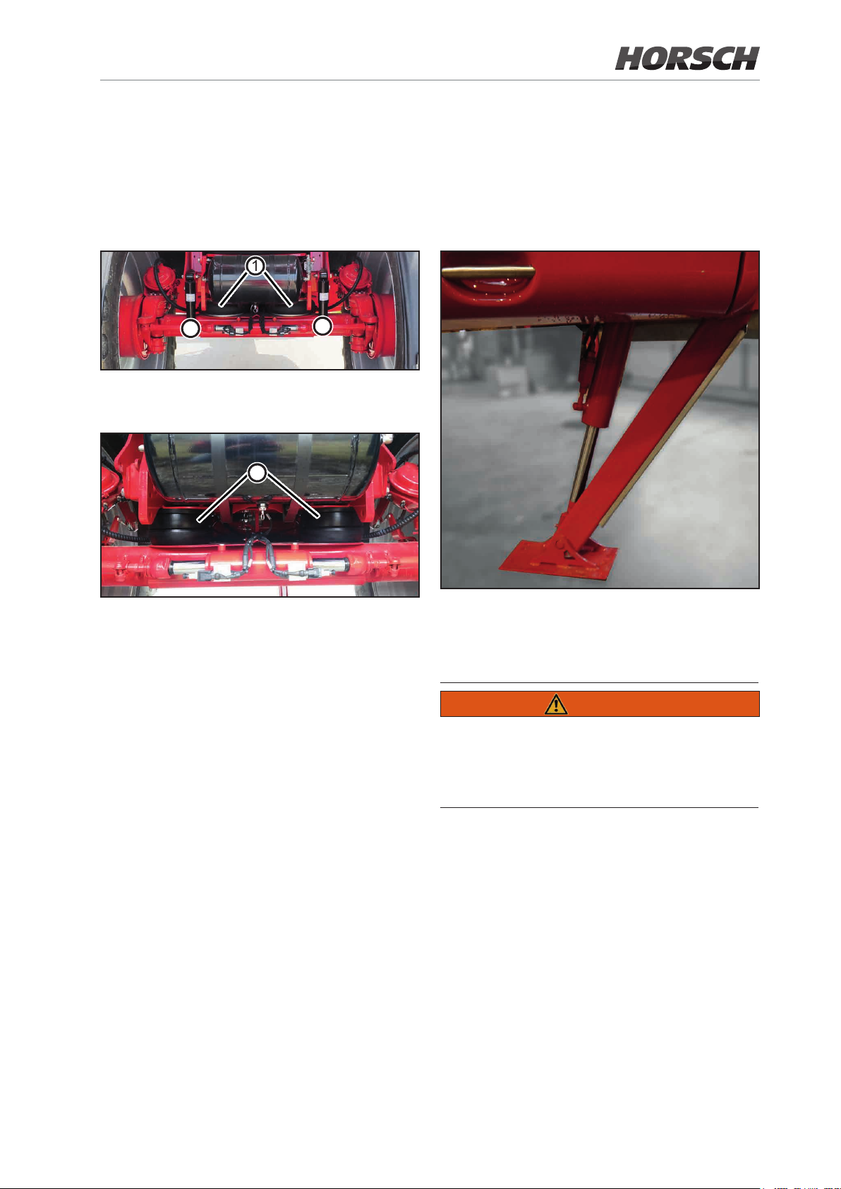
3.23 Suspension
3.24 Hydraulic support
The suspension includes an automatic level
control, independently of the load condition.
Suspension may work via air-spring bellows or
mechanical elastomer springs.
1
2
1 air-spring bellows
2 shock absorbers
3
2
The hydraulically operated support supports the
uncoupled trailed sprayer.
Operation takes place via a double-acting control valve on the tractor.
3 mechanical elastomer springs
hydraulic support
The hydraulic support is secured via a locking block.
This prevents accidental lowering.
WARNING
Danger of accident when driving with the support
in lowered position!
Before starting transport travels you must make
sure that the support has been fully retracted!
Page 64
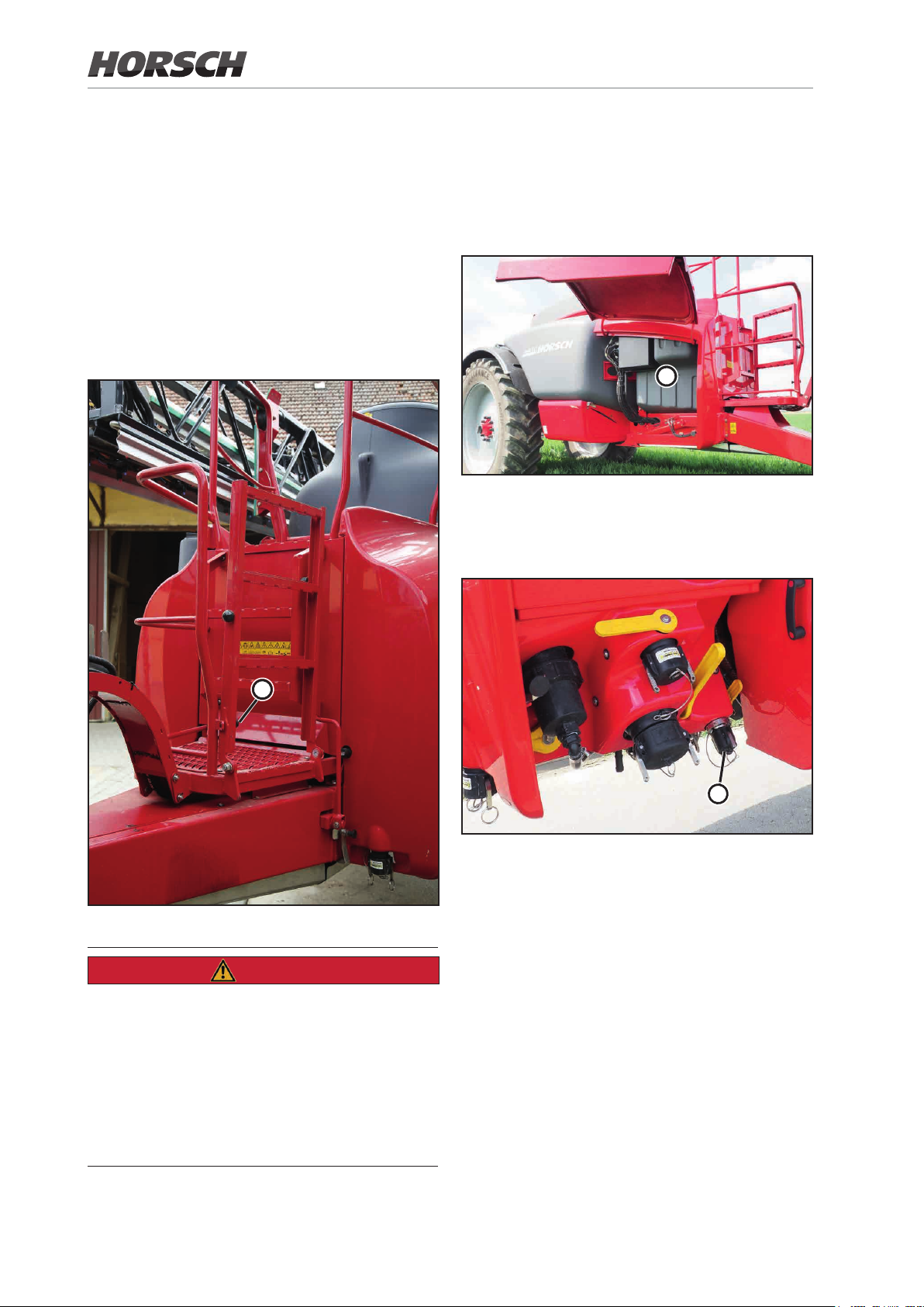
3.25 Working platform
3.26 Fresh water tank
with ladder
Working platform with foldable access ladder to
reach the lling dome.
¾ Hold on to the ladder.
¾ To open pull out the knob (1) and fold the
ladder down.
¾ Let the knob (1) click into place to fold up and
secure the ladder.
The fresh water tank (1) is located between the
platform and the solution tank. The tank capacity is 500 litres.
1
Fresh water tank
The lling port (2) is located to the left of the
illuviation valve.
1
Working platform
DANGER
¾ Danger of accident during transport by road!
Strictly make sure that the access ladder is
locked in transport position.
¾ Danger of falling o when riding on the ma-
chine! Riding on the crop protection sprayer
is generally prohibited
¾ Danger of injury by poisonous vapours! Never
climb into the spraying mixture container!
2
Filling port for fresh water tank
The overow of the fresh water tank is located
behind the lling port for fresh water which is
routed via a line to the underside.
64 65
Page 65
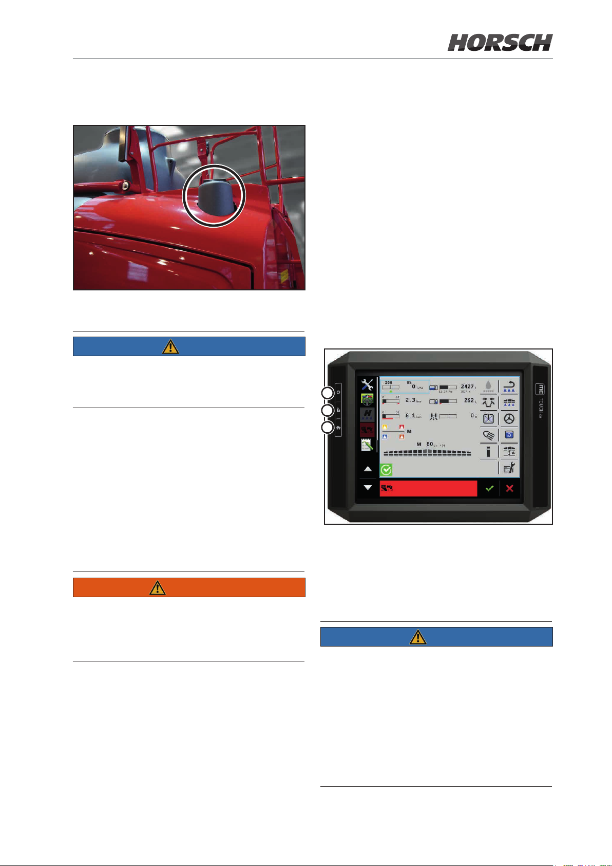
The tank lid with ventilation for the fresh water
tank is located at the top side.
Tank lid with ventilation of the fresh water tank
NOTE
Fill the fresh water tank only with clear water,
never with crop protection agent or spraying
mixture!
3.27 Main control terminal
Spraying operation is controlled via the terminal
in the tractor cabin.
The graphic user interface shows and controls
current settings and measuring values in spraying operation.
¾ Input and monitoring of data in spraying op-
eration.
The crop protection sprayer is equipped with
an ISOBUS-compatible terminal Touch 800 as
standard feature.
Other ISOBUS compatible terminals may alternatively also be used. However, this should be
discussed with the HORSCH- LEEB Service
before use.
1
2
3
4
Fresh water is used for:
¾ Dilution of the residual quantity in the spraying
mixture container.
¾ Cleaning (ushing) the entire crop protection
sprayer in the eld.
¾ Cleaning the suction tting as well as the
spraying lines with the tank lled.
¾ Cleaning with high pressure cleaner (optional).
WARNING
Danger of accident when performing repair work
on the fresh water tank! Open the maintenance
opening only for maintenance work and by
trained personnel.
Terminal Touch 800
1 Switching the terminal ON/OFF
2 Making screenshots
3 Saves the window arrangement
4 Touchdisplay
NOTE
¾ A detailed description can be found in the
operating instructions for the Touch 800
control terminal!
¾ Instructions for operating the sprayer software
can be found in the terminal instructions supplied by HORSCH!
¾ When using an alternative terminal the re-
spective operating instructions issued by the
manufacturer must be followed!
Page 66
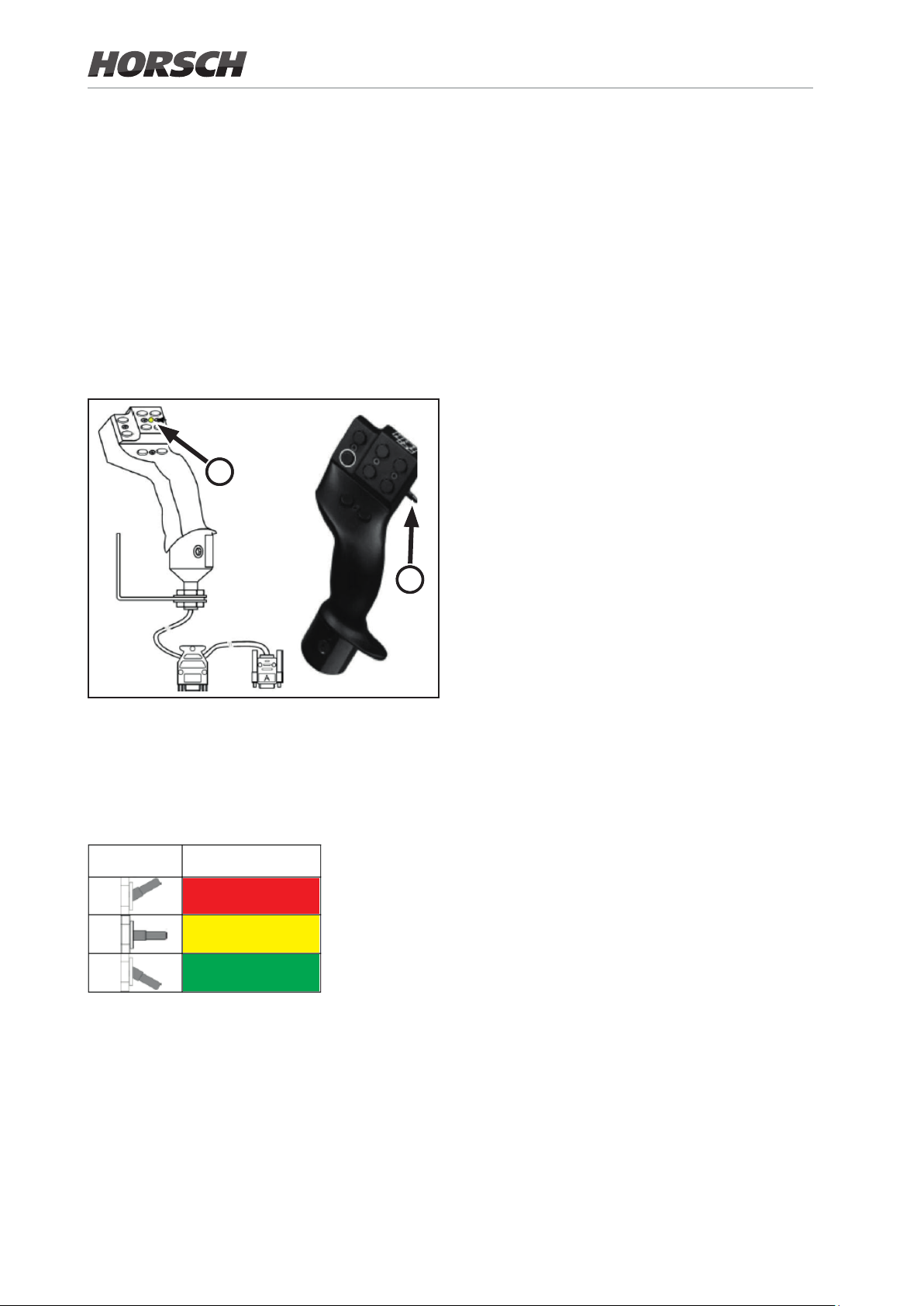
3.28 Multi-function handle
The multi-function handle can additionally be
connected to the terminal to ease operation.
It is denitely required for the operation of the
BoomControl function.
It contains the functions most frequently needed
during operation. These can thereby by selected
easily, quickly and without visual contact.
The number of screens is reduced by using the
multi-function handle and thus provides a better
overview.
1
2
The joystick has 8 buttons at the front side an a
switch (2) at the right side.
It allows changing between 3 levels. The currently set level is indicated on the front with a
colour LED (1).
Switch
position
Coloured status LED
Red
Yellow
Green
66 67
Page 67
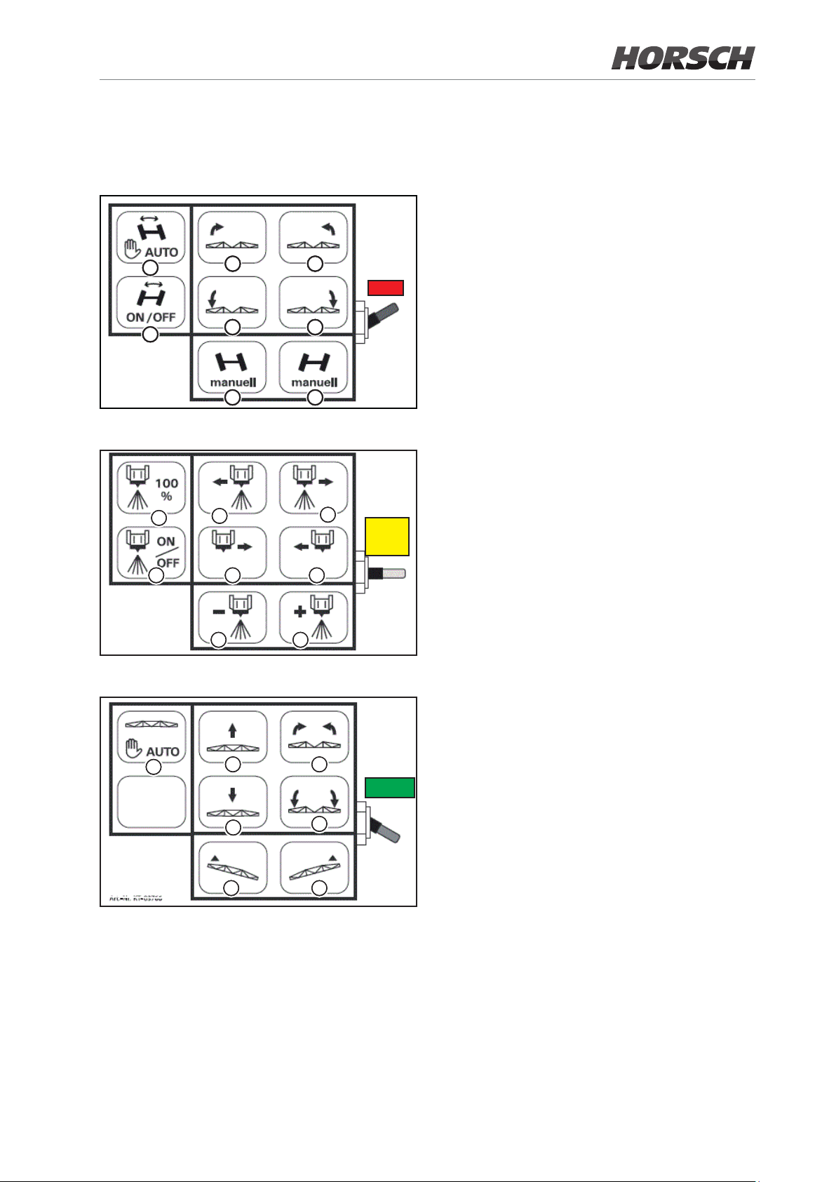
3.28.1 Assignment of multi-function handle
(a) Ackerman steering “Automatic mode”
(b) Ackerman steering “ON / OFF”
a
b
c
e
g
d
RED
f
h
(c)
Left folding boom wing up *
(d)
Right folding boom wing up *
(e)
Left folding boom wing down *
(f)
Right folding boom wing down*
(g) Steering “manual” travel direction “left”
(h) Steering “manual” travel direction “right”
(i) Spraying quantity “100%”, all sections on
(k) Spraying operation “ON / OFF”
i
k
m
o P
n
YELLOW
(m) Section “ACTIVATION” from “left”
(n) Section “ACTIVATION” from “right”
(o) Section “DEACTIVATION” from “left”
(p) Section “DEACTIVATION” from “right”
q
r
(q) Spraying quantity “REDUCTION” by 10 %
(r) Spraying quantity “INCREASE” by 10 %
(s) Activate automatic folding boom guidance
s
t u
V
x y
GREEN
w
**
(t) Lift folding boom or parallelogram *
(u) Angle both folding boom sides up *
(v) Lower the folding boom or parallelogram *
(w) Angle both folding boom sides down *
(x) Slope compensation “left” up
(y) Slope compensation "right" up
Button assignment on the multi-function handle
depending on the switch position or colour of
the status LED
* Optional
** Button assignment may vary
Page 68
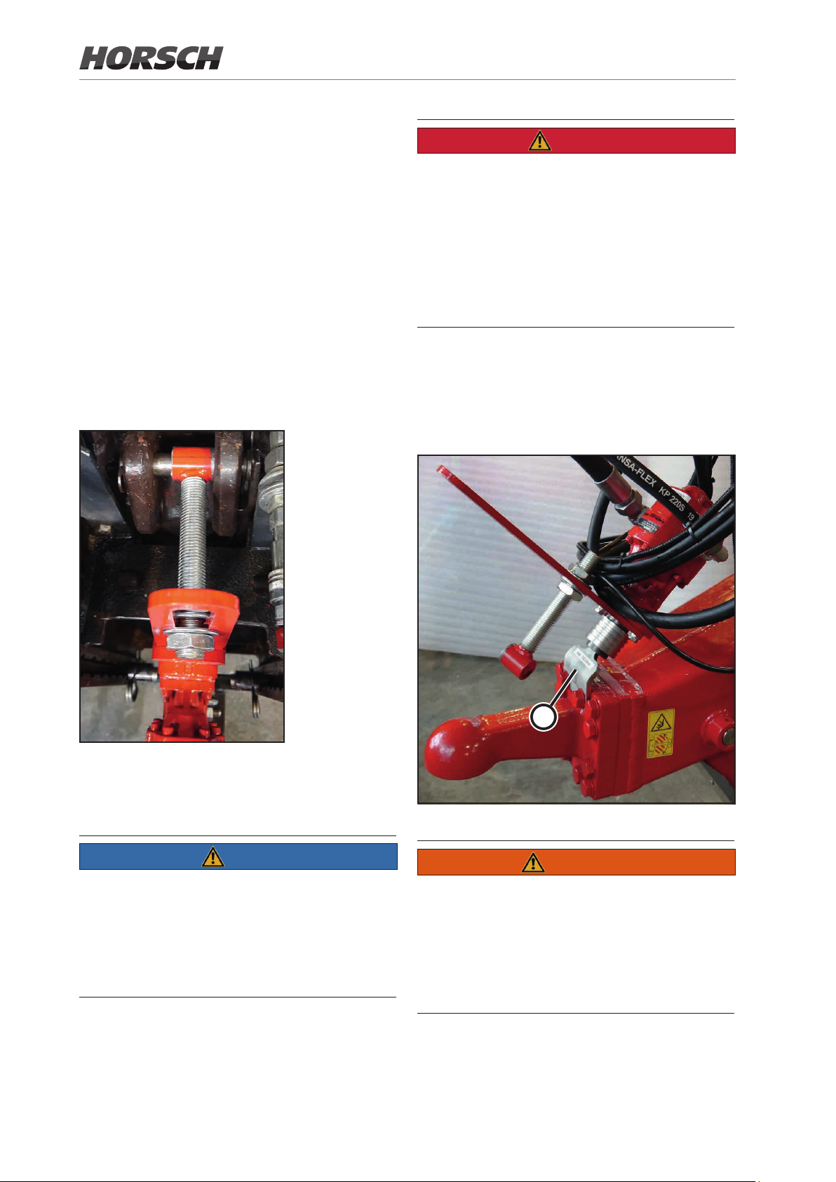
3.29 PTO-shaft pump (optional)
In case of insucient hydraulic power of the tractor the PTO-shaft pump can optionally be used.
The pump in this case supports the hydraulic
circuit for spraying.
Assembly
¾ Plug the pump on to the PTO-shaft.
¾ Fasten the anti-twist lock.
For this purpose x the adjusting rod in the
slot and in the bolt for the upper link without
applying any tension.
DANGER
Danger of injuring during assembly!
¾ Before performing assembly work shut down
the tractor and pull o the ignition key!
¾ Never switch on the PTO-shaft with the en-
gine shut down!
¾ Before switching on the PTO-shaft make sure
that there are no persons in the danger zone
of the machine.
Parking position
¾ After parking the machine plug the pump on
the holding plate (a).
PTO-shaft pump on tractor
The pump must not move during operation,
otherwise shaft and bearings may be damaged!
NOTE
¾ Before switching on the PTO-shaft make
sure that the chosen PTO-shaft speed of the
tractor complies with the permissible speed
of the device.
¾ Check all screw connections in regular in-
tervals.
a
PTO-shaft pump in parking position
WARNING
Danger of accident when driving the
PTO-shaft pump in parking position!
Parking position must only be used with the
machine shut down!
For road travel or in the eld the pump should
always be mounted to the tractor.
68 69
Page 69

3.30 NightLight (optional)
Extremely bundled light (LED spotlight) to illuminate the spraying cones.
When the spraying process is switched o at the
headland the lights are automatically cleaned by
a washing facility.
The LED spotlights are controlled via the terminal.
1
3
Pump NightLight cleaning (3)
The pmp is located at the undercarriage on
the left machine side below the solution tank
between the pressure tting and the travel axis
of the crop protection sprayer.
NOTE
NightLight with cleaning nozzle
The cleaning cycle is activated automatically
when switching o the nozzles (e.g. at the headland). At each cycle the pump (3) is activated for
approx. 4 seconds and delivers approx. 0.4 litres
of fresh water with 2.5 bar through the lter (2)
to the cleaning nozzle (1).
2
The cleaning cycle is also activated in the day-
time when the NightLight is switched o. This
avoids deposits on the spreading disc also during daytime.
Filter NightLight cleaning (2)
The lter is located below the fresh water tank.
Page 70

3.31 Hydraulic compressor
In the machine version with hydraulic brake a
hydraulic compressor is installed at the front
on the platform. It is operated via the tractor
hydraulics.
Compressed air supply takes place for
• Folding boom control
• nozzle control and blow-out function
• air bellows
The hydraulic compressor is automatically activated, if the system pressure drops below 6 bar.
4
3
5
2
1
Hydraulic compressor
6
¾ Replace the intake air lter every 500 operat-
ing hours, but at the latest after 6 months, under severe operating conditions even earlier.
Thereby clean the housing from inside.
Intake air lter
¾ Clean compressor block and fan protection
grille daily or when required. Carefully use
compressed air for this purpose.
Otherwise the compressor could overheat.
¾ Drain the water from the frame tube at least
once every week. For this purpose open the
drain valve slowly.
At ambient temperatures below 0 °C drain o
water after each work day / shift.
1 Hydraulic motor
2 Frame tubing
3 Cooling fan
4 Compressor block
5 Pressure gauge for air pressure
6 Vent valve
Maintenance
WARNING
Before starting maintenance, the tractor must
be shut down and the compressor depressurized! The pressure gauge should not indicate
any pressure.
Keep a safe distance to hot surfaces!
¾ Check the intake lter daily for contamination.
Clean as required.
¾ First oil change after 150 hours, then every
500 hours / 12 months.
Specication: SAE 10W-30 (0.9 l)
9
7 Filler neck with oil dipstick (min./max.)
8 Drain plug
9 Electronic pressure switch with ON/OFF switch
7
8
70 71
Page 71

Technical data
max. air ow rate 450
max. air pressure (bar) 8
Air volume in frame tube (l) 4.27
rated hydraulic volume (l/min) at 130 bar 14
Oil quantity (l) 0.9
Pressure switch electronic
Troubleshooting
Malfunction Possible cause Remedy
Compressor does not start,
even though the tractor is in
operation
Compressor does not start
or difficult to start, even
though the tractor is in
operation
Air pressure too low
Compressor does not
produce compressed air /
runs without load
Oil consumption too high
Compressor overheats
Fault on hydraulic valve of compressor or
on solenoid valve in hydraulic valve block
Compressor switched o by ON/OFF-
switch on pressure switch
Fault in hydraulic system • Check hydraulic pressure and ow rate,
Electronic pressure switch defective or
incorrectly adjusted
Suction lter blocked Check and replace if necessary
Output valve incorrectly adjusted or faulty Check and rectify fault (workshop work)
Intake air lter or connection blocked Check and replace the lter or clean the
Piston rings worn Check and rectify fault (workshop work)
Compressor lled with unsuitable oil Fill in suitable oil
Compressor block and fan guard soiled Check and clean
Oil level too low Fill in a sucient amount of oil
Check and repair, if necessary (workshop
work)
Switch on compressor
adjust as necessary (workshop work)
• Check hydraulic motor for leakage, repair
if necessary (workshop work)
Check and repair or replace, if necessary
(workshop work)
connection
Page 72
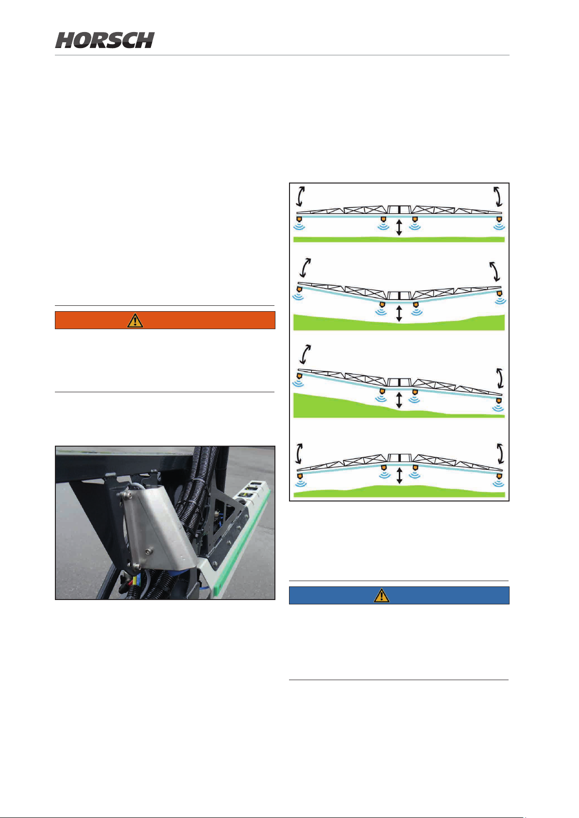
4. Design and
4.1.1 BoomControl
Function of the
Spraying Boom
4.1 Folding boom control
Proper condition of spraying boom and
suspension have a considerable inuence
on the distributing accuracy for the spraying mixture.
Complete overlapping is achieved by correctly adjusting the spraying height of the
boom to the crop.
WARNING
Danger cause by unexpected movements in
automatic mode. Never come close to the
ultrasonic sensor, while the BoomControl
is in automatic mode.
Further development of the automatic folding
boom guidance to maintain the exact, lowest
possible working height, even when driving with
high speed and in highly cropped terrain.
This creates the prerequisite for minimum drifting.
An automatic height and inclination control
adapts the boom to the crop.
Ultrasonic sensor on the boom
Active adaptation of the boom via middle section
height guidance; independent bending of both
boom arms (controlled by 4 sensors, distributed
over the entire boom);
NOTE
When the spray boom is switched o at the
headland, the spray boom is automatically
raised by a previously dened value.
When switched back on, the boom will return to
its adjusted height.
72 73
Page 73

4.1.2 BoomControl modes
Six dierent equipment versions are available. Depending on the mode, there are two designs each.
4.2 Folding and unfolding
WARNING
BoomControl ECO
Design with 2 or 4 sensors for height adjustment
and slope compensation.
BoomControl PRO
Design with 4 or 6 sensors for height adjustment,
slope compensation and angle adjustment.
BoomControl PRO+
Design with 6 or 10 sensors for height adjustment, slope compensation and angle adjustment
of inner wings and outer wings.
NOTE
In case of irregular population and/or empty
spaces in the population, the boom control must
be deactivated or manually overridden, to avoid
unintended lowering of the boom!
Danger of crushing, being pulled in, being
caught or impact for third parties may arise
if third parties remain in the operating range
of the boom when unfolding or folding the
boom and are caught by the moving parts
of the boom!
These endangerments can cause severe and
possible also fatal injuries.
Keep a sucient safety distance to moving parts
of the machine as long as the engine is running.
Make sure that persons keep a sucient safety
distance to moving parts of the machine.
Order persons to leave the slewing range of
the machine.
Immediately release the actuator for unfolding
or folding the boom, if a person enters into the
slewing range of the boom.
DANGER
Always keep a sufcient distance to overhead power lines when unfolding or folding
the boom! Contacting overheat power lines
can cause fatal injuries.
CAUTION
There are shearing and crushing points on
all hydraulically actuated folding components! Folding or unfolding the spray boom
while travelling is prohibited!
Only drive with the machine in locked transport position.
NOTE
The folding boom is controlled via the terminal.
In folded and unfolded condition of the boom, the
hydraulic cylinders for folding the boom maintain
the corresponding end position (transport and
working position).
Page 74

Folding process
For this purpose go to the page "Folding".
NOTE
¾ A detailed description can be found in the
operating instructions for the Touch 800
control terminal!
¾ Instructions for operating the sprayer software
can be found in the supplied terminal instructions from HORSCH!
74 75
Page 75

4.3 Folding variants - folding boom
Boom, 5-piece with reduced working width 12 m
12 m
18-24 m
Boom, 7-piece with reduced working width 12 m and 21 m
12 m
21 m
27-30 m
Boom, 7-piece with reduced working width 24 m
24 m
30-36 m
Boom, 7-piece with reduced working width 27/28 m
27/28 m
38-42 m
Page 76
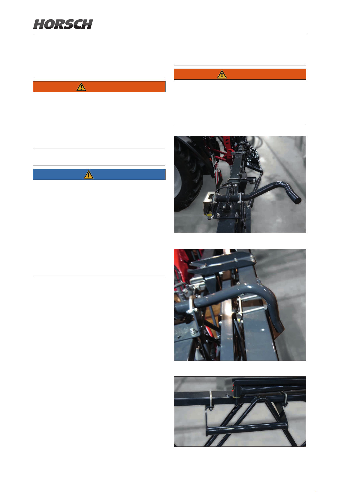
4.4 Adjusting the spraying height
4.5 Transport lock
WARNING
WARNING
Danger of crushing and impact for persons
when lifting or lowering for height adjustment of the spraying boom!
Expel persons from the danger zone of the machine, before lift or lower the spray boom with
the height adjustment.
NOTE
Adjust the spraying height (distance between nozzles and crop) as per currently
applicable guidelines.
Always adjust the spray boom parallel to
the ground, because the specied spraying
height can only be achieved in this condition.
Carry out all adjustment work on the spray
boom conscientiously.
Danger from crushing and impact for persons
may arise if the boom folded to transport
position accidentally unfolds during travels!
The folding boom package must be locked and
checked during each travel!
Folding boom lock open
Folding boom lock closed
Bow for folding boom rest
76 77
Page 77
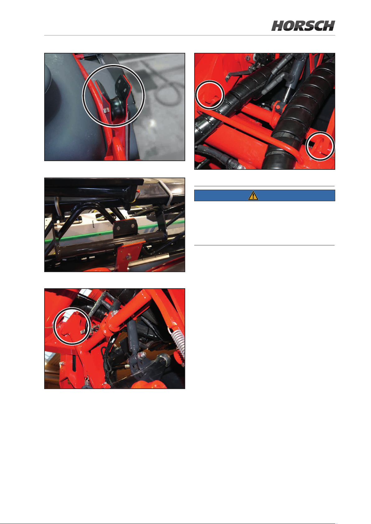
Folding boom rest
Folding boom put down
Parallelogram interlock closed
NOTE
Before setting off for driving on public roads make
sure that the boom rests securely in the boom rest
and both the package lock and the parallelogram
lock as closed.
Parallelogram interlock open
Page 78
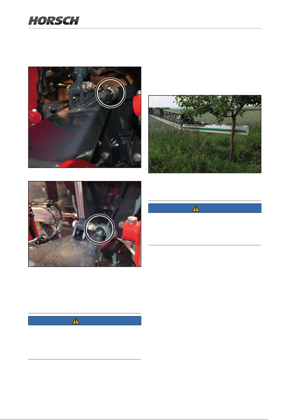
4.6 Slope compensation /
4.7 Collision protection
pendulum lock
Slope compensation / pendulum lock unlocked
The collision protection protects the boom
against damage caused by collision with a solid
obstacle. The joint mechanism enables escaping a collision in travel direction and in opposite
direction.
After the escape movement the collision protection will swing back to initial position.
Slope compensation / pendulum lock locked
Locking takes place automatically when folding in.
Uniform transverse distribution is only achieved
with the slope compensation unlocked.
NOTE
Make sure the slope compensation is locked:
¾ before transport travels!
¾ before unfolding and folding the boom!
NOTE
Collision protection with fully extended working
width. With reduced working width pay atten-
tion to any obstacles around the outside of the
machine!
78 79
Page 79

4.8 Spraying line
4.8.1 Circulation system
The spraying line is made of Ø 25 mm stainless steel pipe. The nozzle control has been
designed as pneumatic single nozzle control for
all versions. Section separation is achieved by
combining the control of several nozzle bodies.
The spray line can be tted with single or multiple
nozzle bodies.
Due to the permanent circulation of the biocatalytic solution through the complete folding boom
while the sprayer is switched o, spraying uid
is permanently applied to the nozzle.
When switching on individual sections or the
entire spraying line for the rst time, the biocatalytic solution is directly and well mixed available.
This circulation successfully prevents the formation of deposits and blockage.
4.8.2 Cleaning nozzle tube and nozzles
The spraying line is cleaned by the circulation
system. The suction side of the sprayer is set
to fresh water for this purpose. The nozzle line
is ushed with clean water.
Switching on the nozzles for about 3 seconds is
sucient to clean them.
Spraying
PS = Pressure Supply
PS
PS
PS
Folding boom left Folding boom rightMiddle section
PS
Circulation
PS = Pressure supply RT = Return ow Tank
RT RT
PS
PS
PS PS
PS
RT
Folding boom left Folding boom rightMiddle section
Page 80
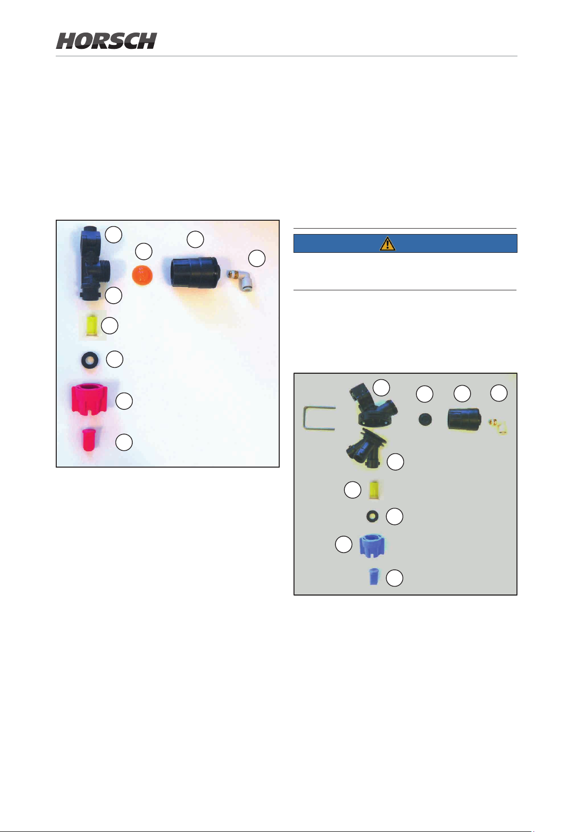
4.9 Nozzle body
4.9.1 Single nozzle body with pneumatic control valve
If a pressure of more than 4 bar is applied to the
compressed air connection (4), the valve will
open and uid can ow out. Without pressure
the valve is closed.
4.9.2 Multiple nozzle body manual 3-fold
The 3-fold nozzle body is recommended if more
than only one nozzle type is to be used. Only
the vertically arranged nozzle will be supplied.
By turning the nozzle body, another nozzle is
brought into use.
In intermediate positions the nozzle body is
switched o.
1
2
8
5
6
9
7
1 nozzle body
2 diaphragm
3 pneumatic control valve
4 compressed air connection
5 nozzle lter (optional)
6 rubber seal
7 nozzle
8 bayonet connection
9 bayonet cap
3
NOTE
4
Flush the spraying lines before turning the 3-fold
nozzle body to another nozzle type!
If a pressure of more than 4 bar is applied to the
compressed air connection (4), the valve will
open and uid can ow out. Without pressure
the valve is closed.
1
2
3
4
8
5
6
9
7
1 nozzle body
2 diaphragm
3 pneumatic control valve
4 compressed air connection
5 nozzle lter (optional)
6 rubber seal
7 nozzle
8 bayonet connection
9 bayonet cap
80 81
Page 81
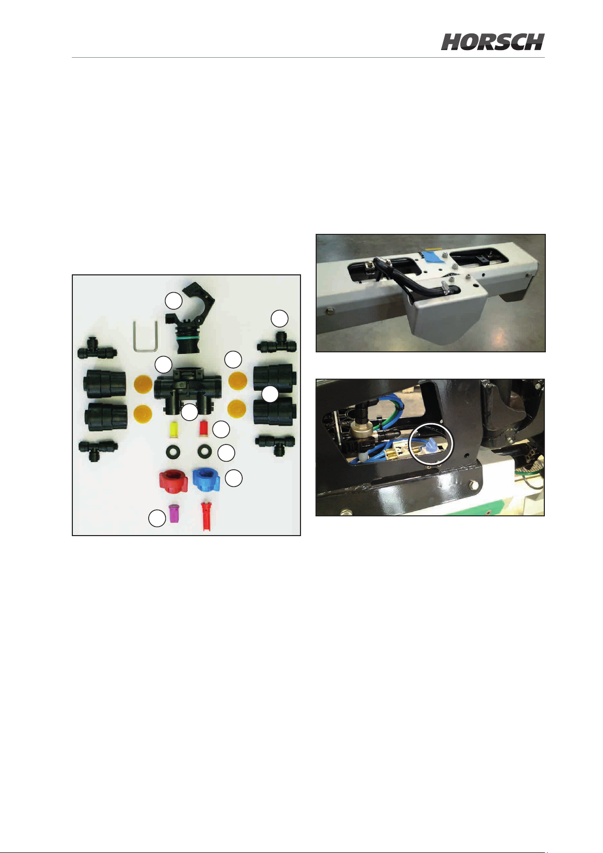
4.9.3 Multiple nozzle body pneumatic
4.9.4 Border nozzles, electric (option)
These multiple nozzle bodies are installed in the
form of dual or 4-fold versions.
In this case it is possible to switch the desired
nozzle from the terminal. You8 may even switch
on several nozzles at a time. The pneumatic
control valves are integrated in the nozzle carrier. If a pressure of more than 4 bar is applied
to the compressed air connection (4), the valve
will open and uid can ow out. Without pressure
the valve is closed.
1
4
10
2
3
8
With a nozzle body division 1-0 and 1-1 with
border nozzle control a border nozzle 25 cm
further towards the outside (exactly at the bor-
der of the eld) is activated electrically via the
terminal. With this version, the switch-over ball
valve must rst be switched on the outside wing
of the folding boom.
Border nozzle
7
1 hinged clamp
2 diaphragm
3 pneumatic control valve
4 compressed air connection
5 nozzle body (optional)
6 rubber seal
7 nozzle
8 bayonet connection
9 bayonet cap
10 nozzle body
5
6
9
Changeover valve (closed)
¾ Changeover valve closed:
The outermost nozzle remains active
¾ Changeover valve open:
The outermost nozzle is deactivated when the
border nozzle is activated.
With a nozzle body division 2-0, 2-1, 2-2, 4-0 and
4-2 the border nozzles are switched only via the
terminal. With this version, no more switch-over
ball valve on the folding boom exists since the
border nozzles on the outermost multiple nozzle body is also engaged. If a border nozzle is
switched on, the main nozzle of the outermost
nozzle body is automatically disabled.
Page 82
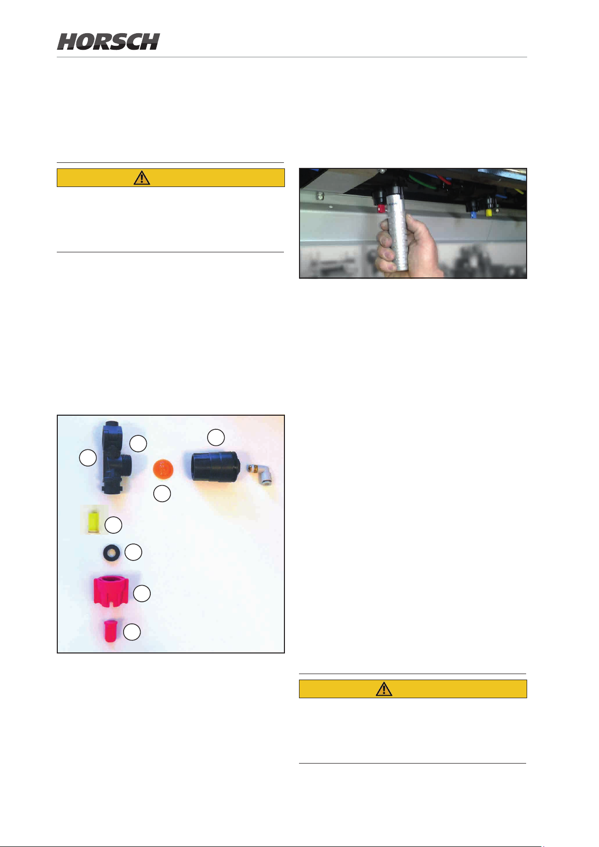
4.10 Assembling and
4.10.2 Changing nozzles
cleaning nozzles
4.10.1 Assembling nozzles
CAUTION
CAUTION Spraying mixture running out!
Apply appropriate protective measures. Catch
running out spraying mixture in a suitable container and dispose of.
1. Insert the nozzle lter (optional) (1) into the
nozzle body (2) from underneath.
2. Insert the nozzle (3) into the bayonet nut (4).
3. Insert the rubber seal (5) above the nozzle.
4. Press the rubber seal into the seat of the
bayonet nut.
5. Attach the bayonet nut to the bayonet connection.
6. Turn the bayonet nut against the end stop.
¾ Turn the nozzles each by approx. 45° (to end
position) to remove and install them.
¾ Use the delivered tool for this purpose:
4.10.3 Cleaning nozzles
The machine is equipped with a compressed
air gun for cleaning or blowing out the nozzles.
¾ Clean the nozzles, if required.
¾ Do not damage nozzles and nozzle lters
when cleaning.
6
2
8
1
5
4
3
Example of a nozzle in individual parts
7
4.10.4 Disassembling the diaphragm valve in case of dripping nozzles
Deposits on the diaphragm seat (6) are the
cause of nozzles dripping after the boom has
been switched o.
In this case clean the corresponding diaphragm
as follows:
1. Unscrew the control valve (7) from the nozzle body (2).
2. Take out the diaphragm (8).
3. Clean the diaphragm seat (6).
4. Assembly takes place in reverse order.
CAUTION
CAUTION Spraying mixture running out!
Apply appropriate protective measures. Catch
running out spraying mixture in a suitable container and dispose of.
82 MF
Page 83

5. Commissioning
This chapter informs you about
¾ the commissioning of the machine.
¾ how to check, whether you are allowed to
attach/connect the machine to your tractor.
NOTE
Before commissioning the machine, the operator must have read and understood the operating instructions.
Do not block any actuators on the tractor, which
serve the purpose of directly executing hydraulic
or electric movements of components, such as
e.g. folding, slewing and pushing processes.
The corresponding movement must automatically stop when the operator releases the corresponding actuator. This does not apply for
equipment which
¾ are continuous or
¾ automatically controlled or
¾ require a oating or pressure position because
of their function
5.1 Check suitability of the
Pay attention to the chapter “Safety” when:
¾ hitching and uncoupling the machine
¾ transporting the machine
¾ working with the machine
NOTE
¾ Use only a suitable tractor for coupling and
transporting the machine.
¾ Tractor and machine must comply with the
instructions of the national road trac regu-
lations.
¾ Vehicle owner (operator) as well as driver
(operating person) are solely responsible for
complying with the statutory regulations of the
national road trac regulations.
WARNING
Danger caused by crushing, shearing, cutting, winding up, being pulled in and caught
in the area of hydraulically or electrically
actuated components.
tractor
WARNING
Risk of accident from breakage during operation,
insucient stability and inadequate steering and
braking ability of the tractor if used for purposes
other than those intended!
Check the suitability of the tractor before you
attach or connect the machine to the tractor.
You may only attach or hitch the machine to a
suitable tractor.
Perform a brake test to check whether the tractor
reaches the required braking delay also with a
connected machine.
Prerequisites for the suitability of
the tractor are in particular:
¾ the permissible total weight
¾ the permissible axle loads
¾ the permissible drawbar load at the hitching
point of the tractor
¾ the load bearing capacity of the assembled
tyres
¾ the permissible trailer load.
You nd these data on the type plate or in the
vehicle registration papers and in the operating
instructions for the tractor.
Page 84

The front axle of the tractor always must be
loaded with at least 20% of the curb weight
of the tractor.
The tractor must be able to achieve the
braking deceleration specied by the tractor
manufacturer, even with attached or hitched
up machine.
NOTE
The actual values for the total weight, tractor
axle loads, tyre load bearing capacity and minimum ballast shall be calculated for the tractor!
5.2 Safeguarding tractor /
machine
WARNING
Danger of crushing, shearing, cutting, cutting o,
being caught, wound up, pulled in and impact
when working on the machine caused by
¾ accidental lowering of lifted, unsecured ma-
chine parts!
¾ accidental starting and unintended rolling of
the tractor/machine combination!
The permissible total weight of the tractor as
specied in the vehicle registration papers must
be greater than the total of
¾ tractor curb weight,
¾ ballasting mass and
¾ total weight of the attached machine or draw-
bar load of the towed machine
Before starting any procedures on the machine
secure both tractor and crop protection sprayer
against accidental starting and unintended rolling away.
All interventions on the machine, such as e.g. as-
sembly work, adjustments, rectication of faults,
cleaning, maintenance and repair, are prohibited
¾ while the machine is driven.
¾ as long as the tractor engine is running with
PTO-shaft pump / hydraulic system connected.
¾ if the ignition key is still in the tractor and the
tractor engine could be accidentally started
with the PTO-shaft pump / hydraulic system
connected.
¾ if tractor and machine are not secured with their
respective parking brake and wheel chocks
against accidental rolling away.
¾ if moveable parts have not been blocked to
prevent unintended movements.
84 85
Page 85
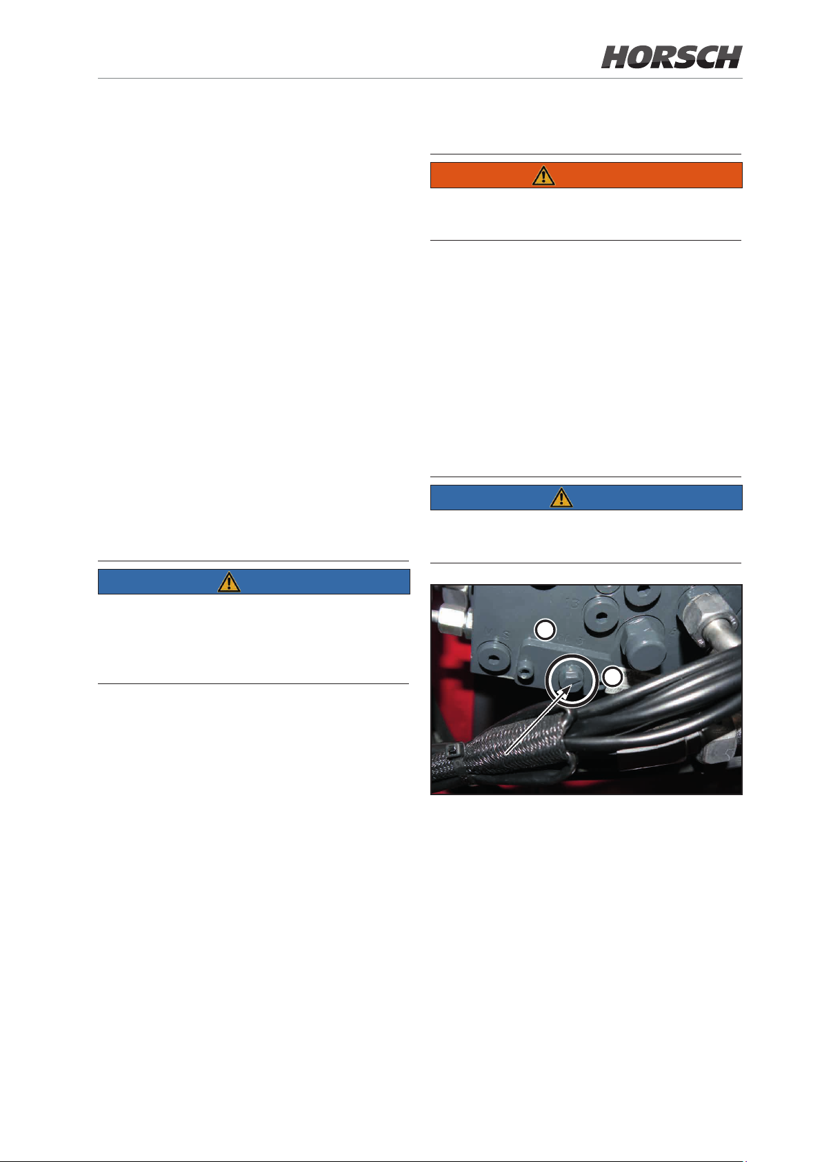
These activities in particular pose danger
by contact with unsecured components.
5.4 Assemble the wheels
¾ Lower raised, unsecured machine / raised,
unsecured machine parts.
This prevents accidental lowering:
¾ Shut down the tractor engine.
¾ Pull out the ignition key.
¾ Apply the parking brake of the tractor.
¾ Secure the machine against unintended roll-
ing away:
• on level ground by applying the parking
brake or wheel chocks.
• on extremely uneven ground or on slopes by
using the parking brake and wheel chocks!
5.3 Initial commissioning of the service brake system
WARNING
Only use approved tyres as specied in the
technical data.
The rims matching the tyres must have an allaround welded rim disc!
Depending on the wheel track, the stop screw
may need to be readjusted on steering axles (see
Chapter "Automatic Ackerman steering").
5.5 Adjusting the hydraulic system on the hydraulic valve block
NOTE
This adjustment must only be made in depressurized condition!
NOTE
Perform test braking in empty and loaded condition of the trailed sprayer and thereby check
the braking behaviour of the tractor and the
coupled sprayer.
We recommend conducting a drawing adaptation between tractor and trailed sprayer in a
professional workshop to ensure optimal braking
behaviour and minimal brake lining wear.
2
1
Setscrew with notch
The hydraulic valve block for the machine is
located at the right front under the covering.
The valve block for the folding boom is located
on the rear of the machine in the centre frame.
The existing tractor hydraulics determines the
adjustment of the hexagon screw on the hydraulic valve block. The notch on the screw indicates
the setting.
¾ Tractor with LS-system: Position CC (1)
¾ Tractor without LS-system: Position OC (2)
Page 86

6. Transport travels
6.1 Safety notes
NOTE
For transport travels pay attention also o the
chapter "Safety notes"!
Check before transport travels:
¾ the proper connection of supply lines
¾ the light system for damage, function and
cleanliness
¾ the brake and hydraulic system for apparent
defects
¾ whether the parking brake is fully released
¾ the function of the brake system
¾ the overall machine for cleanliness
WARNING
Danger of crushing, shearing, cutting, cutting off, being caught, wound up, pulled in
and impact by accidental movements of the
machine.
¾ On foldable machines check the correct locking
of the transport locks.
¾ Secure the machine against accidental move-
ments before starting transport travels.
WARNING
Danger of crushing, cutting, being caught,
being pulled in and impact due to insufcient
stability and tipping over.
¾ Adapt your travel mode so that you are able
to manage the tractor with the hitched up crop
protection sprayer at any time.
Be aware of your own abilities, account for the
road, trac, sight and weather conditions, the
driving characteristics of the tractor and the
impact from the towed machine
WARNING
Danger of breakage during operation, in-
sufcient stability and inadequate steering
and braking ability of the tractor if used for
purposes other than those intended!
¾ These hazards cause severe or even fatal
injuries.
¾ Observe the maximum payload of the towed
machine and the permissible axle and drawbar loads of the tractor.
¾ Observe the permissible total weight of the
machine and the permissible axle and drawbar load.
¾ If necessary drive with the tank only partly
lled.
WARNING
Danger of falling off the machine when riding
on it without permission!
It is not allowed to ride on the machine as a passenger and/or to climb on machines in operation.
Ask people to leave the danger zone before
driving o!
CAUTION
Risk of accident during transport travel with activated trail control or locked tractor control unit.
¾ Trail control must always be deactivated dur-
ing transport travel.
¾ Always set the tractor control unit on the trac-
tor to neutral during transport travel.
¾ Check the transport lock of the folded spraying
boom in transport position to protect against
unintended unfolding.
¾ Check whether the illuviation valve has been
swivelled to the transport position.
¾ The transport lock of the raised access steps
must be checked against unintentional unfolding.
86 87
Page 87
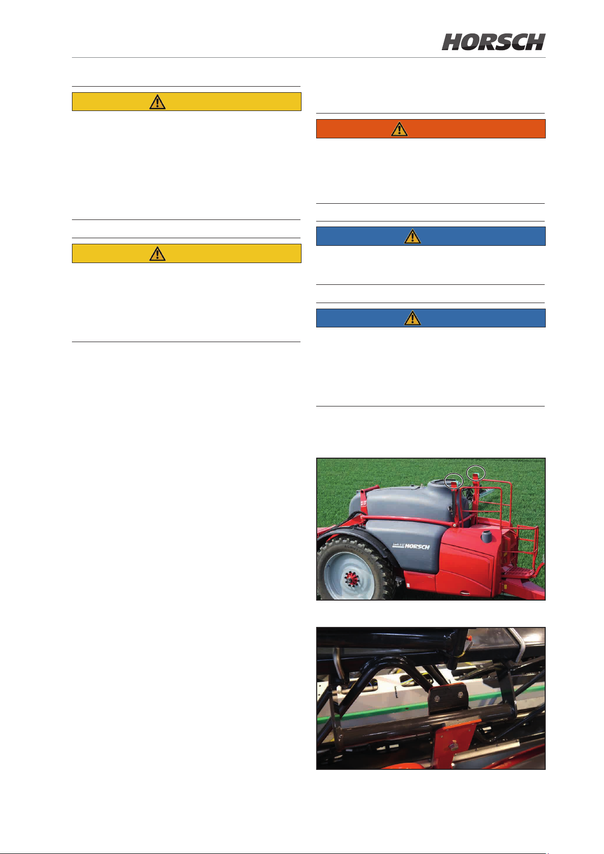
CAUTION
6.2 Transport lock
¾ In order to maintain a sufcient safety distance
to overhead power lines, the total height of
the tractor with towed crop protection sprayer
must not exceed 4 m (13 ft).
¾ When driving or towing on public roads you
must strictly comply with the locally valid trafc regulations.
CAUTION
Danger of accident caused by the machine tipping over!
Bring the steering axle to middle position
(wheels are in line with central axis)!
Automatic Ackerman steering
Bring the steering axle to the centre position
(steering drawbar/wheels are in line with central
axis of the machine).
WARNING
Hazards from crushing and impact for persons
may arise if the folding boom folded in transport
position accidentally unfolds during transport
travel!
NOTE
Driving on public roads is only permitted with
the folding boom folded and placed in its rest!
NOTE
Before starting transport or road travel make sure
that the folding boom rests securely in the folding
boom rest and the package lock is closed.
The parallelogram interlock and the pendulum
lock must also be closed!
For this purpose, select the Steering menu on
the terminal and active Road travel in the submenu or deactivate the steering function via the
multi-function handle.
Automatic Ackerman steering stops automatically when the centre position is reached.
6.2.1 Folding boom rest
Folding boom rest (folding boom unfolded) on both sides
Folding boom resting in transport position
Page 88
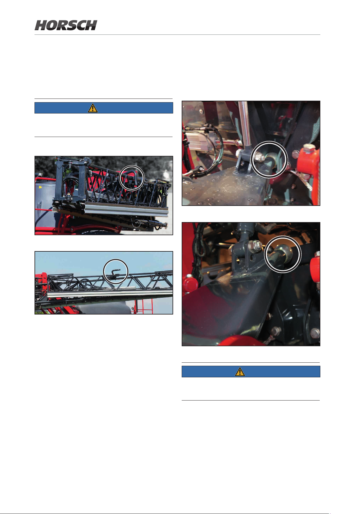
6.2.2 Package lock
The transport lock straps serve to lock the folded
spraying boom in transport position. They prevent accidental unfolding.
NOTE
Before starting transport travel check the interlocking of the folded boom package!
6.2.3 Locking of slope compensation
The pendulum lock is automatically locked when
the folding boom is folded.
Slope compensation locked
Package lock with folded folding boom closed
Package lock open
Unlocking the transport lock
Before the spraying boom is unfolded the transport lock levers automatically swing up thereby
unlocking the spraying boom.
Locking the transport lock
The transport lock levers automatically swivel
down after the spraying boom is folded. The
spraying boom is locked.
Slope compensation open
NOTE
The slope compensation must be locked before
transport travel!
88 89
Page 89
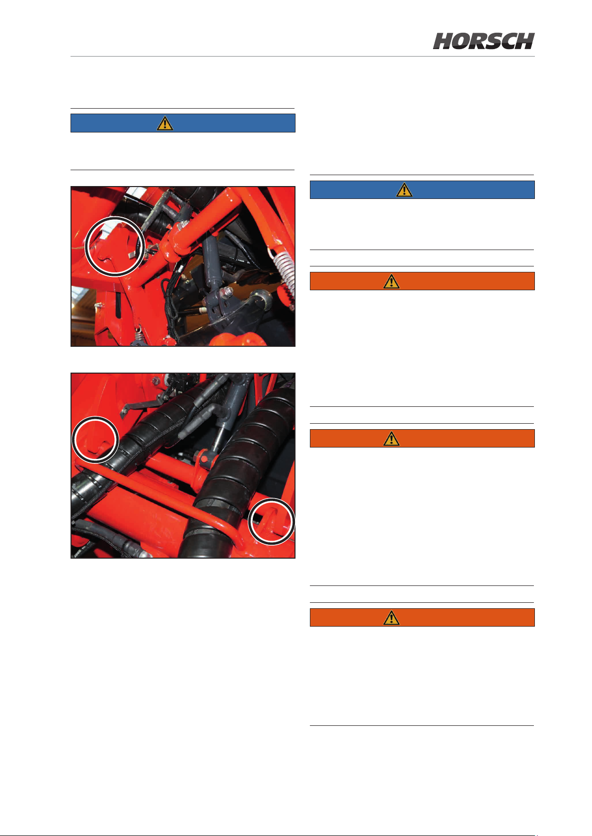
6.2.4 Locking of parallelogram
7. Coupling and
NOTE
Before starting transport travel check the interlocking of the parallelogram!
Parallelogram interlock open
uncoupling the
machine
NOTE
Observe also the chapter "Safety notes"
when coupling and uncoupling the crop
protection sprayer!
WARNING
Danger of crushing through accidental starting
and rolling away of tractor and crop protection sprayer when coupling or uncoupling the
machine!
Tractor and sprayer must be secured against
unintentional starting and rolling away before
entering the danger zone between tractor and
machine for coupling or uncoupling.
Parallelogram interlock closed
WARNING
Danger of crushing between rear of tractor
and machine when coupling or uncoupling the
machine!
Operate the actuating components for the hydraulic system on the tractor
¾ only from the work place provided.
¾ never as long as persons are inside the dan-
ger zone between tractor and crop protection
sprayer.
WARNING
Danger from positive or negative drawbar load
of the machine when
¾ Coupling: First couple up the machine. Then
lift the support to transport position.
¾ Uncoupling: Lower the support rst. Then
uncouple the machine.
Page 90
7.1 Coupling the machine
WARNING
WARNING
Danger of breakage during operation, insuf-
cient stability and inadequate steering and
braking ability of the tractor if used for purposes
other than those intended!
Only connect machine to tractors which are
suitable for this purpose.
WARNING
Danger of crushing between tractor and crop
protection sprayer when coupling!
Before coupling the towed crop protection
sprayer have persons leave the danger zone
between tractor and machine.
Any helpers present should only act as guides
next to tractor and crop protection sprayer and
should only step between the vehicles after
stopped.
WARNING
Persons may be endangered by crushing, being caught, pulled in and impact, if the machine
accidentally disconnects from the tractor!
¾ Use any dedicated facilities for connecting
tractor and machine as intended.
¾ Check visually whether the connection is cor-
rectly interlocked.
Danger caused by power supply failure between
tractor and machine caused by damaged supply lines!
When coupling the supply lines, pay attention
to the routing of the lines:
¾ Supply lines must be free of tension, kinking
or friction and easily follow all movements of
the attached or towed machine.
¾ The supply lines should not rub against for-
eign parts.
Procedure
1. Instruct persons to leave the danger zone
between tractor and crop protection sprayer
before backing the tractor up to the machine.
2. Back up the tractor to the crop protection
sprayer and secure against unintentional
starting and rolling away.
3. Connect the machine to the adjustable drawbar or ball head coupling on the tractor.
4. Connect hydraulic hoses, brake system lines
and cables for lighting.
5. Connect the sprayer controls to the ISOBUS
socket on the tractor.
6. Connect the PTO-shaft pump to the tractor
(optional).
7. Operate the control unit for the parking support and fold in the support.
8. Remove the wheel chocks.
9. Release the parking brake of the crop protection sprayer by means of the crank.
CAUTION
Danger of damage to the high pressure cleaner
NOTE
and loss of oil!
When using tractors without Load-Sensing hy-
draulics (LS), connect the lines for supply and
return ow correctly.
Check all plug-and-socket connections (hydraulic, electric and pneumatic) for cleanliness and
rm seating.
Dirty connectors will contaminate the owing
media. The connectors therefore become worn
and this results in malfunctions and failures in
the connected assembly groups.
90 91
Page 91

7.2 Uncoupling the machine
WARNING
7. Disconnect brake lines.
8. Close the coupling heads of the supply and
brake lines.
9. Uncouple the crop protection sprayer from
the tractor.
Risk of accident by uncoupling the crop protection sprayer with the folding boom unfolded!
Negative drawbar load can cause the machine
to tip over!
WARNING
Danger of crushing, cutting, being pulled in,
being caught and impact caused by inappropriate stability and tipping over of the hitched up
machine!
When uncoupling the machine you should
always ensure sucient free space in front of
the machine, so that you will be able to back
the tractor up to the machine when you have to
couple the next time.
WARNING
Danger of crushing between tractor and crop
protection sprayer when uncoupling!
Before uncoupling the towed sprayer have
persons leave the danger zone between tractor
and machine.
Any helpers present should only act as guides
next to tractor and crop protection sprayer and
should only step between the vehicles after
stopped.
Procedure
10. Drain water from the air reservoir and close
the hose couplings, if the machine is not used
for a longer period of time.
11. With hydraulic brakes the pulling cable of
the parking brake must be detached from
the tractor.
7.2.1 Manoeuvring the uncoupled machine
DANGER
Special caution must be exercised during manoeuvring work with released service brake
system since the towed sprayer is now braked
solely by the shunting vehicle.
The machine must be connected with the shunting vehicle before the releasing valve on the
trailer brake valve is operated.
The shunting vehicle must be braked.
NOTE
If the air pressure inside the air vessel drops below
3 bar (e.g. because of several actuations of the
releasing valve or leakages in the brake system),
the service brake system can no longer be operated via the releasing valve.
1. Park the empty machine on a horizontal parking area with solid ground.
2. Engage the parking brake of the crop protection sprayer by means of the crank.
3. Secure the machine with wheel chocks
against rolling away.
4. Extend the hydraulic parking support.
5. Disconnect the PTO-shaft pump from the
tractor (optional).
6. Disconnect hydraulic and electrical connections and hook into bracket devices.
To release the service brake:
¾ ll the air vessel.
¾ completely drain the brake system through
the drainage valve on the air vessel.
Page 92

1. Connect the machine to the shunting vehicle.
2. Brake the shunting vehicle.
3. Remove the wheel chocks and release the
parking brake by means of the crank.
4. only for pneumatic brake system:
Press in the button on the releasing valve
against the stop position.
¾ The service brake system comes loose and
the machine can be manoeuvred.
Once the shunting process is nished, pull
out the button on the releasing valve to the
stop position.
¾ The accumulated pressure from the air ves-
sel once again brakes the trailed sprayer.
5. Brake the shunting vehicle once again after
the shunting process is nished.
6. Pull the parking brake again by means of the
crank and secure the machine against rolling
away using wheel chocks.
7. Uncouple the machine from the shunting
vehicle.
92 MF
Page 93

8. Working with the machine
NOTE
Pay attention to the separate operating instructions for the control terminal.
When working with the machine pay attention
to the notes in the following chapters:
¾ Warning signs and other markings on the
machine
¾ Safety notes
WARNING
Danger of breakage during operation, in-
sufcient stability and inadequate steering
and braking ability of the tractor if used for
purposes other than the ones the machine
is intended for.
Observe the maximum payload of the towed
machine and the permissible axle and drawbar
loads of the tractor. If necessary drive with the
solution tank only partly lled.
WARNING
Danger of crushing, cutting, cutting off,
being pulled in, being caught and impact
caused by inappropriate stability and tipping
over of the tractor with the towed machine!
Adapt your travel mode so that you are able to
manage the tractor with the towed crop protection
sprayer safely at any time. Be aware of your own
abilities, account for the road, trac, sight and
weather conditions, the driving characteristics
of the tractor and the inuences of the towed
machine.
WARNING
Danger of crushing, shearing, cutting, cutting off, being caught, being pulled in and
impact caused by
¾ accidental lowering of lifted, unsecured
machine parts.
¾ accidental starting and unintended rolling
of the tractor/machine combination.
Secure the tractor combination against unintended starting and rolling away before faults on
the machine can be rectied.
Before entering the danger zone wait until the
machine has come to a halt.
WARNING
Applies only to machines where the oil supply
is provided by a PTO-shaft pump.
Risk by thrown out, damaged components for
operator and third parties can result from impermissibly high rotary speeds of the tractor's
PTO-shaft!
Observe the permissible drive speed of the
machine before you switch on the PTO-shaft
of the tractor.
Page 94

WARNING
8.1 Preparing for spraying
Danger caused by accidental contact with crop
protection agents / spraying mixture!
Wear personal protective outt
¾ when preparing the spraying mixture.
¾ when cleaning / replacing spray nozzles.
¾ during all work for cleaning the crop protection
sprayer after spraying operation
When wearing the required protective clothing
you should always follow the information of
the manufacturer, the product information, the
instructions for use, the safety data sheet or the
operating instructions for the crop protection
product to be used.
NOTE
Personal protective outt consists of:
¾ chemicals resistant gloves
¾ a chemicals resistant overall
¾ waterproof shoes
¾ face protection
¾ respirator
¾ safety goggles
¾ skin protection agent, etc.
Protective gloves shall be worn when
¾ handling crop protection agents.
¾ working on the contaminated crop protection
sprayer.
¾ cleaning the crop protection sprayer.
Wash the protective gloves with clean water
from the fresh water tank
¾ immediately after any contact with crop pro-
tection products.
¾ before taking o the protective gloves.
NOTE
Basic prerequisite for the proper application
of crop protection agents is the proper function of the crop protection sprayer.
¾ Have the crop protection sprayer regularly
tested on a test stand. Rectify apparent faults
immediately. Have the crop protection sprayer
checked, as requested.
¾ Before starting spraying check the following
machine data in the control terminal:
• the permissible spraying pressure range for
the installed spraying nozzles.
• the value for “Pulses per 100 m”.
¾ Use all specied lters.
¾ Clean the lters at regular intervals.
Trouble free operation of the crop protection
sprayer is only ensured with optimal ltration
of the spraying mixture. Appropriate ltering
considerably inuences the treatment success
of the crop protection measure.
¾ Pay attention to the permissible lter combina-
tions or mesh sizes.
The mesh sizes of pressure lters and nozzle
lters must always be smaller than the nozzle
opening of the nozzles used.
The standard pressure lter element used in
the pressure lter has a mesh size of 0.18
mm with 80 meshes/inch. This pressure lter
element is adequate for a nozzle size from 02'.
The pressure lter element with 100 meshes/
inch is required for nozzle sizes '015' and '01'
(optional equipment).
¾ Please remember that the use of pressure
lter elements with 100 meshes/inch will have
the eect that with some crop protection products active components may be ltered out. If
in doubt, contact the crop protection product
manufacturer.
94 95
Page 95

¾ Generally clean the crop protection sprayer
before placing another crop protection agent.
¾ Flushing nozzle line and nozzles:
• with each nozzle change
• before the installation of other nozzles
• before turning the three-fold nozzle head to
another nozzle.
¾ Couple the crop protection sprayer properly
to the tractor (see chapter Coupling and uncoupling the machine)!
¾ Take appropriate action if an error message ap-
pears in the display during spraying operation.
¾ Check the displayed spraying pressure during
spraying operation.
¾ Make sure that the displayed spraying pres-
sure does under no conditions deviate from
the specified spraying pressure from the
spraying table by more than ±25%, e.g. when
changing the application quantity
¾ More signicant deviations from the specied
spraying pressure will adversely aect the
optimal treatment success of the crop protection measure and/or cause environmental
damage.
¾ Reduce or increase the travel speed, until the
permissible spraying pressure range (of the
intended spraying pressure) is reached again.
¾ Never spray the spraying mixture tank com-
pletely empty (this does not apply for the end
of the spraying operation). Fill up the spraying
mixture tank at the latest when a lling level
of approx. 50 litres is reached.
8.2 Preparing the spraying mixture
DANGER
Danger caused by accidental contact with
crop protection products and/or spraying
mixture!
When preparing spraying mixture there is the
highest risk of coming into contact with crop
protection product.
Strictly wear safety gloves and appropriate
protective clothes!
¾ Generally ush the crop protection agents
through the induction hopper into the spraying mixture tank.
¾ Swing the illuviation valve to lling position,
before crop protection agent is lled into the
induction hopper.
¾ Follow the safety regulations when handling
crop protection agents and when preparing
the spraying mixture: Read the instructions
for use for the crop protection agent.
¾ Do not prepare the spraying mixture in the
vicinity of wells or surface waters.
¾ Avoid leakages and contamination with crop
protection products and / or spraying mixture
by acting appropriately and by wearing appropriate body protection.
¾ Do not leave the prepared spraying mixture,
unused crop protection products as well as
contaminated crop protection product canisters and the uncleaned crop protection
sprayer unattended, to avoid dangers for
third parties.
¾ Protect contaminated crop protection product
canisters and contaminated crop protection
sprayer against precipitation.
¾ Ensure sucient cleanliness during and after
spraying mixture preparation to keep the risks
as low as possible (e.g. thoroughly wash o and
dispose of used gloves. Dispose of washing
water and cleaning uid in a proper manner).
Page 96

NOTE
Besides the generally valid information listed
hereunder, you should also follow the product-
specic procedures described in the instructions
for use of the crop protection agents!
¾ Pay attention to the prescribed water and
preparation application quantities as per
instructions for use for the crop protection
agent.
¾ Follow the instructions for use for the prepara-
tion and the specied precautions!
¾ Carefully determine the required lling or re-
lling quantities to avoid residual quantities,
because an environmentally friendly disposal
of residual quantities is very dicult.
Use the "Filling table for residual areas" to
calculate the required relling quantity for
the last spraying mixture tank lling. In this
case subtract the technical, undiluted residual
quantity in the spray boom from the calculated
relling quantity.
¾ In this context see chapter "Filling table for
residual areas"
¾ Thoroughly rinse out emptied preparation
containers (e.g. with canister ushing agent)
and mix in the ushing water to the spraying
mixture!
General procedure
1. Determine the required water and preparation
application quantity as per instructions for use
for the crop protection agent.
2. Calculate the lling or relling quantity for the
area to be treated.
3. Fill half of the spraying mixture tank with
water.
4. Switch on the agitator.
5. Add the calculated preparation quantity.
6. Top up the missing amount of water.
7. Before starting spraying stir up the spraying
mixture as instructed by the crop protection
product manufacturer.
96 97
Page 97

8.2.1 Calculating lling / relling
quantities
NOTE
Use the "Filling table for residual areas" (chapter
8.2.2) to calculate the required relling quantity for
the last spraying mixture tank lling.
Example 1: Filling quantities
Example 2: Addition of product, area
The following is known:
Nominal container capacity 1000 l
Residual quantity in container 200 l
Required water 500 l/ha
Recommended concentration 0.15 % l/l or kg/l
Question 1:
How many l or kg preparation must be metered
for one container lling?
The following is known:
Nominal container capacity 1 000 l
Residual quantity in container 0 l
Required water 400 l/ha
Required amount of chemical per ha
Product A 1.5 kg
Product B 1.0 l
Question:
How many l of water, how many kg or product
A and how many l of product B do you have to
ll in, if the area to be treated is 2.5 ha?
Calculation formula and solution
Component [quantity/ha] x area [ha]
= required quantity [l] or [kg]
Water: 400 l/ha x 2.5 ha = 1000 l
Product A: 1.5 kg/ha x 2.5 ha = 3.75 kg
Product B: 1.0 l/ha x 2.5 ha = 2.5 l
Calculation formula and answer to
question 1:
Water rell quantity [l] x concentration [%]
100
= product addition [l] or [kg]
(1000-2000) [l] x 0.15 [% l/l or kg/l]
100
= 1.2 [l] or [kg]
Question 2:
How big is the area to be treated in ha, which can
be treated with one lling, if the container can
be emptied down to a residual quantity of 20 l?
Calculation formula and answer to
question 2:
Available amount of chemical [l] – Residual
quantity [l]
Required water [l/ha]
= area [ha]
1000 [l] (rated volume) – 20 [l] (residual quantity)
500 [l/ha] (required water)
= 1.96 [ha]
Page 98
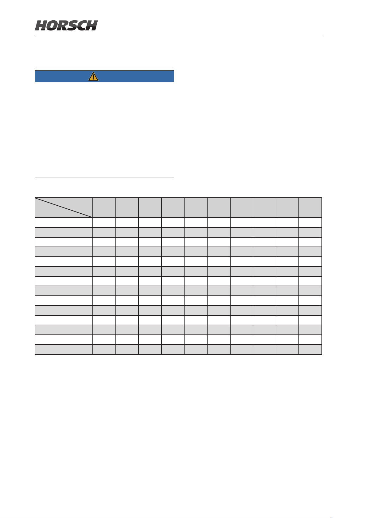
8.2.2 Filling table for residual areas
NOTE
¾ Use the "Filling table for residual areas" to
calculate the required relling quantity for the
last spraying mixture tank lling.
¾ Subtract the residual quantity in the spraying
line from the calculated relling quantity!
¾ See also chapter "Spraying line"
¾ The specied relling quantities apply for an
application quantity of 100 l/ha.
¾ For other application quantities the relling
quantity may multiply.
Rell quantity [l] for spray boom:
Working width [m]
Travel distance [m]
18 m 20 m 21 m 24 m 27 m 28 m 30 m 32 m 33 m 36 m
10 2 2 2 2 3 3 3 3 3 4
20 4 4 4 5 5 6 6 6 7 7
30 5 6 6 7 8 8 9 10 10 11
40 7 8 8 10 11 11 12 13 13 14
50 9 10 11 12 14 14 15 16 17 18
60 11 12 13 14 16 17 18 19 20 22
70 13 14 15 17 19 20 21 22 23 25
80 14 16 17 19 22 22 24 26 26 29
90 16 18 19 22 24 25 27 29 30 32
100 18 20 21 24 27 28 30 32 33 36
200 36 40 42 48 54 56 60 64 66 72
300 54 60 63 72 81 84 90 96 99 108
400 72 80 84 96 108 112 120 128 132 144
500 90 100 105 120 135 140 150 160 165 180
Example: Rell quantity
Remaining residual distance: 100 m
Application quantity: 100 l/ha
Working width: 21 m
Residual quantity in spraying line: 5.2 l
1. Use the lling table to calculate the relling
quantity.
In the example the relling quantity is 21 l.
2. Subtract the residual quantity in the spraying
line from the calculated relling quantity.
Required relling quantity: 21 l - 5.2 l = 15.8 l
98 99
Page 99

8.3 Filling with water
NOTE
When lling, pay attention to the permissible
payload of your crop protection sprayer!
When lling the crop protection sprayer you
must strictly consider the dierent specic den-
sities [kg/l] of the individual uids!
Fluid Density [kg/l]
Water 1
Carbonyl diamide 1.11
Ammonium nitrate -
carbonyl diamide solution
NP-solution 1.38
Example:
With 4000 l AHL the spraying mixture tank is filled with a mass of
4000 l x 1.28 kg/l = 5120 kg!
WARNING
Danger for persons / animals due to accidental contact with spraying mixture when
lling the spraying mixture tank!
¾ Wear your personal protective outfit when
processing crop protection agents or draining
spraying mixture from the spraying mixture tank.
The required protective outt depends on the
information of the manufacturer, the product
information, the instructions for use, the safety
data sheet or the operating instructions for the
crop protection product to be used.
¾ Before each lling check the crop protection
sprayer for damage, e.g. leaking container
and hoses as well as the correct positioning
of all operating elements.
¾ Never leave the crop protection sprayer unat-
tended during lling.
¾ Never exceed the nominal capacity when ll-
ing the spraying mixture tank.
1.28
¾ Never exceed the permissible payload of the
crop protection sprayer when lling the spraying mixture tank.
¾ Pay attention to the specic weight of the uid
to be lled in.
¾ When lling keep an eye on the level gauge to
avoid overlling of the spraying mixture tank.
¾ When lling the spraying mixture tank pay
attention to sealed surfaces, so that no wash
runs into the sewer system.
¾ No foam should escape from the spraying
mixture tank during lling.
A large cross-section funnel that reaches
down to the bottom of the spraying mixture
tank, most eectively prevents the formation
of foam.
Adding an anti-foaming agent will also prevent
the formation of foam in the spraying mixture
tank.
¾ When lling the spraying mixture tank do
not make a direct connection between the
lling hose and the contents in the spraying
mixture tank!
Only this prevents back siphoning or back
pressing of spraying mixture into the drinking
water line.
¾ Fasten the end of the lling hose at least
10 cm above the lling opening in the spraying mixture tank.
The free outow created this way oers the
highest level of safety against the back ow of
spraying mixture into the drinking water line.
¾ Fill the spraying mixture tank only with the
lling screen in place.
NOTE
The most harmless way of lling is at the
edge of the eld from the water tanker (if
possible make use of a natural inclination).
Depending on the crop protection product
used this lling method is not allowed in
water protection zones! You should in any
case ask the "Water board"!
Page 100
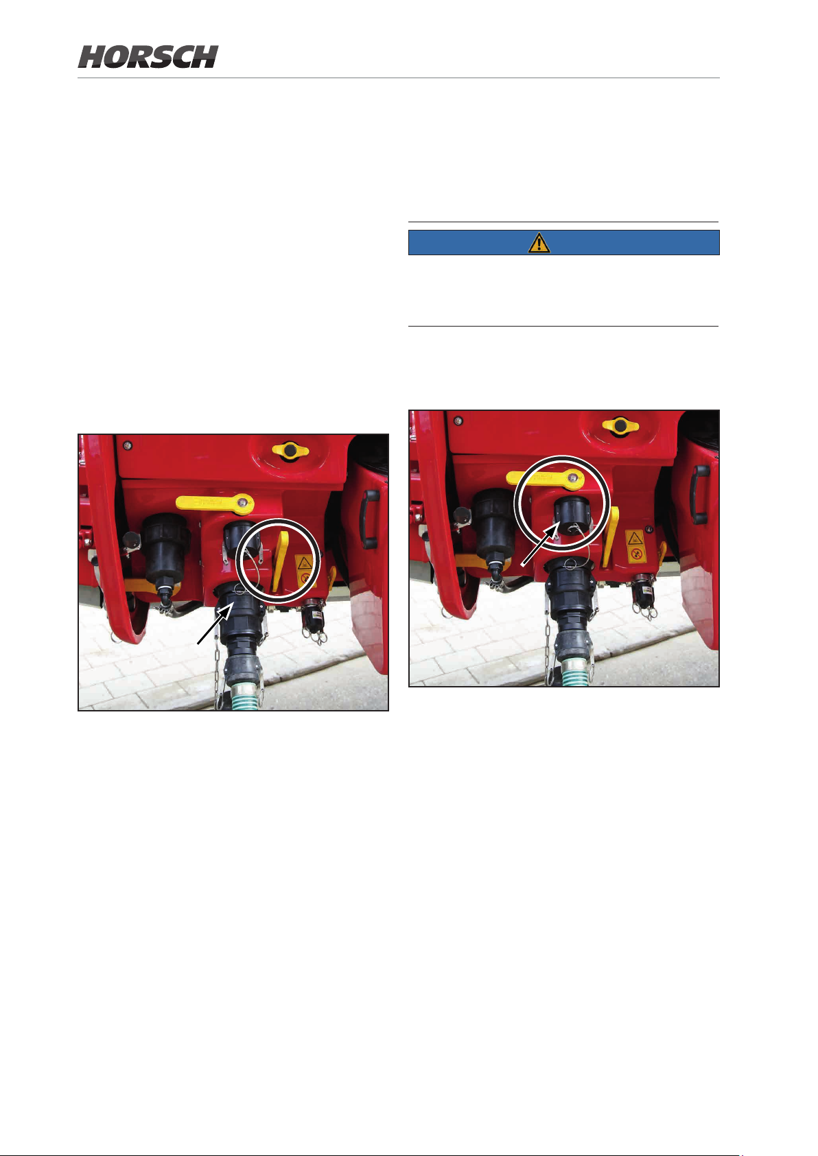
8.3.1 Filling the spraying mixture
tank through the ller connection
Pay attention to the applicable regulations for
lling the spraying mixture tank through the suction hose from open water tapping points (see
also chapter "Using the machine").
8.3.2 Direct lling (external lling)
At the direct lling connection uid from an
external tank can be pressed directly into the
solution tank.
NOTE
¾ Always keep an eye on the level gauge while
lling.
¾ Stop lling the spraying mixture tank at the
latest
• when the lling limit is reached.
• before the permissible payload of the crop
protection sprayer is exceeded by the lled
in amount of uid.
Danger caused by overlling the spraying
mixture tank. No automatic shut-down when
the tank is full!
¾ Pay attention to the max. permissible ow
rate. This must not exceed 1 m3/min.
Filling connection for spraying mixture tank
1. Enter the desired container content in the
terminal.
2. Connect the suction hose to the lling con-
nection.
3. Open the ller valve.
4. Start lling via terminal.
5. The suction tting switches o automatically
when the desired lling level is reached
The lling process can be aborted at any time.
6. Uncouple the suction hose.
7. Close the lling valve.
8. Close the connection with the cap.
Direct lling connection
100 101
 Loading...