

Page 1

*UM206030*
Sheet Cutter
SmartStacker
User’s Manual
Important Information
- This manual is designed to help you to operate and maintain the Smart-
Stacker. Please read and understand this manual, and keep it in a safe and
convenient place.
- Do not operate the SmartStacker until you read and understand the in-
structions in this manual.
- Horizon International Inc. shall not be liable for incidental consequential
damages resulting from: improper or inadequate maintenance by the cus-
tomer, unauthorized modication or misuse, or operation outside of the
environmental specications for the product.
- Horizon International Inc. pursues a policy of continuing improvement in
design and performance of the product. Therefore, the product design and
specications are subject to change without prior notice and without our
legal obligation.
- All rights are reserved. No part of this manual may be photocopied, repro-
duced or translated to another language without the prior written consent
of Horizon International Inc.
170107/HN,CF,AT,RN/IDCS5.5/ICS5/PXI
UM206030-10(000)
Page 2
Safety Precautions
Safety precautions are indicated in this manual as follows:
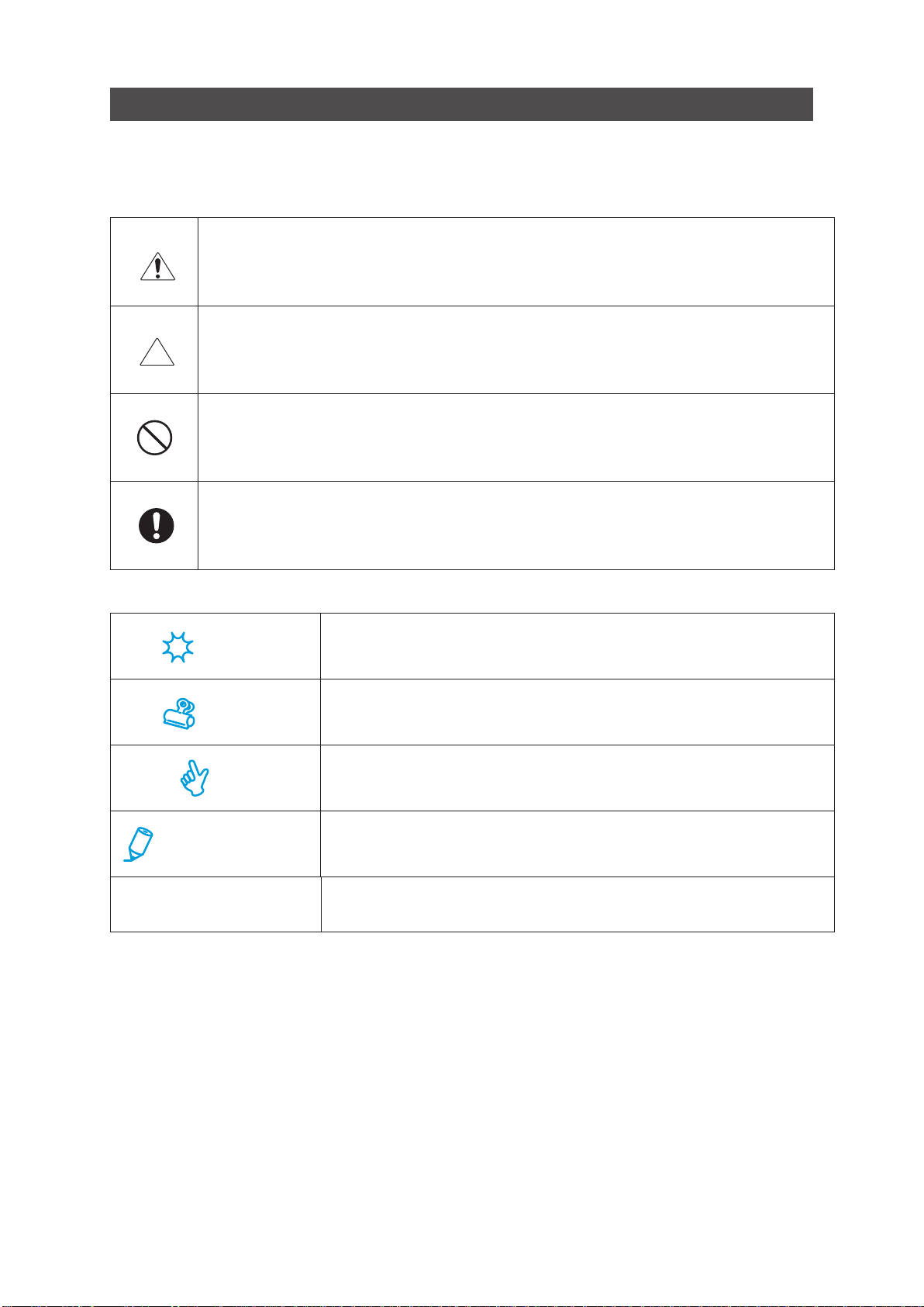
The term WARNING indicates a potentially hazardous situation which, if not avoided,
could result in death or serious injury.
The term CAUTION indicates a potentially hazardous situation which, if not avoided,
may result in serious injury, or damage to the machine.
This symbol indicates a note which includes important information. Follow the note to
operate the machine safely.
This symbol indicates a prohibited action. Do not perform any prohibited action.
This symbol indicates an essential procedure. Follow the procedure to operate the machine safely.
This will help you to avoid an incorrect operation which may cause
Important
Attention
Note
Additional Information
➡
- Horizon International Inc. cannot anticipate every possible situation that might involve a potential
hazard. Therefore, the instructions in this manual and warning labels on the machine are not allinclusive.
- All equipment shall be locked out or tagged out to protect against accidental or inadvertent operation
when such operation could cause injury to personnel. Do not attempt to operate any switch, valve,
or other energy isolating device when it has been locked or tagged out.
- Do not operate the machine when any covers are removed.
- Some of the drawings in this manual show the machine with the covers removed to help in
explaining the details inside the machine.
problems with the machine, or make it necessary to go back to a
previous step.
This explains functional limitations and restrictions on the operation
of the machine.
This indicates a helpful hint.
This indicates additional information which will help you to operate
the machine efciently.
This explains what the machine will do after you operate it as instructed.
2 SmartStacker User's Manual
Page 3
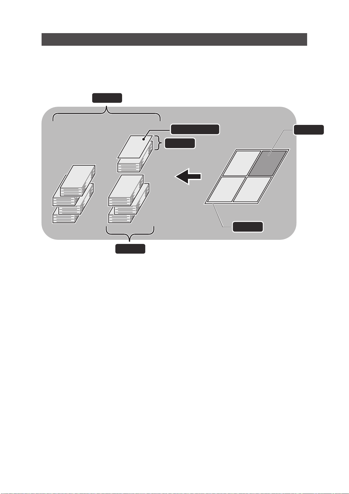
Glossary
The drawing below shows the terms we will use in this manual.
Job
Stack
Page / Piece
Block
Sheet
26030
10101A1
Page
3SmartStacker User's Manual
Page 4
Basic Safety Precautions
WARNINGS for Operation
Keep your hands and ngers outside of the safety cover and away from any moving parts
while the machine is running. Otherwise, moving parts can cause severe personal injury.
Work alone when you operate the machine. Letting someone else operate the machine
could cause it to start suddenly without warning, causing severe personal injury.
Do not remove or bypass any safety features. Without these protective features, moving
parts can cause severe personal injury.
Be sure all other operators are clear of the machine before turning the handwheel. If someone else has their hands in the machine, turning the handwheel could cause personal injury.
As the working condition may include exposure to high noise levels which can lead to hearing damage, the employer and operator should ensure that any necessary hearing protection is provided and used by the operator and others in the work area.
Only for optional Sheet Feeder :
• Do not stare into beam of sheet edge indicator (class 1 laser product*1).
Otherwise, light beam can cause severe personal injury.
*1 This laser meets the IEC standards, 60825-1: 2007,class 1 LASER product.
• Use of controls or adjustments or performance of procedures other than these specied
here in may result in hazardous radiation exposure.
Sheet Edge Indicator
4 SmartStacker User's Manual
Page 5
WARNINGS for Operation
When you lower the feed table, do not place your feet under the table.
Press the Emergency Stop button before turning the drive handwheel. If the machine
accidentally starts suddenly, this can cause severe personal injury.
Turn off the power switch before adjusting the machine unless instructed otherwise. If the
Start button is pressed when the power is on, the machine may cause severe personal injury.
CAUTIONS for Operation
If you turn off the Power switch, wait about ten seconds before turning it on again. Otherwise, a circuit board may be damaged.
If a jam occurs, remove all the jammed sheets before you start the operation again. Otherwise the machine may be damaged.
Do not use the machine for any improper purpose. Otherwise, the performance of the machine cannot be guaranteed.
5SmartStacker User's Manual
Page 6
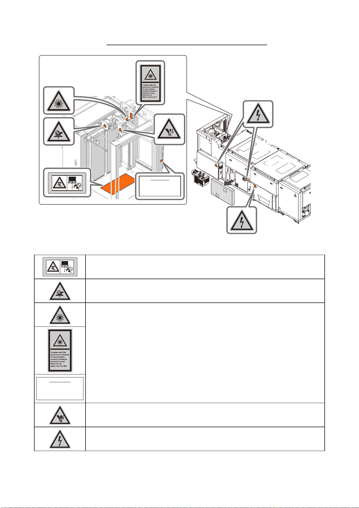
Sheet Feeder
Warning Label Locations and Meanings
Feeder
1st Regist
Unit
Identification Label
Taiyo Seiki Co., Ltd.
1600 Aza-Shironoshita, Asahi, Shin-asahi-cho,
Takashima, Shiga 520-1501, Japan
Biwako Factory
Manufactured: 1.2014
1st Process
Unit
Identification Label
Taiyo Seiki Co., Ltd.
1600 Aza-Shironoshita, Asahi, Shin-asahi-cho,
Takashima, Shiga 520-1501, Japan
Biwako Factory
Manufactured: 1.2014
Do not get into under the feed table. Otherwise, you may be injured
Do not approach your hands and ngers while the roller is rotating.
Otherwise your hands and ngers may be caught by the rotating roller.
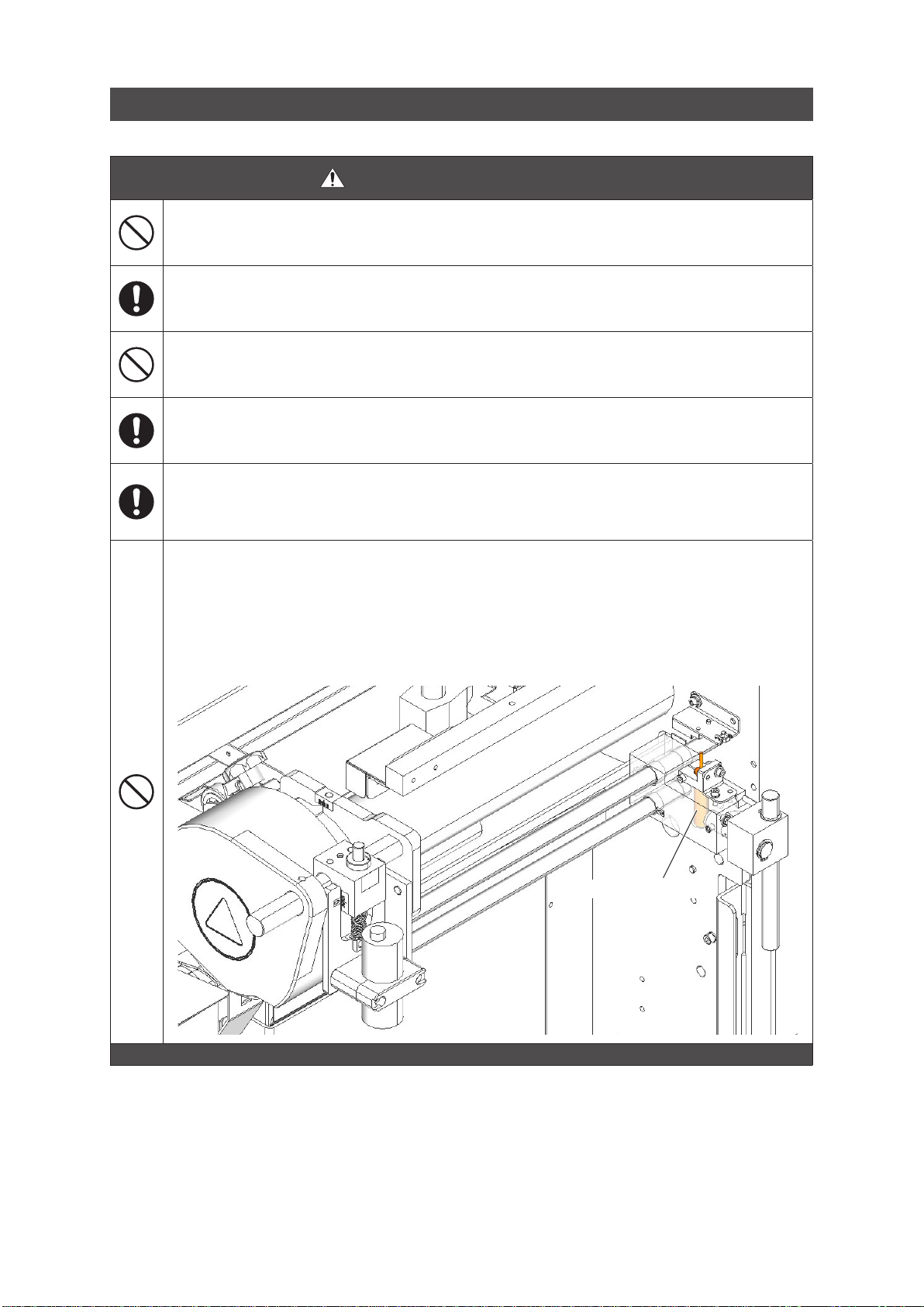
Do not stare into beam of sheet edge indicator (class 1 laser product*1).
Otherwise light beam can cause severe personal injury.
*1 This laser meets the IEC standards, 60825-1: 2007, class 1 LASER product.
Laser Diode Wavelength: 625-640 nm
Maximum Power: 5 mW
Do not approach your hands and ngers to the suction head while the feed table is
moving. Otherwise your hands and ngers may be caught by the suction head.
There are electric parts inside. Take care when opening the cover.
Otherwise, high voltage can cause severe personal injury.
6 SmartStacker User's Manual
Page 7
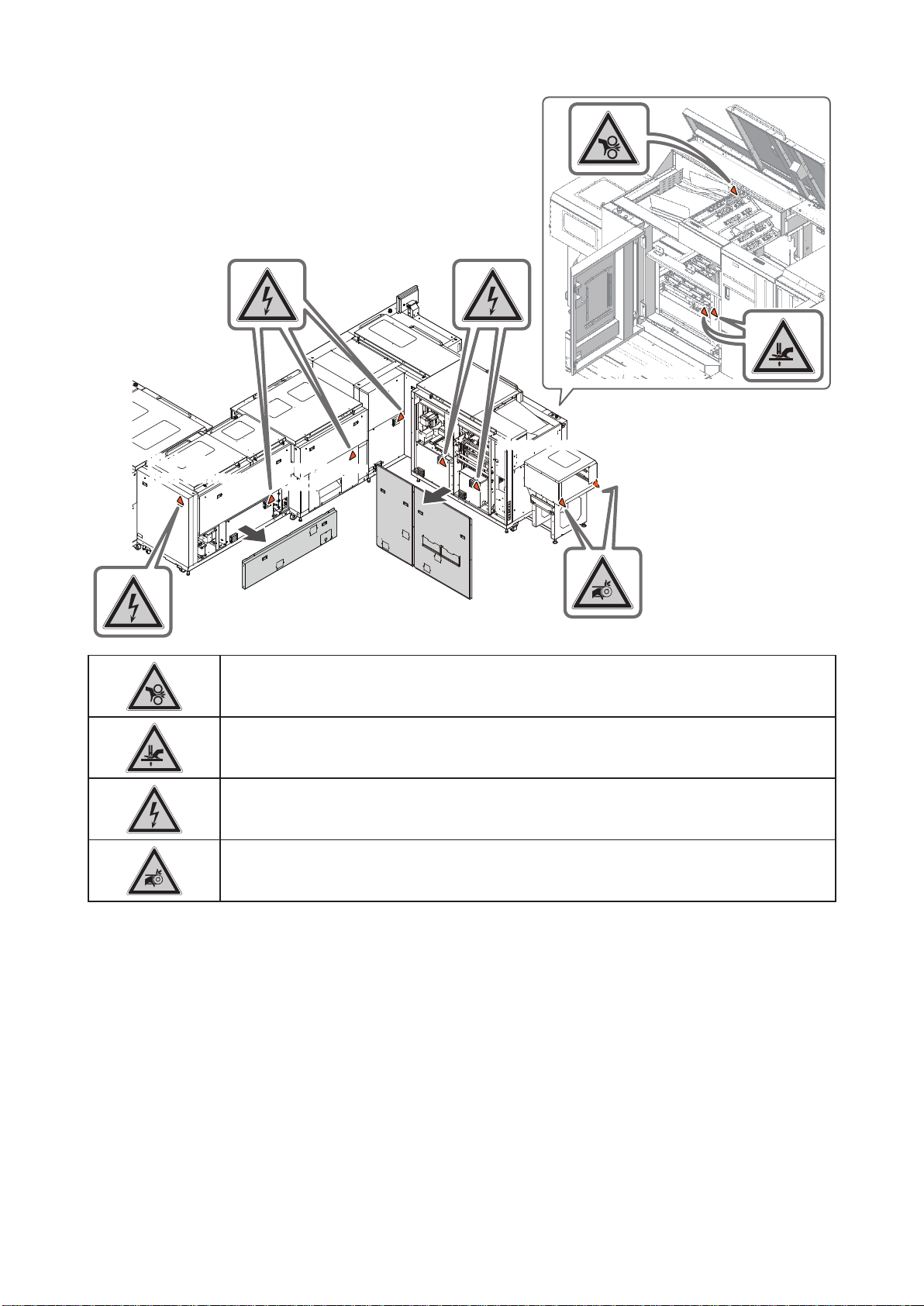
90-degree
Turn Conveyor
Keep your hands and ngers away from the rollers while they are turning.
Otherwise your hands and ngers may be caught by the moving rollers.
Merge
Conveyor
Merge Stacker
Merge Stacker
2nd Process
Unit
Do not approach your hands and ngers while the stack table of the Merge Stacker is
moving. Otherwise your hands and ngers may be caught by the stack table.
There are electric parts inside. Take care when opening the cover.
Otherwise, high voltage can cause severe personal injury.
Keep your hands and ngers away from the belts and rollers while the belts are
moving. Otherwise your hands and ngers may be caught by these parts.
7SmartStacker User's Manual
Page 8

Contents
Important Information ........................................................................................................................1
Safety Precautions ............................................................................................................................2
Glossary ............................................................................................................................................3
Basic Safety Precautions...................................................................................................................4
Warning Label Locations and Meanings ...........................................................................................6
1 Machine Description
1-1 Features of the Machine .....................................................................................14
1-1-1 SmartStacker Conguration ................................................................................14
1-1-2 Directions described in this manual .....................................................................15
1-1-3 Sheet Flow ...........................................................................................................16
1-1-4 Delivery ................................................................................................................19
1-1-5 Supported Jobs ...................................................................................................22
1-1-6 Capability of Each Line ........................................................................................26
1-1-7 The Role of Panels of the SmartStacker and the FLC ........................................27
1-2 SmartStacker Screen Descriptions .....................................................................28
1-2-1 Run - Main Screen - Part 1 ..................................................................................28
1-2-2 Run - Main Screen - Part 2 ..................................................................................29
1-2-3 Run - Main Screen - Part 3 ..................................................................................30
1-2-4 Run - Main Screen - Part 4 ..................................................................................31
1-2-5 Run - Main Screen - Part 5 (for Merge Stacker) ..................................................32
1-2-6 Run - Main Screen - Part 6 (for B2 Stacker) ........................................................33
1-2-7 Run - Setting Screen - Part 1 ..............................................................................34
1-2-8 Run - Setting Screen - Part 2 (for Merge Stacker) ..............................................35
1-2-9 Run - Setting Screen - Part 3 (for B2 Stacker) ....................................................36
1-2-10 Run - Setting Screen - Part 4 (for B2 Stacker) ....................................................37
1-2-11 Run - Fine Adjustment Screen - Part 1 ................................................................38
1-2-12 Run - Fine Adjustment Screen - Part 2 ................................................................39
1-2-13 Run - Fine Adjustment Screen - Part 3 (for B2 Stacker) ......................................40
1-2-14 Run - Page Size Fine Adjustment Screen - Part 1 (for Merge Stacker) ....................41
1-2-15 Run - Page Size Fine Adjustment Screen - Part 2 (for B2 Stacker) ....................42
1-2-16 Run - Cutter Position Fine Adjustment - 1st Process Unit Fine Adjustment Screen ..............43
1-2-17 Run - Cutter Position Fine Adjustment - 2nd Process Unit Fine Adjustment Screen .............44
1-2-18 Run - Scoring Position Fine Adjustment Screen (Optional) .................................45
1-2-19 Setting - Size Setting Screen - Only for Ofine System- Part 1 ...........................46
1-2-20 Setting - Size Setting Screen - Only for Ofine System - Part 2 ..........................47
1-2-21 Setting - Size Setting Screen - Only for Ofine System - Part 3 ..........................48
1-2-22 Setting - Size Setting Screen - Only for Ofine System - Part 4 (for B2 Stacker) ..............49
1-2-23 Trim Guide Setting Screen ..................................................................................50
1-2-24 Memory - Main Screen - Part 1............................................................................51
1-2-25 Memory - Main Screen - Part 2............................................................................52
1-2-26 Information - Main Screen - Part 1 ......................................................................53
1-2-27 Information - Main Screen - Part 2 ......................................................................54
1-2-28 Information - Input Monitor Screen - Part 1 .........................................................55
1-2-29 Information - Input Monitor Screen - Part 2 .........................................................56
1-2-30 Information - Input Monitor Screen - Part 3 .........................................................57
1-2-31 Information - Input Monitor Screen - Part 4 .........................................................58
8 SmartStacker User's Manual
Page 9

1-2-32 Information - Input Monitor Screen - Part 5 .........................................................59
1-2-33 Information - Input Monitor Screen - Part 6 (for B2 Stacker) ...............................60
1-2-34 Information - Signal I/O Monitor Screen ..............................................................61
1-2-35 Information - Single Operation Screen - Part 1 ...................................................62
1-2-36 Information - Single Operation Screen - Part 2 ...................................................63
1-2-37 Information - Single Operation Screen - Part 3 ...................................................64
1-2-38 Information - Single Operation Screen - Part 4 ...................................................65
1-2-39 Information - Error History Screen .......................................................................66
1-2-40 Information - Administrator - Main Screen ...........................................................67
1-2-41 Information - Administrator - Administrator Setting Screen - Part 1 ...........................68
1-2-42 Information - Administrator - Administrator Setting Screen - Part 2 ...........................69
1-2-43 Information - Administrator - Input Signal Enable Settings Screen - Part 1 ...........................70
1-2-44 Information - Administrator - Input Signal Enable Settings Screen - Part 2 ...........................71
1-2-45 Information - Administrator - Input Signal Enable Settings Screen - Part 3 ...........................72
1-2-46 Information - Administrator - Motor Enable Settings Screen - Part 1 ..............................................73
1-2-47 Information - Administrator - Motor Enable Settings Screen - Part 2 ..............................................74
1-2-48 Information - Administrator - Motor Enable Settings Screen - Part
1-2-49 Information - Administrator - Adjustment Mode Screen .......................................76
1-2-50 Information - Administrator - Network Conguration Screen ...............................77
1-2-51 Error - Main Screen .............................................................................................78
1-2-52 Error - Unit Screen ...............................................................................................79
3 ....................................75
1-3 Finishing Line Controller Screen Descriptions ....................................................80
1-3-1 Run - Main Screen - Part 1 ..................................................................................80
1-3-2 Run - Main Screen - Part 2 ..................................................................................81
1-3-3 Run - Main Screen - Part 3 ..................................................................................82
1-3-4 Run - Main Screen - Part 4 ..................................................................................83
1-3-5 Run - Main Screen - Part 5 ..................................................................................84
1-3-6 Run - Main Screen - Part 6 ..................................................................................85
1-3-7 Run - Main Screen - Part 7 ..................................................................................86
1-3-8 Run - Main Screen - Part 8 ..................................................................................87
1-3-9 Run - Main Screen - Part 9 ..................................................................................88
1-3-10 Run - Main Screen - Part 10 ................................................................................89
1-3-11 Run - Main Screen - Part 11 ................................................................................90
1-3-12 Run - Main Screen - Part 12 ................................................................................91
1-3-13 Run - Main Screen - Part 13 ................................................................................92
1-3-14 Run - Job Details Screen .....................................................................................93
1-3-15 Run - Diagnostic Tool Screen ..............................................................................94
1-3-16 Setting - General(1) Screen - Part 1 ....................................................................95
1-3-17 Setting - General(1) Screen - Part 2 ....................................................................96
1-3-18 Setting - General(1) Screen - Part 3 ....................................................................97
1-3-19 Setting - General(1) Screen - Part 4 ....................................................................98
1-3-20 Setting - General(2) Screen - Part 1 ....................................................................99
1-3-21 Setting - General(2) Screen - Part 2 ..................................................................100
1-3-22 Setting - Job List Screen ...................................................................................101
1-3-23 Setting - Line Screen .........................................................................................102
1-3-24 Setting - Banner Screen Part 1 ..........................................................................103
1-3-25 Setting - Banner Screen Part 2 ..........................................................................104
1-3-26 Setting - About the FLC Screen .........................................................................105
9SmartStacker User's Manual
Page 10

2 Procedures for Near Line Operation
2-1 Daily Safety Check ............................................................................................108
2-2 Changeover .......................................................................................................112
2-2-1 Before a Changeover ........................................................................................ 112
2-2-2 Starting the Changeover .................................................................................... 114
2-2-3 Setting the Trim Guides for the Gutter Trim ....................................................... 116
2-2-4 Recalling Fine Adjustment Values .....................................................................117
2-3 Loading the Sheets on the Sheet Feeder ......................................................... 118
2-3-1 Loading the Sheets on the Feed Table ..............................................................118
2-4 Starting a Job ....................................................................................................122
2-5 Pausing and Resuming a Job ...........................................................................123
2-5-1 Pausing and Resuming a Job Using the FLC ....................................................123
2-5-2 Holding and Resuming a Job Using the FLC ....................................................124
2-5-3 Removing Any Blank Pages ..............................................................................126
2-6 Reprint - When using the Merge Stacker ..........................................................127
2-6-1 Selecting the Reprint List Preparation Method ..................................................127
2-6-2 Deciding How to Handle Reprinting ...................................................................128
2-6-3 How the Stack is Delivered If a Jam Occurs .....................................................129
2-6-4 Reprinting the Whole Job from the Beginning ...................................................131
2-6-5 Reprinting Only the Bad Stack ..........................................................................133
2-6-6 Reprinting Only the Bad Block ...........................................................................137
2-6-7 Reprinting Only the Bad Sheet ..........................................................................140
2-7 Error Recovery - When using the B2 Stacker ..........................................................143
2-7-1 How the Sheets are Delivered If a Jam Occurs .................................................143
2-7-2 Resuming the Job ..............................................................................................144
2-8 Changing the Setting of Handy Scanner for FLC ..............................................145
2-8-1 Turning down the beep sound ...........................................................................145
2-8-2 Turning off the automatic scan mode ................................................................145
2-8-3 Returning to default settings ..............................................................................145
3 ProceduresforOfineOperation
3-1 Setting the Control Panel - When using the Merge Stacker................................................148
3-1-1 Setting the Job ...................................................................................................148
3-1-2 Setting the Delivery Action .................................................................................153
3-1-3 Starting a Job ....................................................................................................155
3-2 Setting the Control Panel - When using the B2 Stacker .........................................156
3-2-1 Setting the Job ...................................................................................................156
3-2-2 Setting the Delivery Action .................................................................................159
3-2-3 Starting a Job ....................................................................................................162
3-3 Saving, Loading, and Deleting Jobs ..................................................................163
3-3-1 Saving a Job ......................................................................................................163
10 SmartStacker User's Manual
Page 11

3-3-2 Loading a Job ....................................................................................................164
3-3-3 Deleting a Job ....................................................................................................165
3-3-4 Protecting the Job Data .....................................................................................166
3-3-5 Exporting the Job Data ......................................................................................167
3-3-6 Recalling Exported Jobs ....................................................................................168
4 Procedures for Inline
Operation
4-1 Daily Safety Check ............................................................................................172
4-2 Changeover .......................................................................................................175
4-2-1 Setting the Trim Guides for the Gutter Trim .......................................................175
4-3 Reprint - When using the Merge Stacker ..........................................................176
4-3-1 How the Stack is Delivered If a Jam Occurs .....................................................176
4-3-2 Restarting the Operation ...................................................................................177
4-4 Post Processing ................................................................................................178
4-4-1 Removing Any Blank Pages ..............................................................................178
5 Fine Adjustments
5-1 Adjusting the Sheet Feeder ...............................................................................180
5-1-1 Adjusting the Position of the Suction Head .......................................................180
5-1-2 Adjusting the Feed Table Position .....................................................................180
5-1-3 Setting the Suction Head ...................................................................................181
5-1-4 Setting the Side Air ............................................................................................185
5-1-5 Adjusting the Table Guide and the Rear Guide .................................................187
5-1-6 Feed Rotor Adjustments ....................................................................................188
5-2 Adjusting the Cutting Positions .........................................................................190
5-2-1 Adjusting the Length and Width of the Finished Size ........................................190
5-2-2 Adjusting the Trim Width - Short Edge ..............................................................191
5-2-3 Adjusting the Trim Length - Long Edge .............................................................192
5-2-4 Adjusting Individual Trim Positions ....................................................................193
5-3 Adjusting the Guide Positions ...........................................................................196
5-3-1 Adjusting the Register Guide for the 1st Regist Unit .........................................196
5-3-2 Adjusting the Ejecting Gates on the 2nd Process Unit ......................................198
5-3-3 Adjusting the Angle Adjusting Guides on the Merge Conveyor .........................199
5-3-4 Adjusting the Stopper on the Merge Stacker .....................................................200
5-3-5 Adjusting the Pressure of the Sheet Hold-Down Plates in the Merge Stacker ........201
5-3-6 Adjusting the Stopper on the B2 Stacker ...........................................................202
5-3-7 Adjusting the Pressure of the Sheet Hold-Down Plates in the B2 Stacker ..............203
5-4 Adjusting the Optional Scoring Unit ..................................................................204
5-4-1 Adjusting the Scoring Positions .........................................................................204
5-4-2 Adjust the Scoring Depth ...................................................................................205
6 Troubleshooting
6-1 If an Error Icon Appears ....................................................................................208
11SmartStacker User's Manual
Page 12

6-2 If an Error Code Is Displayed on SmartStacker ................................................ 211
6-3 If a Warning Screen is Displayed on SmartStacker ..........................................345
6-4 If an Error Code Is Displayed on FLC ...............................................................349
6-5 If a Warning Message Is Displayed on FLC ......................................................354
6-6 Pole Lamp and Up/Down Buttons .....................................................................355
6-6-1 Pole Lamp .........................................................................................................355
6-6-2 Up/Down Buttons ...............................................................................................355
6-7 Problems with Cutting Quality ...........................................................................356
6-7-1 Cutting is Skewed in the 1st Process Unit .........................................................356
6-8 Problems with the Sheet Feeder .......................................................................357
6-8-1 Misfeeding .........................................................................................................357
6-8-2 Double Feeding .................................................................................................360
6-9 If a Jam Occurs .................................................................................................363
6-9-1 Clearing the sheets after a jam ..........................................................................363
6-9-2 Removing the jammed sheets ...........................................................................364
7 Maintenance
7-1 SmartStacker ....................................................................................................370
7-1-1 Cleaning the Sensors ........................................................................................370
7-1-2 Cleaning the Air Filter ........................................................................................375
7-1-3 Cleaning the Belts .............................................................................................377
7-1-4 Lubrication .........................................................................................................380
7-1-5 Checking the Sheet Guide .................................................................................382
7-1-6 Checking the Rollers .........................................................................................386
7-2 Optional Sheet Feeder ......................................................................................387
7-2-1 Cleaning the Vacuum Piston and Air Filter ........................................................387
7-2-2 Replacing the Separator and Suction Rubbers .................................................389
8 Appendix
8-1 Specications ....................................................................................................392
8-1-1 Specications of SmartStacker ..........................................................................392
8-1-2 Specication Requirement on PC for FLC .........................................................395
8-2 Accessories .......................................................................................................396
8-2-1 SmartStacker Accessories ................................................................................. 396
8-2-2 Optional Sheet Feeder Accessories ..................................................................401
8-2-3 Component parts for FLC-H ..............................................................................404
8-2-4 Optional B2 Stacker Accessories ......................................................................405
12 SmartStacker User's Manual
Page 13

1 Machine Description
This chapter explains the main features on
the machine, the touch panel screen on
the SmartStacker and the screen on the
Finishing Line Controller.
1
Page 14
1-1
123456789
10
11
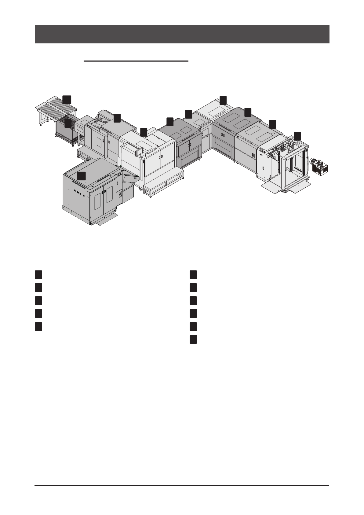
Features of the Machine
1-1-1
SmartStacker Configuration
Here are the sections included in a typical production line, along with the abbreviations we will use in this
manual.
1 Sheet Feeder (SF) (Option)
2 1st Regist Unit (1Reg)
3 1st Process Unit (1Pro)
4 90-degree Turn Conveyor (TC)
5 2nd Regist Unit (2Reg)
6 2nd Process Unit (2Pro)
7 Merge Conveyor (MC)
8 Merge Stacker (MS)
9 Output Shift Conveyor
10
1m Conveyor
11
B2 Stacker (BS)
14 SmartStacker User's Manual
Page 15
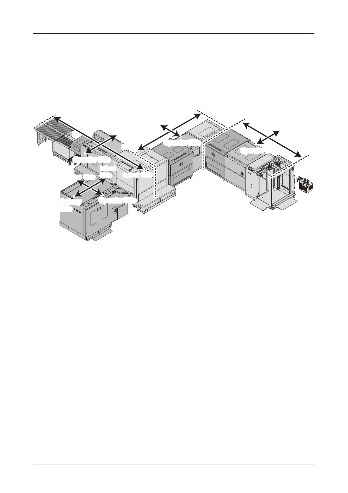
Features of the Machine
1-1-2
Delivery Side
Delivery
Side
Directions described in this manual
Infeed Side
Drive Side
Drive Side
Delivery
Operator Side
Operator Side
Drive Side
Delivery
Side
Side
Infeed
Infeed Side
Side
Operator SideOperator Side
Infeed Side
Operator SideOperator Side
Delivery Side
Operator Side
Operator Side
Drive Side
Infeed
Side
15SmartStacker User's Manual
Page 16
Features of the Machine
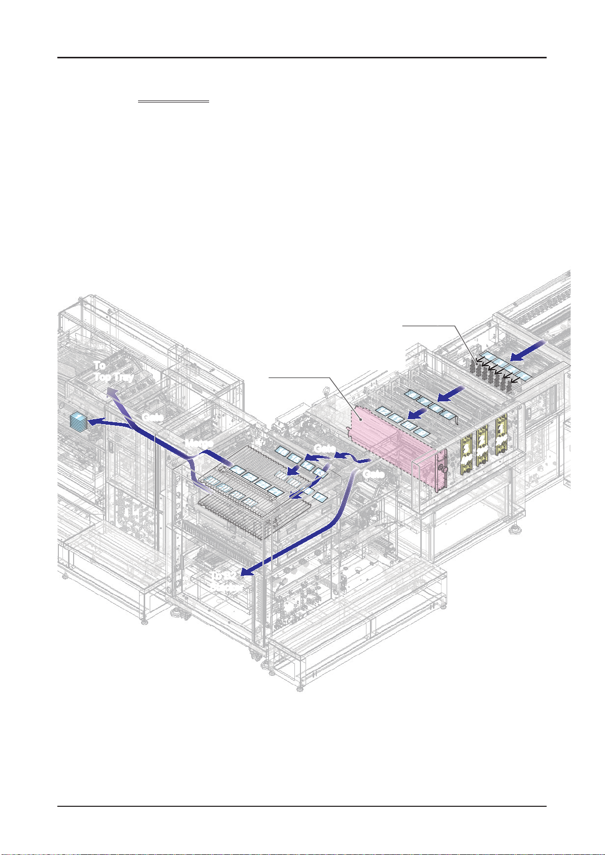
1-1-3
To
To
Top Tray
Top Tray
11
Sheet Flow
GateGate
MergeMerge
24 23 22 2124 23 22 21
28 27 26 2528 27 26 25
Scoring Unit
(Optional)
16 15 14 1316 15 14 13
20 19 18 1720 19 18 17
Gate
Gate
2nd Process
(9 Cutters)
12 11 10 912 11 10 9
Gate
Gate
2nd Regist
8 7 6 58 7 6 5
33
4pc4pc
4 3 2 1
4 3 2 1
11
22
2pc2pc
3pc3pc
To B2
To B2
Stacker
Stacker
16 SmartStacker User's Manual
Page 17
16 15 14 13
16 15 14 13
20 19 18 17
20 19 18 17
24 23 22 21
24 23 22 21
28 27 26 25
28 27 26 25
4 3 2 14 3 2 1
8 7 6 5
8 7 6 5
12 11 10 9
12 11 10 9
4pc4pc
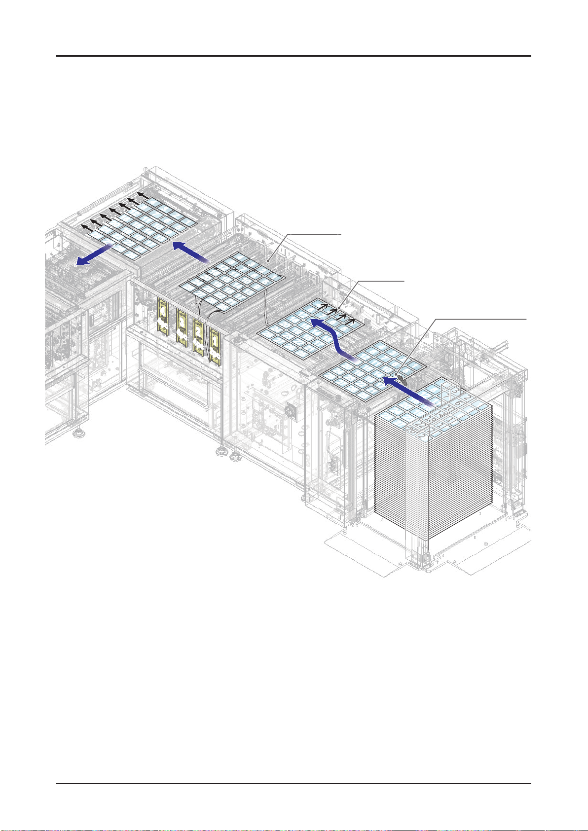
Features of the Machine
1st Process
(14 Cutters)
4
4
8
8
3
15
15
18
18
21
21
11
11
14
14
17
17
3
7
7
2
2
6
6
1
10
10
13
13
1
5
5
9
9
4
4
8
8
3
28
28
24
24
27
27
20
20
23
23
26
26
16
16
19
19
22
22
25
25
12
12
15
15
18
18
21
21
11
11
14
14
17
17
3
7
7
10
10
13
13
28
28
6
6
9
9
24
24
27
27
2
2
1
1
5
5
16
16
20
20
19
19
23
23
26
26
1st Regist
4
4
8
8
12
12
7
7
11
11
15
15
10
10
14
14
18
18
13
13
22
22
17
17
21
21
25
25
28
28
3
3
6
6
24
24
9
9
27
27
2
2
20
20
5
5
23
23
26
26
Double Feed Detect
Ultrasonic Sensor
1
1
4
4
8
8
3
15
15
18
18
21
21
11
11
14
14
17
17
7
7
10
10
13
13
3
2
2
6
6
9
9
16
16
19
19
22
22
12
12
25
25
1
1
5
5
12
12
16
16
20
20
24
24
19
19
28
28
23
23
27
27
22
22
26
26
25
44
25
33
22
4pc
4pc
4pc4pc
11
2pc2pc
17SmartStacker User's Manual
Page 18
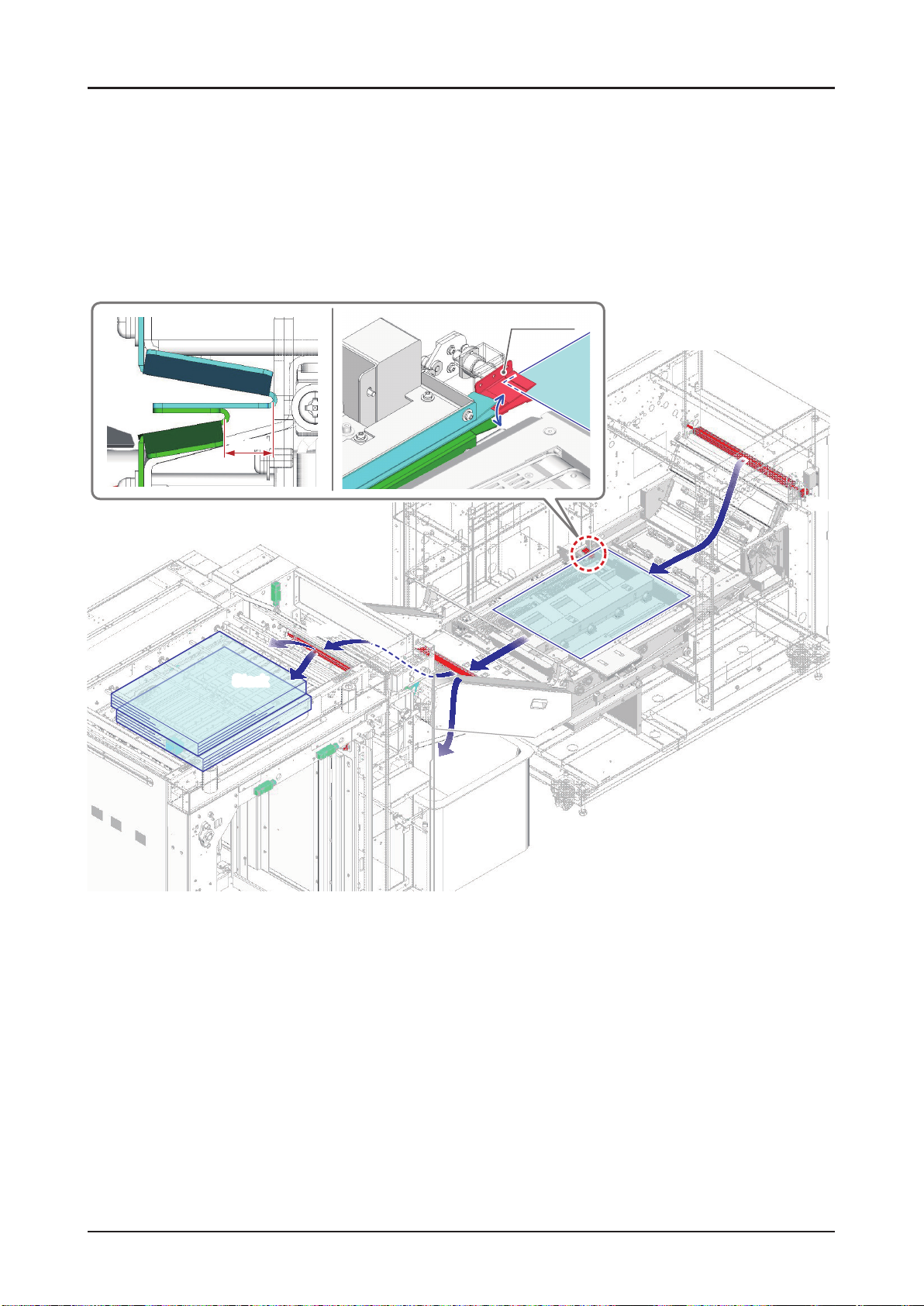
Features of the Machine
10 mm
Offset Guide
GateGate
Stack
Stack
Gate
Gate
Gate
Gate
Eject
Eject
26030
10103C1
18 SmartStacker User's Manual
Page 19
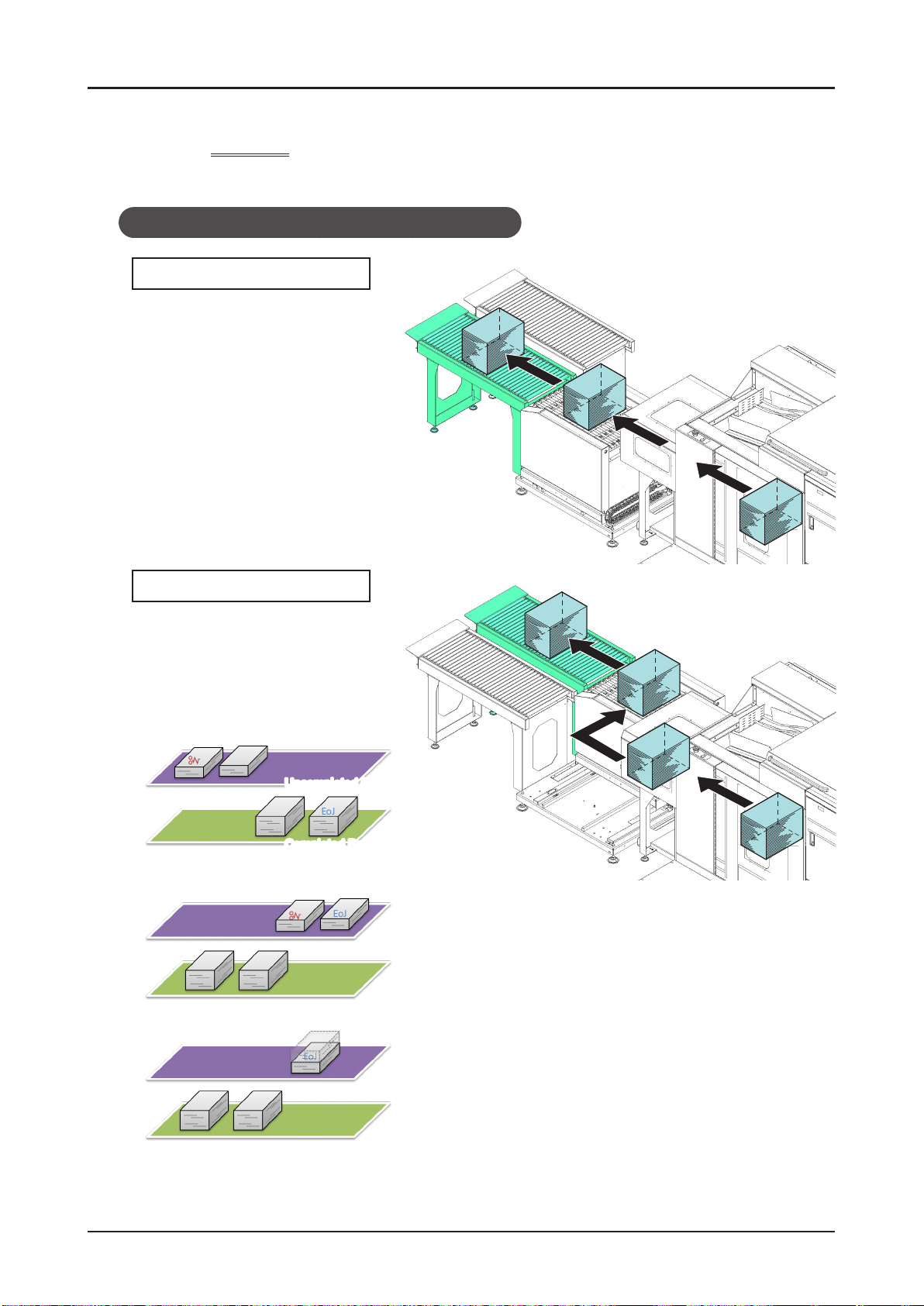
Features of the Machine
1-1-4
The processed stacks will be delivered to either of two destinations.
Delivery
When Using in the Near Line or Inline System
To Completed Conveyor
The stack goes to the complete
conveyor in case that the stack is
reached to the planned number of
sheets.
To Uncompleted Conveyor
A stack which is less than the
planned number of sheets goes to the
uncompleted box in all cases.
For Example of 3 stacks in job
• A jam on middle of the rst stack
Uncompleted Box
Completed Box
(Eoj = End of Job)
• A jam on middle of the last stack
• The job end on middle of the last stack
19SmartStacker User's Manual
Page 20

Features of the Machine
• The job end on middle of the rst stack
• If the “Offset” or “None” is selected for the operations after job processing on the FLC screen, the
previous job is not delivered, and the Line Clear button is pressed
• The user changes starting sheet number (from the Press UI)
• The user changes starting sheet number after the jam
Uncompleted Box
Completed Box
• Break of a job with changeover
20 SmartStacker User's Manual
Page 21

Features of the Machine
When using in the ofine system
To Completed Conveyor
The stack goes to the completed conveyor in case that the stack reaches the planned number of
sheets.
The block whose number of sheets reaches the planned number goes to the completed conveyor.
To Uncompleted Conveyor
A stack which is less than the planned number of sheets goes to the uncompleted box in all cases.
• The jam occurs at rst block of the second stack when the job is set in 3 stacks.
Fist Block
Uncompleted Box
Completed Box
Second and After Block
21SmartStacker User's Manual
Page 22
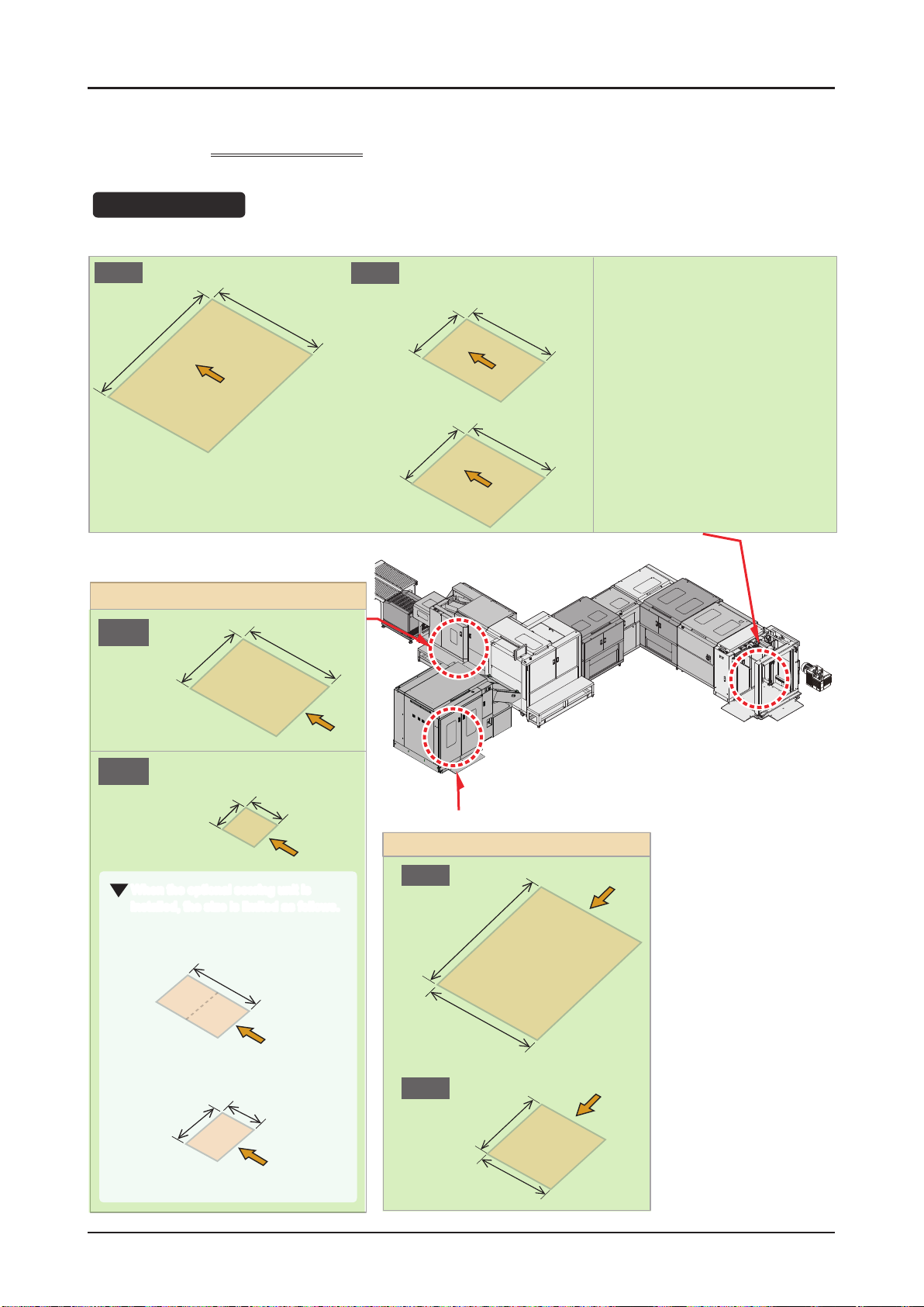
Features of the Machine
1-1-5
Sheet Size
Uncut Size
Max.
762 mm
30.000”
Finished Size
Supported Jobs
530 mm
20.865”
Min.
When delivered to Merge Stacker
279.4 mm
11.000”
When delivered to B2 Stacker
380mm
14.965”
330 mm
12.995”
330mm
12.995”
Standard Size
ISO A Series: A2 / A3
ISO B Series: B2 / B3
Inch Series: 18” x 24” / 17” x 22” /
13” x 19”
Merge Stacker
Max.
381 mm
15.000”
Min.
100 mm
3.940”
When the optional scoring unit is
installed, the size is limited as follows.
With Scoring
Without Scoring
148 mm
5.83”
177.8
7”
through
(Min.)
105 mm
4.13”
530 mm
20.865”
105 mm 4.135”
through
265 mm
10.43”
Finished Size
B2 Stacker
Max.
762 mm
30.000”
530mm
20.865”
Min.
380 mm
14.965”
210 mm
8.270”
22 SmartStacker User's Manual
Page 23
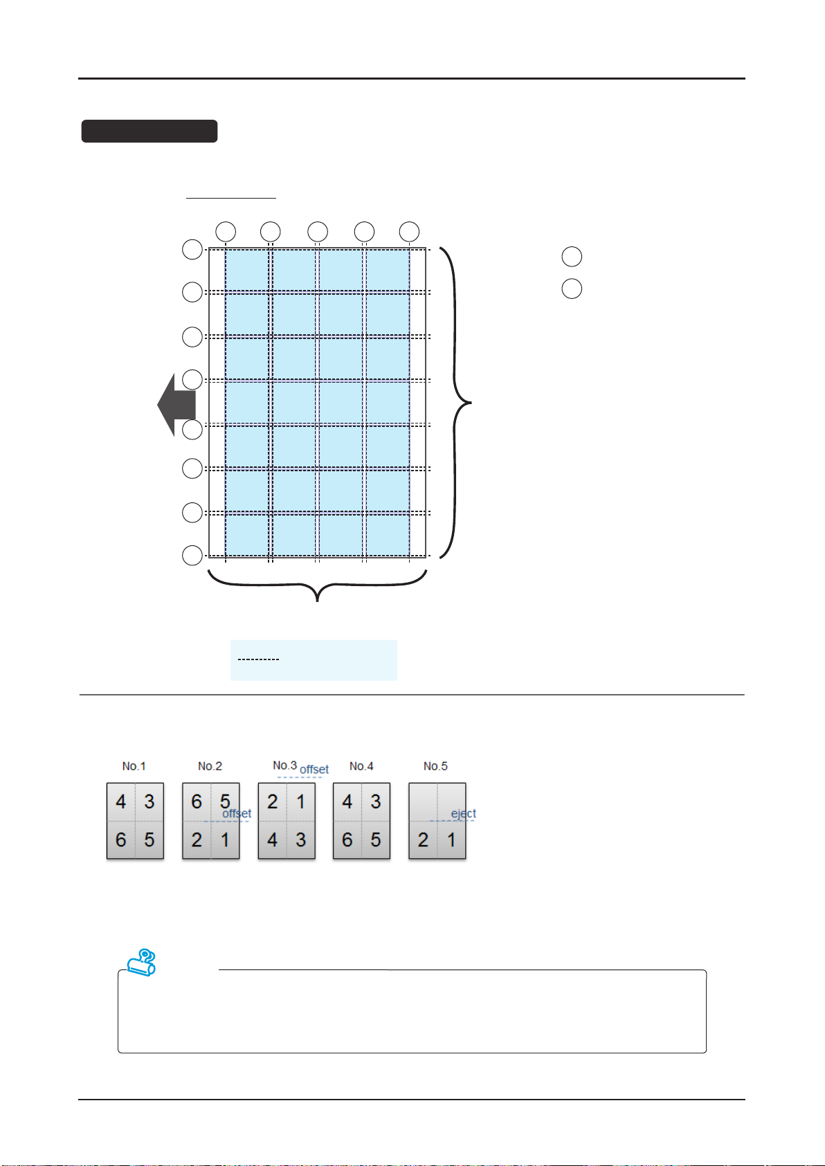
Number of Cuts
28-up (Max)
Features of the Machine
Feed
Direction
E
G
G
G
G
G
G
E
G G G
1234
5678
9101112
13141516
17181920
21222324
25262728
1 to 4 rows (8 cutters)
E E
: Edge Trim
E
(Bleed Trim)
: Gutter Trim
G
1 to 7 columns (14 cutters)
Slit Positions
Several blocks can be included in a job.
(The system can feed sheets with different numbers of pages.)
Attention
The maximum number of sheets which is capable in one job is as following:
• For near line operation: 100,000 sheets
• For inline operation: 50,000 sheets
23SmartStacker User's Manual
Page 24
Features of the Machine
Limitations of offset and delivery
The offset function and delivery function can be set in parallel to the feeding direction. They cannot
be set in perpendicular.
OK NG
The ejection operation can be done after the last row and other one row.
No.1
23
45
OK NG
No.2
45
offset
1
eject
123
4567
eject
123
4567
No.1
123
123
No.2
23
45
eject
eject
1234
eject
34
51
offset
The ejecting operation
cannot be done twice
except after the last row.
4567
24 SmartStacker User's Manual
Page 25
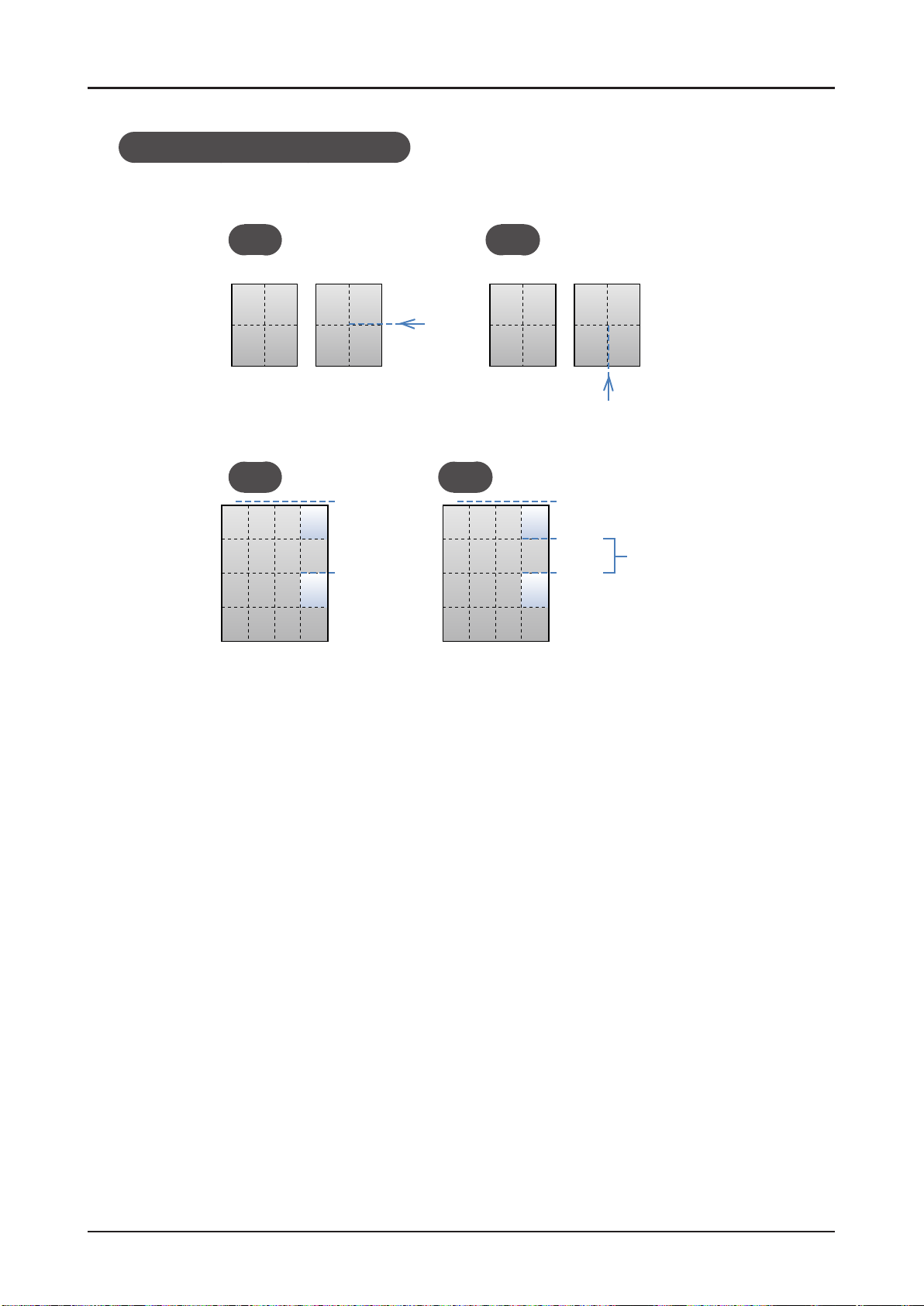
Limitation for blank page removal
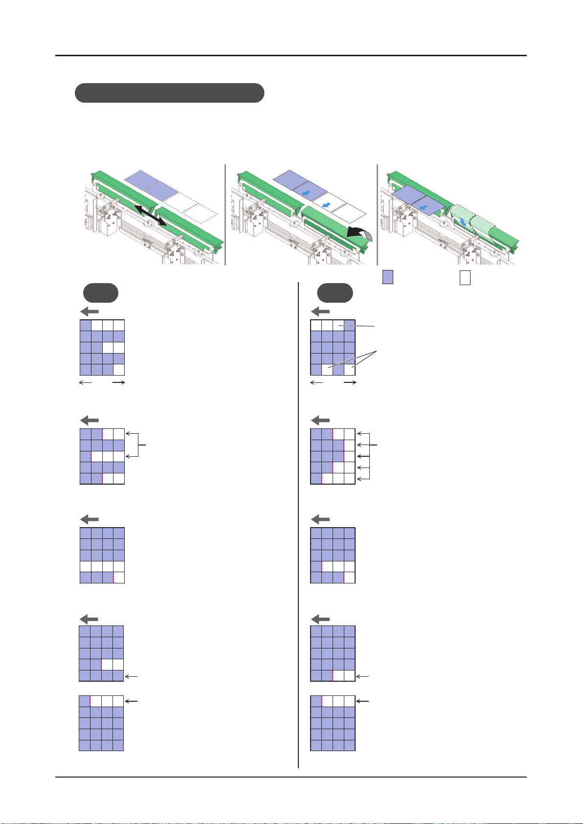
Mechanism of Blank Page Removal
Features of the Machine
1. The gates slide to the
2. The gates open. 3. The blank pages which are
position where the blank
pages will pass.
OK NG
Feed direction Feed direction
The blank pages must be arranged
from the tail edge along the feeding
direction so that the several pages
can be removed at once.
Leading
edge
Tail
edge
Leading
edge
hit against the gates will be
ejected.
Printed page Blank page
The blank pages are arranged in the
leading edge.
The blank pages are not continued from the tail edge.
Tail
edge
Feed direction Feed direction
If there are at least one row
between the blank pages as this
drawing, the blank page can be
ejected.
Feed direction Feed direction
However, in case that the blank pages are continued against the feeding
direction of the 2nd process unit, if
all the pages on the next row is blank
pages, the removal is possible.
Feed direction Feed direction
If there are at least one row
between the blank pages as
this drawing, the blank page
can be ejected.
Next sheet
Next sheet
First
row
Last
row
In case that several rows which
have different separation position
are continued, the SmartStacker
cannot eject the blank pages.
In case of this drawing, the SmartStacker cannot eject the blank
pages. Because two rows which
have different separation position
are continued.
In case of this drawing, the
SmartStacker cannot eject
the blank pages. Because
First
row
Last
row
two rows which have different separation position are
continued.
Next sheet
Next sheet
25SmartStacker User's Manual
Page 26

Features of the Machine
1-1-6
Functions Ofine Near line Inline
Sheet Cut and Stack Enable Enable Enable
Create a Job Enable Disable Disable
Fine Adjustment of
the Job Setting
JDF-based Operation Disable Enable Enable
Blank Page Rejection Disable Enable Enable
Operation Using the
Banner Sheet
Continuous Operation
of Multiple Jobs
Reprint Process
after an Error
Progress Report to the
Upstream System
Capability of Each Line
Enable
Disable Enable Enable
Disable
Disable
Disable Disable Enable
Enable
but ag is
necessary to set
Enable
using banner sheet
Enable
(You print the reprint
list and pass it to an
operator for press.)
Enable
but the ne-
adjustment should
be made before
printing is started
Enable
Enable
• Ofine and Near line can be switched just by pressing a button, but to use as the Inline system, the machine
should be installed again.
26 SmartStacker User's Manual
Page 27
Features of the Machine
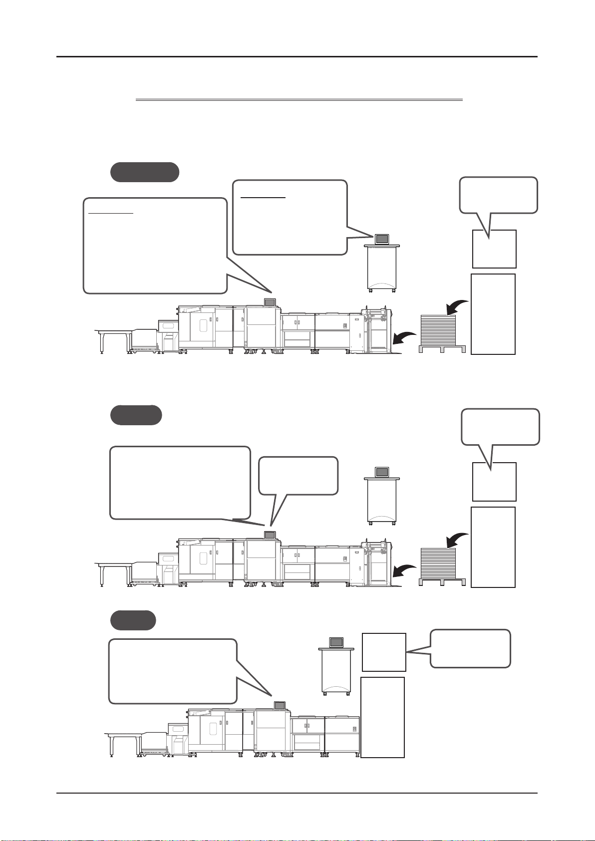
1-1-7
The Role of Panels of the SmartStacker and the FLC
The role of panels of the SmartStacker and the FLC, the procedure to create and start a job, and also to
make the ne adjustment are different depending on the conguration of line. The outline is shown below.
Near Line
Main Role
Saving the ne adjustment
•
values to the memory
beforehand
Recalling the saved adjustment
•
before running the job that was
set the ag
Main Role
Starting the job
•
Setting the ag on the
•
job
Creating the reprint list
•
Panel
FLC
FeederSmartStacker
Pallet
Creating the job
DFE
(UBM)
Press
Ofine
Saving the ne adjustment
•
values to the memory
beforehand
Recalling the saved job setting
•
Inline
Enter the values for the ne
•
adjustment before starting
the operation so that the
ne adjustment values are
carried over.
Panel
Panel
Creating the job
•
Starting the job
•
FLC
FeederSmartStacker
FLC
DFE
(UBM)
Press
Pallet
Creating the job
•
Starting the job
•
Creating and starting
the job for print
DFE
(UBM)
Press
SmartStacker
27SmartStacker User's Manual
Page 28
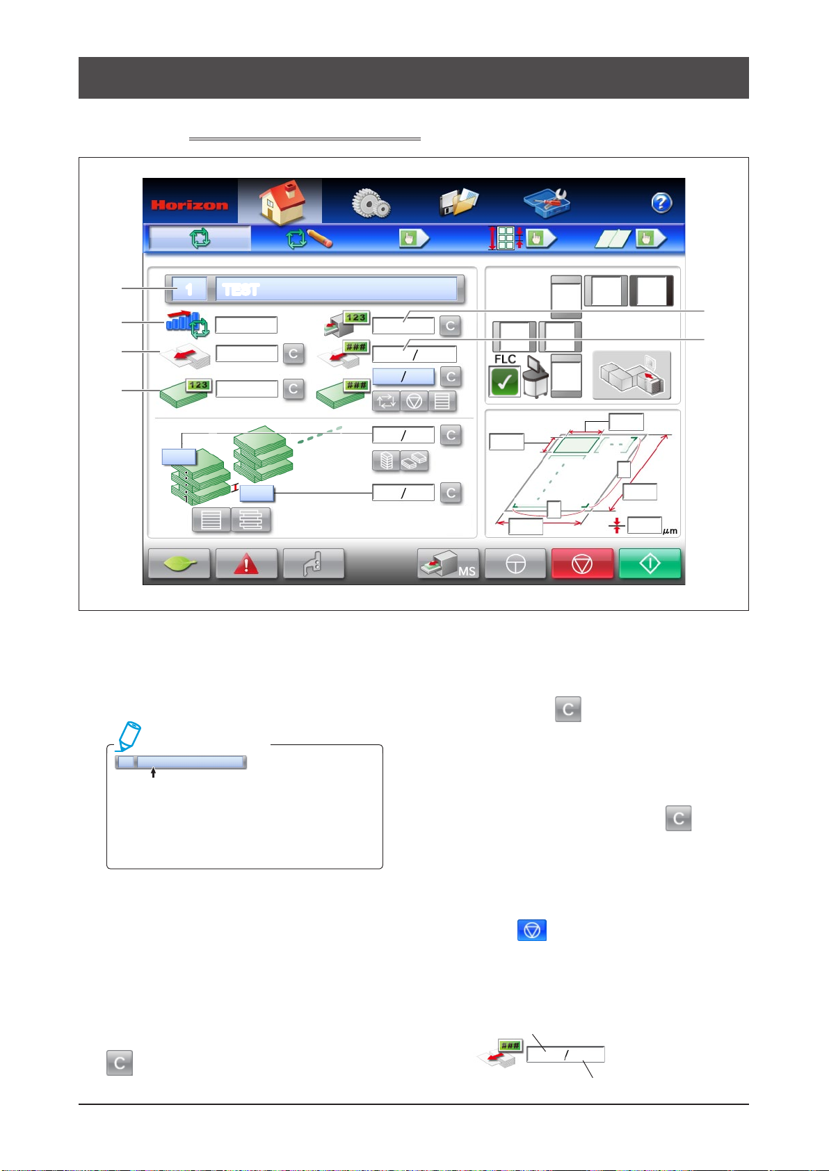
1-2
SmartStacker Screen Descriptions
1-2-1
1
2
3
4
Run - Main Screen - Part 1
1 TEST
5
pieces/hr
6
Job Name
1
When you recall a job from the job memory in the
ofine system, the current job number and name are
displayed here.
Additional Information
1 TEST
If you change the settings or ne adjustment
settings after recalling the job from the memory
screen, the name of the job shown in the draw-
ing above will change to red. Save the modied
job with a different name if necessary.
Production Speed Indicator
2
The current operation speed (number of pages per
hour) is shown here.
Feed Counter for Uncut Sheets
3
The total number of fed uncut sheets is displayed
here. This number is saved even if the power is
turned off. If you are using this machine in the
ofine mode and want to change the job, press
(Clear) to reset the counter to zero.
Delivered Block Counter
4
This shows the number of blocks that have been
delivered. The number is saved even if the power is
turned off. Press
zero.
Counter for Delivered Pages (Pieces)
5
The total number of delivered pages is displayed
here. Every piece is counted. The number is saved
even if the power is turned off. Press
reset the counter to zero.
Preset Counter for the Number of Uncut
6
Sheets
If you are using the machine in the ofine mode, and
you press
sheets is displayed. The number of uncut sheets
which should be fed is calculated automatically using
the counter for the number of pages in each block
and the preset counter for the total number of blocks.
Number of sheets already fed
(Clear) to reset the counter to
(Stop), the preset number of uncut
0
10
Total number of sheets to be fed
(Clear) to
28 SmartStacker User's Manual
Page 29
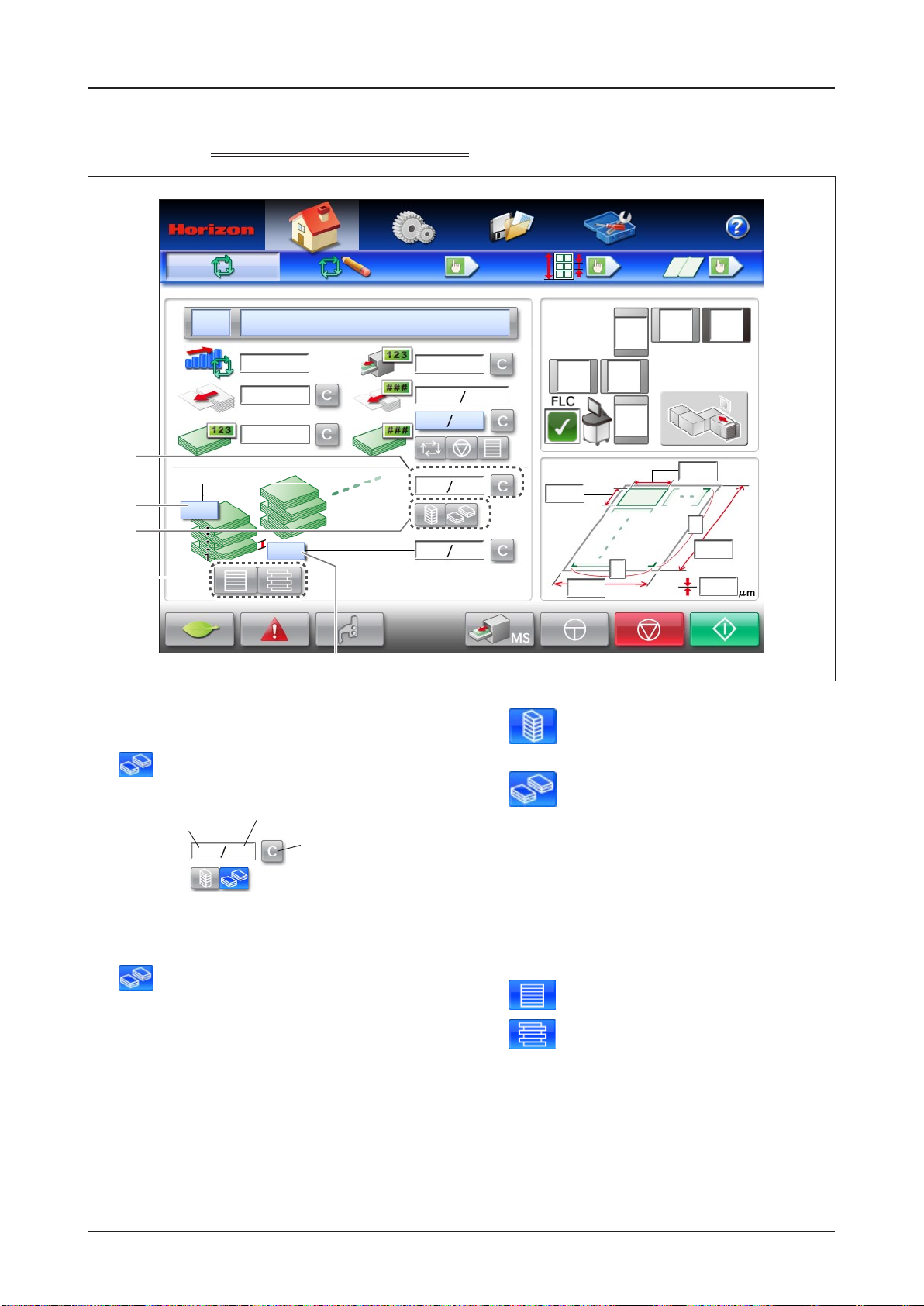
SmartStacker Screen Descriptions
1-2-2
1
2
3
4
Run - Main Screen - Part 2
pieces/hr
5
Counter for the Number of Blocks in Each Stack
1
When the machine is used in an ofine system and
is selected for the stack function, the number
of blocks stacked is displayed.
Number of blocks
already stacked
Number of Blocks in Each Stack
2
When the machine is used in an ofine system and
is selected for the stack function, enter the
number of blocks in each stack.
Stack Function On/Off
3
Use this to set how many blocks should be stacked in the
stacker before the blocks are delivered.
If you are using the machine in an inline system
or a near line system, the setting on the press is
displayed and this function cannot be set from this
screen. If you are using the machine in the ofine
mode, set this function on this screen.
Number of blocks in each stack
0 5
Press this button to
clear the number of
blocks which have
already been stacked.
This turns off the stack function. The machine will
continue feeding the uncut sheets until the pages
reach the upper limit of the Merge Stacker.
This turns on the stack function. The
machine will stop after feeding the number
of blocks in one stack.
Offset Function On/Off
4
Use this setting to set whether or not each block is
offset by the stacker.
If you are using the machine in an inline system or a near
line system, the setting on the press is displayed and this
function cannot be set from this screen. If you are using the
machine in the ofine mode, set this function on this screen.
The offset function is turned off (straight stacking).
All of the blocks of pages are stacked without any offset.
The offset function is turned on.
One block is offset to the right, and the next
block is offset to the left.
Number of Sheets for One Block
5
Enter the number of sheets for one block.
If you are using the machine in an inline system or a
near line system, the setting on the press is displayed
and this function cannot be set from this screen. If
you are using the machine in the ofine mode, set this
function on this screen.
29SmartStacker User's Manual
Page 30
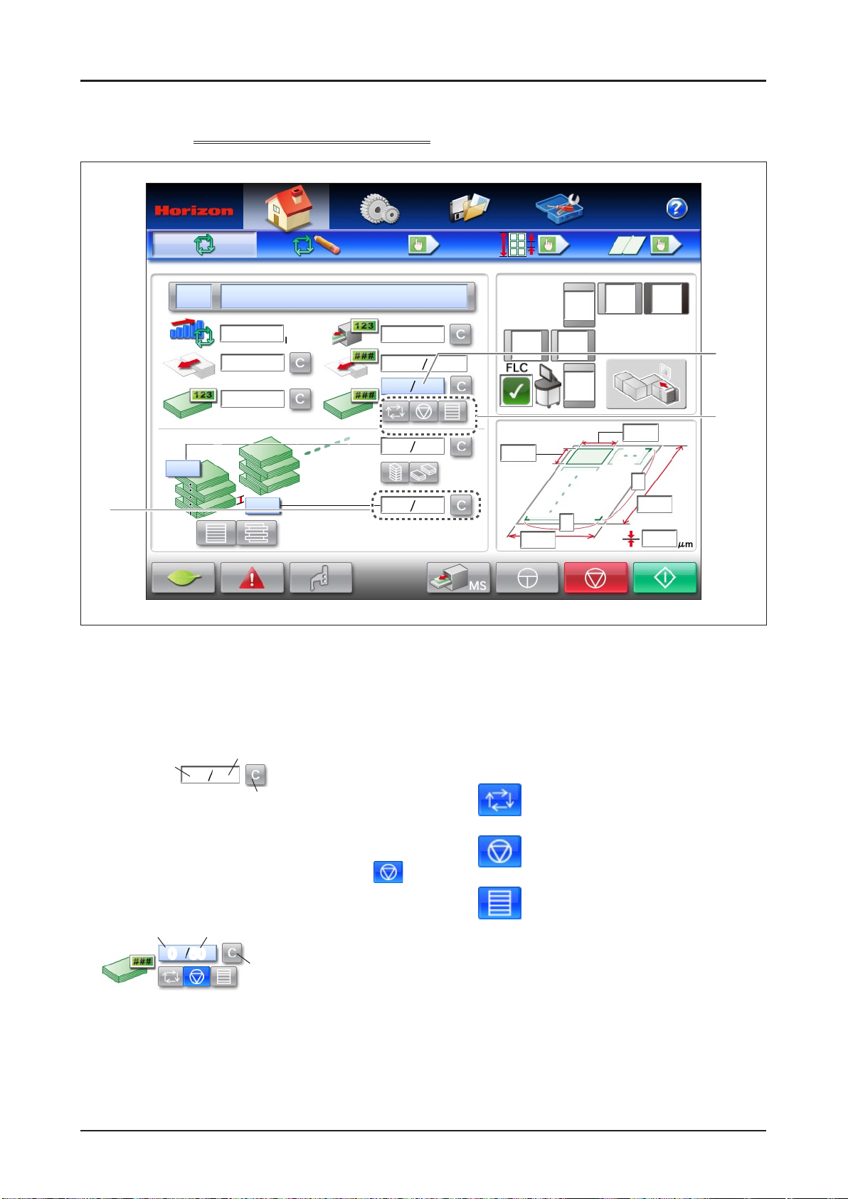
SmartStacker Screen Descriptions
1-2-3
1
Run - Main Screen - Part 3
pieces/hr
2
3
Counter for the Number of Pages
1
(Pieces) in Each Block
This indicates the number of pages included in one
block, and the number of pages already stacked.
Number of pages
already stacked
0 5
Press this button to clear the number of
pages which have already been stacked.
Preset Counter for the Total Number of Blocks
2
If you are using the machine in the ofine mode and select
(stop) for the preset function, enter the preset number of blocks.
Number of blocks
already delivered
0 50
Number of pages included
in one block
Total preset number of blocks
Press this button to clear the
number of blocks which have
already been delivered.
Total Preset Function On/Off
3
Use this setting to set how many blocks should be
delivered before the machine stops. If you are using the
machine in an inline system or a near line system, the
setting on the press is displayed and this function cannot
be set from this screen. If you are using the machine in the
ofine mode, set this function on this screen.
The preset function is turned off. The machine
continues feeding the uncut sheets until the
Stop button is pressed or the sheets run out.
The preset function is turned on. The machine
stops after feeding the number of blocks which
has been set on the preset counter.
All of the blocks are stacked without offsetting.
When the top of the stack reaches to the
upper limit of the Merge Stacker, the sets are
delivered.
30 SmartStacker User's Manual
Page 31

SmartStacker Screen Descriptions
1-2-4
Run - Main Screen - Part 4
pieces/hr
1
2P
SF1P
2
3
MCMS
4
5
6
7
Help Button
1
Press this button to see explanations of each of the
icons on the screen.
Status Icon
2
Status icons are displayed for each machine.
Running
Interlock Circuit Open
(This icon means that the
Emergency Stop button has been
pressed or the safety cover has
been opened.)
Not Ready (An error occurred
during the changeover and the
machine is stopped.)
No Icon: Stopping
Internal Network Communication Error Icon
3
The icon is displayed if there is a problem with the
network communications.
The communication network has a
problem.
The machine is checking if the
communication device exists.
External Network Communication Error Icon
4
The icon is displayed if there is a problem with the
network communication between the systems.
Line System Icon
5
These icons show how the unit will operate with the
rest of the production line.
Ofine
Near line
Inline
Status of FLC and Line System
6
This icon is displayed when the FLC is connected
with an Inline system or with a Near Line system.
See page 83 for details of icon.
Sheet Size
7
This indicates the current sheet size and thickness.
31SmartStacker User's Manual
Page 32

SmartStacker Screen Descriptions
1-2-5
Run - Main Screen - Part 5 (for Merge Stacker)
2P
pieces/hr
MCMS
1
Power Saving Mode
1
When this button is pressed, the machine goes into
power saving mode. The display on the touch panel
disappears. When you touch the panel again, the
machine returns to the normal mode.
Go to the Error Screen
2
Press this button to display the Error screen. See
page 78 for details.
Trim Guide Setting Screen Display
3
2
Button
Press this button to display the Trim Guide Setting
screen. Use this button to check wether the trim
guide is set for the current job. See page 50 for
details.
Block Delivery Button
4
Press this button to deliver the block from the Merge
Stacker. Use this button after an error occurs and
the machine stops.
Jog Button
5
Press and hold this button to move the sheets
forward. Use this button after an error occurs and
the machine stops.
4
Stop Button
6
If the machine is used in an ofine system or a
near line system, press this button to stop feeding.
Any sheets which are in-process are nished and
delivered, and the machine is stopped.
`Immediately` is selected for the Stop Timing).
When the machine is used in a Near Line system,
the timing to stop the machine can be changed.
See page 81 for details.
Start Button
7
This button is used if the machine is used in an ofine
system or a near line system.
If the machine is used in an ofine system, press this
button to start the feeding and cutting operations.
If the machine is used in a near line system, press
this button to do the changeover, the feeding and
cutting operation following the information of read
barcode. If the job does not have a barcode, the
system runs following the information of the Pending
job that is selected on the screen of FLC.
5
Attention
6
73
(when
32 SmartStacker User's Manual
Page 33

SmartStacker Screen Descriptions
1-2-6
See
page 28.
See
page 29.
Run - Main Screen - Part 6 (for B2 Stacker)
pieces/hr
See
page 31.
See
page 30.
See page 32.
33SmartStacker User's Manual
Page 34

SmartStacker Screen Descriptions
1-2-7
1
2
3
Run - Setting Screen - Part 1
Feed Speed
1
This sets the number of uncut sheets to be
processed per hour.
Feed Rotor Suction Length
2
This sets the suction length of the feed rotor. If the
machine misfeeds, make the length longer. If the
machine double-feeds, make the length shorter.
Amount of Downward Vacuum of the
3
Transport Roller Section
T
his sets the amount of vacuum provided by the fans below the
transport rollers in the Merge Conveyor.
Increase the vacuum air if the sheets do not align with the angle
adjusting guide and result in misaligned stack of sheets.
Adjust the air if the sheets do not run on the transport rollers
smoothly and result in an error, the error code 340 / 350; Sheet
has not arrived at upper / lower transport section sheet pass
sensor, or the error code 341 / 351; Sheet remains at upper /
lower transport section sheet pass sensor.
(Reduce the air for light sheets such as normal paper.
Increase the air for heavy sheets such as coated paper.)
Angle Adjusting Guide
Fans
34 SmartStacker User's Manual
Page 35

SmartStacker Screen Descriptions
1-2-8
Run - Setting Screen - Part 2 (for Merge Stacker)
1
2
3
4
Supporting Air
1
When the vacuum belts are transporting a sheet
to the top of the stack in the Merge Stacker, air is
supplied to support sheet. The amount of air can be
adjusted here.
Use the smallest amount of air that will provide
reliable operation. If you are running thin or soft
sheets, and they are bent and do not stack correctly,
increase the amount of air.
Amount of Upward Vacuum of the
2
Vacuum Belt
This sets the amount of vacuum provided by the
vacuum belt in the Merge Stacker.
Usually this should be set to maximum.
If you are running thin sheets which do not separate
from the belt when they reach the stopper, reduce
the vacuum.
Jogging Motion On/Off
3
This turns the jogging motion in the Merge Stacker
on or off.
This is the standard setting. The stopper
will jog every sheet.
The stopper will not jog the sheets.
Bypass for the Merge Stacker
4
This turns the jogging motion in the Merge Stacker
on or off.
Sheets are stacked on the merge stacker.
Normally, select this button.
This button is currently not available.
35SmartStacker User's Manual
Page 36

SmartStacker Screen Descriptions
1-2-9
3
Run - Setting Screen - Part 3 (for B2 Stacker)
1
2
Supporting Air
1
When the vacuum belts are transporting a sheet to
the top of the stack in the B2 Stacker, air is supplied
to support sheet. The amount of air can be adjusted
here.
Usually this should be set to maximum. Use
the large amount of air that will provide reliable
operation. If you are running thin or soft sheets, and
they are bent and do not stack correctly, increase
the amount of air.
Adjustment of Upward Vacuum of the
2
Vacuum Belt
This sets the amount of vacuum provided by the
vacuum belt in the B2 Stacker.
If the sheet does not reach the stopper in the stack
section, press
vacuum. If you are running thin sheets which do not
separate from the belt when they reach the stopper,
or if a jam occurs, reduce the vacuum.
to increase the amount of
Amount of Downward Vacuum of the
3
Register Guide Section
This sets the amount of vacuum provided by the fans
below the register section in the Merge Conveyor. Increase
the vacuum air if the sheets do not align with the register
guide and result in misaligned stack of sheets.
If a jam caused by hitting the register guide (any scratches or
transport error caused by sheet bent) occurs, press
reduce the vacuum.
Register Guide
Register Section
You can see the sheet ow from above the sheet receiving
section of the Merge Conveyor and the B2 Stacker. Check that
the sheet is aligned to the guide.
to
36 SmartStacker User's Manual
Page 37

SmartStacker Screen Descriptions
1-2-10
Run - Setting Screen - Part 4 (for B2 Stacker)
1
Bypass for the B2 Stacker
1
This turns the jogging motion in the B2 Stacker on or
off.
Sheets are stacked on the B2 stacker.
Normally, select this button.
This button is currently not available.
37SmartStacker User's Manual
Page 38

SmartStacker Screen Descriptions
1-2-11
The sheet feeder is optional.
Run - Fine Adjustment Screen - Part 1
3
4
5
1
2
Option
6
7
Sheet Feeder Table Guide Position
1
The table guide position can be adjusted here. The
tail edges of the sheets are registered by this guide
when they are loaded into the table.
Sheet Feeder Suction Head Position
2
The suction head position can be adjusted here.
Position the suction head so that the set register pin
of the suction head ts against the tail edge of the
stack of sheets.
Sheet Feeder Rear Guide Position
3
The rear guide position can be adjusted here.
1st Regist Unit Register Guide Position
4
The register guide position can be adjusted here.
The sheets move to the rear and are positioned by
this guide.
2nd Process Unit Gate Position
5
The blank page ejecting gate position can be
adjusted here. When the pages are delivered to the
waste tray, if the edges hit the gate and jam, adjust
the position of the gate.
Merge Conveyor Upper Stopper and
6
Angle Adjusting Guide Position
The upper stopper and angle adjusting guide
position can be adjusted here.
After the sheets were delivered onto the transport
roller section and turned the direction, they are
aligned with the angle adjusting guide while they are
transported through between the stopper and the
angle adjusting guide.
Adjust the guide if the sheets from upper section and
the sheets from lower section of Merge Conveyor are
regularly misaligned in a stack.
Merge Conveyor Lower Stopper and
7
Angle Adjusting Guide Position
The lower stopper and angle adjusting guide position
can be adjusted here.
After the sheets were delivered onto the transport
roller section and turned the direction, they are
aligned with the angle adjusting guide while they are
transported through between the stopper and the
angle adjusting guide.
Adjust the guide if the sheets from upper section and
the sheets from lower section of Merge Conveyor are
regularly misaligned in a stack.
38 SmartStacker User's Manual
Page 39

SmartStacker Screen Descriptions
1-2-12
The sheet feeder is optional.
Run - Fine Adjustment Screen - Part 2
1
2
Option
Merge Stacker Stopper Position
1
The stopper position can be adjusted here. The
head of the stack is held by this stopper while the
pages are stacked.
Merge Stacker Sheet Holding Plates
2
Pressure
The sheet holding plates prevent the sheets from
bouncing back from the stopper.
This pressure is automatically adjusted according to
the thickness of sheet. (The pressure is reduced for
thin sheets, and increased for thick sheets.) If you
want to change the pressure, make the adjustment
here.
If a sheet does not reach the stopper and causes a
jam, decrease the pressure.
If the front and rear edges of the stack are not
aligned correctly, increase the pressure.
39SmartStacker User's Manual
Page 40

SmartStacker Screen Descriptions
1-2-13
The sheet feeder is optional.
Run - Fine Adjustment Screen - Part 3 (for B2 Stacker)
Option
Option
B2 Stacker Stopper Position
1
The stopper position can be adjusted here. The
head of the stack is held by this stopper while the
pages are stacked.
B2 Stacker Sheet Separate Plates Pressure
2
The sheet separate plates prevent the sheets from
bouncing back from the stopper.
This pressure is automatically adjusted according to
the thickness of sheet. (The pressure is reduced for
thin sheets, and increased for thick sheets.) If you
want to change the pressure, make the adjustment
here.
If a sheet does not reach the stopper and causes
a jam, decrease the pressure. If the front and
rear edges of the stack are not aligned correctly,
increase the pressure.
1 2
40 SmartStacker User's Manual
Page 41

SmartStacker Screen Descriptions
1-2-14
1
2
3
4
Run - Page Size Fine Adjustment Screen - Part 1 (for Merge Stacker)
5
Page Length
1
The page length can be adjusted. If the cut sheets
are longer or shorter equally than the desired
dimension, adjust the page length setting here.
Value Before Fine Adjustment
V alue After Fine Adjustment
Bleed Trim Length
2
If the bleed and gutter trim position of all of the
pages is shifted to the right or left, adjust the length
here.
Bleed Trim Width
3
If the bleed and gutter trim position of all of the pages
is shifted up or down, adjust the width here.
Feed
Direction
Page Width
4
The page width can be adjusted. If the width of all of
the pages is too wide or too narrow, adjust the width
here.
Feed
Direction
Go to the 1st Process Unit Fine
5
Adjustment Screen
41SmartStacker User's Manual
Page 42

SmartStacker Screen Descriptions
1-2-15
1
2
3
4
Run - Page Size Fine Adjustment Screen - Part 2 (for B2 Stacker)
5
Page Length
1
The page length can be adjusted. If the cut sheets
are longer or shorter equally than the desired
dimension, adjust the page length setting here.
Value Before Fine Adjustment
V alue After Fine Adjustment
Bleed Trim Length
2
If the bleed trim position is shifted to the right or left,
adjust the length here.
Bleed Trim Width
3
If the bleed trim position is shifted up or down, adjust
the width here.
Feed
Direction
Page Width
4
The page width can be adjusted. If the width of all of
the pages is too wide or too narrow, adjust the width
here.
Feed
Go to the 1st Process Unit Fine
Direction
5
Adjustment Screen
42 SmartStacker User's Manual
Page 43

SmartStacker Screen Descriptions
1-2-16
1
2
Run - Cutter Position Fine Adjustment - 1st Process Unit Fine Adjustment Screen
3
5
Simultaneous Adjustment Button
1
Separately Adjustment:
The cutters are adjusted individually.
Simultaneous Adjustment:
When one of cutters is adjusted, all the
cutters in front than the adjusted cutter
are automatically adjusted along with the
adjusted cutter.
Cutter Position Fine Adjustment
2
If the one of bleed or gutter trim positions is shifted
up or down, adjust the position of the affected cutter.
Cutters which are not used for the selected job
cannot be adjusted.
Feed
Direction
Cutter Position Indication
3
This indicates which cutter positions are adjustable,
depending on the selected job.
Go to the 2nd Process Unit Fine
4
Adjustment Screen
Return to the Run - Page Size Fine
5
Adjustment Screen
4
43SmartStacker User's Manual
Page 44

SmartStacker Screen Descriptions
1-2-17
1
2
Run - Cutter Position Fine Adjustment - 2nd Process Unit Fine Adjustment Screen
3
5
Simultaneous Adjustment Button
1
Separately Adjustment:
The cutters are adjusted individually.
Simultaneous Adjustment:
When one of cutters is adjusted, all the
cutters in front than the adjusted cutter
are automatically adjusted along with the
adjusted cutter.
Cutter Position Fine Adjustment
2
If the one of the bleed or gutter trim position is
shifted to the right or left, adjust the position of the
affected cutter.
Cutters which are not used for the selected job
cannot be adjusted.
4
Cutter Position Indication
3
This indicates which cutter positions are adjustable,
depending on the selected job.
Go to the 1st Process Unit Fine
4
Adjustment Screen
Return to the Run - Page Size Fine
5
Adjustment Screen
Feed
Direction
44 SmartStacker User's Manual
Page 45

SmartStacker Screen Descriptions
1-2-18
1
Run - Scoring Position Fine Adjustment Screen (Optional)
2
Fine Adjustment of the Scoring
1
Position - Far Side
Each sheet is cut into two parts in the 2nd Process Unit.
If the scoring position is shifted from the desired position
on the far side of the page, adjust the position here.
Feed
Direction
Fine Adjustment of the Scoring Position
2
- Operator Side
Each sheet is cut into two parts in the 2nd Process Unit.
If the scoring position is shifted from the desired position
on the operator side of the page, adjust the position here.
Feed Direction
45SmartStacker User's Manual
Page 46

SmartStacker Screen Descriptions
1-2-19
8
7
6
5
4
3
Setting - Size Setting Screen - Only for Offline System- Part 1
1
2
Sheet Width
1
Enter the width of the sheet.
Allowable range for the sheet width:
279.4 to 762 mm / 11” to 30”
Division Number - Long Side
2
Enter the number of parts into which you want to
divide the long side of the sheet.
Allowable range for the division number - long side:
1 through 7
Sheet Length
3
Enter the length of the sheet.
Allowable range for the sheet length:
330 to 530 mm / 12.99” to 20.87”
Division Number - Short Side
4
Enter the number of parts into which you want to
divide the short side of the sheet.
Allowable range for the division number - short side:
1 through 4
Gutter Trim On/Off - Long Side
5
This is used to set whether to trim the gutter of the long side.
On: The gutter is trimmed
Off: No gutter trim
If you change this setting, the Trim Guides
Setting screen will be displayed when you do the
changeover. See page 50 for details.
Gutter Trim Width - Long Side
6
If you have turned on the gutter trim function, this is
used to set the gutter trim width.
Allowable range for the gutter trim width:
6 to 15 mm / 0.24” to 0.6”.
Page Width
7
Enter the page width.
Page Length
8
Enter the page length.
46 SmartStacker User's Manual
Page 47

SmartStacker Screen Descriptions
1-2-20
1
2
3
Setting - Size Setting Screen - Only for Offline System - Part 2
4
5
6
Long Edge Trim On/Off
1
This sets the trim function when the long edge of
sheet is cut.
Long Edge Trim Width (Register side)
2
When the long edge trim function is turned on, enter
the value of the long edge trim width on the register
side (rear side).
Long Edge Trim Width (Non-registered
3
side)
When the long edge trim function is turned on,
the value of the long edge trim width on the nonregistered side (front side) is displayed.
The value is decided according to the sheet size
(untrimmed sheet), nished sheet width, division
number, long edge trim width (register side).
If you enter a value which is out of range, the value
will be displayed in red.
On: Edge is trimmed.
Off: Edge is not trimmed.
Short Edge Trim On/Off
4
This sets the trim function when the short edge of
sheet is cut.
Short Edge Trim Width (Register side)
5
When the short edge trim function is turned on, enter
the value of the short edge trim width on the register
side (rear side).
Short Edge Trim Width (Non-registered
6
side)
When the short edge trim function is turned on,
the value of the short edge trim width on the nonregistered side (front side) is displayed.
The value is decided according to the sheet size
(untrimmed sheet), nished sheet length, division
number, short edge trim width (register side).
If you enter a value which is out of range, the value
will be displayed in red.
On: Edge is trimmed.
Off: Edge is not trimmed.
47SmartStacker User's Manual
Page 48

SmartStacker Screen Descriptions
1-2-21
Setting - Size Setting Screen - Only for Offline System - Part 3
1
2
3
4
5
Gutter Trim Width - Short Side
1
If you have turned on the gutter trim function, this is
used to set the gutter trim width.
Allowable range for the gutter trim width:
6 to 15 mm / 0.24” to 0.6”
Gutter Trim On/Off - Short Side
2
This is used to set whether to trim the gutter of the
short side. See the explanation for item number 5 on
the page 46.
Scoring On/Off (Option)
3
This can be set only if you plan to divide the short
side of the sheet into two parts. Once you turn on this
function, the positive score can be made on the center
of the sheet.
Sheet Thickness
4
Enter the thickness in µm of the sheet to be run.
This setting is used to adjust the how long to stack
table lowers in the Merge Stacker, to predict how
many pages can be stacked before the stacker is
full, and to determine the timing for delivery of the
pages.
6
Fine Adjustment Carry Over
5
Select this to carry over the ne
adjustment settings from the previous
job.
Use this for a new job, so the ne
adjustment values are cleared to zero.
Starting the Changeover After Home
6
Positioning
If this is selected, all of the parts of the machine
return to their home positions before the changeover
begins.
When the sheets on the feed table is raised to the
upper position and the changeover is started, the
buzzer sounds and the feed table is lowered for the
specied amount. After the changeover, the feed
table will be rising.
Starting the Changeover
7
If this is selected, the changeover starts immediately,
without the parts returning to their home positions.
When the sheets on the feed table is raised to the
upper position, the machine performs as same as
described above.
7
48 SmartStacker User's Manual
Page 49

SmartStacker Screen Descriptions
1-2-22
See page 47.
See page 46.
Setting - Size Setting Screen - Only for Offline System - Part 4 (for B2 Stacker)
See page 48.
49SmartStacker User's Manual
Page 50

SmartStacker Screen Descriptions
1-2-23
If you turn the gutter trim function On or Off, the Trim Guide Setting screen will be displayed when you
do the changeover. It’s also possible to display this screen from the Run screen.
Trim Guide Setting Screen
1
2
3
4
Trim Guide Setting Positions
1
Set the trim guides in the positions shown in red.
Installing Trim Guide
2
This drawing is displayed when the gutter trim function
is changed from Off to On. Loosen the locking screws
and install the trim guide as shown in the drawing.
Important
If a trim guide should be installed, but is not,
the trim will not be removed. This can cause
a jam.
32
Removing Trim Guide
3
This drawing is displayed when the gutter trim function
is changed from On to Off. Loosen the locking screws
and remove the trim guide as shown in the drawing.
Important
If a trim guide should be removed, but is
not, the guide scratches and breaks the
moving sheets. This can cause a jam.
Return to the Setting - Size Setting
4
Screen
If this screen is displayed from the Run screen, you
will return to the Run screen when you press this
button.
OK Button
5
Press this button after completing the settings for the
trim guides. The changeover will continue.
5
50 SmartStacker User's Manual
Page 51

SmartStacker Screen Descriptions
1-2-24
1
2
3
4
Memory - Main Screen - Part 1
Press these icons to sort the jobs by
job number, job name, or date.
6
7
5
8
Job Number
1
The information for each saved job is based on a job
number.
Up to 200 jobs can be saved.
Job Name
2
Up to 20 standard characters (one-byte) or 10
special characters (two-byte) can be entered.
Date of Update
3
The date format is year/month/date.
Job Protected Icon
4
This icon will be displayed beside any protected
jobs. (See item number 8.)
Job Number Entry
5
If you want to recall a job, enter the desired job
number.
Scroll Buttons
6
The top job displayed on the screen is
selected.
The screen scrolls upward by one job.
The screen scrolls downward by one
job.
The bottom job displayed on the screen
is selected.
Detailed Job Information
7
Press this to see detailed information for a selected
job.
Job Protection Button
8
For the selected job, this will prevent the job settings
from being overwritten or deleted.
51SmartStacker User's Manual
Page 52

SmartStacker Screen Descriptions
1-2-25
Memory - Main Screen - Part 2
Importing Fine Adjustment Values
1
If you are using the machine with a near line system
or an inline system, if you press this button after
the changeover but before feeding starts, you can
import the ne adjustment values saved for the
selected job.
The following ne adjustment values can be
imported:
• Run - Page Size Fine Adjustment Screen (See
page 41.)
• Run - Scoring Position Fine Adjustment Screen
(Optional - See page 45.)
The ne adjustment values can be saved or recalled
for each job.
321
Save the Job
2
Press here to save the settings for a job.
The settings listed below are saved.
- Settings on the Setting screen
- Settings on the Run screens
Recall the Job
3
Press here to recall the job you selected in the list.
Delete the Job
4
Press here to delete the job you selected in the list.
4
52 SmartStacker User's Manual
Page 53

SmartStacker Screen Descriptions
1-2-26
1
2
3
4
5
6
7
8
Information - Main Screen - Part 1
9
Date Setting
1
This indicates the current date. The date can be
changed. Press any of the boxes to display the
Numeric Keypad screen. Enter the new date using
the keypad.
Time Setting
2
This indicates the current time. The time can be
changed.
Serial Number
3
The serial number of this machine is displayed here.
Total Run Time
4
The total run time of the machine (in hours) is
displayed here.
Total Feed Counter
5
If the machine is used in a near line or ofine system,
the total number of uncut sheets fed from the optional
sheet feeder to the SmartStacker is displayed here.
Total Counter for Sheets at 1st Regist Unit
6
This is the total number of uncut sheets which have
passed the entrance of the 1st Regist Unit.
Total Delivery Counter for Merge
7
Stacker
The total number of pages delivered to the Merge
Stacker is displayed here. Every page is counted.
Total Delivery Counter for B2 Stacker
8
The total number of pages delivered to the B2
Stacker is displayed here. Every page is counted.
Software Version
9
The current software versions of various parts of the
machine are displayed here. Please report these
numbers in case of a service call.
53SmartStacker User's Manual
Page 54

SmartStacker Screen Descriptions
1-2-27
Information - Main Screen - Part 2
1 2
Input Monitor
1
The Information - Monitor screen is displayed. See
page 55 for details.
Go to the Signal I/O Monitor screen
2
Press this button to display the Information - Signal
I/O Monitor screen. See page 61 for details.
Single Operation
3
The rst Information - Single Operation screen is
displayed. Each section of the machine can be
operated separately using the Single Operation
screens. See page 62 for details.
3
4 5
4
5
6
6
Error History
The Information - Error History screen is displayed.
See page 66 for details.
Administrator Mode
Enter a password to open the Administrator screen.
See 67 for details.
Service Mode
This button should only be used by a service
technician.
54 SmartStacker User's Manual
Page 55

SmartStacker Screen Descriptions
1-2-28
1
2
Information - Input Monitor Screen - Part 1
3
Unit Selection
1
Press the correct button to go to the Input Monitor
screen for the selected unit.
On/Off Indicators for Sensors and
2
Switches
This part of the screen is used to monitor the signals
from the sensors and switches.
(Green): On in case of the following
situation
The button is pressed / The cover
is open / The sensor is activating
(White) : Off in case of the following
situation
The button is not pressed / The
cover is closed /
activating
The sensor is not
B910B912
Go to the Information - Main screen
3
55SmartStacker User's Manual
Page 56

SmartStacker Screen Descriptions
1-2-29
Information - Input Monitor Screen - Part 2
B150
B141
B140
B120
Reector
B110
Reector
B151
56 SmartStacker User's Manual
Page 57

SmartStacker Screen Descriptions
1-2-30
Information - Input Monitor Screen - Part 3
B260
Reector
B251
B252
B253
Reector
B232
B231
B220
B211
B212
57SmartStacker User's Manual
Page 58

SmartStacker Screen Descriptions
1-2-31
Information - Input Monitor Screen - Part 4
1
B340
B322
B332
Sheet Shift Amount
1
If the edge of delivered sheet just touches the edge of vacuum belt, a jam may occur. In such condition, the delivery
position of sheet is automatically shifts and the shifted amount is displayed here.
B320
B310
B330
B590
B593
B594
B595
10606610230A1
58 SmartStacker User's Manual
Page 59

SmartStacker Screen Descriptions
1-2-32
Information - Input Monitor Screen - Part 5
B462
B410
B450
B461
B446
B448
B420
59SmartStacker User's Manual
Page 60

SmartStacker Screen Descriptions
1-2-33
Information - Input Monitor Screen - Part 6 (for B2 Stacker)
B550
B510
B523
B521
B522
Reectors
B526
B520
1
B525
B524
Reectors
B512
10606610238A1
Sheet Shift Amount
1
If the edge of delivered sheet just touches the edge of vacuum belt, a jam may occur. In such condition, the delivery
position of sheet is automatically shifts and the shifted amount is displayed here.
60 SmartStacker User's Manual
Page 61

SmartStacker Screen Descriptions
1-2-34
1
Information - Signal I/O Monitor Screen
2
Signal On/Off Indicators
1
This screen is used to monitor the I/O signals.
(Green): The signal between the machines
is on
(White): The signal between the machines is
off
Go to the Information - Main screen
2
61SmartStacker User's Manual
Page 62

SmartStacker Screen Descriptions
1-2-35
1
2
Information - Single Operation Screen - Part 1
3
Unit Selection
1
Press the correct button to go to the Single
Operation screen for the selected unit.
Single Operation Buttons
2
Each section of the machine can be operated
separately using these buttons.
Here are the symbols used on the single operation
buttons:
The machine stops.
The belts, rollers and other
mechanisms turn in the normal
direction.
The belts, rollers and other
mechanisms turn in the reverse
direction.
The guides, cutters and other
mechanisms return to the home
positions.
The guides, cutters and other
mechanisms return to the set
positions.
The rollers turn slowly in the normal
direction.
The table moves to the upper limit.
The table moves to the lower limit.
The table lowers.
The blowers and solenoids are turned
on.
The blowers and solenoids are turned
off.
Attention
On a mechanism which has a Home Positioning button, if another button is pressed
when the mechanism is not at the home position, the mechanism will not move. Return
the mechanism to the home position rst.
Go to the Information - Main screen
3
62 SmartStacker User's Manual
Page 63

SmartStacker Screen Descriptions
1-2-36
Information - Single Operation Screen - Part 2
63SmartStacker User's Manual
Page 64

SmartStacker Screen Descriptions
1-2-37
Information - Single Operation Screen - Part 3
64 SmartStacker User's Manual
Page 65

SmartStacker Screen Descriptions
1-2-38
Information - Single Operation Screen - Part 4
65SmartStacker User's Manual
Page 66

SmartStacker Screen Descriptions
1-2-39
This screen is used to list any errors.
Information - Error History Screen
1
2
3
6
7
4
5
Date
1
This indicates the date when the error occurred.
Time
2
This indicates the time when the error occurred.
Error Code
3
The error code indicates the type of error.
Error Description
4
If you select the date and time, the error description
will be displayed on the screen.
Go to the Information - Main screen
5
Normal Error Button
6
This displays the history for error codes with
numbers 1 through 999.
System Error Button
7
This displays the history for error codes 1000
through 9999.
Page Selection
8
The last 14 errors are shown on each page, and a
total of 140 errors are recorded. If an additional error
occurs (for a total greater than 140), the information
for the oldest error will be deleted.
8
66 SmartStacker User's Manual
Page 67

SmartStacker Screen Descriptions
1-2-40
This screen is only used by the administrator.
1
2
5
Information - Administrator - Main Screen
4
3
6
Administrator Settings
1
This displays the Administrator Settings screen.
See page 68 for details.
Input Signal Enable/ Disable Settings
2
This displays the Input Signal Enable Settings
screen. See page 70 for details.
Motor Enable Setting
3
This displays the Motor Enable Settings screen. See
page 73 for details.
Adjustment Mode
4
This displays the Adjustment Mode screen. See
page 76.
NetworkCongurationSetting
5
This displays the Network Conguration Setting
screen. See page 77.
Go to the Information - Main screen
6
The administrator password is “1111.”
67SmartStacker User's Manual
Page 68

SmartStacker Screen Descriptions
1-2-41
1
2
3
4
Information - Administrator - Administrator Setting Screen - Part 1
Power Saving Mode
1
This is used to activate or deactivate the automatic
power saving mode.
Time To Power Saving (min)
2
This sets the delay before the machine goes into the
power saving mode.
Counter
3
This is used to set the counting method for the
preset counter.
Count down
Count up
Divided Block Delivery
4
If the stacker becomes full when the blocks are
stacked as they are set on the counter for the
number of block in one stack when the preset
function is turned on, the process can be changed
after the blocks are divided and delivered.
When the stacker is full, the feeding
operation is stopped, and the divided
blocks are delivered. Then, the
Conrmation screen is displayed.
(See page 347 for details.)
Attention
When the machine is used in a Near Line system
or an inline system, the machine is operated in the
same way as the divided block delivery function is
selected on. However, the blocks are not divided
when the blocks are stacked straight. When
the preset function is turned off, the machine is
operated in the same way as the divided block
delivery function is selected on.
When the stacker becomes full, the full
stacked blocks are delivered once, the next
blocks are separately delivered.
For example, if "100" has been entered
on the counter for the number of blocks in
one stack, and if the 100th block cannot be
stacked, 99 blocks are delivered rst, and
the last one is delivered later.
68 SmartStacker User's Manual
Page 69

SmartStacker Screen Descriptions
1-2-42
1
2
3
Information - Administrator - Administrator Setting Screen - Part 2
4
Filter Cleaning Alarm
1
An alarm can be set to indicate when it is time to
clean the air lter for the electronics box. When the
machine operating time reaches the preset time,
a message screen will be displayed on the next
power-up. Clean the lter, then press the OK button
on the Message screen to return to the count to
zero.
Cutter Replacement Alarm
2
An alarm can be set to indicate when it is time to
change the cutters. An Alert screen similar to the lter
cleaning alarm is displayed.
Sensor Cleaning Alarm
3
An alarm can be set to indicate when it is time to
clean the sensors. An Alert screen similar to the lter
cleaning alarm is displayed.
Go to the Information - Administrator -
4
Main screen
69SmartStacker User's Manual
Page 70

SmartStacker Screen Descriptions
1-2-43
1
2
Information - Administrator - Input Signal Enable Settings Screen - Part 1
3
Unit Selection
1
Press the correct button to go to the Input Signal
Enable Settings screen for the selected unit.
Enable Setting Button
2
If an input device is not working correctly, as an
emergency measure you can turn off the device. If
you want to turn off one of the devices, contact a
service technician for detailed instructions.
Go to the Information - Administrator -
3
Main screen
Attention
If any devices are disabled (Off), the Input
Signal Enable screen will be displayed
every time you turn on the power.
70 SmartStacker User's Manual
Page 71

SmartStacker Screen Descriptions
1-2-44
Information - Administrator - Input Signal Enable Settings Screen - Part 2
71SmartStacker User's Manual
Page 72

SmartStacker Screen Descriptions
1-2-45
Information - Administrator - Input Signal Enable Settings Screen - Part 3
72 SmartStacker User's Manual
Page 73

SmartStacker Screen Descriptions
1-2-46
1
2
Information - Administrator - Motor Enable Settings Screen - Part 1
3
Unit Selection
1
To the Motor Enable Settings screen of the selected
unit.
Enable Setting Button
2
If a motor is not working correctly, you can turn off
the motor as an emergency measure. If you want
to turn off one of these sensors, contact a service
technician for detailed instructions.
Go to the Information - Administrator -
3
Main screen
Attention
If any devices are disabled (Off), the Motor
Enable Settings screen will be displayed
every time you turn on the power.
73SmartStacker User's Manual
Page 74

SmartStacker Screen Descriptions
1-2-47
Information - Administrator - Motor Enable Settings Screen - Part 2
74 SmartStacker User's Manual
Page 75

SmartStacker Screen Descriptions
1-2-48
Information - Administrator - Motor Enable Settings Screen - Part
3
75SmartStacker User's Manual
Page 76

SmartStacker Screen Descriptions
1-2-49
1
Information - Administrator - Adjustment Mode Screen
2
Individual Unit Adjusting Mode
1
Use this mode if you want to stop a sheet inside the
machine to check the adjustment for a particular
mechanism.
0: Non-stop (default setting)
1: The sheet stops at the stopper in the 90-degree
Turn Conveyor.
2: The sheet stops at the stopper in the Merge
Conveyor.
4: The Merge Stacker can be run as a stand-alone
unit.
21: The sheet stops just before the gripper releases
the sheet in the 90-degree Turn Conveyor.
22: The Gates Position in the 2nd Process Unit
(Aligned with the front gutter if you are doing 4
divisions in the 2nd Process Unit)
34: The MC/MS production speed is not changed
even if the sheet gap is changed. (However, it
will be changed depending on the imposition and
thickness of the sheet.)
Go to the Information - Administrator -
2
Main screen
23: The Gates Position in the 2nd Process Unit
(Aligned with the center gutter if you are doing 4
divisions in the 2nd Process Unit)
24: The Gates Position in the 2nd Process Unit
(Aligned with the rear gutter if you are doing 4
divisions in the 2nd Process Unit)
76 SmartStacker User's Manual
Page 77

SmartStacker Screen Descriptions
1-2-50
1
2
3
4
Information - Administrator - Network Configuration Screen
5
IP Address
1
Enter the IP address for the machine.
Subnet Mask
2
Default Gateway
3
Port Number
4
Go to the Information - Administrator -
5
Main screen
77SmartStacker User's Manual
Page 78

SmartStacker Screen Descriptions
1-2-51
1
2
Error - Main Screen
3
4
Unit Selection
1
If a unit experiences a problem, a warning icon will
be displayed for that unit. The Error screen for that
unit will appear.
ARCNET Error Icon
2
This icon is displayed if there is a problem with the
ARCNET communication.
System Error
3
This icon is displayed if a system error occurs.
Error Code
4
An error code is displayed here if an error occurs.
5
Jog Button
5
While this button is pressed, the sheets move
forward at a at low speed.
OK Button
6
After correcting the cause of the error, press the
OK button to clear the Error screen. If any pages
are jammed at the Merge Stacker, the Delivery
Conrmation screen (warning code: 26) is displayed.
See page 346 for details.
6
78 SmartStacker User's Manual
Page 79

SmartStacker Screen Descriptions
1-2-52
Error - Unit Screen
About Font License
The IPA Font is used in the control panel.
See the URL below for the detail of the IPA FONT Agreement.
http://ipafont.ipa.go.jp/ipa_font_license_v1.html#LicenceEng
79SmartStacker User's Manual
Page 80

1-3
This manual includes the operating procedures for the FLC system software (V.1.41.0.0).
Finishing Line Controller Screen Descriptions
1-3-1
1
2
Run - Main Screen - Part 1
3
Machines Used in the Line
1
The name and the icons of the machines used in the nishing
line are displayed here. On the screen shown above, just the
SmartStacker is being used. See page 102 for details.
If the machine image is shown in light colors, the machine
cannot execute the job because the power is turned off, or a
signal cable is not connected.
Status Indicators
2
The status of the machine is displayed using icons.
Power
Off:
Jam: A jam has occurred.
Emergency
Stop:
Cover
Open:
Other: Another type of error has
Stopped:
The machine cannot execute the job
because the power is turned off, or a
signal cable is not connected.
The Emergency Stop button has
been pressed.
A safety cover has been opened.
occurred.
The machine is stopped temporarily because it is
being maintained, or it has broken.
Cleanup: The machine is being cleaned.
Changeover:
Pause: A job has started but sheet is not
Running: A job is running.
Stopping: The stop button has been
Ready: The machine is ready to run a job.
Warning Icons
3
If an error has occurred and must be corrected, the icons
shown below will appear. A warning will not stop the
machine.
The stack or the trim bin is full.
Other warning
The machine is doing a setup
change (changeover).
fed yet.
pressed. The machine continues
processing the block or job until it
gets to an end.
80 SmartStacker User's Manual
Page 81

Finishing Line Controller Screen Descriptions
1-3-2
1
2
3
4
Run - Main Screen - Part 2
(The display shown to
the right will be displayed
only when the machine is
stopped.)
5
6
7
Starting the Changeover
1
When you click this button for a particular machine,
the changeover will begin only on that machine.
The machine will do the changeover for the job
selected from the list of Pending jobs of FLC.
Usually , the changeover is done automat ically when
the system begins to run a job.
Job Name
2
The name for the job currently being run is
displayed here.
In case that several jobs are running, the name of
leading job will be displayed until it complete.
Job Progress Indicator
3
The progress of the job currently being run is shown
here.
Process Counter
4
If a SmartStacker is connected, this counts the
sheets that have been fed. If another kind of
machine is connected, this can count sheets,
pages, or blocks, depending on the type of
machine.
Preset Counter
5
If you check this box when the machine is used in a
Near Line system, the machine automatically stops
after processing the preset number. See the next
procedure to set the unit of preset counter.
Number of Processed Unit
Click this to clear the number of processed unit.
Unit of Preset Counter
6
Select a unit among the three units (job, sheet, of
block) for the unit of preset counter.
Stop Timing
7
This sets the actual timing to stop the machine if you
click the Stop button when the machine is used in a
Near Line system.
Immediately : The machine stops imemdiately.
End of Block : The machine stops when the currently
processing job comes to an end.
End of Job :
The machine stops after nish
processing the currently procesing job.
Number of Preset Unit
81SmartStacker User's Manual
Page 82

Finishing Line Controller Screen Descriptions
1-3-3
Run - Main Screen - Part 3
1
2
Operations After Job Processing
1
Deliver:
Offset: After a job is complete, the next job
None: Even though a job is complete, the
After a job is complete, the Merge
Stacker delivers the stacked blocks for
that one job.
is offset and stacked on the previous
job. The stacks are delivered when the
stacker is full or the number of job in a
stack reaches.
blocks from the next job continue to
stack without offsetting until the stacker
is full.
When a large stack of completed job
remains and even if the next job denes
the number of blocks, the stacker may
become full and deliver the stack before
the next job is complete.
Delivery unit priority:
3
This sets the prioritized delivery destination.
Merge Stacker : Normally, select this.
B2 Stacker : Select this when giving priority to
the B2 stacker.
3
Number of Jobs in a Stack
2
Enter the maximum number of jobs delivered before
the stack is delivered or offset.
82 SmartStacker User's Manual
Page 83

Finishing Line Controller Screen Descriptions
1-3-4
Run - Main Screen - Part 4
1
2
3 4 5
Indicator for Connection with HP DFE
1
If the machine is used in a near line system, the
name of the connected UBM (reside inside HP DFE)
is displayed here.
Line Condition Indicator
2
The status of the nishing line is displayed using
icons. If you are using the machine in an inline
system, this information is sent to the press.
Error: One of the machines in the line
has an error.
Not Ready: One of the machines in the
line is not ready to run. The job
(Gray)
Changeover: One of the machines in the line
Warning: The machines are ready or
Running: The machines are running a
Ready: The machines are ready to
(Green)
cannot be run.
is still doing a changeover.
running a job, but one of the
machines has a warning.
job.
receive a job.
Pending jobs
3
If the machine is used in a near line system, the job
list sent from the DFE to the FLC is displayed here.
The job that is being run is also displayed here.
If a job has not been run for seven days, it is
displayed in red. This period can be changed on the
FLC Setting screen. See page 99 for details
Held jobs
4
This displays the list of jobs being held and the jobs
to be reprinted
If a jam occurs during a job, after the jammed sheet is
removed and that job is resumed, that job is displayed in
this list after the last sheet of the job has been stacked.
Jobs can be also moved to the held jobs by the user.
If a job has been left on this list for seven days, it is
displayed in red. This period can be changed on the
FLC Setting screen. See page
Completed jobs
5
This displays a list of completed or aborted jobs.
If a job has been left in this list for seven days, it will
be deleted. This period can be changed on the FLC
Setting screen. See page 99 for details.
.
99
for details.
.
83SmartStacker User's Manual
Page 84

Finishing Line Controller Screen Descriptions
1-3-5
Run - Main Screen - Part 5
1
Help Button
1
If you press this button once, the screen enters the
hint mode.
Press an icon on the screen to see explanations.
If you press the Help button again, the screen goes
out of the hint mode.
84 SmartStacker User's Manual
Page 85

Finishing Line Controller Screen Descriptions
1-3-6
2
Run - Main Screen - Part 6
1 3 4 5 6 87 9
Jobs for Reprint
1
If a reprint is needed because of a jam or other
problem, and the SmartStacker has received a
reprint job from the Digital Front End (DFE), the +
icon is displayed. If you click the + icon, information
on the reprint job will be displayed below.
Select All Jobs
2
You can select all the jobs included in the list at
once. You can also hold, delete or change the status
for all the jobs at once.
Select Jobs
3
Use this to select a single job. You can hold, delete
or change the status for the job.
Priority
4
The priority of the job is displayed here.
Flag Mark
5
In case that the ag is set on the job, the machine
does not start to run even if the sheets are ready for
to be fed.
You can make the ne-adjustment suitable for the
job (see page 117 for details) on the job memory
screen of SmartStacker. And press start button to run
the job after ne-adjustment.
If no ag, the machine automatically starts to run
after changeover when the sheets are ready for to be
fed.
Memo
6
This icon is displayed if there is a memo for the
job. Click on the icon to see the memo in a pop-up
window.
Imposition
7
This shows the imposition for the job.
Job ID
8
The ID number used to identify the job is displayed
here.
Job name
9
The job name is displayed here.
85SmartStacker User's Manual
Page 86

Finishing Line Controller Screen Descriptions
1-3-7
Run - Main Screen - Part 7
Status
1
The status of each job is displayed here.
A job cannot be sent to the machine.
There is a problem with the JDF (Job
Denition Format) data.
This job is incomplete due to an error
(Gray)
(Green)
and is waiting for reprint.
The job has been stopped by
clicking the stop button, or due to an
error.
The machine is doing a changeover
for the job.
The job is running.
This job is ready for running.
This job is complete.
1 2 3 4
The job starts to run but the sheets
are not fed yet.
If the machine is in a near line
system and running continuously the
several jobs of same size, this icon
shows the current status of job.
Submitted
2
When used in a Near Line system -
This displays the date when the FLC (Finishing Line
Controller) received the job from the DFE (Digital
Front End).
When used in an Inline system -
This displays the date when the FLC (Finishing Line
Controller) received the job from the press.
Reprint Display
3
If a job stops due to an error, mark appears
here. This means that the job must be reprinted.
Percentage Complete
4
The progress of the job is displayed here.
86 SmartStacker User's Manual
Page 87

Finishing Line Controller Screen Descriptions
1-3-8
Run - Main Screen - Part 8
1 2 3
Go to Job Details Screen
1
Click this button to go to the Job Details screen for
the selected job. See page 93 for details.
Imported Fine Adjustment Values
2
Click this button to set a ag on the selected job.
See page 85 and 117 for details.
The ne adjustment values can be stored in the
panel of SmartStacker for the repeat job. (See page
163 for details.)
Holding Job
3
Click this button to hold the selected job. You can
only hold a pending job or a stopped job. For
example, you can click this button if a consumable
necessary to execute a job is running out. The
pending job is moved to the list of Held jobs. When
you want to resume the job, click
(Resume).
87SmartStacker User's Manual
Page 88

Finishing Line Controller Screen Descriptions
1-3-9
Run - Main Screen - Part 9
1 2
7
8
3
4
Memo
1
Click this icon to enter a memo for the selected job.
The Keyboard screen is displayed. You can write a
reason for holding or aborting a job, or a message to
other operators.
Job Status Change
2
Click this icon to change the status of the selected
job. The Status Change screen is displayed.
Completing Job
3
Click this button to mark as “completed” a job which
is not actually complete. The job will move to the list
of completed jobs. Use this function if one of the last
sheets jams, but reprint is not necessary because
the job includes extra blocks.
Aborting Job
4
This moves the selected job to the list of Held jobs.
5
6
Initializing Job
5
Click this button to initialize the selected job. The job
will return to the list of Pending jobs. Use this function
to repeat a completed job, or retry a job that was
stopped due to an error.
Changing the Start Sheet
6
This is displayed when the machine is in a near
line system and a job in the list of Pending jobs is
selected.
You can change the sheet to resume feeding.
For example, if the rst sheet jams, the FLC judges
to resume the job from the second sheet that
remains on the feeder and displays “Current sheet:
2”. If the removed rst sheet is not smeared or
damaged and you want to reload it on the feeder,
press the button to change to “-1”. The display
changes to “Current sheet: 1”
Memo
7
This displays the content of any memo for the
selected job.
Imposition
8
The imposition image for the selected job is shown
here.
88 SmartStacker User's Manual
Page 89

Finishing Line Controller Screen Descriptions
1-3-10
3
4
5
Run - Main Screen - Part 10
56
12
12
34
Sheet
Block Stack
1 2
Edit the Reprint List
1
Click this button if the process has been stopped due
to an error. The reprint list will be displayed. You can
select whether you want to reprint just the jammed
sheets or reprint including all of the sheets around
the jammed sheets.
Delete Job
2
Click this button to delete the selected job. A job
which is currently running cannot be deleted.
All Reprint
3
If you place check-mark here, all the sheets included
in the job will be reprinted. Use this function in case
that you want to replace a whole stack that has been
delivered to the stacker, or any sheets that remain in
the sheet feeder.
Reprint Only
4
If you check one of these boxes, only the sheets,
blocks, or stacks with
displayed.
mark (gray or red) can be
Reprint Sheets
5
A reprint is not done automatically. You need to
manually dene the print range (sheets to be
printed) of the job on HP DFE.
Reprint:
You can select the individual sheets to be reprinted.
Any sheets with red x marks will be reprinted.
Once you select the sheets to be printed and click
the “Print” to print the reprint sheets report using a
desktop printer, the red x marks will be changed to
gray x marks.
Feeding order:
This indicates the order that the sheet is fed.
Jam:
The jammed sheet is marked with a jam icon.
The sheets in process in downstream devices are
also marked, but they are not marked in case that the
“The pieces delivered in downstream than jammed
sheet are regarded as good pieces” is checked on
the Setting - General screen.
DFE submitted order:
This indicates the order that the sheets are printed
assuming there is no other nishing device between the
press and the SmartStacker. In an inline system, s heets
are printed and fed in the same order. In a near line
system, sheets are fed in the reverse order of printed
order. Reprint list consists of these sheet numbers.
89SmartStacker User's Manual
Page 90

Finishing Line Controller Screen Descriptions
1-3-11
Run - Main Screen - Part 11
6,7
1 2
3 4 5
56
12
12
34
Sheet
Reprint Blocks
1
Using this column, you can select the blocks to be
reprinted. Any blocks with red
reprinted. In the example shown above, if you select
the rst block, all the sheets included in that block will
also be selected.
Reprint Stacks
2
Using this column, you can select the stacks to be
reprinted. In the example shown above, if you select
the rst stack, all the blocks and sheets included in
that stack will also be selected.
Save
3
Click this button to save the settings and close the
reprint list.
Print
4
Click this button to print the reprint job list using the
desktop printer connected with the FLC. The desktop
printer can be changed using the General screen.
Cancel
5
Click this button to cancel any changes made to the
settings and close the reprint list.
Block Stack
marks will be
Start Button
6
If you are using the machine in a Near Line system,
and the Start button is clicked, the machine will start
the changeover for the selected job.
While the job is running, this button is changed to
Pause button.
Pause Button
7
If the Pause button is clicked, the machine will stop
feeding. (Any sheets already inside the machines will
continue to be processed.) If you want to make ne
adjustments even though a job is running, click this
button to pause the machine.
While the job is being held, this button is changed to
the Start button. To resume feeding, click the Start
button.
Additional Information
You can also pause the machine using the
Stop button on the machine. The machine
will resume the job when you press the
Start button.
90 SmartStacker User's Manual
Page 91

Finishing Line Controller Screen Descriptions
1-3-12
Run - Main Screen - Part 12
1
2
3
4
5
Stop Button
1
When the Stop button is clicked, the selected job is
stopped. Click this button to stop feeding. Any sheets
already inside the machines will continued to be
processed (when `Immediately` is selected for the
Stop Timing). Click the Start button to resume the job.
Attention
•
The job and machine can be paused by pressing
the Stop button on the machine. To stop the machine and the job, press the Stop button again.
•
Once a job has been stopped, other jobs can be
run instead. However, the other jobs cannot be
run while the machine has been paused.
•
When the machine is used in a Near Line
system, the timing to stop the machine can be
changed. See page 81 for details.
Line Clear Button
2
If an error occurs, press this button to send any
sheets which are in-process to the uncompleted
conveyor. If a jam occurs in the SmartStacker,
the job is resumed after the jammed sheets
are removed. In this case, the remained sheets
will be delivered to the uncompleted conveyor
automatically. In this case you do not need to use
this button.
However in case of jam in the Merge Stacker, the
remaining sheets are not delivered. Therefore click the
line clear button to deliver it.
If you click Line Clear button in a state in which stacks
are left in the Merge Stacker, the conrmation message
is displayed. Press the Line Clear button again after
pressing the OK button, and the remaining stacks will
be delivered to the uncompleted conveyor.
Setting Button
3
Click this button to display the FLC Setting screen. The
Numeric Keypad screen will be displayed. Enter the
administrator password. See page 95 for details
Diagnostic Tool Start Button
4
See page 94 for details
Exit Button
5
Click this button to close the Run - Main screen and exit
from the FLC control screen.
.
.
91SmartStacker User's Manual
Page 92

Finishing Line Controller Screen Descriptions
1-3-13
Run - Main Screen - Part 13
1
Uncompleted Box Delivered
1
This mark is shown if a part of job has delivered to
the uncompleted box although the job is nished.
You can also display this mark in Pending jobs tab
or the Held jobs tab depending on the setting. (See
page 101 for details.)
If this mark is displayed, the good stack the sheets
in which are cut correctly may have been delivered
to the uncompleted box. Do not throw away the
stack in the uncompleted box until you check it.
Example 1: There is a banner sheet at the bottom
of the job which will be discarded, and the banner
sheet jammed.
The block after sheet
cutting is complete
is good, however, it
is delivered to the
uncompleted box.
1111111111
1111111111
Example 2: “Offset” is selected for the operations after
job processing and the completed jobs are stacked,
and the sheets for the next job jammed.
The blocks stacked are
good and the jobs are
complete, however,
they are delivered to
the uncompleted box.
Job 1
1111111111
1111111111
Job 2
Additional Information
In addition, even if the sheets inside the SmartStacker are not defective, they will be delivered
to the uncompleted box in the following cases;
•
If you press the Delivery button of the Merge
Stacker
•
If you press the Block Delivery button on the
Run-Main screen of SmartStacker
•
If you do a changeover with home positioning
•
If you change the nished size and do a
changeover
•
If you press the Line Clear button on the RunMain screen of FLC
92 SmartStacker User's Manual
Page 93

Finishing Line Controller Screen Descriptions
1-3-14
1
Run - Job Details Screen
3
2
Job Details
1
The details for the job currently executed are
displayed here.
This screen can change depending on the machine
you are using. The screen shown above is the
screen for the SmartStacker.
Job Delivery Setting Indication
2
This indicates the banner sheet setting and the
offset setting. These settings cannot be changed
using this screen.
Close the Job Details Screen
3
93SmartStacker User's Manual
Page 94

Finishing Line Controller Screen Descriptions
1-3-15
Use this screen only when you are requested to do by our service technician. Since the FLC was
installed, it has automatically saved all the logs of operation, status of line and errors. Use this tool to
create a compressed les of a set of logs of the day when an error occurred and also of the past days.
Send the compressed les to the service technician.
1
Run - Diagnostic Tool Screen
3
4
5
2
Log Save Range
1
All: All the logs will be output. All the dates will be
selected.
2 months / 1 month / 1 week / today: The logs of the
dates that are included within the selected term will
be output. The dates within the selected term will be
selected. After the term has been selected, you can
omit any of the selected dates by unchecking it.
None: All the dates will not be selected. Select the date
that you want to output individually.
Date to Output
2
The logs of the date are selected to be output.
Output Button
3
Click this button after you selected the dates. Select the
le destination and save the le under a new name. A
zip le will be created. Send this zip le to the service
technician.
Return to the FLC Run - Main Screen
4
As the diagnostic tool is running, the screen returns to
the FLC Run - Main screen.
Exit the Diagnostic Tool
5
Exit the diagnostic tool and return to the FLC Run Main screen.
Additional Information
The buttons that are not explained on this
page are used only by service technician.
94 SmartStacker User's Manual
Page 95

Finishing Line Controller Screen Descriptions
1-3-16
1
Setting - General(1) Screen - Part 1
4
2 3
5
6
7
Line type
1
You can select the type of line used for the FLC and
the press:
Inline: The nishing line is connected at the
exit of the press. The printed sheets are
supplied directly to the nishing line.
Near Line:
Device ID
2
Enter the same ID that is set on HP DFE.
DFE Listen Port
3
This sets the port number for the communication
between the DFE and the FLC when the machine is
used in a Near Line system.
By unchecking this box, the communication with DEF
can be turned off even if the machine is used in a
Near Line system. (Uncheck the box when only the
hot holder is used.)
The press and the nishing line can
operate separately. The printed sheets
are stacked on a pallet and moved to the
nishing line later.
Press Listen Port
4
This sets the port number for the communication
between the press and the FLC when the machine is
used in an Inline system.
Informal name
5
Enter a favorite name for FLC.
Cancel Icon
6
If this is pressed, the settings on this screen are not
saved and the screen is closed.
Save Icon
7
If this is pressed, the settings on this screen are
saved and the screen is closed.
95SmartStacker User's Manual
Page 96

Finishing Line Controller Screen Descriptions
1-3-17
1
Setting - General(1) Screen - Part 2
2
3
4
5
6
7
Job Waiting Time
1
After the job is completed, the line will be stopped if
the barcode of the next job is not received within the
time entered here.
Language Selection
2
The language used on the display can be changed.
Unit Selection
3
The units used for the values displayed on all of the
screens can be set to mm or inches.
Printer
4
Select the desktop printer used to print the reprint list.
Error recovery
5
During reprint, do you want to reprint by the sheet,
by the stack or by the block.
Stack:
Any reprinting will reprint whole stacks.
For example, if a job includes ve blocks, if a
sheet in the third block jams, the system will
reprint the whole stack containing the rst two
blocks that were successfully stacked and also
the last two blocks that have not been fed yet.
Block:
Sheet: Any reprinting will reprint by sheet. Only
Job retention period
6
If a job has not been run for this set period, it is
deleted from the Completed jobs list, and it is
displayed in red in the Pending jobs list and in the
Held job list. Default is 7 days.
Password
7
You can change the administrator password that is
necessary to enter the Setting screen.
Default is “1111”.
Any reprinting will reprint whole blocks.
For example, if a job includes ve blocks, if
a sheet in the third block jams, the system
will not reprint the sheets for the rst two
blocks that were successfully stacked.
(These rst two blocks will be delivered to
the uncompleted conveyor.)
the jammed sheet is reprinted.
96 SmartStacker User's Manual
Page 97

Finishing Line Controller Screen Descriptions
1-3-18
1
Setting - General(1) Screen - Part 3
2
3
4
Default Speed
1
Set the default speed applied when a job is
submitted.
Allowable Range: -7, -6, ... -1, - (default), +0, ... +5
This speed will be reected to the feed speed
displayed on the Run - Setting screen.
Code 39 Full Ascii
2
Check the box when the barcode to be printed on
the sheet corresponds to the Code 39 Full Ascii.
Hot Folder
3
If a JDF le is put in the hot folder, it is submitted in
the pending job list automatically.
Mark here to make
the hot folder
enabled.
If you click here when the hot folder
is enabled. the Selection screen of
hot folder will be displayed.
Job ID digits
4
Set the number of digits to be read as a job ID among
the barcode printed on the sheet.
Example:
AAAABBCC
Job ID
Digits to start
reading the job ID
Number of digits
to read
AAAABBBB
In case of reading the job ID to its rear end
Set the number as
large as possible
for the number of
digits to read
97SmartStacker User's Manual
Page 98

Finishing Line Controller Screen Descriptions
1-3-19
1
Setting - General(1) Screen - Part 4
3
2
Template URL
1
When using the FLC in cooperation with the
SmartConnect for SmartSracker (customized
order), check the box and enter the standby URL
on the SmartConnect side. By reading the barcode
printed on the sheet and transmitting the read
information to the SmartConnect, a JDF for one
block can be acquired from the SmartConnect just
before executing the job.
Number of Sheets Digits / Sheet
2
Number Digits
Set the number of digits to be read as the number of
sheets or sheet number.
Example:
Sheet Order:
3
Set whether to count the sheet order in ascending
order or descending order.
BBBCCCDDD
Number of sheets Sheet Number
Job ID
Number of
Digits to be
Digits to Start
Reading the Number of Sheets
Number of
Digits to
Read
Digits to Start Reading
the Sheet Number
98 SmartStacker User's Manual
Read
Page 99

Finishing Line Controller Screen Descriptions
1-3-20
1
2
3
4
Setting - General(2) Screen - Part 1
Pause after changeover
1
If this is checked, the machine pauses after
changeover and then it starts feeding.
Showtheconrmationdialogueforthe
2
reprint list at the end of job
If this is selected, and there is a jam and a reprint is necessary,
the conrmation window is displayed at the end of the job.
If the OK button is pressed, the desktop printer will
print the reprint list. The reprint jobs are selected
automatically and the list cannot be changed
according to the current setting of error recovery.
If you want to select the reprinted sheets, click
“Cancel” and edit the reprint list (See page 89.)
If “Show this dialogue ...” is not selected, this
conrmation dialogue will not be displayed.
The pieces delivered in downstream than
3
jammed sheet are regarded as good pieces
If this is checked, the pieces delivered in downstream than
jammed sheet are regarded as good pieces. Jam icons
are not marked for those pieces in the reprint list. Those
pieces are delivered to the uncompleted box. If the sheet
is selected for the Error recovery, those pieces are omitted
from the sheets to reprint that are automatically selected.
Use this function if you do not want to waste the sheets.
You have to check the delivered pieces thoroughly
because folded or wrongly trimmed pieces may be
included.
Shutdown PC automatically when FLC closed
4
If this is checked, the PC that is installed with the
FLC shuts down automatically when the Exit button
of the FLC is pressed.
99SmartStacker User's Manual
Page 100

Finishing Line Controller Screen Descriptions
1111111111
1111111111
1-3-21
1
2
3
Setting - General(2) Screen - Part 2
When a child job is removed, the parent job
1
is automatically moved to another tab
If the FLC receives the job of the same sheet ID
more than one because of reprint (or repeat), the
job that is originally stored becomes the parent job,
and the job that is received next becomes the child
job. The set of these are moved to the Pending jobs
tab.
If this box is not checked, the parent job remains in
the Pending jobs tab when the child job is deleted.
If this box is checked, the parent job is automatically
moved to another tab.
Support unique sheet ID
2
Normally, uncheck (off) this box. Check this when a
banner sheet is applied with a unique sheet ID that
differs to that of the previous or the next sheet.
The banner sheet is processed in order
3
described in the JDF
This function is available only when the machine is
used in a near line system.
When this one is selected, the banner sheet is
processed in order described in the JDF.
When this one is not selected, the banner sheet is
processed in reverse order of banner sheet.
<When the box is not checked>
Back Banner
• Print the barcode on the last sheet of the job.
• This is used to identify the job if the machine is used
in a near line system.
Front Banner
• Print the barcode on the rst sheet of the job.
• This is used to recognize the sheet as the end of the
job if the machine is used in a near line system.
• A cover page including the barcode which is used in the
post-process will be placed on the top of the stack.
100 SmartStacker User's Manual
 Loading...