

Page 1

I Introduction
• This service manual is for the following product.
Paper Folder PF-P3100
• Prior consent
This service manual is intended for use when repairing and maintaining this
machine to keep it in top working condition. In order for you to safely perform
repair and maintenance work on this machine, please make sure that you fully
read and understand all of the notes related to safety that are written throughout this service manual.
- Horizon International, INC. cannot accept responsibility for any loss, damage, or
injury as a result of unauthorized modification, misuse, or use outside the
machine’s specifications, or any unsuitable or inadequate maintenance performed
by you or by authorized service personnel.
- Horizon International, INC. is continuously working to improve the design and
performance of all of its products. Consequently, the contents of this service
manual may be changed at any time in the future without prior notice.
Furthermore, Horizon International, INC. bears no additional liability for any added
contents.
- All rights with regards to copyrights are reserved. The copying or distribution of
any part or whole of this manual is strictly prohibited unless prior written
permission is obtained directly from Horizon International, INC.
• Caution when undertaking service operations
- When replacing parts or performing other such maintenance operations, switch
the power supply Off before starting unless it is necessary to keep the power on.
Also, remove the power cable from the socket before starting for additional safety.
- When removing covers, be extremely cautious of rotating objects such as belts
and pulleys, and of electrical wiring etc.
- Always perform operations alone. This manual is written on the assumption that
operations will be performed by one person.
- Make sure that other people do not touch the machine during operation.
- When turning the power back on, wait for approximately 10 seconds after turning
the power Off before switching it On again.
- When replacing parts, use the parts shown in the parts book unless commercially
available parts with exactly the same functions and performance can be obtained.
• Safety precautions
- In order to perform repair or maintenance work safely on this machine, thoroughly
read all of the warnings and cautions related to safety that are written in this
service manual BEFORE commencing any operation. Failing to heed the safety
precautions in this manual may lead to accidents resulting in injury or death.
- The maintenance procedures and safety precautions described in this service
manual are only effective if the repair/maintenance procedures specified for this
machine are followed.
- Precautions that if not followed correctly may lead to accidents resulting in injury
or death are indicated by this heading.
- Precautions that if not followed correctly may lead to accidents resulting in
machine damage or malfunctions are indicated by this heading.
- It is impossible for Horizon International, INC. to prevent all possible dangers
related to this product and its use. Therefore, the precautions shown in this service
manual and warning labels displayed on the product do not completely warn
against all possible dangers.
- Some of the diagrams in this service manual are drawn with covers removed to
describe the details or internal sections of the machine.
Edited and Published by Horizon International, INC.
070608/PFP3100/00E/TM/HI,MT US503013-00
WARNING
CAUTION
I
Page 2
II Symbols used in this manual
1. Wiring color character code
Single color wire color Compound line symbol
BRN = Brown = Brown PW = Power system Cabtire
RED = Red = Red GY = Heater system Likal wire
ORN = Orange = Orange SD = Cap for stepping motor
YEL = Yellow = Yellow Tire
GRN = Green = Green IO = Cabtire for I/O signal
BLU = Blue = Blue IL = Interlock system Cabtire
VIO = Violet = Violet CC = Each unit junction cord
GRY = Grey = Grey
WHT = White = White
BLK = Black = Black
PIN = Pink = Pink
SKY = Sky = Sky blue
BRNNE = The [NE] that follows the color mark is the dark gray band that
is attached to one of the wires for identification purposes when there are
2 of the same color wires within the same bundle of wires.
RED/BLU = The /BLU that follows the color mark indicates that the
mother color of the wire is blue, and that on top there is a RED colored
stripe.
2. Identification characters of electrical parts
A** = Inverter/driver NF** = Noise filter
B** = Sensor PW** = Power cable No.
C** = Capacitor Q** = Circuit protector/
E** = Heater Breaker
F** = Fuse QPM** = (multi layer) board
G** = Power supply QPW** = (Single layer) board
H** = Indicating lamp S** = Switch
HS** = Temperature sensor T** = Transformer
K** = Connector X** = Terminal board
L** = Lamp Y** = Solenoid/clutch/
M** = Motor Valve etc.
3. Circuit configuration identification characters and symbols
AC = Alternating current MS = Micro-switch
BK = Brake MOD = Module connector
BL = Short circuit connector NF = Noise filter
CL = Clutch NC = Normal [closed] contact
terminal
CN = Connector NO = Normal [open] contact
terminal
COM = Common terminal SSR = Solid state relay
CON = Connector VR = Volume
CW = Clockwise direction SL = Solenoid
CCW = Counterclockwise SIG = Signal voltage
direction
DC = Direct current S/N = Machine number
DSW = Dip switch RAP = Trouble recovery procedure
F.G = Frame ground BSD = Electric block diagram
GND = Ground *X## = * Connector
JSW =Jumper switch
1
1
Junction connector, or
2
2
terminal board
3
3
4
4
1
1
2
2
Round connector
3
3
4
4
Short circuit connector
BL
II
Page 3

III Cautions when handling the print board and ROM
Even an small amount of static electricity that it cannot be felt by people will damage the board or ROM.
Exercise caution on the following points when handling the board or ROM.
Shield Bag
P.C.Board
Conductive
Sponge
Shield Bag
Keep Board in a
shield bag.
Put the ROM on a
conductive sponge
and keep in a shield
bag.
Clip
Wrist
Strap
Acrylic
Cover
Machine
Frame
Do not put Board and ROM on the
machine, especially on the acrylic
cover. (No problem on the
conductive plate.)
And keep the Board and ROM away
from the insulators.
Insulators: Plastic, form polystyrene,
chemical fiber fabric,
dry paper, etc.
When replacing the Board and
ROM, or setting the dip switches
and volumes on the Board, wear a
wrist strap, and connect the clip to
the machine frame (not painted
surface).
III
Page 4

Table of Contents
I Introduction ........................................................................I
II Symbols used in this manual..........................................II
III Cautions when handling the print board and ROM.....III
3-3 Tray Gate Position Adjustment ...........................................3-4
3-4 Belt Tension Adjustment .....................................................3-5
3-5 Delivery Belt Replacement..................................................3-6
3-6 Micro-switch Adjustment .....................................................3-7
4 Mechanical Troubleshooting............................. 4-1
1 Installation and Mechanism.............................. 1-1
1-1 Installation .......................................................................... 1-2
1-2 Main Cover Removal.......................................................... 1-3
1-3 Buckle Chute Removal....................................................... 1-4
1-4 Mechanism of Folding ........................................................ 1-5
1-5 Feed Table ......................................................................... 1-6
1-6 Table Up/Down Mechanism ............................................... 1-7
1-7 Drive Section...................................................................... 1-8
1-8 Feed Roller Section............................................................ 1-9
1-9 Double Feed Stop Section ............................................... 1-10
1-10 Fold Roller Section......................................................... 1-11
1-11 Tray Gate Section .......................................................... 1-12
1-12 Delivery Section ............................................................. 1-13
1-13 Buckle Chute Section..................................................... 1-14
2 Service Mode and Error Code.......................... 2-1
2-1 Functions of Service Mode................................................. 2-2
2-2 Error Code Chart................................................................ 2-3
3 Adjusting and Checking Procedures ................ 3-1
3-1 Buckle Chute Stopper Angle Adjustment ........................... 3-2
3-2 Feed Clutch Unit Adjustment ............................................. 3-3
4-1 Machine Is Not Powered On ...............................................4-2
4-2 M10 Main Motor Does Not Rotate ......................................4-3
4-3 Tray Gate Malfunctions.......................................................4-4
4-4 Y01 Clutch Solenoid Does Not Activate..............................4-5
4-5 Buckle Chute Proximity Sensor Error .................................4-6
4-6 Delivery Belt Does Not Move ..............................................4-7
5 Folding Quality Troubleshooting.......................5-1
5-1 Sheets Are Wrinkled ...........................................................5-2
5-2 Corner of the Sheets Are Folded (Dog Ear)........................5-3
5-3 Uneven Folding...................................................................5-4
5-4 Fold Skewing ......................................................................5-5
5-5 Delivered Sheets Are Not Neatly Stacked ..........................5-6
5-6 Sheet Jams at the Tray Gate ..............................................5-7
6 Electrical Circuit................................................6-1
6-1 Electrical Parts Location and Description ...........................6-2
6-2 Power Circuit Wiring Diagram and Interlock Circuit ............6-5
6-3 QPM-243 Control P.C.B......................................................6-6
6-4 QPW-767/QPW-768 Buckle Chute LED P.C.B...................6-8
6-5 Firmwae Update................................................................6-10
IV
Page 5

1 Installation and Mechanism
1-1............... Installation ............................................................................ 1-2
1-2............... Main Cover Removal ........................................................... 1-3
1-3............... Buckle Chute Removal ........................................................ 1-4
1-4............... Mechanism of Folding .......................................................... 1-5
1-5............... Feed Table............................................................................ 1-6
1-6............... Table Up/Down Mechanism.................................................. 1-7
1-7............... Drive Section........................................................................ 1-8
1-8............... Feed Roller Section.............................................................. 1-9
1-9............... Double Feed Stop Section.................................................... 1-10
1-10............. Fold Roller Section............................................................... 1-11
1-11 ............. Tray Gate Section................................................................. 1-12
1-12............. Delivery Section.................................................................... 1-13
1-13............. Buckle Chute Section........................................................... 1-14
1
Installation and Mechanism
1-1
Page 6
1 Installation and Mechanism
1 - 1 Installation
Caution
- Do not install the PF-P3100 on an
unstable or tilted floor. Otherwise,
the folder may fall over or the
machine frame may be distorted,
and this could affect the machine
performance.
- The PF-P3100 weighs 37kg (81.4 lb.).
Install the PF-P3100 on the table
which can support this weight.
- This machine must be moved by at
least two people.
1 - 1 Installation
503013
1_1_1A
Delivery Roller
Assembly
Pin
1-2
1
2
503013
1_1_1B
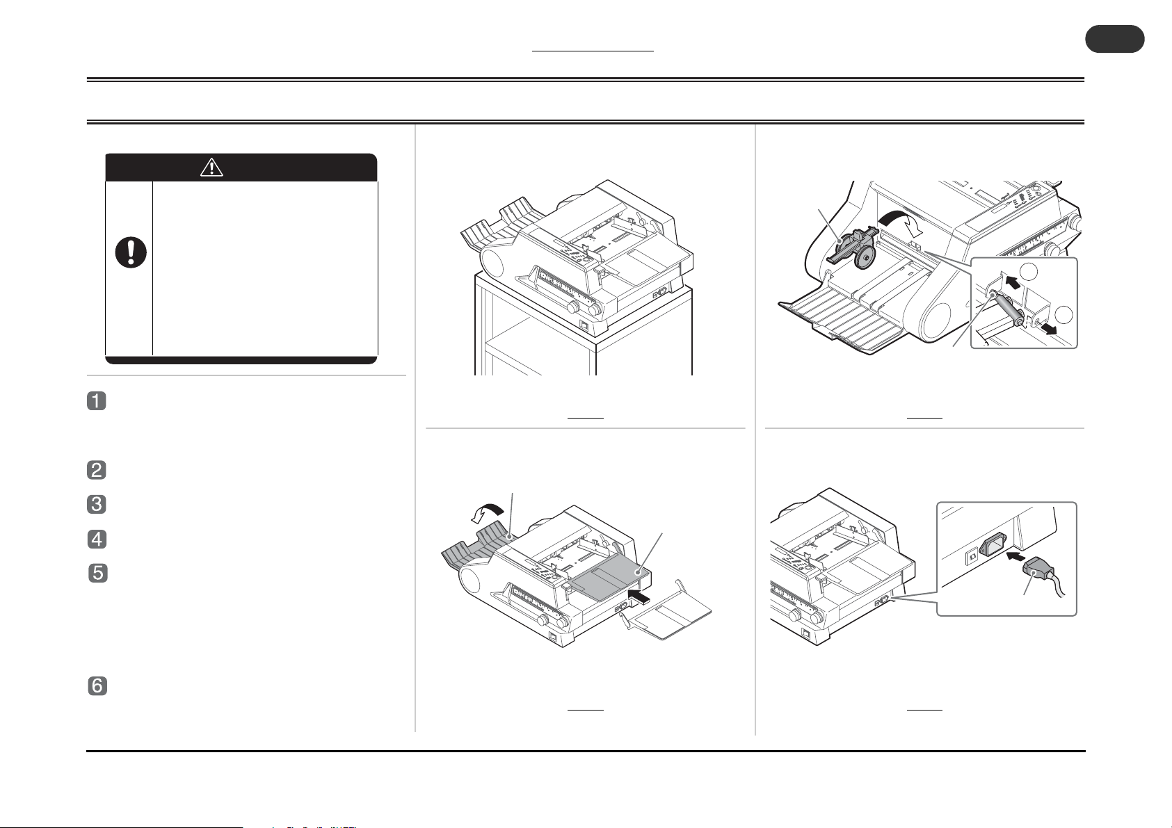
Open the package and take the folder
out of the box.
- Take all the accessories out of the box, too.
Place the folder on the table. (Fig.1)
Attach the support table. (Fig. 2)
Open the delivery tray. (Fig. 2)
Attach the delivery roller assembly.
(Fig. 3)
- Insert the rear end of the pin in the rear hole, and
push back in the direction shown by arrow 1. Pull
the front end of the pin into the front hole in the
direction shown by arrow 2.
Plug the power cable to the PF-P3100.
(Fig. 4)
Delivery Tray
Fig.1
Fig.2
Support Table
503013
1_1_1C
Fig.3
Fig.4
Power Cable
503013
1_1_1D
Page 7
1 Installation and Mechanism
Lock Screw for Control Panel
B4-8B
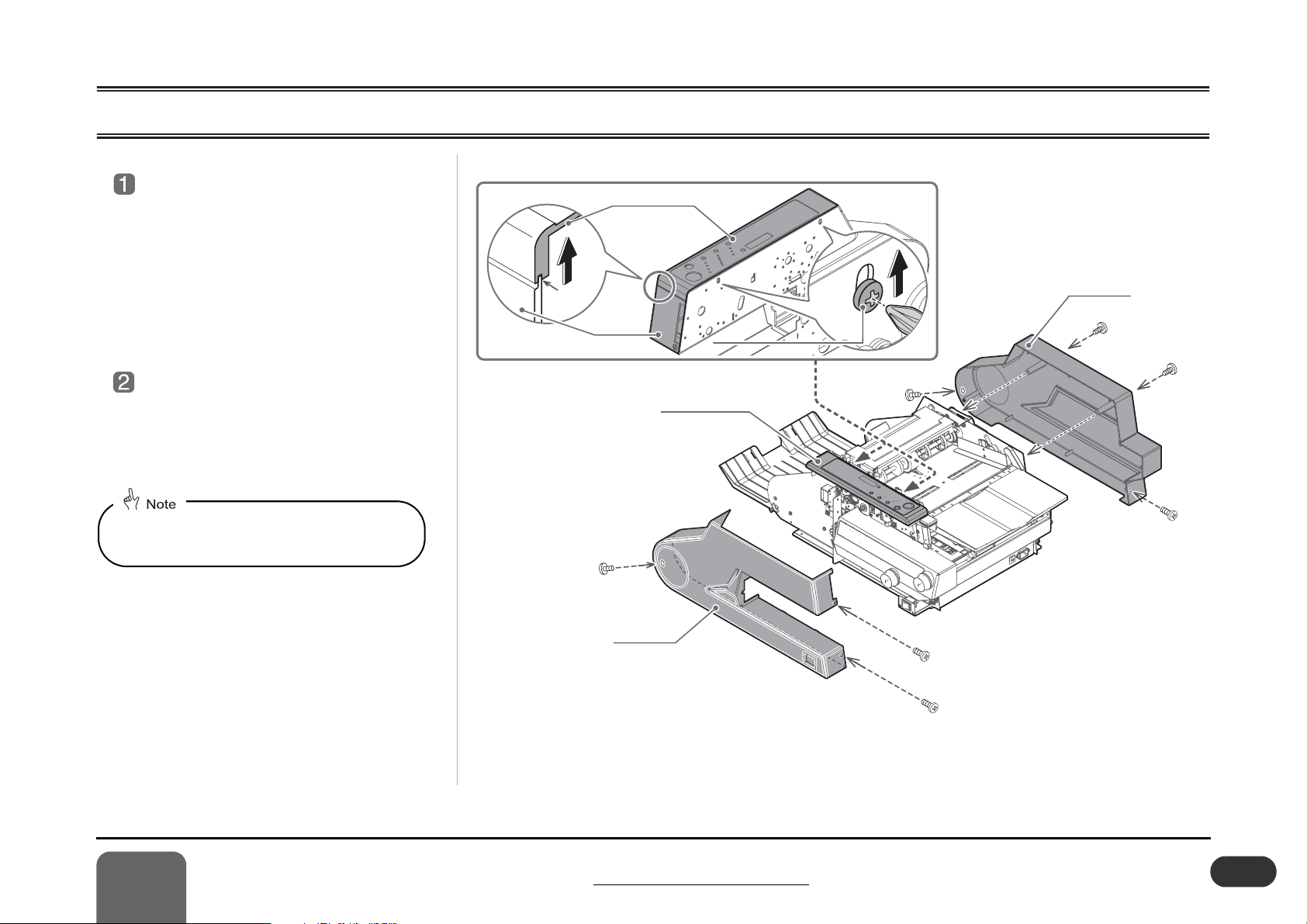
1 - 2 Main Cover Removal
Remove the cover F.
- Remove three lock screws.
- Loosen two lock screws of the control
panel.
- Lift the control panel, and disengage the
control panel from the cover F.
- Remove the cover F.
Remove the cover R.
- Remove four lock screws.
- Remove the cover R.
When attaching the cover, it is easier to attach
the cover once the buckle chute unit is
removed.
Engagement
Control Panel
Cover F
Cover F
Lock Screw for Control Panel
Lock Screw for Control Panel
Control Panel
B4-8B
B4-8B
Cover R
B4-8Bx4
1
Installation and Mechanism
1 - 2 Main Cover Removal
B4-8Bx3
503013
1_2_1A
1-3
Page 8
1 Installation and Mechanism
A
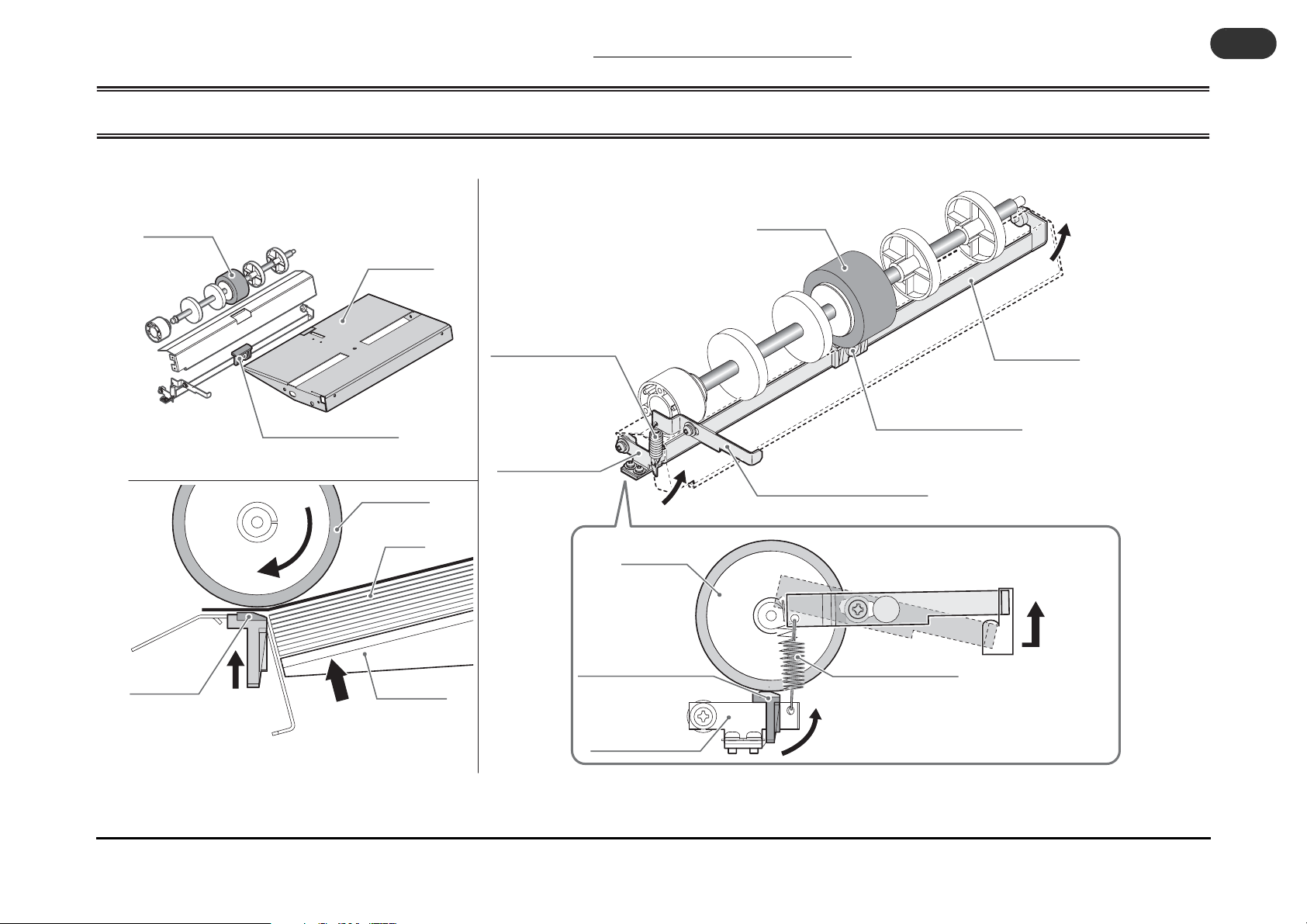
1 - 3 Buckle Chute Removal
1 - 3 Buckle Chute Removal
1-4
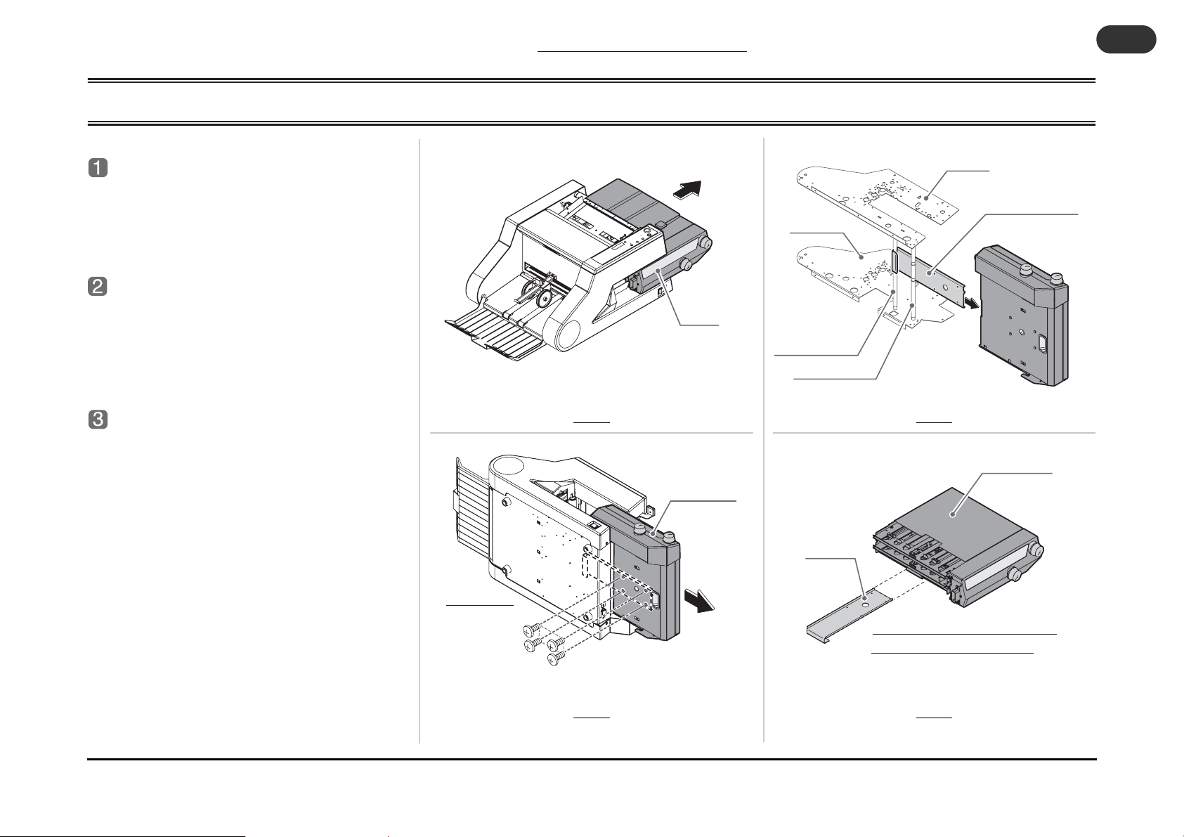
Pull out the buckle chute.
- Pull out the buckle chute to the arrow direction
slowly until it stops. (Fig. 1)
Remove the stopper bracket.
- Remove four lock screws of the stopper bracket
on the buckle chute at the bottom of the buckle
chute. (Fig. 2)
Remove the buckle chute.
- Pull out the buckle chute to the arrow direction to
remove. (Fig. 3)
- Remove the stopper bracket from the main body.
(Fig. 3)
Fig.1
Buckle
Chute
503013
1_3_1
Buckle Chute
Frame R
Support Shaft 1
Support Shaft 2
Stopper
Bracket
Fig.3
Frame F
Stopper Bracket
Buckle Chute
503013
1_3_1C
Bottom Plane
Buckle Chute and Stopper Bracket
503013
Lock Screws
B4-6B4
1_3_1B
Fig.2
separated from the main body
Fig.4
503013
1_3_1D
Page 9
1 Installation and Mechanism
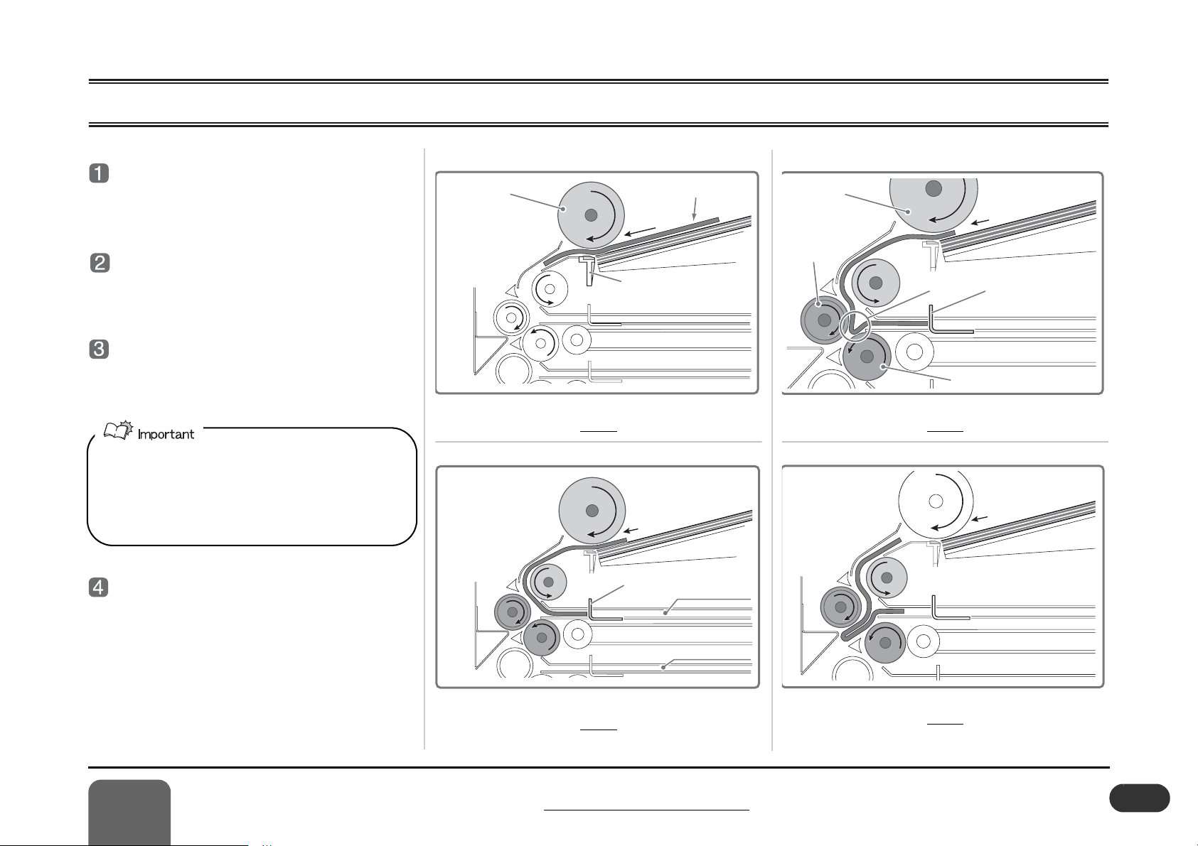
1 - 4 Mechanism of Folding
Sheets are fed.
- The feed roller rotates and feeds sheet one by one
to the buckle chute. (Fig. 1)
The sheet hits the stopper.
- The sheet hits the stopper on the 1st buckle chute
and stops. (Fig. 2)
The sheet is bent slightly.
- The sheet stopped by the stopper is bent, and the
fold rollers catch the sheet bend. (Fig. 3)
- When the folding speed is set to “High”, the amount of
sheet bend is slightly changed. Set the stopper position 1 mm (0.04”) shorter than the normal setting.
- When the heavier sheet is folded, the amount of sheet
bent becomes smaller. Set the folding speed to “High”
to create bigger sheet bend.
The sheet is folded.
- The fold rollers catch the bending part of sheet
and sheet is folded.
- The fold position changes depending on the stopper position.
Feed Roller
Fig.1
Sheets
Double Feed Stop Plate
Stopper
1st Buckle Chute
2nd Buckle Chute
503013
1_4_1A
Feed Roller
Fold Roller
Bending Part
Fold Roller
Fig.3
Stopper
503013
1_4_1B
1
Installation and Mechanism
503013
1_4_1C
Fig.2
1 - 4 Mechanism of Folding
Fig.4
503013
1_4_1D
1-51-5
Page 10

1 Installation and Mechanism
A
Slide Spring
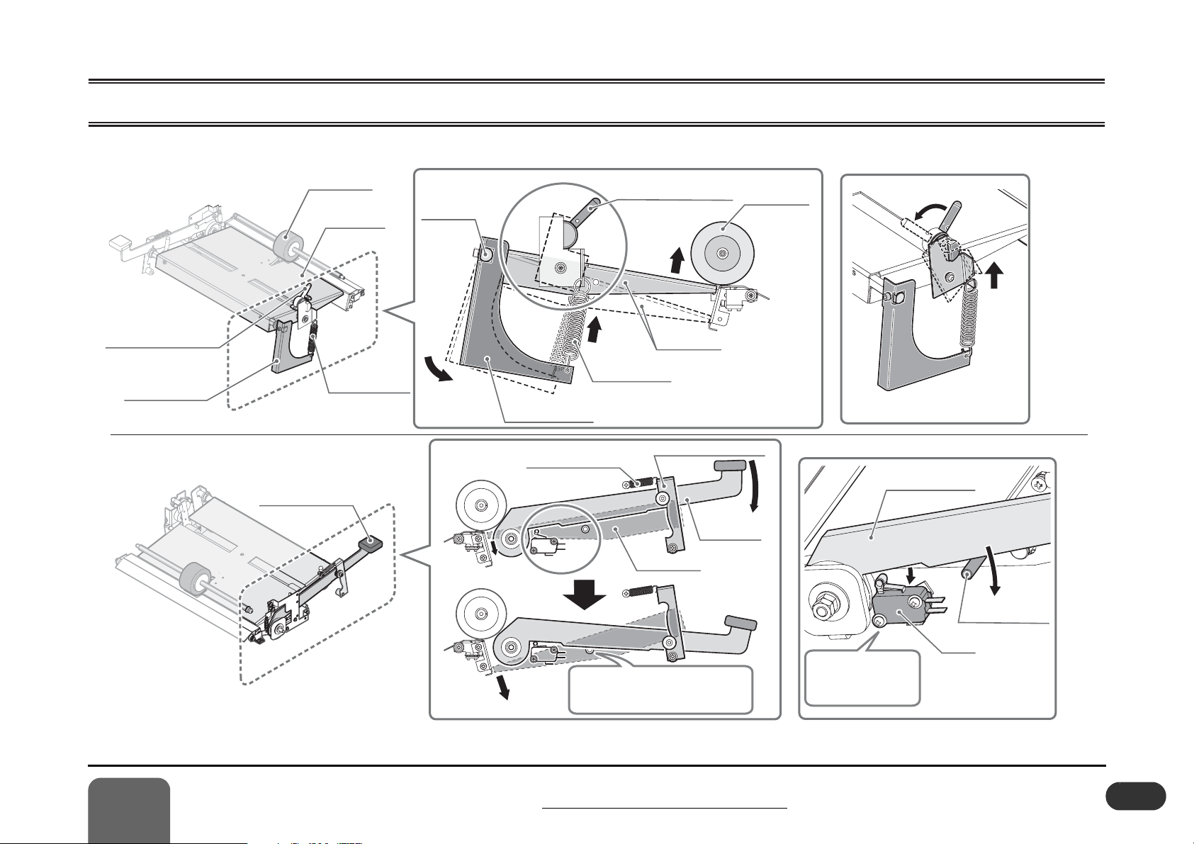
1 - 5 Feed Table
Feed Table Sheet
Actuator
Sheet Guide
Support Table
1 - 5 Feed Table
The sheet guides can be
adjusted on this pivot.
Slide Spring
Slide Spring
1-6
Feed Angle
Adjusting Mechanism
Feed Table Sheet
Actuator
S12
Sheet Detection
Switch
This rod is
eccentric.
Feed Angle Adjusting Mechanism
Eccentric Rod
Lever Knob
Guide Shaft
The lever knob plates hold
the guide shaft and this fix
the guide position.
Slide Block
Guide Shaft
Slide SpringSlide Spring
503013
1_5_1
Page 11
1 Installation and Mechanism
(Strong)
(Normal)
Section B
Section A
Section A
Section B
1 - 6 Table Up/Down Mechanism
Feed Roller
Feed Table
Feed Table
Fulcrum Shaft
Section A
Section A
Feed Table
Pressure Adjusting Lever
Feed Roller
Section A
Section A
(Strong)
(Strong)
(Normal)
(Normal)
Feed Table
Pressure Adjusting Lever
Pressure Lever
Feed Tray Lever
Feed Table
Pressure Spring
Pressure Lever
Lever Cam Spring
Section B
Section B
Feed Table
Feed Table
Pressure Spring
Feed Tray Lever Cam
Feed Tray
Lever
Feed Table
The tip of the feed table lowers
when the feed tray lever pushes
this shaft down.
This switch detects
that the feed table
is lowered.
Set the lever to "Strong" to
increase the feed table pressure.
Section B
Section B
Feed Tray Lever
S12
Feet Table
Pushdown Shaft
503013
1_6_1A
1
Installation and Mechanism
1 - 6 Table Up/Down Mechanism
1-7
Page 12
1 Installation and Mechanism
M10 Main Motor
(DC brushless motor)
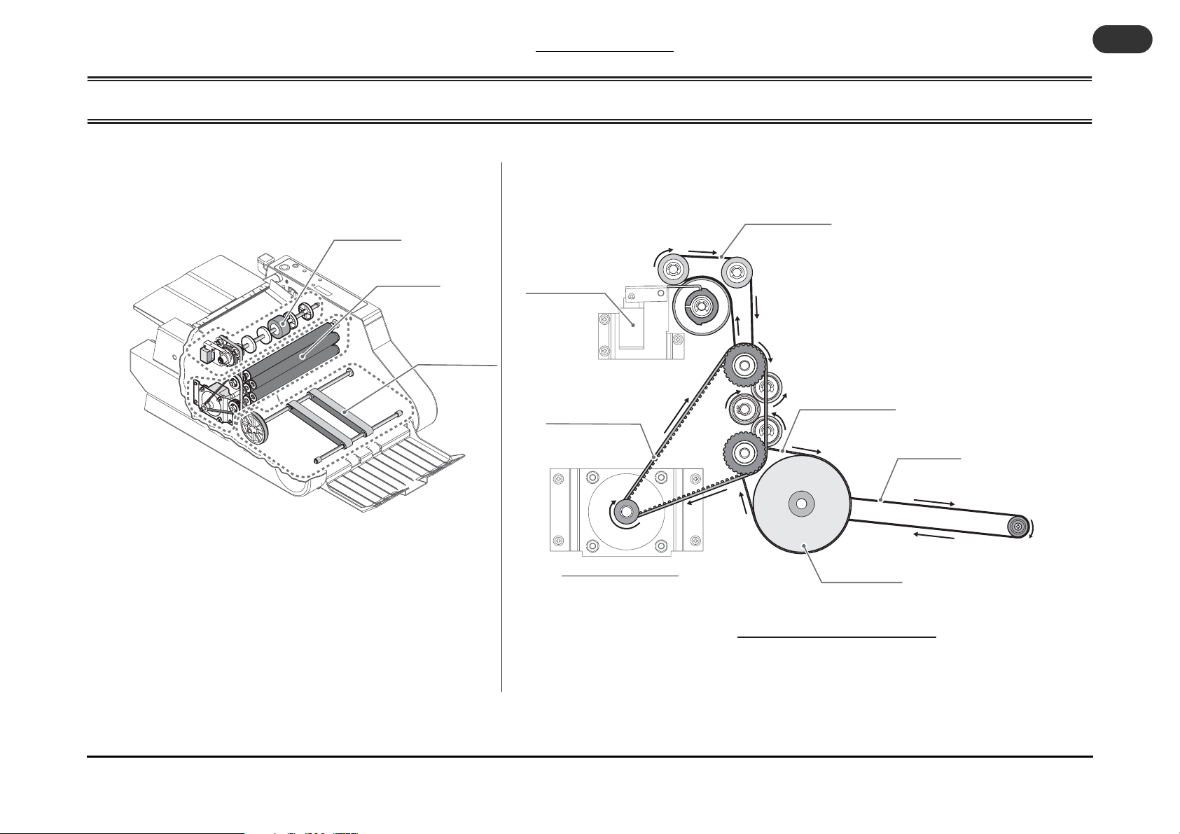
1 - 7 Drive Section
Feed Roller
1 - 7 Drive Section
1-8
Feed Drive Belt
Fold Roller
Delivery Section
Clutch Solenoid
Drive Timing Belt
M10 Main Motor
(DC brushless motor)
Delivery Drive Belt
Delivery Belt
Conveyor Pulley
Power Transport System
503013
1_7_1A
Page 13
1 Installation and Mechanism
A
Inner diameter of the clutch spring
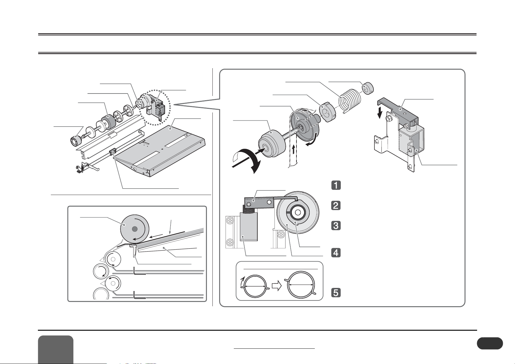
1 - 8 Feed Roller Section
Free Bearing
Fixed Bearing
Feed Roller Shaft
Feed Roller
Feed Roller
Clutch Unit
Double Feed Stop Plate
Sheet
Double Feed Stop Plate
Feed Table
Feed Table
Clutch Stopper
Clutch Pulley
Fixed Bearing
Feed Roller
Insert the feed roller shaft.
Clutch Lever
Clutch SolenoidClutch Solenoid
Inner diameter of the clutch spring
Twist
Inner
Diameter
Clutch Spring
Clutch
Stopper
Clutch Pulley
Enlarged
Inner
Diameter
Clutch Bushing
Clutch Lever
Clutch
The feed roller rotates to the
arrow direction and feeds sheet.
The rotation of the clutch stopper
stops when the clutch lever lowers.
The clutch spring is twisted to
the arrow direction, and the inner
diameter of
the clutch spring is enlarged.
Since the inner diameter of the
clutch spring is enlarged, the power
transmission to the feed roller shaft is
shut off, and the clutch bushing is
slipped on the clutch pu
lley.
The feed roller does not rotate although
the clutch pulley rotates.
Solenoid
503013
1_8_1
1
Installation and Mechanism
1 - 8 Feed Roller Section
1-9
Page 14
1 Installation and Mechanism
1 - 9 Double Feed Stop Section
1 - 9 Double Feed Stop Section
1-10
Feed Roller
Double Feed
Stop Plate
Double Feed Stop Plate
Double Feed
Stop Pressure
Feed
Pressure
Feed Table
Feed Roller
Sheet
Feed Table
Plate Pressure Spring
Plate Stand Lever
Double Feed Stop Plate
Plate Bracket Lever
Feed Roller
Feed Roller
Double Feed Stop Plate
Plate Pressure Adjusting Plate
Plate Pressure Spring
Second sheet is stopped by the
friction of the double feed stop plate.
Plate Bracket
Plate Pressure Adjusting Plate
Plate Pressure
Low"
"
503013
1_9_1A
Page 15
1 Installation and Mechanism
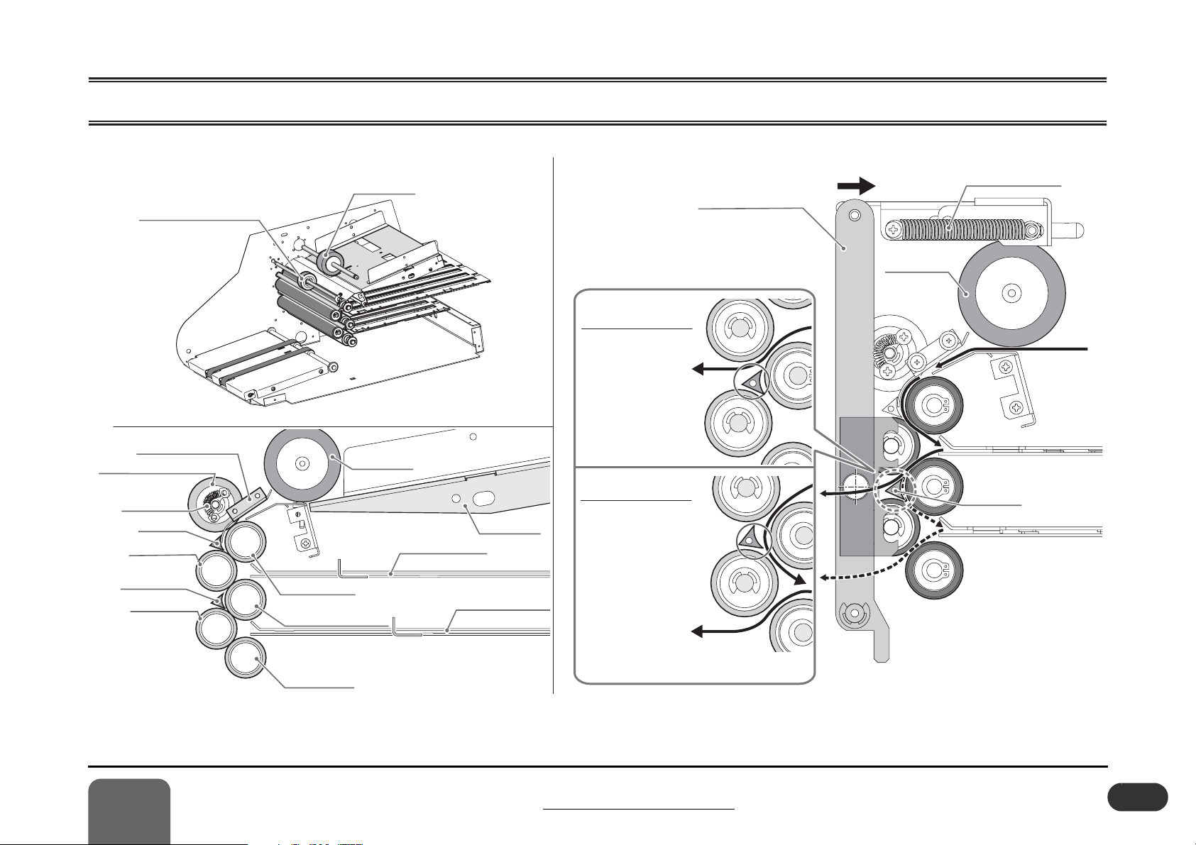
Solenoid O
N =
When the tray gate
is at right.
- When the solenoid
turns ON, the tray gate
comes close to the third
roller.
- The sheet that comes
through the second and
third
roller goes over
the tray gate and is
delivered.
Solenoid OFF =
When the tray gate is at left.
-
When the solenoid
turns OFF, the tray gate
moves to the left and
makes a space between
the tray gate and the
third roller.
- The sheet that comes
through the second and
third roller deflects at
the tray gate, then goes
to the second buckle
chute through the third
and fourth roller.
1 - 10 Fold Roller Section
Transport Rubber Roller
Upper Guide Plate
Transport Rubber Roller
Hold Spring
R Gate
Fold Roller 2
Tray Gate
Fold Roller 4
1
Installation and Mechanism
2
4
1
3
5
Fold Roller 1
Fold Roller 3
Fold Roller 5
Feed Roller
Feed Roller
1st Buckle Chute
Solenoid O
When the tray gate
- When the solenoid
turns ON, the tray gate
comes close to the third
roller.
- The sheet that comes
through the second and
third
Feed Table
2nd Buckle Chute
roller goes over
the tray gate and is
delivered.
Solenoid OFF =
When the tray gate is at left.
When the solenoid
turns OFF, the tray gate
moves to the left and
makes a space between
the tray gate and the
third roller.
- The sheet that comes
through the second and
third roller deflects at
the tray gate, then goes
to the second buckle
chute through the third
and fourth roller.
1 - 10 Fold Roller Section
N =
is at right.
Press the fold driven rollers.
Roller Pressure Link
2
4
2
4
Fold Roller Spring
Feed Roller
Sheet
3
1
2
3
Tray Gate
3
4
1st Buckle
nd Buckle
2
5
5
503013
1_10_1A
1-11
Page 16
1 Installation and Mechanism
A
When Solenoid ON:
When Solenoid OFF:
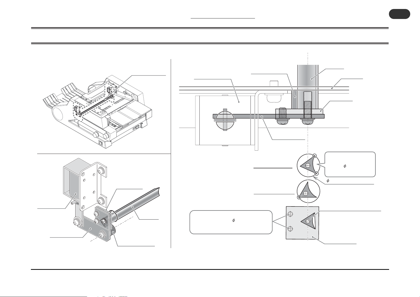
1 - 11 Tray Gate Section
1 - 11 Tray Gate Section
1-12
Gate Solenoid
(front)
Gate Lever (front)
Tray Gate Section
Gate Bracket
Tray Gate
Gate Fulcrum Shaft
Gate Fulcrum Shaft
Gate Solenoid (front)
When Solenoid ON:
When Solenoid OFF:
Adjust the tilt of the tray gate and the
internal contact with the 14 hole by adjusting
the tray gate bracket using these two holes.
Gate Lever (front)
Tray Gate
Side Plate
Gate Bracket
The stop position of the tray
gate is where the gate hits
inside the 14 hole on the
side plate.
14 hole on the side plate
Lock the tray gate with this screw.
Tray Gate Bracket
503013
1_11_1
Page 17
1 Installation and Mechanism
A
M10
M10M10M10M10M10M10
M10
Tension Adjustment
of the Delivery Belt
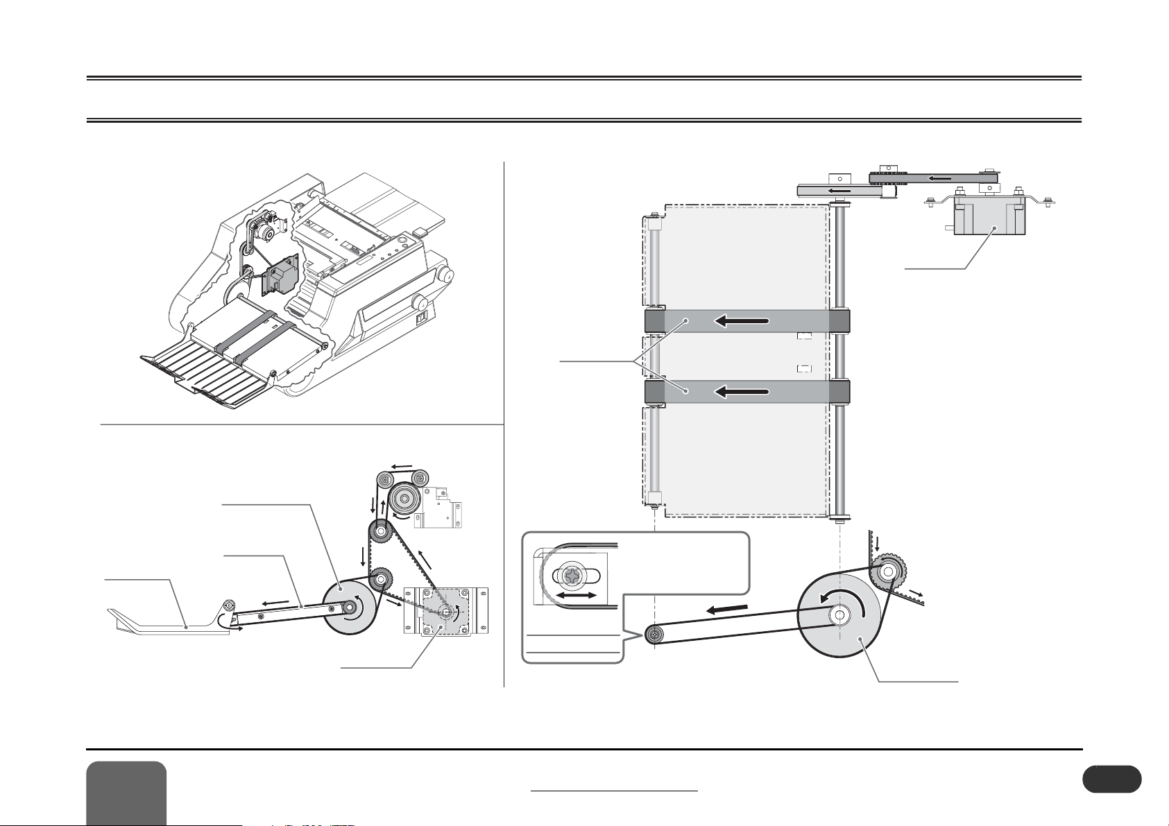
1 - 12 Delivery Section
M10
M10
M10M10M10
Main Motor
M10
M10
Delivery Tray
Conveyor Pulley
Delivery Belt
Main Motor
M10M10
Delivery Belts
Tension Adjustment
of the Delivery Belt
Adjust the belt tension
by fixing position of the
shaft.
Conveyor Pulley
503013
1_12_ 1
1
Installation and Mechanism
1 - 12 Delivery Section
1-13
Page 18

1 Installation and Mechanism
Timing Belt
1st Stopper
Stopper
2nd Buckle
LEDLED
1st Buckle
Home Position of Buckle Chute
21
1st Buckle
Chute Stopper
2nd Buckle Chute Stopper
Stopper Unit
21
22
Proximity Sensor Unit
Home Position of Buckle Chute Stopper
2nd Buckle
Section A
Section A
Lock Screws
Lock
Screws
Lock
Screws
Stopper
1 - 13 Buckle Chute Section
1 - 13 Buckle Chute Section
1-14
Home Position of Buckle Chute Stopper
Set the first and second stopper at 57 mm (2.2") from the
entrance of the buckle chute. Align the stopper pointer to the leftmost LED on the buckle chute.
57 mm (2.2")
Stopper
Stopper
Stopper
Stopper
57 mm (2.2")
Buckle Chute
Section
Stopper Pointer
LED
LED
Stopper Pointer
1st Buckle
2nd Buckle
2nd Buckle
Home Position of Buckle Chute
Stopper
Move Shaft
Timing Pulley
Timing Belt
Timing Belt
Handwheel
Handwheel
1st Stopper
1st Stopper
Timing Pulley
2nd Buckle
2nd
Stopper
1st Buckle
Stopper
Move Shaft
Section A
Section A
Proximity Sensor: B21
Lock Screws
Lock Screws
Lock
Lock
Screws
Screws
Section A
Section A
Sensor Bracket
Proximity Sensor Unit
2nd Buckle Chute Stopper
Loosen the lock screws,
and then adjust the position
of the stopper pointer.
Stopper Unit
Proximity Sensor for 1st Buckle Chute : B21
Proximity Sensor for 2nd Buckle Chute : B22
When the stopper moves
forward to the gate of the
buckle chute, the whole
sensor bracket slide to the
Slide
1st Buckle
Chute Stopper
arrow direction.
Sensor
Spring
503013
1_13_1A
Page 19

2 Service Mode and Error Code
2-1............... Functions of Service Mode .................................................. 2-2
2-2............... Error Code Chart.................................................................. 2-3
2
Service Mode and Error Code
2-1
Page 20

2 Service Mode and Error Code
2 - 1 Functions of Service Mode
2 - 1 Functions of Service Mode
2-2
The service mode is the functions listed in the chart to
the right can be performed by pressing the power
switch and the other buttons together.
To exit the service mode, turn off the power switch.
Start/Stop Button
Display
Sheet Size Select Button
Clear Button
Test Button
Power Switch : ON
503013
2_1_1A
Service Mode How to Enter What You Can Do in This Mode
Memory writing
error reset mode
Life counter check
mode
Software version
check mode
Error-ignoring
check mode
S13: Feed Table
Sheet Detection
switch ignoring
mode
S12: Feed Bar
switch ignoring
mode
Turn on the power switch while pressing
the Start/Stop, Test and Clear buttons on
the control panel simultaneously, and hold
down the buttons for 5 seconds until
buzzer sounds.
Turn on the power switch while pressing
the Start/Stop button on the control panel,
and hold down the button for 5 seconds
until buzzer sounds.
Turn on the power switch while pressing
the Start/Stop, Test and Sheet Size Select
buttons on the control panel simultaneously, and hold down the buttons for 5
seconds until buzzer sounds.
Turn on the power switch while pressing
the Start/Stop and Test buttons on the control panel simultaneously, and hold down
the buttons for 5 seconds until buzzer
sounds.
1. Enter into the error-ignoring check
mode.
2. Press the Clear button for 5 seconds
until buzzer sounds.
1. Enter into the error-ignoring check
mode.
2. Press the Start/Stop button for 5 seconds until buzzer sounds.
When “E7” (memory error) occurs, and the
machine is not recovered by turning the power
off and on, the memory can be reset in this
mode. (This memory will be returned to the
default value.)
Life counter can be displayed. The last two
digits are not indicated.(For example “10” is
indicated when 1,000 sheets were folded.)
The life counter is cleared to “0” by pressing
the Clear button for 5 seconds.
Current software version is displayed, for
example “v0.77”.
In this mode, error is not detected at all. Operation can be performed as usual. (“8888” is
displayed when the Clear button is pressed.)
In this mode, the folder can be used even if
S13 Feed Table Sheet Detection switch is broken down.
In this mode, operator can use the folder even
if S12 Feed Bar switch is broken down.
Page 21

2 Service Mode and Error Code
2 - 2 Error Code Chart
Error
Code
E1
E2
E3
E4
E5
Cause and Solutions
[Cause] The fold section cover opens while the motor rotates. (The S10 fold section cover switch turns Off.)
[Solution] Close the fold section cover. If the same error still occurs, check wiring/connection between S10 and QPM-243. If the S10 fold section cover switch is On,
LED L27 on QPM-243 turns off. If the same error still occurs, replace S10. If the same error still occurs, replace the QPM-243 control board.
[Cause] The X20 buckle connector is removed while the motor rotates. (The buckle chute is removed from the X20 buckle connector.)
[Solution] Insert the buckle chute so that the X20P connector on the buckle chute is connected to the X20R connector on the folder correctly. If the same error still
occurs, check wiring/connection between X20 and QPM-243. If the buckle chute is inserted properly, LED L26 on QPM-243 lights. If the same error still
occurs, replace the QPM-243 control board.
[Cause] The A10 motor driver alarms. (The M10 main motor is overloaded.)
[Solution] Check if a sheet is not caught between the mechanical sections driven by the M10 main motor. Check if the drive shaft of the M10 main motor tries to rotate
when the power is applied. Check if the drive shaft of the M10 can be rotated smoothly by hand when the drive belt is removed. If it is OK, check wiring/connection between M10 and A10, and A10 and QPM-243. If it is OK, replace the A10 motor driver. If it is OK, replace the QPM-243 control board.
[Cause] The F2 fuse (3.15 A) on the QPM-243 control board is blown. (24VDC circuit from the control board shorts out, or the fuse is deteriorated.)
[Solution] Check if the wiring is not caught in the machine covers and does not short out. Replace the F2 fuse. (If the fuse is not blown, LED L24 on QPM-243 lights.)
[Cause] The third and fourth contact point for the K01 interlock relay is welded. (Short-out condition) ---------- The interlock relay is defective.
[Solution] Replace the K01 interlock relay.
E6
[Cause] The third and fourth contact point for the K01 interlock relay is not connected. (Open condition) ---------- The interlock relay is defective.
[Solution] Replace the K01 interlock relay.
2
Service Mode and Error Code
2 - 2 Error Code Chart
2-3
Page 22

2 Service Mode and Error Code
2 - 2 Error Code Chart
[Cause] Memory reading error: EPROM information can not be read when turning on the power switch.
2-4
E7
[Solution] Reset the memory using the “Memory Reading Error Reset Mode” in the service function, and operates the folder with the default setting. If the same error
still occurs, replace the QPM-243 control board.
Page 23

3 Adjusting and Checking Procedures
3-1............... Buckle Chute Stopper Angle Adjustment.............................. 3-2
3-2............... Feed Clutch Unit Adjustment ............................................... 3-3
3-3............... Tray Gate Position Adjustment ............................................ 3-4
3-4............... Belt Tension Adjustment ...................................................... 3-5
3-5............... Delivery Belt Replacement .................................................. 3-6
3-6............... Micro-switch Adjustment ...................................................... 3-7
3
Adjusting and Checking Procedures
3-1
Page 24

3 - 1 Buckle Chute Stopper Angle Adjustment
A
SheetSheetSheet
1st buckle adjustment
Do not loosen.
2nd buckle adjustment
Do not loosen.
Stopper
2nd Buckle
LEDLED
Stopper
3 Adjusting and Checking Procedures
3 - 1 Buckle Chute Stopper Angle Adjustment
3-2
- Check the fold skew.
- Determine which stopper requires adjustment.
- Pull out the buckle chute and open the top cover. (Fig.1)
- Loosen the timing pulley on the rear of the 1st buckle
- Loosen the timing pulley on the rear from the square
- Insert the scale from the entrance of the buckle chute
- Align the stopper pointer to the left-most lamp on the
503013
5_4_1
Check the folded sheets which was fed
correctly.
Adjust the 1st buckle chute stopper
angle.
chute and adjust the stopper angle. (Fig.2) (Do not
loosen the timing pulley on the handwheel side as it
is a reference side.)
Adjust the 2nd buckle chute stopper
angle.
window for adjustment at the bottom of the buckle
chute unit, and adjust the stopper angle. (Fig.3) (Do
not loosen the timing pulley on the handwheel side as
it is a reference side.)
Check the stopper home position.
and set the stopper at 57 mm (2.2"). The stopper should
be leveled at the front and rear.
buckle chute. (See Section 1 - 13 for pointer adjustment)
(Fig.4)
Pull out the buckle chute to the arrow direction
slowly until it stops. See Section 1-3-1 for
buckle chute separation.
Fig.1 Buckle Chute
1st buckle adjustment
Adjust the stopper angle
using the timing pulley on the rear.
Sheet
Sheet
Stopper
Do not loosen.
503013
3_1_1B
Fig.2 Angle Adjustment 1
Top Cover
Buckle Chute
503013
3_1_1A
Timing Pulley
Allen Wrench
(2mm/0.08")
This is
registering
side.
2nd buckle adjustment
Bottom Plane
Square window for 2nd stopper
adjustment
Do not loosen.
This is the
reference side.
Timing Pulley
Allen Wrench
(2mm/0.08")
Adjust the stopper
angle using the timing
pulley on the rear.
503013
3_1_1C
Fig.3 Angle Adjustment 2
Set the first and second stopper at 57 mm (2.2")
from the inner side of the buckle chute. Align the
stopper to the left-most lamp on the buckle chute.
See Section 1-13.
57 mm (2.2")
Stopper
Stopper
Stopper
Stopper
57 mm (2.2")
Stopper Pointer
LED
LED
Stopper Pointer
1st Buckle
2nd Buckle
2nd Buckle
503013
3_1_1D
Fig.4 Buckle Chute Stopper Home Position
Page 25

3 Adjusting and Checking Procedures
Plunger
Clutch
Solenoid
When Y01 is On
G
FC-6
SARI-10
When Y01 turns to Off
G
G
G
G
3 - 2 Feed Clutch Unit Adjustment
- The feed clutch activates when start and stop
feeding the sheet, and Short fold and Accordion
fold, which the sheet enters into the first buckle
chute deeply, are selected.
- The feed clutch activates every time the clutch
stopper rotates, and waits until the former sheet
passes so that the second sheet does not hit the
first sheet and jams. (The feed clutch does not
activate for the continuous feeding on other fold
patterns.)
Check and adjust the gap between
the clutch lever and the clutch stop-
per.
Support Roller
Feed Roller Shaft
Feed Roller
Free Bearing
Fixed Bearing
Clutch Unit
Clutch Housing
Fixed
Bearing
FC-6
Roller
Clutch
Bearing
W8
SARI-10
Free Bearing Spring
Clutch Bush
Clutch Stopper
Clutch Pulley
"G" shows grease supply point.
Free
Bearing
Bearing
Clutch Spring
- Remove the rear cover to access the clutch section.
- Turn off the power switch.
- Check that the clutch stopper is stopped by the
clutch lever when the Y01 clutch solenoid is Off.
(Fig.2)
- Adjust the position of the solenoid bracket so that
when the plunger of Y01 is pushed down and the
solenoid Y01 is turned on, the gap between the
circumference of the clutch stopper and the tip of
the clutch lever becomes 0.5 to 1.0 mm (0.02" to
0.04").
- Lock the bracket using the bracket locking screw.
(Fig.3)
3
Clutch Lever
Y01
When Y01 turns to Off
1. The tip of the clutch lever is caught by the step of the clutch stopper.
2. The clutch stopper stops rotating.
3. The inner diameter of the clutch spring enlarges.
4. Torque to the feed roller is not transmitted.
Adjusting and Checking Procedures
Clutch Pulley
Fixed Bearing
Clutch Stopper
Clutch Spring
When Y01 is On
Loosen the bracket locking screw and adjust the position of the
solenoid bracket so that the gap between the clutch
lever and the clutch stopper becomes 0.5 to 1.0 mm (0.02" to 0.04").
3 - 2 Feed Clutch Unit Adjustment
Y01
Clutch Lever
Plunger
Plunger
Clutch
Clutch
Solenoid
Solenoid
Solenoid Bracket
Gap 0.5 to 1.0 mm
(0.02" to 0.04")
Clutch Spring
Clutch Stopper
Bracket Locking Screw
503013
3_2_1A
3-3
Page 26

3 Adjusting and Checking Procedures
Y02
No.3No.3
No.5No.5
When Y02 (Y03 on far side) is On,
the tray gate comes close to the third roller.
ON
Solenoid ON:
Solenoid OFF:
Y02
No.3No.3
No.5No.5
When Y02 (Y03 on far side) is Off,
the tray gate comes off from the third roller.
OFF
4
3 - 3 Tray Gate Position Adjustment
Depending on the position of the tray gate, sheets are
delivered, or folded again.
The stop position of the tray gate is where the gate
hits inside the 14 hole on the side plate.
Y02
Y02
Remove the second and fourth rollers.
3 - 3 Tray Gate Position Adjustment
No.3
No.3
Y02
Y02
No.3
No.3
3-4
Loosen the locking screws on the gate
holder. (Fig.2)
Lock the gate holder.
- Press the gate holder to the third roller direction and
tighten the locking screws. (Fig.4)
Adjust the solenoid position.
- Position the Y02 (Y03) solenoid so that when the plunger
of the solenoid is pushed in, two tip of the gate touches
the 14 hole on the side plate. Tighten the locking
screws in that position. (Fig.4)
Check the position of the tray gate.
- Remove the drive timing belt. Keep pushing plunger of
the Y02 (Y03) solenoid in and turn the third roller manually. Check that the roller turns without any noise by hitting the gate on the roller.
ON
Tray Gate
When Y02 (Y03 on far side) is On,
the tray gate comes close to the third roller.
Fig.1
Gate Solenoid (front)
503013
3_3_1B
Gate Fulcrum Shaft
Gate Holder Locking Screw
Gate Lever (front)
Solenoid ON:
Solenoid OFF:
(except for single fold)
Touch in one place
Fig.2
No.5
No.5
Tray Gate
Side Plate
Gate Holder
The stop position of
the tray gate is
where the gate hits
inside the 14 hole
on the side plate.
(Two places)
14 Side Plate Hole
503013
3_3_1A
OFF
Tray Gate
When Y02 (Y03 on far side) is Off,
the tray gate comes off from the third roller.
Fig.3
1
Y02Y02
2
Push In
Solenoid
Locking
Screw
Fig.4
3
These screws can also adjust
the tilt of the gate.
No.5
No.5
503013
3_3_1C
503013
3_3_1D
Touches the 14 hole
(two places)
14
Lock the Y02 (Y03)
solenoid when top
of the tray gate
touch the side
plate in two places.
Page 27

3 Adjusting and Checking Procedures
Tension Adjustment
Drive Timing Belt
Feed Drive Belt
Delivery Drive Belt
3 - 4 Belt Tension Adjustment
Drive Timing Belt Tension
The tension of the drive timing belt is
adjusted by the mounting position of the
drive motor (M10).
If the belt is tightened too much, it may
cause vibration of the belt by the motion of
the machine. Do not tighten the belt too
much.
Drive Timing Belt
When the belt is pushed by 200
gW at its center, the belt bends
by 3 to 4 mm (0.12" to 0.16").
Feed Drive Belt Tension
The tension of the feed drive belt is adjusted by
the attaching position of the tension roller. The
hole to fix the tension roller on the side plate is a
slotted hole.
Adjust by the tension roller.
Feed Drive Belt
When the belt is pushed by 500
gW at its center, the belt bends
by 3 to 4 mm (0.12" to 0.16").
Delivery Drive Belt
The tension of this belt
cannot be adjusted. Attach
only by the belt tension.
Delivery Belt Tension
The delivery belts are stretch, therefore, the belt
tension is not necessary to be adjusted for normal use. Lock the delivery roller shaft at the
center of the slot on the belt bottom plate.
If the delivery belt slips due to the long-time use,
set the delivery roller shaft at exit side of the
slot.
Delivery Belt
Belt Bottom Plate
503013
3_4_1B
Tension Adjustment
Adjust by the
mounting position
of the motor.
3
M10M10
Adjusting and Checking Procedures
Delivery Belt
503013
3_4_1A
3 - 4 Belt Tension Adjustment
Lock at the
center of the
slot.
Exit Side
3-5
Page 28

3 Adjusting and Checking Procedures
Delivery Drive Belt
Conveyor Pulley
Space
3 - 5 Delivery Belt Replacement
3 - 5 Delivery Belt Replacement
3-6
If the delivery belt slips, set the delivery roller shaft at
exit side of the slot on the belt bottom plate.
If the delivery belt slips even with setting the delivery roller
shaft at the exit side of the slot, replace the delivery belt.
Remove the cover F, R and the support
table.
Loosen two locking screws for the
delivery roller shaft.
- Loosen the locking screws for the delivery roller shaft at
exit side on the belt bottom plate. (Fig.2)
Remove the conveyor pulley.
- Remove the delivery drive belt.
- Remove the C snap ring for the conveyor pulley, and pull
out the conveyor pulley. (Fig.2)
- Pull out the PP4-18 parallel pin.
Displace the delivery roller drive shaft
to the front.
- Displace the delivery roller drive shaft to the front, and
make a space for belt replacement. (Fig.3)
Remove the belt bottom plate with the
delivery belt.
- Remove four locking screws on the belt bottom plate,
and remove the belt bottom plate with the delivery belt.
(Fig.4)
Attach new delivery belt in the reverse
order of removal.
- Lock the delivery roller shaft at the center of the slot on
the belt bottom plate.
Set Screws for
Delivery Roller Shaft
Belt Bottom
Plate
C Snap Ring
(STW-10)
Remove the snap
ring and pull out the
conveyor pulley.
Delivery Belt
Remove the
delivery drive
belt.
Pull out the
PP4-18
parallel pin.
Delivery Drive Belt
Delivery Drive Belt
Fig.1
Loosen the
locking screws
for the delivery
roller shaft.
Fig.2
Conveyor Pulley
Conveyor Pulley
Delivery Roller
503013
Drive Shaft
3_5_1A
503013
3_5_1B
Approach the
delivery belt to the
space on the back
for removal.
When attaching new
belt, align the arrow
direction with the
delivery direction.
Remove the delivery
belt and the belt bottom
plate from the frame.
Space
Space
Fig.3
Fig.4
Displace the delivery
roller drive shaft to the
front, and make a space
for belt replacement.
503013
3_5_1C
503013
3_5_1D
Locking Screw
Remove four
locking screws on
the belt bottom plate.
Page 29

3 Adjusting and Checking Procedures
0.5mm
(0.02")
0.5mm 0.5mm
0.5mm
(0.02")
: Fold Section Cover Switch
: Feed Bar Switch
: Feed Table Sheet Detection Switch
2
to 52 to
5
3 - 6 Micro-switch Adjustment
This section indicates the standard position for the
attachment of the three micro-switches used in this
machine.
S10: Fold Section Cover Switch
S10: Fold Section Cover Switch
- ON: When the fold section cover is closed.
- The actuator is pushed by the projection on the fold section cover.
- Attach with another 0.5 mm (0.02") push-in margin
when the actuator is pressed.
S12: Feed Bar Switch
- OFF: When the feed tray lever is pushed down.
- The actuator is pushed by the feed tray lever.
- Attach with another 0.5 mm (0.02") push-in margin
when the actuator is pressed.
S13: Feed Table Sheet Detection Switch
- The switch is activated when the actuator is pushed
down by the sheet on the feed table.
- The actuator is pushed by the detection lever.
- Attach with another 0.5 mm (0.02") push-in margin
when the actuator is pressed.
S10
0.5mm
Actuator
0.5mm
(0.02")
(0.02")
Check the clicking
sound when opening
the fold section cover
slowly.
503013
3_6_1A
S13
Fold Section
Cover
S12: Feed Bar Switch
There should be another 0.5 mm
(0.02") push-in margin when the
actuator is pressed.
Feed Tray Lever
S12
Feed Table
Pushdown Shaft
S13: Feed Table Sheet Detection Switch
5
5
to
to
2
2
mm
(0.08"
- 0.20")
ON when the actuator
is pushed by
2 - 5 mm (0.08" - 0.20").
3
Adjusting and Checking Procedures
3 - 6 Micro-switch Adjustment
3-7
Page 30

3 Adjusting and Checking Procedures
3-8
This page is intentionally left blank.
Page 31

4 Mechanical Troubleshooting
4-1 ............... Machine Is Not Powered On................................................. 4-2
4-2 ............... M10 Main Motor Does Not Rotate ....................................... 4-3
4-3 ............... Tray Gate Malfunctions ........................................................ 4-4
4-4 ............... Y01 Clutch Solenoid Does Not Activate................................ 4-5
4-5 ............... Buckle Chute Proximity Sensor Error................................... 4-6
4-6 ............... Delivery Belt Does Not Move................................................ 4-7
4
Mechanical Troubleshooting
4-1
Page 32

4 Mechanical Troubleshooting
0V
5V
4 - 1 Machine Is Not Powered On
The power cable is
unplugged from the outlet.
The power cable is
unplugged from the inlet.
Q01
circuit protector
is tripped.
The machine power
is not turned on.
Power is not
supplied to the outlet.
4 - 1 Machine Is Not Powered On
CN2
GND
GND
24V
24V
GND
GND
5V
5V
AC
100-240V
CN1
G01
Switching
Power Supply
5 VDC is generated
from the switching
power supply.
Tester
4-2
5V
Fuse on the QPM-243 control
P.C.B is blown.
(Refer to 6-3-1 for replacement.)
QPM-243 control board
is defective.
Wiring between the switching
power supply and the control
board is defective.
S00
power switch is not
turned on.
Power cable contact failure
Other
Tester
5 VDC is not generated
from the switching
power supply.
P.C.B. connector is
disconnected or not
connected correctly.
G01
switching power supply is
defective.
S00
power switch is defective.
Z01
noise filter is defective.
503013
4_1_1A
Page 33

4 Mechanical Troubleshooting
COM
NO
NC
Fold Section
Cover Switch
24V
GND
24V
24V
GND
X12
CON9CON9
CON10CON10
CON1CON1
S10
CN3
CN1
Motor Driver
A10
M10
24V
GND
X10
24V
GND
Buckle Chute
Connector
K01
X20
Interlock
Relay
DC Brushless Motor
SIG X20[L26]
SIG S10[L27]
QPM-243
Control Control
P.C.B.P.C.B.
50W
M10 : Main Motor Does Not Rotate
24 VDC Circuit
YEL
YEL
YEL
YEL
YEL
YEL
YEL
YEL
YEL
YEL
YEL
RED
BLK
ORN
ORN
YEL
YEL
YEL
YEL
YEL
YEL
YEL
YEL
YEL
YEL
BRN
RED
ORN
YEL
GRN
BLU
VIO
BRN
GRY
WHT
BLK
BRN
RED
ORN
GRN
YEL
BLU
VIO
GRY
M10
ORN
BLU
ORN
BLU
RED
BLK
24V
GND
CN1CN1
CN2CN2
CN3CN3
A10
CON10
CON11
X10
X11
YEL
K01
Interlock Relay
DC
Brushless
Motor
Motor DriverMotor Driver
[LED1]
SIG M10[L23]
QPM-243
Control
P.C.B
50W
A10 : Motor driver alarms
Interlock is activated
4 - 2 M10 Main Motor Does Not Rotate
M10 : Main Motor Does Not Rotate
24 VDC Circuit
503013
4_2_1A
Check the followings:
1. A sheet is not caught inside the mechani-
cal sections driven by the M10 main motor.
2. The drive shaft of the M10 main motor
tries to rotate when the power is applied.
The locking screws on timing pulley of the
M10 are not loosened.
3. The A10 motor driver does not send an
alarm out and stopped.
4
A10 : Motor driver alarms
1. LED L23 on QPM-243 control P.C.B. is not
turned off. (Normally lit)
2. LED1 on the A10 motor driver is not blink-
ing. (Normally lit)
3. LED1 is turned off when the A10 motor
driver is powered off.
Number of
blinks
2
3
4
5
Mechanical Troubleshooting
Signal Circuit
503013
4_2_1B
Check the followings:
Alarm
Stop with the overload-protection
function
One of the motor cable is disconnected
Overvoltage-protection function,
more than 27.6 VDC.
Undervoltage-protection function,
less than 18 VDC.
4 - 2 M10 Main Motor Does Not Rotate
Interlock is activated
Interlock Circuit
24V
COM
Fold Section
S10:
Cover Switch
NO
2
Buckle Chute
X20:
4
1
K01:
2
Connector
Interlock Relay
Motor
Driver
24V
3
4
A10
503013
GND
GND
4_2_1C
Check the followings:
1. The fold section cover is closed. (S10 is
not turned off.)
2. The X20 buckle chute connector is
inserted all the way (Pin 1 and 3, 2 and 4
of X20 is connected.)
3. The third and fourth contact point is not
opened by the K01 interlock relay activation.
4-3
Page 34

4 Mechanical Troubleshooting
Delivery
4 - 3 Tray Gate Malfunctions
- Tray gate closes (= Solenoid Y02 and Y03 turn On)
only while the single folding operation. To perform
the single folding, the tray gate comes close to the
third roller and the folded sheet is delivered to the
delivery belt.
4 - 3 Tray Gate Malfunctions
Do solenoids Y02 and Y03 function correctly?
Y03
Y02
4-4
Does the tray gate mechanism malfunction?
Locking Screws
Y02
Tray Gate
2
Delivery
3
4
Is a jammed sheet left inside?
Check the followings:
Tray Gate
503013
4_3_1A
1. There is no jammed sheet between the
tray gate and the fold roller.
[Confirmation]
Turn off the power switch and remove the
second and fourth rollers. Put your hand from
the delivery side, and check if the sheet is
jammed between the roller and the tray gate
on the infeed side by sliding your finger along
this gap.
Tray Gate
503013
4_3_1B
Check the followings:
1. When selecting single fold for the fold pat-
tern while the motor is rotating and the
feed table is raised, the plungers of Y02
and Y03 are pulled in.
2. When performing step 1, 24 VDC is mea-
sured on the connector XY02 and XY03.
3. Wiring and connection between Y02 -
XY02 - Pin 1 and 2 of CON8 on QPM-243,
and Y03 - XY03 - Pin 5 and 6 of CON8 on
QPM-243 are OK.
Plunger
Link
Gate Lever
In case either Y02 or Y03 malfunctions, the
tray gate can be switched by the other solenoid. Although, this makes the space
between the tray gate and roller at the side
where the solenoid malfunctions, and may
cause sheet jam.
Gate Fulcrum
Shaft
503013
4_3_1C
Check the followings:
1. The locking screw on the gate fulcrum
shaft is not loosened.
2. The connection of the gate lever and the
plunger is not loosened.
3. While the power is Off, the plunger can be
moved smoothly by hand.
4. The spring on the plunger is not cut. The
spring is not deformed and falls into the
plunger hole in the solenoid.
5. The locking screws of Y02 and Y03 are
fully tightened.
Page 35

4 Mechanical Troubleshooting
Plunger
Solenoid
Spring
BLU
BLU
BLU
BLU
BLU
CON8CON8
XY02
XY01XY01
XY03
Y02
Y01
Y03
BLU
BLU
BLU
BLU
BLU
BLU
BLU
QPM-243
Control
P.C.B
Clutch Clutch
SolenoidSolenoid
4 - 4 Y01 Clutch Solenoid Does Not Activate
- When Y01 clutch solenoid is On,
the feed roller rotates continuously to feed sheets.
When Y01 is Off,
the clutch lever stops the clutch stopper rotation, and
the feed roller stops.
- When performing short fold and accordion fold, sheet
enters into the first buckle chute deeply. To prevent
the second sheet from hitting the first sheet and
causing jam, “Intermittent feeding”
Other fold patterns
When performing single fold, letter fold, cross fold
and gate buckle fold, continuous feeding
- When performing short fold and accordion fold,
Y01 is turned off every time the clutch stopper
rotates and operate “Intermittent feeding”.
- When performing single fold and other folding
patterns, Y01 is On for continuous feeding.
4
is operated.
is operated.
Mechanical Troubleshooting
Does the feed clutch mechanism malfunction?
Gap
0.5-1.0mm
(0.02" - 0.04")
Spring
Spring
Clutch Lever
Plunger
Plunger
Y01
Clutch Stopper
Bracket Locking Screw
Solenoid
Solenoid
503013
4_4_1A
Check the followings:
1. When Y01 is On, the gap between the
clutch stopper and the clutch lever is 0.5
mm (0.02") to 1.0 mm (0.04").
2. The bracket locking screw is not loosened.
3. While the power is Off, the plunger can be
moved smoothly by hand.
4. The spring of the plunger is not deformed
and falls into the plunger hole in the solenoid.
5. The locking screws for Y01 are not loos-
ened.
4 - 4 Y01 Clutch Solenoid Does Not Activate
Does the solenoid Y01 malfunction?
503013
4_4_1B
Check the followings:
1. When short fold and accordion fold are
selected, Y01 turns OFF while feeding.
2. 24 VDC is measured on the connector
XY01 for the clutch solenoid. (0V when
operating intermittent feeding and Y01
turns off.)
3. Wiring and connection between the Y01 -
XY01- Pin 3, 4 of CON8 on QPM-243 is
OK.
4-5
Page 36

4 - 5 Buckle Chute Proximity Sensor Error
4 Mechanical Troubleshooting
4 - 5 Buckle Chute Proximity Sensor Error
4-6
- The proximity sensor inside the buckle chute detects
a sheet and counts the number of feeding. If there is
paper dust on the sensor detecting area, the
machine may not operate correctly.
- B22, 2nd buckle chute proximity sensor also decides
the operating timing of the feed clutch solenoid.
- B21/22 1st/2nd buckle chute proximity sensors are
positioned in front of the buckle chute stopper, and
slow down the feed speed right before the sheet hits
against the stopper to reduce shock and noise.
503013
4_5_1A
- Be sure to remove jammed sheets in the buckle
chute completely. Otherwise, it can cause the
machine malfunction.
Is a piece of paper left in the buckle chute?
Clean the sensor for the
second stopper from here.
B22B22
Clean the sensor for the
first stopper from the top.
B21B21
Second Stopper
First Stopper
503013
4_5_1B
Check the followings:
1. There is no paper dust around the sen-
sors.
2. The locking screws of the sensors are not
loosened.
3. Wiring and connection among B21 prox-
imity sensor 1, B22 proximity sensor 2 and
Pin 5, 6, 7, 8, 9, 10 of X20 buckle connector and Pin 5, 6, 7, 8, 9, 10 of CON4 on
QPM-243 are OK.
Does the sensor detecting area get dirty?
Proximity Sensor
B21B21
Cotton
Swab
Detecting Area
503013
4_5_1C
Check the followings:
1. If the sensor activates when there is no
paper dust around the sensor, check if the
detecting area of the sensor does not get
dirty with dust.
2. Clean the detecting area using a cotton
swab, and check if the sensor activates
correctly.
3. The sensor connector is connected cor-
rectly.
4. When activating the B21 using a piece of
paper, LED L22 on QPM-243 lights.
4. The sensor bracket is not tilted.
Page 37

4 Mechanical Troubleshooting
M10
4 - 6 Delivery Belt Does Not Move
Is the tension of delivery belt loosened?
Delivery Belts
Delivery Roller
Belt Bottom Plate
Tighten the
screw at the
center of this
slot.
Tension
Shaft
503013
4_6_1A
Check the followings:
1. The tension adjusting screw is tightened in
correct position.
- If the delivery belt is loose even through the
adjusting screw is set at the farther end (exit side)
of the slot, replace the belt.
Does the delivery belt drive mechanism
malfunction?
Delivery Roller Drive Shaft
Delivery Pulley
Delivery Belts
Main Motor
M10
M10
Conveyor Pulley
503013
4_6_1B
C Snap Ring(STW-10)
Check the followings:
1. The C snap ring (STW-10) at the end of
the conveyor pulley is not removed.
2. The delivery pulley is locked using the par-
allel pin.
4
3. The delivery belt does not slip due to the
stretch.
Mechanical Troubleshooting
4 - 6 Delivery Belt Does Not Move
4-7
Page 38

4 Mechanical Troubleshooting
4-8
This page is intentionally left blank.
Page 39

5 Folding Quality Troubleshooting
5-1............... Sheets Are Wrinkled ............................................................ 5-2
5-2............... Corner of the Sheets Are Folded (Dog Ear)......................... 5-3
5-3............... Uneven Folding..................................................................... 5-4
5-4............... Fold Skewing ....................................................................... 5-5
5-5............... Delivered Sheets Are Not Neatly Stacked ........................... 5-6
5-6............... Sheet Jams at the Tray Gate ............................................... 5-7
5
Folding Quality
Troubleshooting
5-1
Page 40

5 Folding Quality Troubleshooting
A
5 - 1 Sheets Are Wrinkled
5 - 1 Sheets Are Wrinkled
5-2
503013
5_1_1
Are the sheets curled or concaved?
Curled Concaved
- The sheets immediately after printed or left in the
humid place for long time may change shape as
shown above. If these sheets pass through the rubber
rollers, sheets may get wrinkles. Instruct the operator
to flatten the sheet out or dry the sheets before folding.
503013
5_1_1B
Is the buckle chute unit installed incorrectly?
Positioning Shaft
Buckle Chute
Push the buckle chute
unit until it hits against the positioning
shaft and stops. (Buckle chute is
locked by the support shaft.)
- If the buckle chute is installed incorrectly, space
made by the fold rollers and buckle chute entrance is
increased and causes wrinkles and double step folding.
- Push the buckle chute until U-shaped gutter on the
side of the buckle chute hits against the positioning
shaft and stops.
Support Shaft
503013
5_1_1C
Is the tray gate deformed?
Tray Gate
At Center
503013
5_1_1D
Tray Gate
- If the tray gate is deformed and does not align with
the fold roller at the center, the sheet path becomes
narrower at a certain place and the resistance for
sheet transportation is greater, and cause sheet wrinkles. Remove the tray gate and correct the deformation. (Distortion: within 0.1 mm [0.004"])
- If jammed sheet on the tray gate is removed forcibly,
the tray gate can be deformed. Instruct the operator
how to remove the jammed sheet.
Third Fold Roller
IncorrectCorrect
- The wrapping of the sheets blocks the humidity. If
the wrapping is opened and left for a long time,
the sheet becomes damp from outside but dry
inside. Therefore, the sheet becomes concave.
- The recycled papers are more likely to be effected
by the humidity.
Downward
deformation
503013
5_1_1D
If the entrance of the first buckle chute is
deformed downward, folded sheet is wrinkled.
(Flatten the buckle chute.)
Upward deformation within 0.5 mm (0.02")
is not a cause for wrinkles.
Page 41

5 Folding Quality Troubleshooting
A
5 - 2 Corner of the Sheets Are Folded (Dog Ear)
Is the tray gate deformed?
503013
5_2_1
Are the jammed sheets left on the sheet path?
Joint the torn pieces of
jammed sheets together.
- When removing the jammed sheet, remove it completely without any chip left inside. When the chip of
paper is left on the sheet path, the delivered sheet
hits it and the corner is folded (dog ear).
- Instruct the operator to joint the torn pieces of sheets
together and make sure to remove all the jammed
sheets completely.
503013
5_2_1B
Tray Gate
503013
5_2_1C
At Center
Correct
Tray Gate
Third Fold Roller
Incorrect
- If the tray gate is deformed and does not align with
the folded roller at the center, the sheet path becomes
narrower at a certain point and the resistance for
sheet transportation is greater. This skews the sheet
traveling direction and the eiher corner of the sheet
hits the tray gate and folded. Remove the tray gate
and correct the deformation. (Distortion: within 0.1
mm [0.004”])
- If jammed sheet on the tray gate is removed forcibly,
the tray gate can be deformed. Instruct the operator
how to remove the jammed sheet.
5
Folding Quality
Troubleshooting
5 - 2 Corner of the Sheets Are Folded (Dog Ear)
5-3
Page 42

5 Folding Quality Troubleshooting
5 - 3 Uneven Folding
5 - 3 Uneven Folding
5-4
The sheet edges do not
align even though correct
503013
5_3 1_A
size sheet is folded in
correct setting.
Is the sheet sticky because of static?
- The sheet immediately after printed by the laser
printer at high printing speed is hot and dry because it
is compressed and delivered by the toner transferring
rollers.
Especially in winter season, the sheet becomes static
and is sticks on the metal part, such as buckle chute,
and can not reach the buckle chute stopper. In case
of the short folding pattern that the large part of the
sheet enters the buckle chute, the sheet is more likely
to be effected by the static.
[Remedy]
- The sheet printed by the high speed laser printer
should be left for a while to cool it down and adapt to
the temperature and humidity in a room before folding.
- The static is reduced by jogging the sheet using the
jogging machine.
- Lower the printing speed on the laser printer.
- Fold sheets in the silent mode (low speed).
Is the jammed sheet left in the buckle chute?
- If a chip of sheet is left in the buckle chute while
removing a jammed sheet, the folded sheets do not
hit the buckle stopper completely and the sheet is
folded incorrectly.
Does the sheet have the cross grain direction?
Cross
Grain
Direction
503013
5_3_1B
- The cross grain direction sheet as shown in the figure
above is easy to break against the feed direction. If
there is another problem such as static, the sheet
may not reach the stopper resulting in incorrect folding.
Is the sheet size incorrect?
- Measure the sheet.
The correct sheet size (long edge) is shown below.
A3 420mm
A4 297mm
B3 515mm
B4 364mm
Does stopper drive mechanism malfunction?
2nd
Buckle Chute
Handwheel
1st Buckle Chute
Handwheel
503013
5_3_1C
Check the followings:
1. The locking screw on the drive timing pulley (rear) is
fully tightened.
2. The locking screw on the drive timing pulley (front) is
fully tightened.
3. The locking screws (rear) on the stopper belt are fully
tightened.
4. The locking screws (front) on the stopper belt are fully
tightened.
5. The drive shaft collar on the second stopper is fully
tightened.
6. The drive shaft collar on the first stopper is fully tight-
ened.
503013
5_3_1D
Collar
Drive
Shaft
First Handwheel
Wave
Wave
Washer
Washer
When the stopper moves by
folding a thick sheet, tighten
the wave washer. (Reduce
the gap.)
0..5-0.8 mm
(0.02" - 0.03")
Collar
Drive
Shaft
Second
Handwheel
Page 43

5 Folding Quality Troubleshooting
A
Fold Skew
Correction Lever
5 - 4 Fold Skewing
503013
5_4_1
Are sheet guides not at right angle against the
front stop or not parallel each other?
Sheet Guide
Front Stop
Fold Skew
Fold Skew
Correction Lever
Correction Lever
Front Stop
- When a sheet is loaded along the front stop and the
sheet guides are aligned with the sheet edge, the
guides should be parallel to the sheet.
- If the sheet guides are not parallel to the sheets,
adjust the skew using the fold skew correction lever.
(Standard position of the lever is middle.)
Sheet Guide
Sheet Guide
Fold Skew
Correction Lever
Sheet Guide
503013
5_4_1B
Is the roller pressure (spring force) not even
at front and rear?
Clamp Handle
Fold Roller Spring
Roller Link
1
2
4
- The pressure of the fold roller is produced by the fold
roller spring of the roller link. If the roller shaft is positioned incorrectly in the roller support and the roller
link is pulled up forcibly using the clamp handle while
installing the second and fourth fold rollers, the fold
roller spring will be deformed. In that case, replace
the fold roller spring.
Roller Pressure
3
Roller Pressure
5
Roller Support
Fulcrum Shaft
503013
5_4_1C
Is the stopper tilted?
Sheet
Stopper
503013
5_4_1D
- Fold a sheet and adjust the stopper tilt angle,
depending on the skew of the folded sheet.
Are the fold rollers stained?
- If the duplicator printed sheet is folded before it dries
out, the ink transfers to the fold roller and changes the
friction, then results in incorrect folding.
Instruct the operator to clean the fold rollers following
the “Maintenance” in the user’s manual.
If the fold roller is worn out or deformed, sheet may be
folded askew. Check the roller condition.
5
Folding Quality
Troubleshooting
5 - 4 Fold Skewing
5-5
Page 44

5 - 5 Delivered Sheets Are Not Neatly Stacked
A
M10
Main Motor
Delivery Belts
5 Folding Quality Troubleshooting
5 - 5 Delivered Sheets Are Not Neatly Stacked
5-6
503013
5_5_1
Does the folded sheet stick each other
because of static?
- If the static is built up on sheets, they stick each other
and are not neatly stacked.
Fan the sheet well to reduce the static electricity
before folding.
503013
5_5_1B
Does the delivery belt slip?
Delivery Belts
Tension
Delivery Belt
Drive Shaft
Conveyor Pulley
Delivery
Drive Belt
Timing Belt
Main Motor
M10
M10
Drive
503013
5_5_1C
Check the followings:
1. The delivery belt is not cut.
2. The delivery belt is tensed correctly.
3. The delivery drive belt is not cut or not removed from
the conveyor pulley.
4. The set screw on the conveyor pulley is not fully tight-
ened, and the conveyor pulley slips on the delivery
belt drive shaft.
Are antistatic tapes attatched correctly?
Delivery
Section Cover
Upper Guide
Lower Guide
Antistatic Tapes
- The antistatic tapes are attached on the exit sides of
the upper/lower guides in the delivery section.
503013
5_5_1D
Page 45

5 Folding Quality Troubleshooting
5 - 6 Sheet Jams at the Tray Gate
Does tray gate mechanism malfunction?
503013
5_6_1A
Y02/Y03Y02/Y03
Plunger
Lever Bracket
Gate Lever (front)
Fulcrum Shaft
Tray Gate
Gate Holder
Check the followings:
1. The locking screws on the tray gate are not loosened.
2. The locking screw on the tray gate lever is not loos-
ened.
3. The connecting screw on the tray gate lever is not
loosened.
4. The pin which is connecting the plunger of the Y02/
Y03 solenoid and the lever bracket is not removed.
5. The locking screws on the Y02/Y03 solenoid are not
loosened.
Is the tray gate deformed?
Tray Gate
At Center
503013
5_1_1D
- If the tray gate is deformed and does not align with
the folded roller at the center, the sheet path becomes
narrower at a certain point and the delivered sheet
hits the deformed tray gate and jams. Remove the
tray gate and correct the deformation. (Distortion:
within 0.1 mm [0.004”])
- If jammed sheet on the tray gate is removed forcibly,
the tray gate can be deformed. Instruct the operator
how to remove the jammed sheet.
Tray Gate
Third Fold Roller
IncorrectCorrect
- When pushing in the plunger of the Y02/Y03 by finger, the tray gate moves smoothly.
- When changing the fold patterns by pressing the fold
pattern selecting button, the Y02/Y03 moves correctly.
5
Folding Quality
Troubleshooting
5 - 6 Sheet Jams at the Tray Gate
5-7
Page 46

5 Folding Quality Troubleshooting
5-8
This page is intentionally left blank.
Page 47

6 Electrical Circuit
6-1............... Electrical Parts Location and Description............................. 6-2
6-2............... Power Circuit Wiring Diagram and Interlock Circuit.............. 6-5
6-3............... QPM-243 Control P.C.B........................................................ 6-6
6-4............... QPW-767/QPW-768 Buckle Chute LED P.C.B..................... 6-8
6-5............... Firmware Update.................................................................. 6-10
6
Electrical Circuit
6-1
Page 48

6 - 1 - 1 Electrical Parts Location (1/3)
A
6 Electrical Circuit
6 - 1 Electrical Parts Location and Description
6-2
6 - 1 -
Electrical Parts Location (1/3)
1
S13
S10
Y02
S12
Y03
Y01
Code Name
M10 Main Motor DC 50W 6-3-2
Y01 Feed Solenoid 24 VDC 6-3-2
Y02 Gate Solenoid (front) 24 VDC 6-3-2
Y03 Gate Solenoid (rear) 24 VDC 6-3-2
S00 Power Switch
S10 Fold Section Cover Switch
S12 Feed Bar Switch - 6-3-2
Feed Table Sheet Detection Switch
S13
B21
1st Buckle Chute Proximity Sensor
2nd Buckle Chute Proximity Sensor
B22
V.W
100 - 240 VAC
-
- 6-3-2
-
-
Connector
Destination
6-3-2
6-3-2
6-3-2
6-3-2
M10
S00
Buckle Chute
Section
B22 B21
503013
6_1_1
Page 49

6 Electrical Circuit
6 - 1 Electrical Parts Location and Description
6 - 1 -
Electrical Parts Location (2/3)
1
G01
K01
Buckle Chute
Section
QPM-243
Code Name V,A,W
A10 DC Brushless Motor Driver 24 VDC 6-3-2
K01 Interlock Relay 24 VDC 6-2-1
G01 Switching Power Supply
Q01 3A 6-2-1
Circuit Protector
Z01 Noise Filter
Buckle Chute Connector (Receptacle) Main Frame Side
X20R
X20P
Buckle Chute Connector (Plug) Buckle Chute Side
QPM-243
QPW-767
QPW-768
Control P.C.B. - 6-3-1,2
Buckle Chute LED P.C.B. (mm)
Buckle Chute LED P.C.B. (inch)
Buckle Chute
5, 24 VDC 6-2-1
100 - 240 VAC
-
- 6-3-2
-
-
QPW -768 (inch)
Connector
Destination
QPW-767 (mm)
6-2-1
6-3-2
6-4-1
6-4-2
A10
X20R
6
Electrical Circuit
Z01
Q01
Back View
6 - 1 - 1 Electrical Parts Location (2/3)
X20P
503013
6_1_1B
6-3
Page 50

6 - 1 - 1 Electrical Parts Location (3/3)
Code
Name
Connector
Destination
6 Electrical Circuit
6 - 1 Electrical Parts Location and Description
6-4
6 - 1 -
Electrical Parts Location (3/3)
1
X12
X11
X10
X10 Main Motor Power Relay Connector 6-3-2
X11 Main Motor Signal Relay Connector 6-3-2
X12 Fold Section Cover Switch Relay
Connector
6-3-2
503013
6_1_1C
Page 51

6 Electrical Circuit
6 - 2 Power Circuit Wiring Diagram and Interlock Circuit
Interlock Circuit
Fold Section
Cover Switch
Buckle Chute
Connector
24V
3
Interlock Relay
4
Motor Driver
A10
GND
24V
COM
S10
NO
2
X20
4
1
K01
2
GND
Feed Table
Sheet Detection Switch
Single Phase
100 - 240 VAC
Power Supply
N1
PEL1
Z01
N2 PE L2
S00
2b 1b
Wiring Diagram
S13
Feed Bar Switch
Fold Section
Cover Switch
M10
DC Brushless Motor
50W
Noise Filter
Power Switch
Circuit Protector
S12
S10
CN3
A10
Motor Driver
Interlock Relay
Q01
3A
NO
COM
NO
COM
NO
COM
NC
CN1
24V
GND
K01
Switching
Power Supply
X10
CN2
G01
X12
24V
GND
X20
Buckle Chute
Connector
5V
5V
GND
GND
24V
24V
GND
GND
CON2
SIG S13[L19]
CON3
SIG S12[L20]
CON1
SIG S10[L27]
CON10
24V
GND
CON9
24V
SIG X20[L26]
GND
24V
QPM-243
Control P.C.B
CON6
5V
5V
GND
GND
24V
24V
GND
GND
CON8
Gate Solenoid (front)
Y02
Feed Solenoid
Y01
Gate Solenoid (rear)
Y03
503013
6_2_1_A
6
Electrical Circuit
6 - 2 Power Circuit Wiring Diagram and Interlock Circuit
6-5
Page 52

6 Electrical Circuit
DSW 1
A
inch: Set DSW 3 to ON.
mm: Set all switches to OFF.
6 - 3 QPM-243 Control P.C.B.
6 - 3 - 1 LED and DSW on QPM-243
6-6
6 - 3 -
LED and DSW on QPM-243
1
Look
Insert the fuse 250VAC,3.5A.
QPM-243
8
F2
1: 2
CON 10
L28
3:1
CON 9
1:
CON 6
6
CON 8
:1
GND
B10
VDD
4:1
CON 1
L15
A1
L16
VCC
TP5
CON 17
TP6
!
Disconnect the
power cable
before replacing
the fuse.
Control Board
L27
L26
L24
L21
L22
TP7
1:
13
CON 11
L17
L23
L14
inch: Set DSW 3 to ON.
mm: Set all switches to OFF.
3214
ON
OFF
DSW 1
Bottom View
DSW1
ON
RES
1
23
4
LED1LED2LED3LED4
RS232C
EPROM
LED Lighting Condition
L14 Download mode is operated. (NMI interruption)
L15 5 VDC is generated on P.C.B.
L16 24 VDC is generated on P.C.B.
L17
Operation check of the debug LED P.C.B. (Blinking at intervals of 1 second)
L19 S13 Feed Table Sheet Detection Switch is ON.
L20 Feed table is up, and S12 Feed Bar Switch is OFF.
L21 B21 1st Buckle Chute Proximity Sensor 1 is ON.
L22 B22 2nd Buckle Chute Proximity Sensor 2 is ON.
L23 Normally lit. The light turns off when the motor (M10) driver outputs alarm.
L24
Normally lit. The light turns off when F2 fuse for 24 VDC is blown.
L26
The buckle chute is inserted to the X20 buckle chute connector.
L27
S10 Fold Section Cover Switch is OFF. (Open)
L28
Normally lit. The light turns off when the interlock is activated.
Board Name
SW6
Bar Code
SW5
+
L11
L19
1: 2
+
L12
+
3
CON 2
L13
QPM-243
SW4 SW3 SW2
L5
++
L6
+
L7
+
L8
1:
CON 3
L20
+
L9
+
L10
+
L1
+
Bar Code
L2
+
L3
+
SW1
L4
503013
6_3_1
Page 53

6 Electrical Circuit
6 - 3 QPM-243 Control P.C.B.
6 - 3 -
S00
Power
Switch
Circuit Protector
Q01
QPM-243 Connector Connection Diagram
2
WHT
2b
BLK
1b
WHT
2
BLK
1
BLK
2
BLK
1
3A
BLK
Z01
Noise
Filter
WHT
YEL/GRN
Single Phase
100 to 240 VAC Power Supply
BLK
WHT
BLK
CN1
G01
Switching
Power Supply
QPW-767
LED P.C.B.
(mm)
or
QPW-768
LED P.C.B.
(inch)
B21
Proximity
Sensor 1
B22
Proximity
Sensor 2
CN2
YEL
YEL
YEL
YEL
YEL
YEL
GND
GND
24V
24V
GND
GND
X12
CON6
ORN
ORN
BLK
BRN
BRN
VIO
VIO
YEL
YEL
WHT
WHT
YEL
YEL
YEL
YEL
YEL
YEL
YEL
YEL
YEL
YEL
YEL
YEL
YEL
YEL
YEL
YEL
YEL
YEL
YEL
YEL
ORN
ORN
ORN
A
QPM-243
Control P.C.B
CON4
B
SIG B21[L21]
SIG B22[L22]
SIG X20[L26]
CON9
CON1
SIG S10[L27]
CON2
SIG S13[L19]
CON3
SIG S12[L20]
CON8
CON10
CON11
SIG M10[L23]
YEL
BLU
BLU
BLU
BLU
BLU
BLU
BLU
BLU
BLU
BLU
BLU
ORN
BLU
YEL
YEL
YEL
YEL
YEL
YEL
YEL
YEL
YEL
YEL
YEL
BRN
5V
BRN
5V
VIO
VIO
YEL
YEL
WHT
WHT
X20
YEL
YEL
YEL
YEL
YEL
YEL
YEL
YEL
YEL
YEL
YEL
YEL
YEL
ORN
ORN
BLK
ORN
K01
ORN
ORN
ORN
X10
ORN
BLU
Interlock Relay
YEL
YEL
YEL
YEL
YEL
YEL
YEL
YEL
YEL
YEL
YEL
RED
BLK
X11
ORN
BLU
YEL
BRN
RED
ORN
YEL
GRN
BLU
VIO
BRN
GRY
WHT
BLK
NO
COM
NC
RED
BLK
S10
BLU
BLU
BLU
BLU
BLU
BLU
BLU
BLU
BLU
BLU
Fold Section Cover Switch
NO
S13
COM
NO
S12
COM
XY02
Y02
XY01
Y01
XY03
Y03
24V
CN1
GND
CN2
A10
DC Brushless
Motor Driver
M10
Feed Table
Sheet Detection Switch
Feed Bar Switch
Gate Solenoid
(front)
Feed Solenoid
Gate Solenoid
(rear)
CN3
BRN
RED
ORN
GRN
YEL
BLU
VIO
GRY
DC Brushless
Motor
50W
503013
6_3_2_A
6
Electrical Circuit
6 - 3 - 2 QPM-243 Connector Connection Diagram
6-7
Page 54

6 - 4 - 1 LED and Connector Layout on QPW-767/(mm)
L1
2
3
3
8
10
11L12
5
19
0
0
5
9
0
22
6L2829L3
QPW-767
CON 1
r
1
1
11
8
0
A3
A4
n
A
ld, L
ld
ccordio
d
Indicator
2nd Buckle Chute
Indicator
Sheet Size
Selection
Fold
used
6 Electrical Circuit
6 - 4 QPW-767/QPW-768 Buckle Chute LED P.C.B.
6-8
6 - 4 -
1
Look
LED and Connector Layout on QPW-767/(mm)
N
4
L
L
L3
L13
not
Circuit on QPW-767
ndicator
2nd Buckle Chute
ndicator
heet Size
Selection
Single Fold, Cross Fold
hort Fold
tter
A
n Fol
ate Fold
ross Fold, Short Fold
ate Fold
ccordion Fo
etter Fo
or inch recognitio
L
4
7
31
30
1
20
15
29
st Buckle Chute Indicato
Board Name
*Back side
L3
L
L
L2
L
nd Buckle Chute Indicator
5
5
L24
25
26
2
2
L8
9L1
L
7
L9L
L2
L28
3
L
13
Bar Code
L31
1
15
1
32
16
QPW-767
Bar Code
2
18L19 L2
L17
L
CON 1
:
503013
6_4_1A
Page 55

6 Electrical Circuit
1
427
0
2
1
926
6
5L8
3
d
d
d
ld
d
"
8
"
"
d
d
1st Buckle Chute
r
Indicator
2nd Buckle Chute
dica
Indicator
Sheet Size
Selection
CON 1
QPW-768
0131516
3
526
9
122
3L8L10L131516
27L21L2
28L30L31
6 - 4 QPW-767/QPW-768 Buckle Chute LED P.C.B.
6 - 4 -
LED and Connector Layout on QPW-768/(inch)
2
Look
st Buckle Chute
ndicato
2nd Buckle Chute
n
tor
Sheet Size
election
Single Fold,Cross Fol
hort Fol
tter Fo
Accordion Fol
ate Fol
Cross Fold,Short Fol
ate Fol
Accordion Fold,Letter Fold
.5
11
14
N
1
23
10
21
9
3
14
30
2
L15
1
2
1
25282
12
L7
L1
L
1
2
L17
L1
ircuit on QPW-76
1st Buckle Chute Indicator
Board Name
*Back side
2
2
nd Buckle Chute Indicator
L
242
L25L
4
6
Electrical Circuit
27
282
L
1
CON 1
Bar Code
1
QPW-768
Bar Code
6 - 4 - 2 LED and Connector Layout on QPW-768/(inch)
503013
6_4_2A
6-9
Page 56

6 Electrical Circuit
SW2
SW1
L19
LED1LED2LED3LED4
L20
L5
L11
L12
L13
L6
L7
EPROM
Bar Code
DSW1
ON
QPM-243
RES
CON 2
1: 2
CON 3
1:
SW5
SW6
SW4
RS232C
L28
L16
L22
L21
L15
CON 17
A1
B10
CON 10
CON 9
1: 2
VDD
VCC
GND
TP6
TP5
3:1
CON 1
4:1
CON 6
8
1:
CON 8
6
:1
F2
DSW 1
Set the switch 1 to ON.
Serial ConnectorSerial ConnectorSerial Connector
wr3687.exe
V99.99.mot
V99 .
99.
mot
CO M1
6 - 5 Firmware Update
How to transfer the firmware data
Control programs of the machine or a screen data is
updated because of the ongoing improvement.
Control program of PF-P3100 can be updated by transferring the new firmware data from your PC.
This section explains how to update the control program.
Preparation
Prepare the version-up data.
- Download the version-up program data from DOW,
and store the data to the desktop of your PC.
- appears on the desktop of the PC.
6 - 5 Firmware Update
Turn off the power switch of the folder.
Remove the cover F (front).
- Find the serial connector and the dip switch. (Fig.1)
Set the SW 1 on DSW 1.
- Set the switch 1 of DSW-1 on the control P.C.B.
(QPM-243) to ON. (Fig.1)
Connect the serial cable.
- Connect the board and the PC using the serial cable
and the adapter.
Turn on the power switch of the folder.
QPM-243
Set the switch 1 to ON.
ON OFF
3214
DSW 1
Control Board
Serial Connector
Serial Connector
Board Name
Bottom View
503013
6_5_1B
6-10
Prepare to connect the serial cable.
Turn on the power of your PC.
Fig.1
- Confirm the icon of the unzipped file.
P.C.B. Side
Serial Cable
2 m
9 pin
Female
9 pin
Female
Adapter
9 pin
Male
PC Side
USB
The USB cable
driver is necessary
to use this adapter. If
the driver is not
attached to the
adapter, download
the driver from the
website of the
manufacturer.
503013
6_5_1A
Double-click on .
- Transferring window opens. (Fig.2)
Click on “WRITE”.
- Click “WRITE” to transfer the data.
- Complete the transfer following the instructions on
the screen on your PC.
Turn off the power switch of the folder.
Set the SW 1 on DSW 1 to OFF.
- Remove the serial cable, and set the SW 1 on DSW
1 to OFF.
Turn on the power switch again.
Open
wr3687.exe
V99.
99.
mot
COM1
Select the serial port used.
V99.99.mot
Select the version up file.
...
Click to transfer the data.
503013
6_5_1C
- Check that the data is updated. (Check the operation
also.)
Fig.2
 Loading...