

Page 1

---- KRONOS100 integrated surveying GPS receiver
Operation Manual
Page 2

2
CONTENTS
CHAPTER I RECEIVER & ACCESSORIES ........................................................................................................ 4
1.1 RECEIVER ..........................................................................................................................................................................4
1.2 ACCESSORIES ....................................................................................................................................................................4
1.2.1Controller ................................................................................................................................................................ 4
1.2.2 Battery and Charger ......................................................................................................................................... 5
1.2.3 Tribrach & plummet .......................................................................................................................................... 6
1.2.4 Communication cable ........................................................................................................................................ 7
1.2.5 Soft bag ................................................................................................................................................................... 7
1.3 SOFTWARE OF KRONOS100 GNSS SURVEY SYSTEM .............................................................................................7
CHAPTER II PREPARING WORK ..................................................................................................................... 9
2.1 WORKING MODE OF KRONOS100 RECEIVER ...........................................................................................................9
2.2 GRAPH DESIGN OF NET ...................................................................................................................................................9
2.3 WORKING RANGE .......................................................................................................................................................... 10
2.4 FIX THE RECEIVER IN THE FIELD ................................................................................................................................ 11
2.5 HOW TO MEASURE ANTENNA HEIGHT ....................................................................................................................... 11
2.6 NOTICE OF USING KRONOS100 RECEIVER ............................................................................................................ 11
CHAPTER III OPERATION IN THE FIELD .................................................................................................. 13
3.1 MAIN INTERFACE ........................................................................................................................................................... 13
3.1.1 Initialize interface ........................................................................................................................................... 13
3.1.2 System interface ............................................................................................................................................... 13
3.2 OPERATION IN THE FIELD ............................................................................................................................................ 18
3.2.1 AUTO Mode ......................................................................................................................................................... 18
2.2.2 MAN. Mode Collecting ..................................................................................................................................... 20
2.2.3 LED mode ............................................................................................................................................................ 22
CHAPTER IV KRONOS100 DIFFERENTIAL GPS SYSTEM ..................................................................... 23
4.1 WORKING MODE .......................................................................................................................................................... 23
4.2 THE INITIALIZATION INTERFACE ............................................................................................................................... 23
4.3 STEPS OF FIELD WORK ................................................................................................................................................ 23
4.4 DYNAMIC POST-PROCESSING SOFTWARE ................................................................................................................... 28
4.4.1 Software start-up & operation brief ......................................................................................................... 28
4.4.2 Main menu & function introduction ......................................................................................................... 28
CHAPTER V MANUAL OF KRONOS STATIC MANAGER ......................................................................... 32
5.1 BRIEF INTRODUCTION .................................................................................................................................................. 32
5.1.1 Import record data .......................................................................................................................................... 32
5.1.2 Device Setting.................................................................................................................................................... 33
5.1.3 Register ................................................................................................................................................................ 33
5.1.4 Firmware Upgrade .......................................................................................................................................... 35
APPENDICES ...................................................................................................................................................... 38
A SPECIFICATION .............................................................................................................................................................. 38
Page 3

3
B STANDARD PACKING ..................................................................................................................................................... 39
Page 4
4
Chapter I Receiver & Accessories
1.1 Receiver
KRONOS100 receiver integrates antenna, circuit board and main board in a single housing.
The waterproof, dustproof and drop resistant housing allows it to operate in the toughest
environments. The Kronos 100 is built with simplicity and durability in mind.
Figure 1-1 KRONOS100 receiver
The front panel consists of a large LCD color display, four display LEDs and two buttons. The
four LEDs are RX/BAT/REC/SAT. RX is the controller communication LED, and shows
whether the controller is connected or not. BAT is the power LED. REC is showing recording
interval. These LEDs will indicate when you select LED mode (LED mode, please refer to
chapter III). SAT is the satellite indicator LED.
These are two keys on receiver, one is power key, and another is S key, the function of which
is to communicate with controller.
For initial connection between controller with receiver, press S key once, then press
any button on controller to establish connection between receiver and controller.
To clear the connection, press and hold S key.
Battery slot is in the side of the receiver. There is one port in the back of receiver, which uses
a 7pin connector, to communicate with PC and download raw data from receiver to PC.
1.2 Accessories
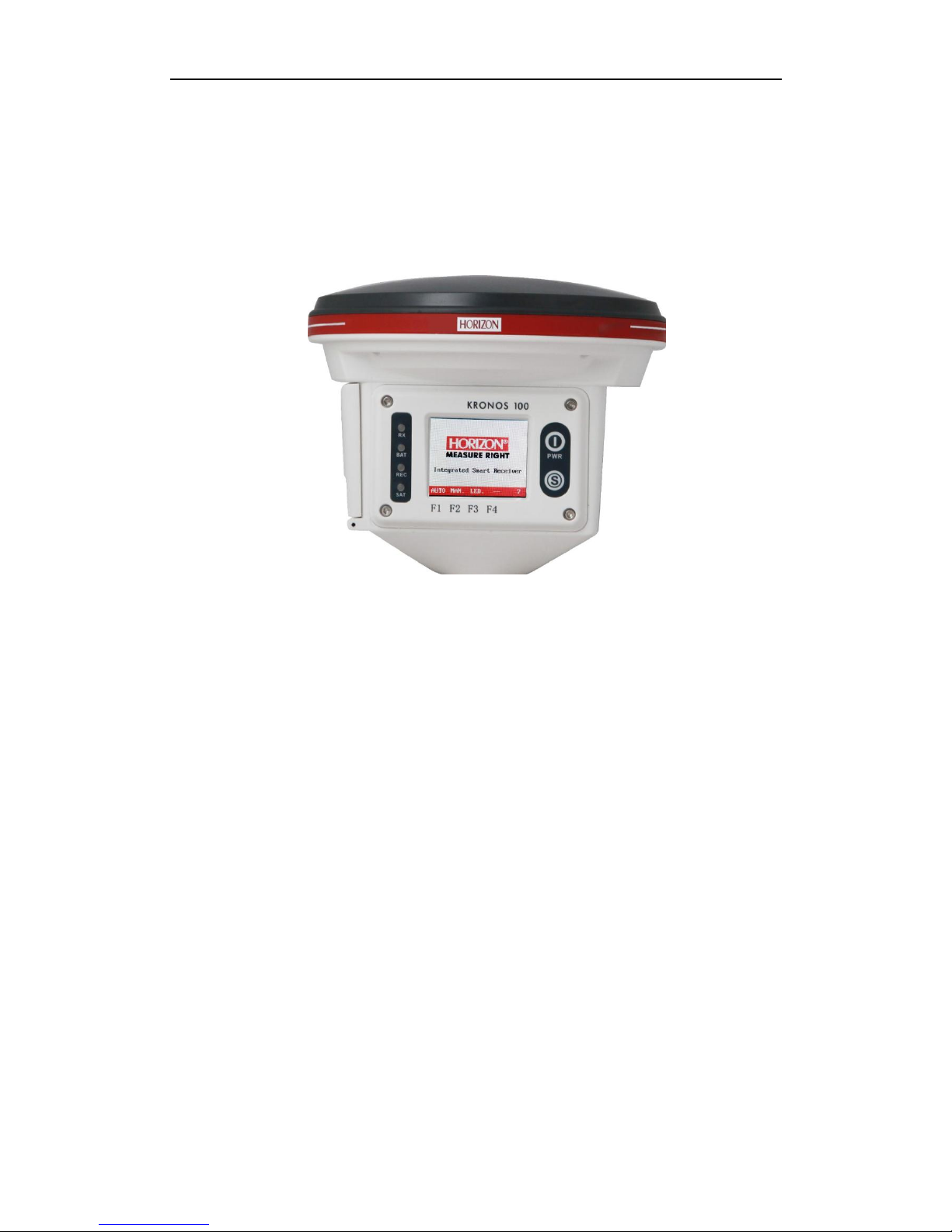
1.2.1Controller
This controller has 16 keys. Number keys from 0-9. There are four function keys: F1, F2,
F3 and F4. The other two keys, Fa and Fb, currently not in use.
Page 5
5
Figure 1-2 Controller
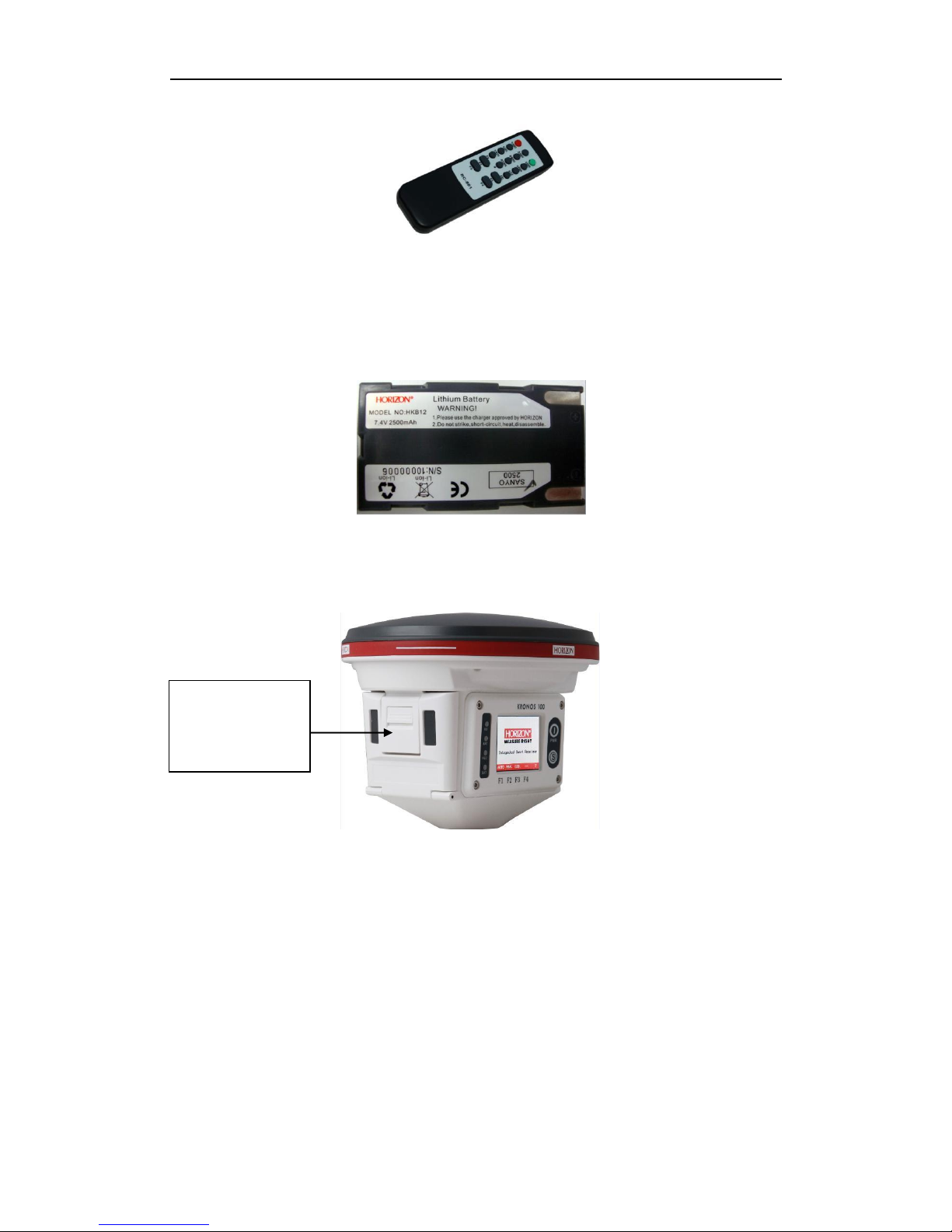
1.2.2 Battery and Charger
A. Battery
The receiver uses rechargeable lithium batteries. It can last 7.5 hours continuously and
needs five hours to recharge.
Figure1-3 lithium-battery
Installing the battery
1. Open the cover of batteries slot, see the following figure:
Figure 1-4 open the cover
2. Install the batteries, see figure 1-4.
Please push this
button towards to
bottom
Page 6
6
Figure 1-5 The Battery compartment
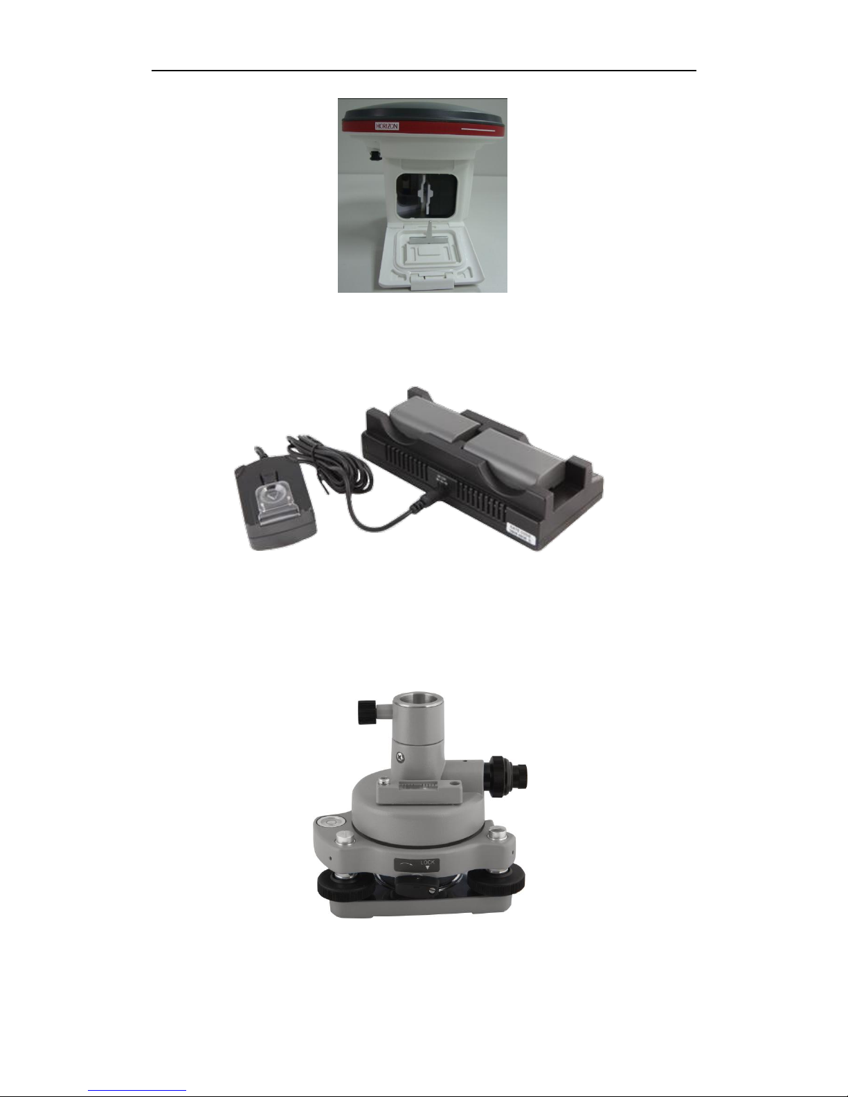
Battery Charger
When recharging battery, the LED will display red. When batteries are fully charged, the LED
will display green. If the charger does not connect with battery, the LED is also red.
Figure 1-5 Chargers
1.2.3 Tribrach & plummet
KRONOS100 GPS receiver uses standard optical tribrach & plummet
Figure1-6 tribrach &plummet
Page 7
7
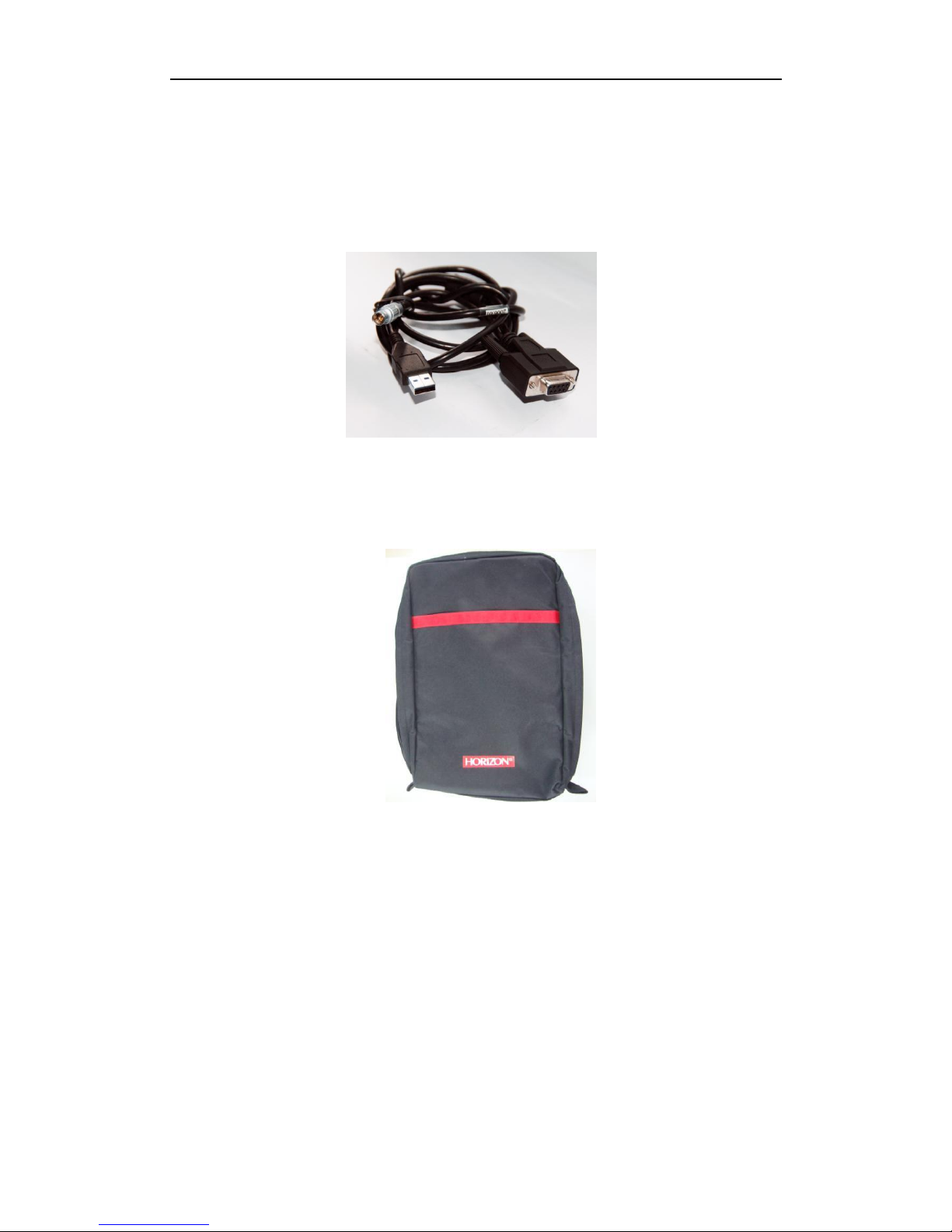
1.2.4 Communication cable
KRONOS100 receiver uses a USB cable to connect to PC. One end has 7pins, and there are
two connectors on the other end, a COM connector and a USB connector. The USB port is
used to connect receiver to PC, and download data from receiver. The COM port is used to
upgrade firmware for the receiver.
Figure 1-7 communication cable
1.2.5 Soft bag
KRONOS100 soft bag is a durable soft casing to carry and store the KRONOS 100 receiver.
Figure 1-8 Soft bag
1.3 Software of KRONOS100 GNSS Survey System
A. Firmware software
This is the firmware software, used to record raw data in the field.
B. Downloading software (KRONOS STATIC MANAGER)
It is used to download data from receiver to computer and to register code for receiver.
C. Post-processing software
This software is used to process and adjust the raw data recorded in receiver.
Page 8
8
Figure 1-9 post processing software
Page 9

9
Chapter II Preparing work
2.1 Working mode of KRONOS100 receiver
GPS working mode is the working measure adopted to ensure the relative position between
observation stations by use of GPS orientation technology. Different working mode has
different working measure and different time interval of observation. KRONOS100 GPS
surveying system is mainly used in control survey, which adopts static carrier wave relative
orientation mode.
2.2 Graph design of net
The net design mainly subject to the users’ requirement, but outlay, time interval of
observation, type of receiver and the receiver amount, etc also relate to the net design.
In order to satisfy the users’ requirement, we should keep the principle as follows:
1. GPS net normally forms closed graph by independent observation borders, such as triangle,
polygon or connecting traverse, etc, to add checking conditions and to improve the net
consistency.
2. When designing the net, the net point should be superposition with the original ground
net points. The superposition points are generally no less than three and distribute evenly
on the net in order to ensure the changing parameters between GPS net and local net.
3. GPS net point should be superposition with the level points, and the other points are
normally united—surveyed with level surveying way or the equivalent way. You can also set
some level united—surveying points in order to offer geoid’s information.
4. In order to observe and level united survey, we often set GPS net points at a clear and easy
arriving field.
5. We often distribute some well eyeshot azimuth points around GPS net to ensure united
survey direction. The distance from azimuth to observation station should be more than 300
meters.
According to different purpose of GPS surveying, independent observation borders of GPS
net should compose definite geometry graph. The basic graphs are as follows:
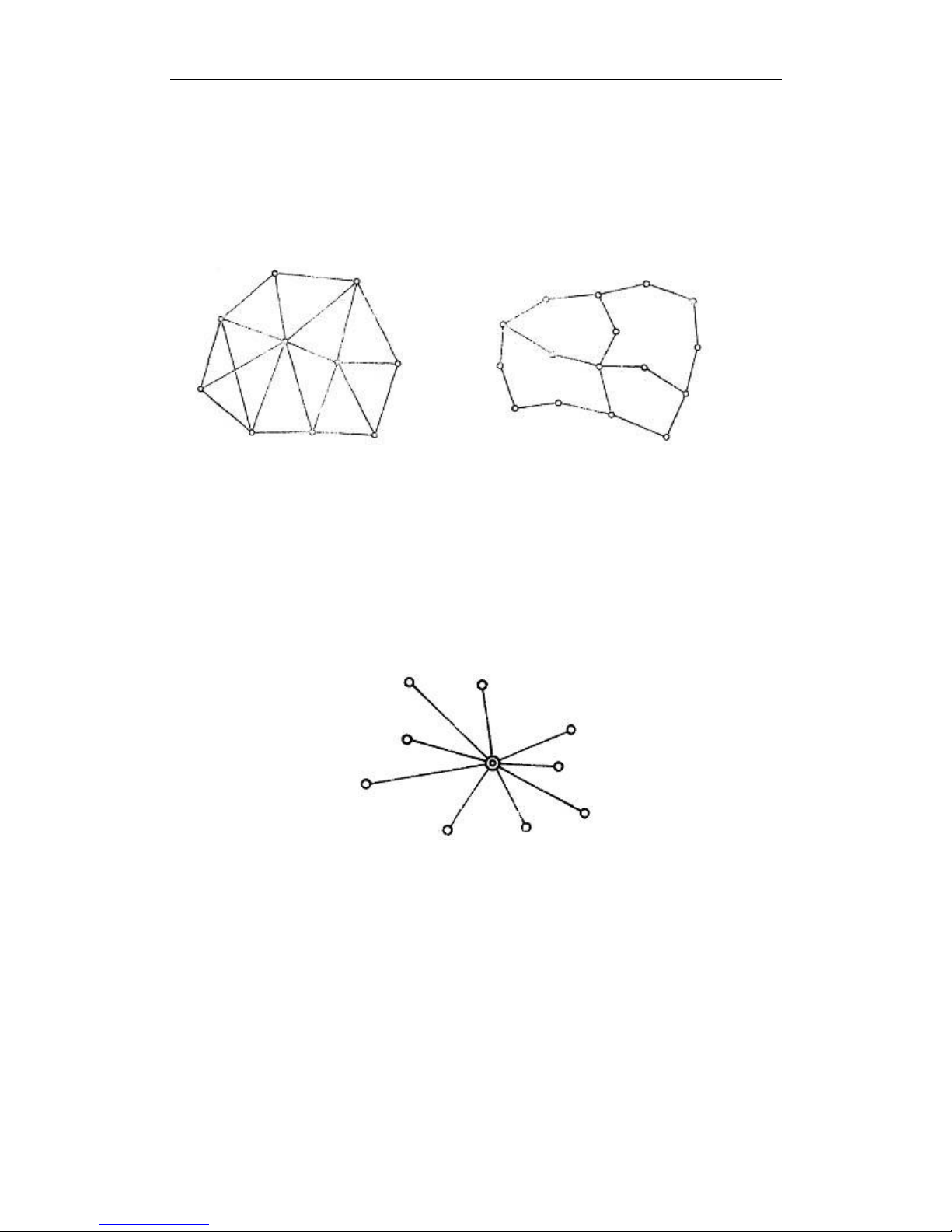
1. Triangle net
The triangle in GPS net is composed of independent observation borders, it has strong
geometry structure and well self-checking ability, it can also find out the coarse difference of
result and to share the difference to each KRONOS100line with adjustment.
But this net need a lot of observation, especially when receivers are lacking it will greatly
prolong the observation time. So only when accuracy and security are required very high,
and receivers are more than three, we can use this graph, see fig 2-2.
2. Circle net
Circle net is composed of many loops which are formed of many independent observation
borders. This net is similar with one of the classical surveying-- lead net. Its structure is a
little worse than triangle net. The amount of KRONOS100 lines in closed loop decides the
self--checking ability and consistency. General speaking, the amount of KRONOS100 lines
has such limit as follows:
Page 10
10
The advantage of circle net is the small workload, good self-checking and consistency. But
the main disadvantage is that the accuracy of indirect-observed border is lower than that of
direct-observed border, and the KRONOS100 line accuracy of neighbor points distributes
unevenly. In field surveying, we usually use annexed traverse as special example according
to practical situation and the net usage. This requirement for this traverse is the high
accuracy for the known vectors between two point ends. Furthermore, the amount of
annexed traverses cannot exceed the limits.
Fig 2-1 triangle net Fig 2-2 circle net
3. Star shape net
Star net has simple geometry graph, but the KRONOS100lines of it mostly don’t compose a
closed graph, so it has a bad checking ability and consistency.
The advantage of this net is that it only needs two receivers, the work is very simple, so it is
mostly used in the quick surveying as quick static orientation and kinematical orientation.
This working mode is widely used in project layout, border surveying and GIS surveying, etc.
Figure 2-4 star net
2.3 Working range
The accuracy of satellite signal received with GPS receiver can reach millimeter level, but
due to the signal suffers ionosphere and troposphere infection when transmitting through
aerosphere, the accuracy will be depressed. To settle this problem, we adopt adjustment by
use of two receivers to observe one KRONOS100line at the same time, thus the influence of
ionosphere on observation can be mostly counteracted. The shorter of KRONOS100line, the
better is the effect, so we suggest KRONOS100line is not more than 20 kilometers when
designing.
Page 11
11
2.4 Fix the receiver in the field
Steps of fixed receiver:
1. You can mount a tripod on a selected point. Please make sure the surrounding meet
these conditions: avoid under shade and building, keep away from reflecting things and
electromagnetism interfering, etc.
2. Open the instrument case firstly; then take out plummet and the tribrach and mount on
the tripod, center and level the plummet & tribrach on the surveying point.
3. Take out receiver, fix it on the plummet & tribrach and lock it tightly.
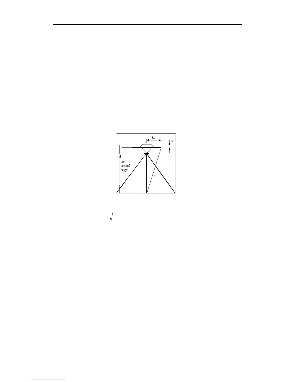
2.5 How to measure antenna height
After fixed the instrument, user should measure antenna height at the beginning and the
end of every period of time to ensure the accuracy “mm” level. We usually measure from the
center point on the ground to the center waterproof loop of antenna. That is an inclined
height. Please refer to fig 2-5.
Fig2-5 Measuring antenna height
We use a formula to calculate antenna height.
H h R h
202
0
(2-3)
“h” is the inclined height that measure from point on the ground to the waterproof loop of
antenna.
R
0
is the radius of antenna.
h
0
is the distance from antenna phase center to the middle of antenna.
H is the calculation result. We usually measure antenna height twice and adopt the
average.
Attention: We input the inclined height as the antenna height, which is the inclined
distance from point on the ground to the waterproof loop of antenna.
2.6 Notice of using KRONOS100 receiver
When you use KRONOS100 receiver, please pay attention to the following items.
1. You must operate according to this manual to ensure the required result. For example,
when you select surveying point, you should avoid shade, buildings, interfere fountain and so
on.
2. The receiver should not work under low power; otherwise, the data quality cannot be
Page 12

12
ensured.
3. When conveyed the mainframe, please be careful.
4. Please ensure that receiver should be used once every three month. Otherwise, the data
stored in the EMS will be lost, and when you use the receiver next time, the receiver will
take a long time to initialize .
Page 13

13
Chapter III Operation in the field
Connecting controller with receiver
The first time you want to connect controller with mainframe, you can press S key quickly,
then press any button on controller, it will build connection between receiver and controller.
If you want to clear the connection, you can press and hold S key.
3.1 main interface
3.1.1 Initialize interface
Power on KRONOS100 receiver, you will see the initialization interface as following:
F1 F2 F3 F4
Figure 3-1 Vector KRONOS100 Initialization interface
1. Mode select in initialization interface
There are three modes in the initialization interface, which are AUTO, MAN and LED., with
the default being AUTO mode.
a. AUTO mode
It is a very intelligent collecting mode, the receiver can evaluate if the condition meets the
requirement and then auto enter the collection status. At the same time, you can see satellite
ephemeris and distribution.
b. MAN mode
This mode needs you to estimate if the collecting condition meets the requirement, which
asks for PDOP less than 6 and in the 3D status, you can input point name and period of time
number to enter the collecting state.
c. LED mode
At this state the LCD doesn’t work, you can only estimate the collection state according to
indicator lights.
2. Indicator lights
On the left of LCD screen, there are four indicator lights, which are RX light, battery
light ,recording light and satellite indicatory light from top to bottom.
If two batteries are both not enough, the power light will blink.
When it enters 3D, receiver will log data, the recording light will blink as time interval.
3.1.2 System interface
Select AUTO or MAN. to enter main interface. See figure as follows.
Page 14

14
F1 F2 F3 F4
Fig 3-2 main interface of file system
The main interface includes three parts.
a. Satellite distributing graph
You can see how many satellites can be observed from this graph.
b. System prompt area
LSTIME: it shows local time.
RETIME: it shows that receiver logged time.
FREEMEM: it shows you the free memory of the receiver. For example, on the screen you
can see 16048K, which means the rest EMS memory is about15.6M. Power system and
battery showing:It shows that how much power is used.
c. Function key
If you want to use function key, please select the key on the controller. For example, select F1
to enter the “File” menu.
The introduction of every function key is as follows.
1. Press F1 to enter “file” interface, see fig 3-3
F1 F2 F3 F4
Fig 3-3 second interface of file
You can view the data storage state in the file interface.
If you select MAN., you will see point names on the screen.
Press F1, to enter next page.
Press F2, to enter previous page.
Page 15

15
Press F3, to select a file in the current page.
Press F4, to return main interface.
2. Press F2 to enter “set” interface, see fig 3-4.
F1 F2 F3 F4
Fig 3-4 second interface of “set”
Press F1 to set the collecting interval, the default value is 10 second. You can press F1 to
change the interval. Press F2 to change the mask angle, you can change it from 0 degree to
45degrees. Press F3 to change the track times, which is used for Stop and go function.
After you finish all settings, press F4 to confirm, the setting will be saved.
Special notice: If several receivers are working at the same time, please set their mask angle
and collecting interval as the same.
3. Press F3 to enter “survey” interface, see fig 3-5.
F1 F2 F3 F4
Fig 3-5 second interfaces of “measure”
It includes five submenus: status, satellite, point name (collection), return and icon logging.
Press F1 to show LONG., LAT., ALT., PDOP, NAV. MODE, FIXED and number of visible satellite,
see figure 3-6.
Page 16

16
F1 F2 F3 F4
Fig 3-6 second interfaces of “status”
Press F2, it will show ID of satellites and SN, see fig 3-7.
Press F3 in the AUTO mode, it will show point name. In the MAN mode, it will show
collection,see fig 3-8.
You can input the information of point in the fig 3-8, such as name of point, number of time
period of collection and antenna height.
Point name: please input four characters. the name should be as four characters.
Number of period of time: this is to select the surveying period for control point, it requires
to input the same file name and different period number before you move the control point.
Antenna height: the height of receiver. The method is to survey from point on the ground to
the blue seal waterproof loop.
F1 F2 F3 F4
Fig 3-7 second interface of “satellites”
Page 17

17
F1 F2 F3 F4
Fig 3-8 input point information
Introduction of input method:
Press F1 to select a character among character segment.
F2 key is used to move cursor.
Press F3 continuously to select different characters segments, such as 0-9, A-G, H-N, O-U, V-Z.
Let’s use GPS1 as the point name to introduce:
(1). Select the characters segment from A to G with key F3.
(2). Use F1 to select the letter G from the above characters segment, thus character G is
inputted.
(3). Use key F2 to move the cursor..
(4). Repeat the steps until input the whole name “GPS1”.
(5). Press F4 to finish this operation.
When the cursor moves to “period of time input” and “antenna height input”, input them
according to the way above, press F4 to confirm it and return to the main interface.
4. Press F4 to enter “system” interface, see fig 3-9
F1 F2 F3 F4
Fig 3-9 system
Page 18

18
F1 key: switch LED or not
F2 key: power off
F3 key: the information of the firmware.
5. Long press PWR turn off the receiver.
3.2 Operation in the field
Power on KRONOS100 receiver, there are three collecting modes in the initialization
interface, You need to select one of them within ten seconds, otherwise, the system will
enter “Auto Mode” automatically.
3.2.1 AUTO Mode
1. Data collecting
Press F1 to enter AUTO mode, see fig 3-10.
F1 F2 F3 F4
Fig 3-10 automatic interface
Enter AUTO mode, software will auto estimate the orientation status and the PDOP value.
You do not need make any operation; the software will enter the data collect status when
PDOP meets the requirement. You can see the increasing time in the right side, which means
KRONOS100 mainframe is logging the GPS data. You can name the logging data or the
software will set the default name as “****”. The file construction is set according to collecting
turns, if you want to reset the file name, please change it when logging the data, you can also
rename it according to the operation below:
2. Name a file for the saved data:
a. Press F3 to enter “survey” interface, you can see the single point geodetic coordinates,
receiver status, positioning status and PDOP.
Page 19

19
F1 F2 F3 F4
Fig 3-11 “survey” interface
b. Press F3 to enter point name input interface, you can name the logging data, input period
number and antenna height here, see as:
F1 F2 F3 F4
Fig 3-12 name interface
Note: The different between AUTO and MAN: In AUTO mode, the receiver names the data
when logging it, but in MAN mode, you should input the point name and press the key to
start log date.
3. End logging data:
Firstly, you should end to log the data, before you power off the receiver. Please refer to
figure 3-11, when the time is enough, you can press “F4” to end logging.
4. Power off receiver.
1). Use controller to operate the receiver back to the main interface and long press PWR key
on receiver to turn it off.
2). Switch to the interface as following figure, then press F2 to power off receiver.
Page 20

20
F1 F2 F3 F4
Figure 3-13 power off receiver
2.2.2 MAN. Mode Collecting
1. Data collect
Power on receiver, enter MAN mode by pressing F2 key in the initialization, see fig 3-14.
In this mode, the receiver will not auto collects data until you confirm that the receiver status
meets the required condition, which is PDOP less than 6 and in 3D status. When conditions
are satisfied, press F3 to enter data collecting interface, see fig 3-15.
2. Name a logging file:
When conditions are satisfied, press F3 to enter file name input interface, see fig 3-12. When
you finish the input of file name, number of period of time and antenna height, press F3, the
receiver will begin to log data.
Page 21

21
3. Exit data logging: The operation is the same with “AUTO” mode.
F1 F2 F3 F4
Fig 3-14 manual interface
F1 F2 F3 F4
Fig 3-15 measure interface
Page 22

22
2.2.3 LED mode
1. Data collect
Turn on the receiver, press F3 to enter LED mode
The operation in this mode is very simple. When you enter this mode, the LCD screen will
auto shut off, you can only view the satellite and collecting status according to the LED, see
fig 3-16.
Fig 3-16 mainframe
The instruction of indicator LED can be found in 3.1.1. In the LED mode, you can press any
key to activate display screen and enter AUTO mode.
Page 23

23
Chapter IV KRONOS100 Differential GPS System
The function of KRONOS100 differential GPS system is KRONOS100-differential on Static
GPS KRONOS100. It adopts differential method.
4.1 Working Mode
Set up a KRONOS100 receiver as the station to log static data. Take the other KRONOS100
receiver as a Rover moving among the requested points. During moving, it will record data
according to the collection interval which is set before. The receiver must receive not less
than four satellites at the same time and the signal tracked must be continuous. More than
one epoch interval (1-255second optional,Default:5s) must be observed at one point, and
the survey process of “GO AND STOP” is finished here.
After working in the field, you should download the data from receiver to PC. Then use
KRONOS PROCESSOR, after processing, the coordinates result will be output directly and all
the tracking line will be displayed.
Operation range: <= 100km Positioning accuracy: < 1m
4.2 The Initialization Interface
Press Power key, power on receiver. The interface is shown as figure
F1 F2 F3 F4
Fig 4-1 Post-differential opening interface
4.3 Steps of Field Work
Step 1: set up KRONOS100 station
All operations are the same as KRONOS100 receiver, such as following figure.
F1 F2 F3 F4
Fig 4-2 differential survey main interface
There are three optional modes to enter KRONOS100 data-collecting status. They are AUTO,
Page 24

24
MAN and LED. The detailed operations please refer to chapter three of ‘KRONOS100 survey
system’.
After the KRONOS100 enters the data collection status shown as figure 4-3, the
KRONOS100-Rover can enter the surveying area to do differential survey.
F1 F2 F3 F4
Fig 4-3 KRONOS100 data collection interface
Steps 2: KRONOS100 ROVER data-collection
Note: Ensure that both KRONOS100-Rover and KRONOS100-Base collect data at the
synchronization. Only after the KRONOS100-Base enters data collection status,
KRONOS100-Rover can begin to collect data in the survey area.
Select tracking mode on the initial interface (Fig 4-1,press F4) to enter KRONOS100-Rover
data collection status.
F1 F2 F3 F4
Fig 4-4 KRONOS100-Rover setting interface
Functions of keys:
[F1]: To set collection interval time.
The default interval is 5 seconds, means the epoch of record is 5 seconds.
[F2]: To set mask angle.
The default mask angle is 10 degrees. Press F1 continuously, the mask angle can be changed
from 0 degree to 45 degrees.
[F3]: To set the times of collection points.
It means that at one point, the receiver will record 3 times raw date. For example, if you set
Page 25

25
collecting interval to be 5 sec and set the times of collection points to be 3 times, it need a
surveying time of 15sec on every point.
How to set the KRONOS100-Rover in the field? Please refer to the following steps:
1. On the initial interface(Fig4-1), press F4 to select “TRK” mode, it will enter collection
interface shown as figure 4-2.
2. Press F2 [SET], shown as following, set the interval time , mask angle and track time,
then Press F4[OK] to return the former interface (figure 4-2)
F1 F2 F3 F4
Fig 4-5 setting interface
3. When the condition is satisfied, please press F3 [MEAS], shown as following picture you
will see some information. Such as satellite, PDOP value, and so on.
F1 F2 F3 F4
Fig4-6 Status interface
Note: the collection condition is satisfied means position status is 3D, PDOP is less than 6.0 and
locked satellites are more than 4.
Page 26

26
F1 F2 F3 F4
Fig4-5 collection interface
4. Press F3 [TRK] , select TRK mode, it will pop the picture 4-7, input FILE NAME and
TRAGET HT.
F1 F2 F3 F4
Fig4-7 point setting interface
5. After setting point name and height, press F3 to enter track interface, shown as Fig4-8.
Check the satellite status, such as Nav mode, PDOP etc.
F1 F2 F3 F4
Fig 4-8 Track interface
Page 27

27
6. After check, Press F1 [SAMP] to collecdata, see the picture as following:
Fig 4-9 Surveying interface
After complete, you can hear a long beep, and the STATUS become SAMPLE 06/06. Then
take the KRONOS100-Rover to go another target to survey and follow the 5 and 6 steps
above.(In same surveying area, no need to move the KRONOS100-Base).
Special Tip:
1. For ensuring survey accuracy, please make sure receiver is fixed when initializing, and
please make sure your pole is level when collecting. Don’t shake the mainframe.
2. Please note the value of cycle slip on the interface when colleting. If the value of cycle slip
is too big (more than 07), it should be initialized again.
Page 28

28
4.4 Dynamic post-processing software
4.4.1 Software start-up & operation brief
1. main features of software includes:
English Windows interface
Edit function: switch the format of file data, output the coordinates report( requires to
input the meridian and one known point within coverage), define the coordinate
system ( parameter of ellipsoid and Meridian)
Compatible with CAD, calculation including sides and area.
Easy-operation only needs three steps:
Step 1: Add KRONOS100 base data and KRONOS100 rover data
Step 2: Input the local parameter and the known point restriction post-processing
Step 3: Edit and print report
Output the coordinate file documents directly
The coordinate data can be switched its format to imported into GIS as geography data
Compiled by Visual C++, which calculates at a high speed.
2. Software use introduction
Basic steps:
New job
Fill in each item in the dialog box, especially must select the coordinate system and
projection zone
Add observation data
Import the KRONOS100 Base and Rover data of *.DAT to the software at the same time
Post differential processing
Input the known coordinate value of Base, get the report after real-time processing
Report output
The purpose of this step is to import the report into other software, such as CAD, MAPINFO
and so on, in order to proceed more convenient editing and mapping.
4.4.2 Main menu & function introduction
1. Functions of the software
The software using differential GPS collecting data, adopts the pseudo-range differential
principle to calculate the position coordinate of the discrete points and close the coverage in
order to calculate the area of the coverage.
2. Main menu and function introduction
1. Post differential processing
Processing menu
Fig 4-10 Post differential menu
Page 29

29
Processing setting: set the relevant parameter for data processing. Click button “Solve
setting”, a dialog box comes up as Fig 4-11
Fig 4-11 Differential processing setting
Record: Usually adopt default
Output setting: set the display of output figures and files. Click “Report settings” from menu
and there is a dialog box coming up.
Fig 4-12 Differential output setting
Tracking: process the collected data using differential mode
Calculate the four parameters: calculate the four parameters by two points, then import the
parameter setting to use in the processing.
3. Software use model
This chapter use example data to introduce the specific operation.
Before use this software, it requires to get a register No., the way of registration is the same
as static processing software.
Both Base file 8464273D.DAT of field surveying data and Rover file 84712739.DAT are as
demo data. What need to be emphasis is that these two files must be the synchronous
observation ones.
1. New job
Click “ New” from menu, comes out a form, fill in the following items according to the true:
Page 30

30
Fig 4-13 New Job
If there is a job file existing, close this existing file, then create a new job. After filling all the
items, click “OK” to enter program.
2. Add observation files
The input method of Differential data is the same as static. Click “ Add GPS observation file”
from “ Input”,or after adding observation file shortcut key, select the observation data from
the coming out file-select dialog box, click “ OK” to complete the import work. The demo data
of the software defaults the path “C:\Program Files\KRONOS\KRONOS
PROCESSOR\Example\TRACK”. Here select the collected file 8464273D.DAT and
84712739.DAT as example, data information is visible from the form of “ Observation data ”
when the file is imported. Please refer to the following figure 4-14:
Fig 4-14 Differential data
From the above figure, the data has been imported into the program.
3. Input the known coordinate of KRONOS100 Base station
Click “ Station coordinate” from “Input” menu, and a dialog box comes out, shown as below:
Fig 4-15 Input known coordinate
The default coordinate value of the software is the single point geodetic coordinate set in the
“ Project Setting”, but what we usually need is the right-angle coordinate value, so input the
known right-angle coordinate value of the KRONOS100 in the coming out dialog box.
Note: Not only requires to input the plane right-angle coordinate, but also the Height value
while setting the KRONOS100 base coordinate
4. Differential processing and output network report
Click “ tracking” from ”Track” menu or click the Post differential processing shortcut key,
and the software will process the data automatically, showing the report as the following
figure:
Page 31

31
Fig 3-16 Differential Processing Report
Click the status bar on right to show the network as the following figure
The coordinate value and network graph of the surveying point are available here, which can
be printed on the current form. If want to make further use of the report, export the report
in the format of file, in order to import the surveying data into other software.
Select “ Track report” from “ Report”, coming out a dialog box.
Select an output path for the report file. You can select different output result from this
menu.
Page 32

32
Chapter V Manual of KRONOS STATIC MANAGER
5.1 Brief introduction
The The interface is as follows:
This software can be used to download raw data. Device setting , Register and Firmware
upgrade for KRONOS100.
Note:Before connect KRONOS100 with PC via USB, power off KRONOS100
first .(5.1.1-----5.1.3)
5.1.1 Import record data
After connect well, open the receiver disk, you will see the DAT file
Page 33

33
Select the file you want to download, and change the parameters in the KRONOS
PROCESSOR.
5.1.2 Device Setting
Click "Device Setting", then it will pop windows as following:
Interval: recording interval for data.
Cut angle: mask angle for tracking satellites.
Time zone: local time zone.
Sample time: recording times for one point.
5.1.3 Register
In the main interface, click "Register"
Page 34

34
Then Click "change" to input new register code,
Click "Enter" to input
Click "Yes", then click "Save" to finish.
Page 35

35
5.1.4 Firmware Upgrade
First connect KRONOS100 with PC via serial port, click "firmware upgrade" in the main
interface
Then power on KRONOS100, select right COM port and click "open", it will pop a windows ,
you need find the new firmware where it is.
Page 36

36
Click ''open"
It need restart KRONOS100 during 20 seconds.
After restart, it start to upgrade:
Page 37

37
Wait a moment , after finish you will hear a beep.
Page 38

38
Appendices
A Specification
1. Receiver:
Channel: independent 12 channels
Tracking signal: L1, C/A code
Memory: 4G
Working time: two batteries last 16 hours
Epoch interval:1 second—60 second
Phase center: on the center point of receiver top
Operation environment temperature:-40~+70℃
Storage environment temperature: -50~+80℃
Power input: 6V~10V DC
Power: ≤1.5 W
Weight of mainframe: 0.6 Kg
Data transmit: High Speed USB
Azimuth:0-45
Initial collect satellite: ≤60 seconds
Dustproof, sand-proof
2. Static accuracy:
Static horizontal accuracy: 5mm±1ppm
Static vertical accuracy: 10mm±1ppm
Single orientation accuracy:>5m
Operation Distance: ≤30 km
Page 39

39
B Standard Packing
Please check your packing refer to the following list when purchasing:
Item
Amount
Type
mainframe
1
Standard
configuration
Lithium battery
2
Lithium battery charger
1
Tribrach and plummet
1
Controller
1
Communication cable
1
Connector
1
Pocket tape
1
Carrying case (soft bag)
1
Software CD
1
 Loading...