

Page 1
1
Page 2

CONTENTS
1. PREPARATION…………………………………………………………1
1.1 Precaution……………………………………………………………1
1.2 Nomenclature…………………………………………………………3
1.3 Unpacking and Storing of the Instrument……………………………5
1.4 Setting Up the Instrument …………………………………………5
1.5 Battery Removal & Insertion, Information and Recharging ………7
1.6 Reflector Prisms……………………………………………………9
1.7 Mounting and Dismounting Instrument from the Tribrach…………10
1.8 Eyepiece Adjustment and Object Sighting…………………………11
1.9 Turning On and Off………………………………………………11
1.10 How To Enter Alphanumeric Characters…………………………12
2. FUNCTION KEY AND DISPLAY……………………………………14
2.1 Operating Key……………………………………………………14
2.2 Function Key………………………………………………………16
2.3 Star-key Mode……………………………………………………19
2.4 Dot-key Mode……………………………………………………20
3. INITIAL SETTINGS…………………………………………………21
3.1 Setting of the Temperature and Air Pressure………………………21
3.2 Setting of the Atmospheric Correction……………………………22
3.3 Setting of the Prism Constant ……………………………………24
3.4 Setting of the Vertical Angle Tilt Correction………………………25
4. ANGLE MEASUREMENT……………………………………………26
4.1 Measuring Horizontal Angles Right and Vertical Angle……………26
4.2 Switching Horizontal Angle Right/Left……………………………28
4.3 Setting of the Horizontal Angle….………………………………29
2
Page 3

4.3.1 Setting by Holding the Angle………………………………29
4.3.2 Setting the Horizontal Angle from the Keypad………30
4.4 Vertical Angle Grade Percentage (%) Mode………………………31
4.5 Setting the Initial Zenith Angle…………………………………32
5. DISTANCE MEASUREMENT………………………………………33
5.1 Setting the Atmospheric Correction………………………………33
5.2 Setting the Prism Constant………………………………………33
5.3 Distance Measurement (Continuous Measurement)………………33
5.4 Changing the Distance Measurement Modes……
……………………
35
(repeat measurement / single measurement / track measurement)…35
5.5 Stake Out (S.O.)……………………………………………………36
5.6 Offset Measurement………………………………………………38
5.6.1 Angle Offset………………………………………………38
5.6.2 Distance Offset Measurement……………………………41
5.6.3 Plane Offset Measurement…………………………………43
5.6.4 Column Offset Measurement………………………………46
6. COORDINATE MEASUREMENT……………………………………49
6.1 Execution of Coordinate Measurement……………………………49
6.2 Setting the Coordinate Values of an Occupied Point……………51
6.3 Setting the Height of the Instrument……………………………53
6.4 Setting the Height of the Target (Prism Height)…………………54
7. SURVEYING PROGRAMS…………………………………………55
7.1 Remote Elevation Measurement (REM)…………………………55
7.2 Missing Line Measurement (MLM)……………………………59
7.3 Area Calculation………………………………………………65
7.4 Setting Z (elevation) Coordinate of an Occupied Point…………69
7.5 Point to Line Measurement……………………………………73
7.6 Road Measuring……………………………………………………77
3
Page 4

7.6.1 Designing Horizontal Alignment Projects………………77
7.6.2 Editing Horizontal Alignment Data………………………86
7.6.3 Importing Horizontal Alignment Data……………………88
7.6.4 Deleting Horizontal Alignment Data………………………91
7.6.5 Designing Vertical Curves…………………………………91
7.6.6 Editing Vertical Alignment Data…………………………94
7.6.7 Importing Vertical Alignment Data…………………………95
7.6.8 Deleting Vertical Alignment Data…………………………96
7.6.9 Generating a Road Coordinate File………………………97
7.6.10 Road Setting Out………………………………………97
7.6.11 Slope Setting Out………………………………………105
7.7 Layout ……………………………………………………………107
7.8 Resection…………………………………………………………107
7.9 Volume Calculation…………………………………………………108
7.10 Traverse Adjustment………………………………………………109
7.11 COGO…………………………………………………………115
7.11.1 Inverse Calculation ………………………………………115
7.11.2 Traverse Calculation………………………………………116
7.11.3 Intersection………………………………………………118
7.11.4 Calculating the bias point…………………………………121
7.11.5 Calculating the pedal………………………………………123
8. DATA COLLECTION…………………………………………………126
8.1 Operation procedure ………………………………………………127
8.2 Preparation…………………………………………………………128
8.2.1 Selecting a File for Data Collection…………………………128
8.2.2 Selecting a Coordinate File ………………………………129
8.2.3 Occupied Point and Backsight Point………………………130
8.2.4 Measuring and Memorizing the Data………………………135
4
Page 5

8.3 Data Collect Offset Measurement Mode…………………………140
8.3.1 Angle Offset………………………………………………140
8.3.2 Distance Offset Measurement……………………………143
8.3.3 Plane Offset Measurement…………………………………145
8.3.4 Column Offset Measurement………………………………148
8.4 Editing the PCODE Library [PCODE INPUT]………………………151
8.5 Setting the Parameters for Data Collection…………………………153
9. LAYOUT…………………………………………………………………154
9.1 Setting the Parameters for Data Collection………………………155
9.2 Preparation…………………………………………………………155
9.2.1 Setting the GRID FACTOR…………………………………155
9.2.2 Selecting the Coordinate Data File…………………………155
9.2.3 Setting the Occupied Point…………………………………157
9.2.4 Setting the Backsight Point…………………………………159
9.3 Executing a Layout…………………………………………………162
9.4 Setting a New Point…………………………………………………165
9.4.1 Side Shot Method……………………………………………165
9.4.2 Resection Method……………………………………………168
10. MEMORY MANAGEMENT MODE………………………………174
10.1 Choosing a Storage Medium……………………………………176
10.2 Displaying the Internal Memory Status…………………………177
10.3 Searching Data…………………………………………………177
10.3.1 Measured Data Search…………………………………178
10.3.2 Coordinate Data Search…………………………………181
10.3.3 PCODE LIBRARY Search
…………………………………
182
10.3.4 Plotting Points……………………………………………184
10.4 File Maintenance………………………………………………185
10.4.1 Renaming a File…………………………………………186
5
Page 6

10.4.2 Deleting a File……………………………………………187
10.5 Direct Key Input of Coordinate Data …………………………188
10.6 Deleting Coordinate Data from a File……………………………189
10.7 Editing the PCODE Library……………………………………191
10.8 Data Communication……………………………………………192
10.8.1 Data Communication using RS-232………………………193
10.8.1.1 Sending data……………………………………………194
10.8.1.2 Loading data……………………………………………195
10.8.1.3 Setting the parameters of data communication………197
10.8.2 Data Conversion using USB………………………………199
10.8.2.1 Data export……………………………………………199
10.8.2.2 Data import……………………………………………200
10.9 File Operation……………………………………………………200
10.9.1 Copy a file from the SD card to memory of the instrument…201
10.9.2 Copy a file from current work memory to the SD card…202
10.10 Initialization…………………………………………………………204
11. BASIC SETTINGS…………………………………………………206
11.1 Setting Units……………………………………………………206
11.2 Parameter Settings………………………………………………208
11.2.1 Setting of the Tilt Sensor …………………………………208
11.2.2 Setting of the W-Correction………………………………209
11.2.3 Setting of the Grid Factor…………………………………211
11.2.4 Setting of the Least Angle Display………………………213
11.2.5 Setting of the Vertical Angle Display……………………214
11.2.6 Setting of the plotting points number………………………214
11.2.7 Setting Distance Range Mode…………………………215
11.2.8 Automatic compensation for temperature and air pressure
…………………………………………………………………………216
6
Page 7

11.3 Setting Measuring Mode Display………………………………217
11.4 Setting the Shortcut Keys…………………………………………217
11.5 Other Settings……………………………………………………218
11.5.1 Auto Power Off……………………………………………218
11.5.2 Choosing the Battery Type………………………………219
11.5.3 Reset the Instrument to Factory Settings…………………220
11.5.4 Selecting a Language………………………………………220
11.6 Date and Time……………………………………………………221
11.7 Adjusting the LCD Display Contrast……………………………222
12. CHECK AND ADJUSTMENT………………………………………223
12.1 Plate Vial …………………………………………………………223
12.2 Circular Vial………………………………………………………224
12.3 Inclination of the Reticle…………………………………………225
12.4 Perpendicularity of the Line of Sight to the Horizontal Axis (2c)…226
12.5 Vertical Index Difference Compensation………………………227
12.6 Adjustment of Vertical Index Difference (I angle) and Vertical…228
12.7 Optical Plummet…………………………………………………230
12.8 Laser Plummet (optional)…………………………………………232
12.9 Instrument Constant (K)…………………………………………232
12.10 Parallel check for Line of Sight and Emitting Photoelectric
Axis …………………………………………………………………234
12.11 Tribrach Leveling Screw………………………………………234
13. ERROR DISPLAYS…………………………………………………235
14. SAFETY INSTRUCTIONS…………………………………………237
14.1
14.2 Laser Plummet……………………………………………………239
15. ACCESSORIES………………………………………………………240
Integrated EDM……………………………………………237
7
Page 8

1. PREPARATION
1.1 Precautions
1. Never point the instrument at the sun without a filter.
2. Never store the instrument in extreme temperatures and avoid sudden
changes of temperature.
3. When not using the instrument, place it in the case to avoid shock, dust, and
humidity.
4. If there is a Significant difference in temperature between the work site and
the instrument storage location leave the instrument in the case until it adjusts to the
temperature of the surrounding environment.
5. Please remove the battery for separate storage if the instrument is to be in
storage for an extended time. The battery should be charged once a month during
storage.
6. The instrument should be placed in its carrying case during transportation. It
is recommended that the original packing case be used for cushioning during
extended transportation.
7. Be sure to secure the instrument with one hand when mounting or removing
from the tripod.
8. Clean exposed optical parts with degreased cotton or lens tissue only.
9. Clean the instrument's surface with a woolen cloth when finished with use.
Dry it immediately if it gets wet.
10. Check the battery, functions, and indications of the instrument as well as its
initial setting and correction parameters before operating.
8
Page 9

11. Unless you are a maintenance specialist do not attempt to disassemble the
instrument for any reason. Unauthorized disassembly of the instrument can result in
a void warranty.
12. The HTS580AGX/ARX total stations emit a laser during operation. DO
NOT stare into the beam or laser source when instrument is operation.
9
Page 10
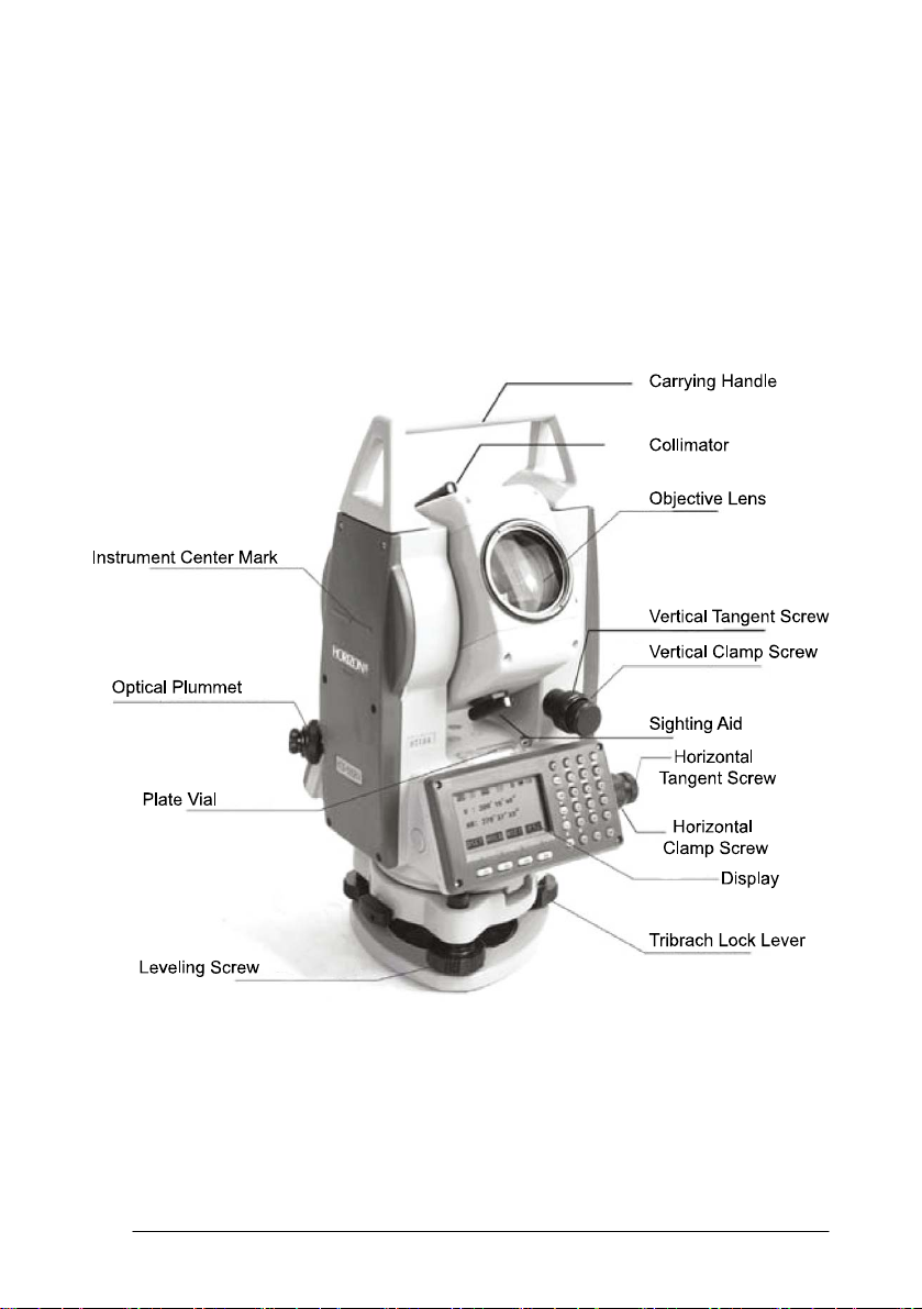
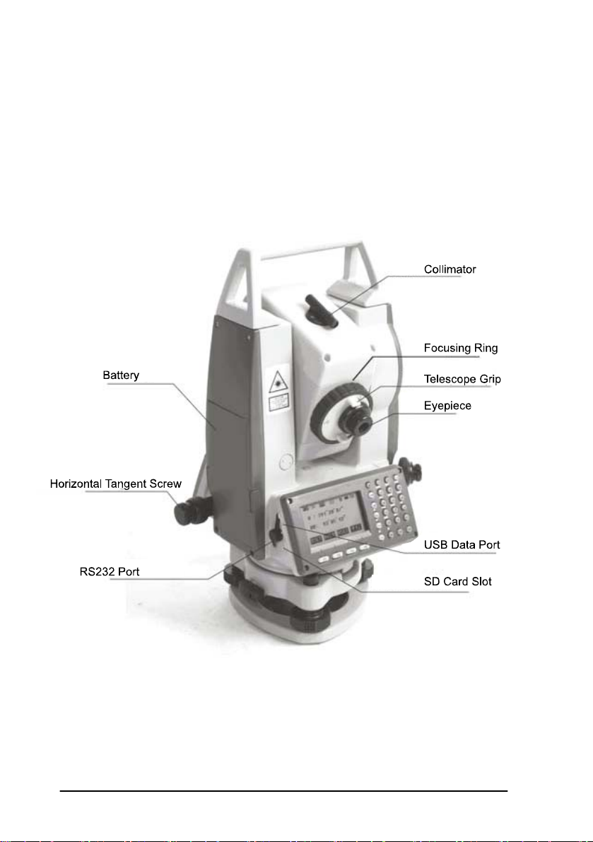
1.2 Nomenclature
10
Page 11
11
Page 12

1.3 Unpacking and Storage of the Instrument
Unpacking of the Instrument
Place the case lightly with the cover upward, unlock the case and take out the
instrument.
Storage of the Instrument
Replace the cover on the telescope lens, place the instrument into the case with
the vertical clamp screw and circular vial upward (objective lens toward the tribrach),
tighten the vertical clamp screw, close and lock the case.
1.4 Instrument Set Up
Mount the instrument onto the tripod and secure firmly. Level and center the
instrument precisely to ensure the best performance. Use a rugged tripod with a 5/8”
tripod screw. Our Fiberglass SL180FGB tripods are recommended.
Operation Reference: Leveling and Centering the Instrument
1). Setting up the tripod
First extend the extension legs to suitable length and tighten the screws, firmly
plant the tripod in the ground over the point of beginning.
2). Attaching the instrument to the tripod
Secure the instrument carefully on the tripod and slide the instrument by
loosening the tripod mounting screw. If the optical plumb site is positioned over the
center of the point tighten the mounting screw.
3). Roughly leveling the instrument by using the circular vial
Turn the leveling screw A and B to move the bubble in the circular vial, in
which case the bubble is located on a line perpendicular to a line running through
12
Page 13

the centers of the two leveling screw being adjusted. Turn the leveling screw C to
move the bubble to the center of the circular vial. Recheck the position of the
instrument over the point and adjust if needed.
4). Leveling by using the plate vial
Rotate the instrument horizontally by loosening the Horizontal Clamp Screw
and place the plate vial parallel with the line connecting leveling screws A and B,
then bring the bubble to the center of the plate vial by turning the leveling screws A
and B.
Rotate the instrument 90° (100g) around its vertical axis and turn the
remaining leveling screw or leveling C to center the bubble once more.
Repeat the procedures for each 90° (100g) rotation of the instrument and
check whether the bubble is correctly centered in all directions.
5). Centering by using the optical plummet(or laser plummet)
Adjust the eyepiece of the optical plummet telescope to your eyesight. Slide the
instrument by loosening the tripod screw; place the point on the center mark of the
optical plummet. Sliding the instrument carefully as to not rotate the axis will allow
you to get the least dislocation of the bubble.(Place star-key after power on, then
press F4(LASER)key, press F1(ON)key to turn on the laser plummet. Slide the
instrument by loosening the tripod screw; Place laser facular on the occupied
pointing, Sliding the instrument carefully as to not rotate the axis will allow you to
get the least dislocation of the bubble. The last, press ESC key, and laser plummet
turn off automatically.)
6). Complete leveling the instrument
Level the instrument precisely as in Step 4. Rotate the instrument and check to
see that the bubble is in the center of the plate level regardless of the telescope
13
Page 14
direction, then tighten the tripod screw firmly.
1.5 Battery Removal & Insertion - Information and
Recharging
Battery removal & insertion
Insert the battery into the battery slot and push the battery until it clicks.
Press the right and left buttons of the battery compartment to remove the
battery.
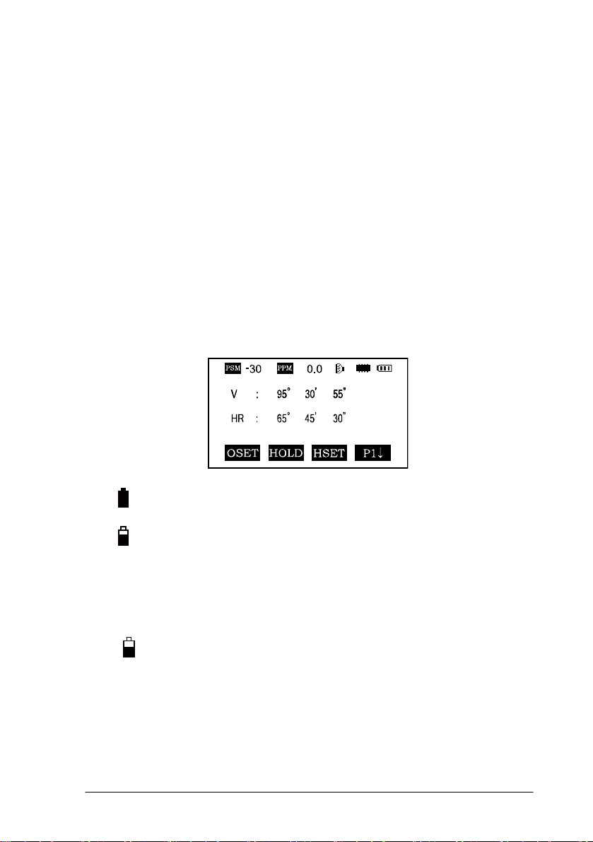
Battery information
------------- Indicates that battery is fully charged
------------- Indicates that the battery can only be used for
about 1 hour.
Recharge the battery or prepare a recharged battery for
use.
------------- Recharge the battery or prepare a recharged
battery for use.
Note: The working time of the battery is determined by environment conditions,
recharging time, and other factors.
Battery Recharging
14
Page 15

Battery should be recharged only with the charger supplied with the instrument.
Remove the on-board battery from instrument as instructed and connect to the
battery charger.
Battery Removal Caution
▲Before you take the battery out of the instrument, make sure that the power is
turned off. Otherwise the instrument can be damaged.
Recharging Caution:
▲The charger has built-in circuitry for protection from overcharging. However,
do not leave the charger plugged into the power outlet after recharging is completed.
▲Be sure to recharge the battery at a temperature of 0℃~45℃, recharging
may be abnormal beyond the specified temperature range.
▲When the indicator LED does not light after connecting the battery and
charger the battery or the charger may be damaged.
Storage Caution:
▲The rechargeable battery can be repeatedly recharged 300-500 times.
Complete discharge of the battery may shorten its service life.
▲In order to get the maximum service life be sure to recharge the battery at
least once a month.
15
Page 16
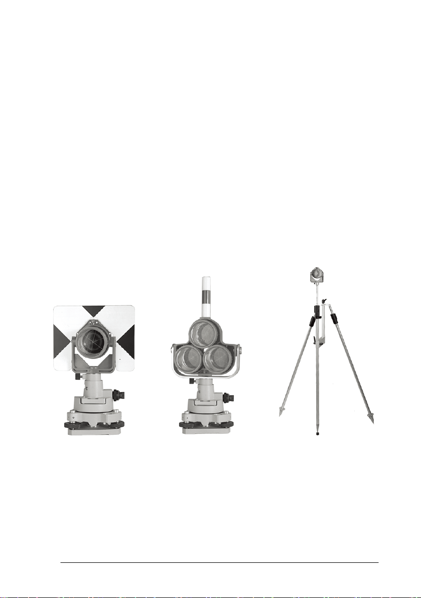
1.6 Reflector Prisms
When doing distance measuring in prism mode a reflector prism needs to be
placed as the target. Reflector systems can be single or multiple prisms which can be
mounted with a tripod/tribrach system or mounted on a prism pole. Unique mini
prism systems allow setups at corners that are hard to reach. Reflectorless targets
extend the range of the instrument when used in reflectorless mode.
Illustrated are some prisms and a reflector compatible with instruments:
16
Page 17
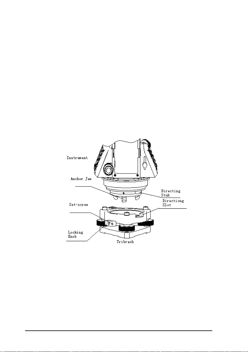
1.7 Mounting and Dismounting the Instrument from the
Tribrach
Dismounting
When necessary the instrument can be dismounted from the tribrach. Loosen
the tribrach locking screw in the locking knob with a screwdriver if necessary. Turn
the locking knob 180 degrees counter-clockwise to disengage anchor jaws and
remove the instrument from the tribrach.
Mounting
Insert three anchor jaws into holes in tribrach and line up the directing stub on
the instrument with the directing slot of the tribrach. Turn the locking knob 180
degrees clockwise and tighten the locking screw with a screwdriver.
17
Page 18

1.8 Eyepiece Adjustment and Object Sighting
Method of Object Sighting (for reference)
Sight the telescope to the sky and rotate the eyepiece tube to make the reticule
clear.
Collimate the target point with top of the triangle mark in the collimator.
(keep a certain distance between eye and the collimator).
Make the target image clear with the telescope focusing screw.
If there is parallax when your eye moves up and down or left and right this
indicates the diopter of the eyepiece lens or focus is not adjusted well and accuracy
will be effected. You should readjust the eyepiece tube carefully to eliminate the
parallax.
1.9 Turning the instrument On and Off
Power on
1. Be sure that the instrument is leveled.
2. Press and momentarily hold the power (POWER) key.
3. Rotate the EDM head in an upwards direction to initialize.
4. To turn OFF press and hold the power key until instrument powers down.
Be sure there is sufficient battery power. If 'Battery Empty' is shown on the
display, the battery should be recharged or replaced.
*** DO NOT remove the battery during measuring, otherwise the data will be lost
and the instrument could be harmed!! ***
18
Page 19
1.10 How To Enter Alphanumeric Characters
*How to select an item
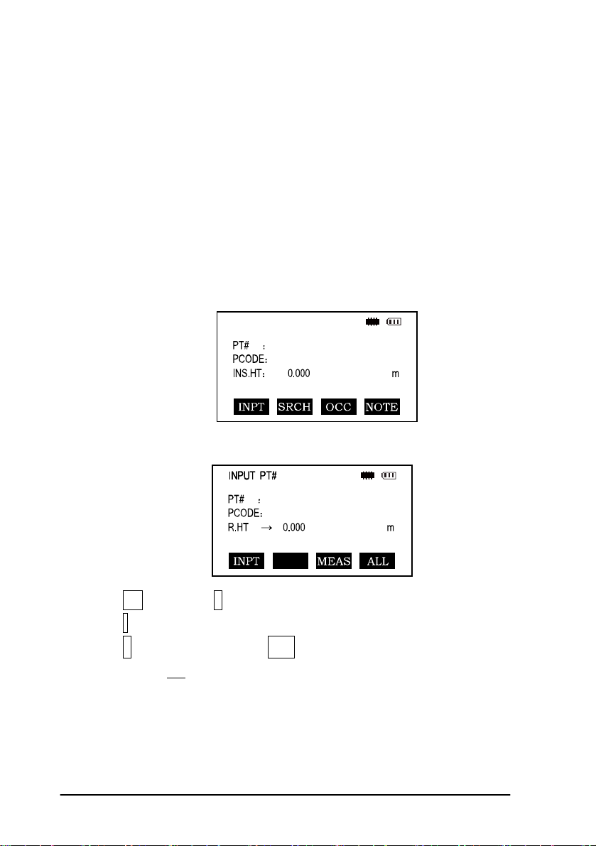
[Example 1] Select INS.HT (instrument height) in the data collection mode
(first press the MENU button then F1: COLLECT DATA and then select the data file
desired. Press F2 to list, the arrow keys to choose and then F4 to select). Press F1
again for OCC.PT# INPUT.
The arrow (
line up or down
Press [▼] move->R..HT
Press F1 INPUT then 1 to input“1”
Press . to input “. ”
Press 5 to input “5 ”, press ENT
Then R. HT =1.5 m
→) indicates an item to enter. Press [▲] [▼] key to move the arrow
19
Page 20
*How to enter characters
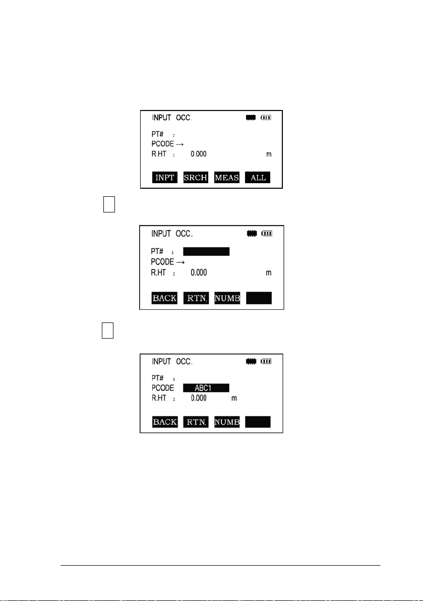
[Example 2] Input the code “ABC1”of instrument point in Data Collection Mode.
1.Move the arrow to PCODE using the [▲]or [▼]key
2.Press F1 (input) key
3.Press F1 key once
Press [7] key once for “A”
Press [7] key twice for “B”
Press [7] key three times for “C”
Press [1] key once for “1” (*Press F3 to switch to NUMB mode first)
Press enter key to finish input
20
Page 21
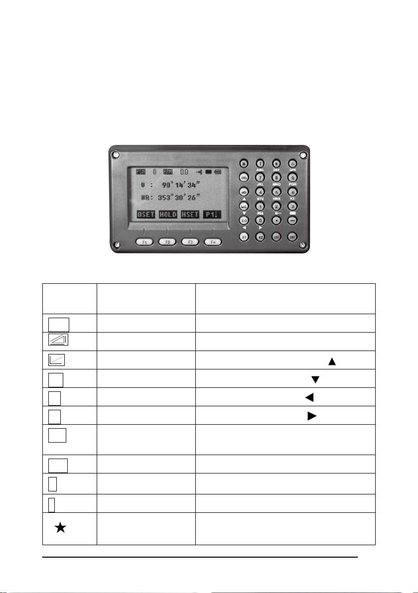
2. FUNCTION KEY AND DISPLAY
2.1 Operating Key
Keys Names Function
ANG Angle meas. key Angle measurement mode
Distance meas. key Distance measurement mode
Coordinate meas. key
Coordinate measurement mode (
Up)
S.O Layout key Layout measurement mode ( Down)
K1 Quick key1 User-defined quick key 1( Left)
K2 Quick key 2 User-defined quick key 2( Right)
ESC Escape key
ENT Enter key
M Menu key Switches menu mode and normal mode
T Shift key Shift distance measuring key
Star key
Return to the measurement mode or
previous layer mode.
Press after confirmation of inputting values
Press once to adjust contrast or twice for
illumination of keypad
21
Page 22
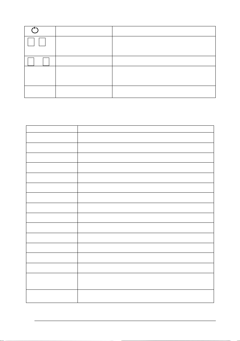
Power key On / Off key press and hold
F1- F4 Soft key ( Function
key)
0- 9 Number key Input numbers
— Minus key Input minus sign, displays electronic
. Point key On / Off laser pointing function
Display marks:
Display Content
V Vertical angle
V% Vertical angle as a percentage (Gradient display)
HR Horizontal angle (right)
HL Horizontal angle (left)
HD Horizontal distance
VD Elevation difference
SD Slope distance
Responds to the message displayed
bubble
22
N North coordinate
E East coordinate
Z Z or elevation coordinate
* EDM working
m/ft Switches units between meters and feet
m Meter unit
S/A Sets temperature, air pressure, prism constant
PSM Prism constant (unit:mm)
PPM Atmospheric correction
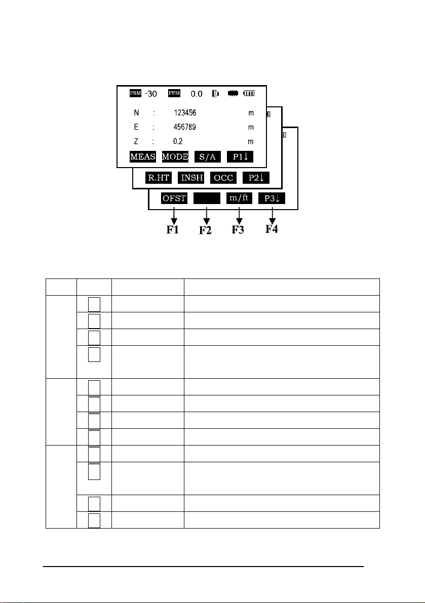
Page 23
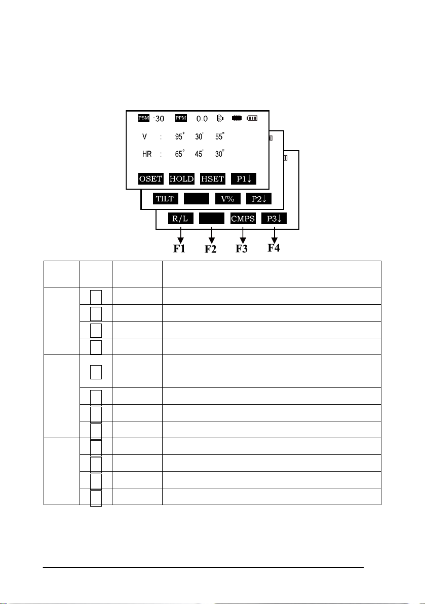
2.2 Function Key
Angle measurement mode (three-page menu)
Page Keys
P1
P2
P3
Display
marks
Function
F1 0SET Horizontal angle is set to 0°0′0″
F2 HOLD Hold the horizontal angle
F3 HSET Set a required horizontal angle by entering numbers
F4
F1 TILT
P1↓ Scroll to the next page (P2)
Tilt correction screen. If the correction is turned on
the display will show the tilt correction value.
F2
F3 V% Vertical angle percent grade (%) mode
F4
P2↓ Scroll to the next page (P3)
F1 R/L Switches Right/Left rotation of horizontal angle
F2
F3 CMPS Switches vertical angle “0” position
F4
P3↓ Scroll to the next page (P1)
23
Page 24
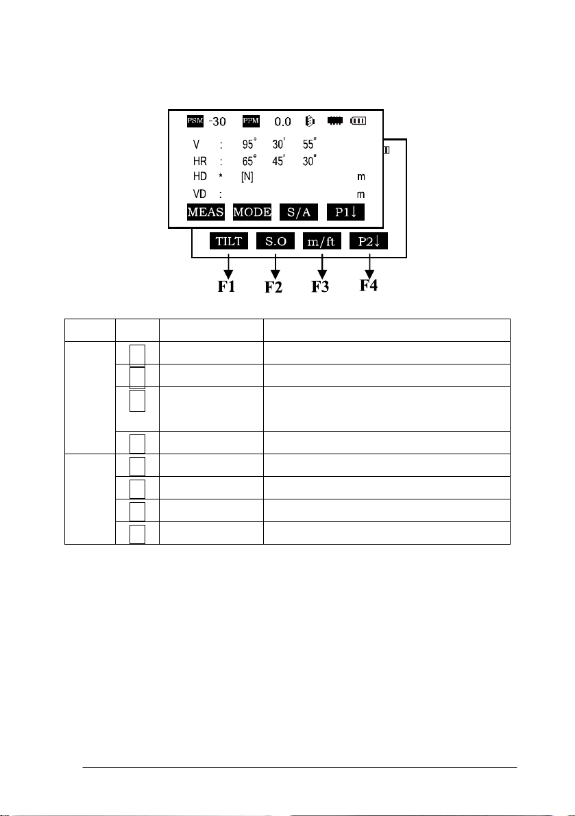
Distance measurement mode (two-page menu)
Page Keys Display marks Function
F1 MEAS Begin measuring
P1
F2 MODE Sets measuring mode, Fine/--/Tracking
F3 S/A Sets temperature, air pressure, prism
constant
P1↓ Scroll to the next page (P2)
P2
F4
F1 OFSET Selects Off-set measurement mode
F2 S.O. Selects Stake Out measurement mode
F3 m / ft Switches units between meters and feet
F4
P2↓ Scroll to the next page (P1)
24
Page 25
Coordinate measurement mode(three-page menu)
Page Keys Display marks Function
F1 MEAS Start measuring
P1
P2
P3
F2 MODE Sets a measuring mode, Fine/Tracking
F3 S/A Sets temperature, air pressure, prism constant
F4
P1↓ The function of soft keys is shown on next
page (P2)
F1 R.HT Sets prism height
F2 INSHT Sets instrument height
F3 OCC Sets instrument coordinate.
F4
P2↓ Shows the function of soft keys on page 3
F1 OFSET Off-set measurement mode
F2 BACKSIGHT Setting a direction angle for backsight
orientation
F3 m / ft Switches meter and feet unit.
F4
P3↓ Shows the function of soft keys on page1
25
Page 26
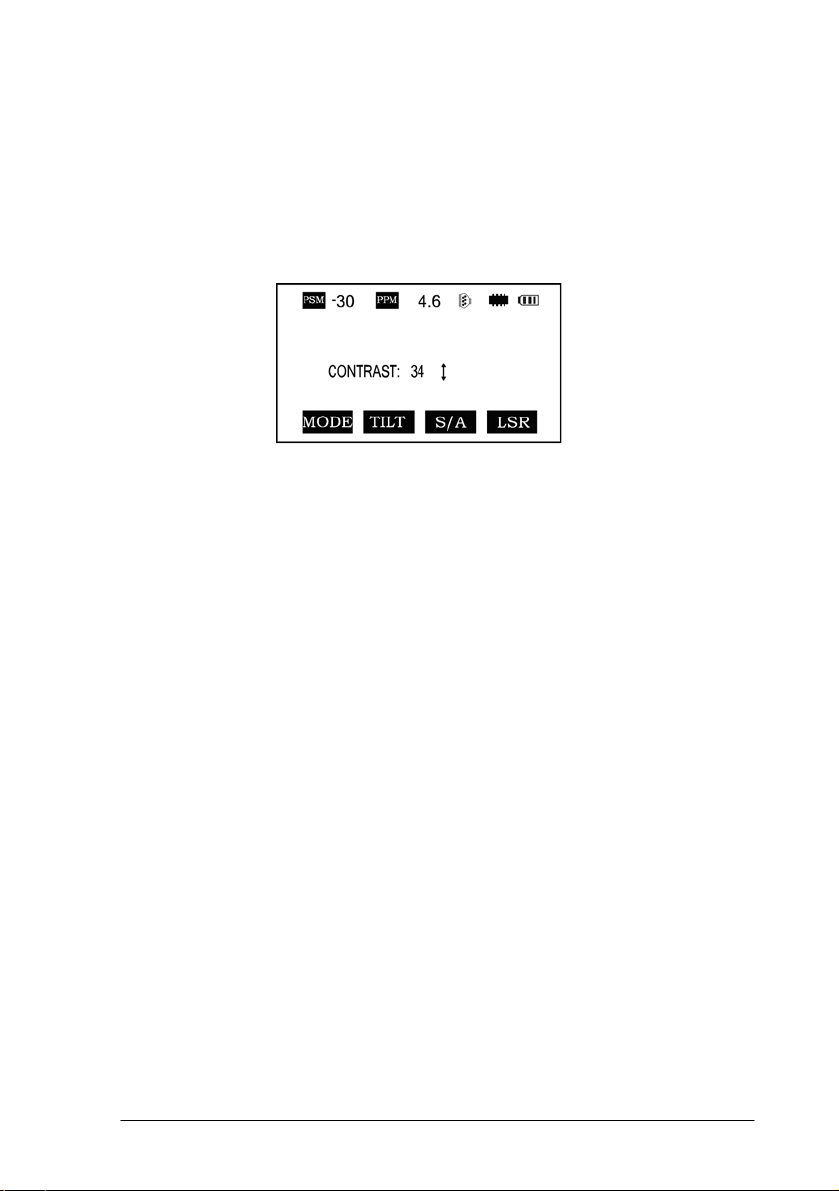
2.3 star-key mode
The total station(non-reflectorless):
Press the star key , following is displayed:
1. Contrat adjustment: After pressing star key, adjust the display contrast by
pressing [▲] or [▼] key.
2. Illumination: After pressing star key, select [Illumination] by pressing
F1(LAMP) key or press star key.
3. Tilt: After pressing star key, select [tilt] by pressing F2 (TILT) key, and
select ON or OFF by pressing F1 or F3 key, press F4 (ENT) key.
4. S/A: After pressing star key, select [S/A] by pressing F3 (S/A) key, then you
can set Prism contrast, air pressure and temperature.
5. Laser plummet: If total station has this function, after pressing star key,
select [laser] by pressing F4 (LSR) key, and select ON or OFF by pressing F1 or F2
key.
*In some interface, you can turn on or turn off panel backlight by press star key
directly.
26
Page 27
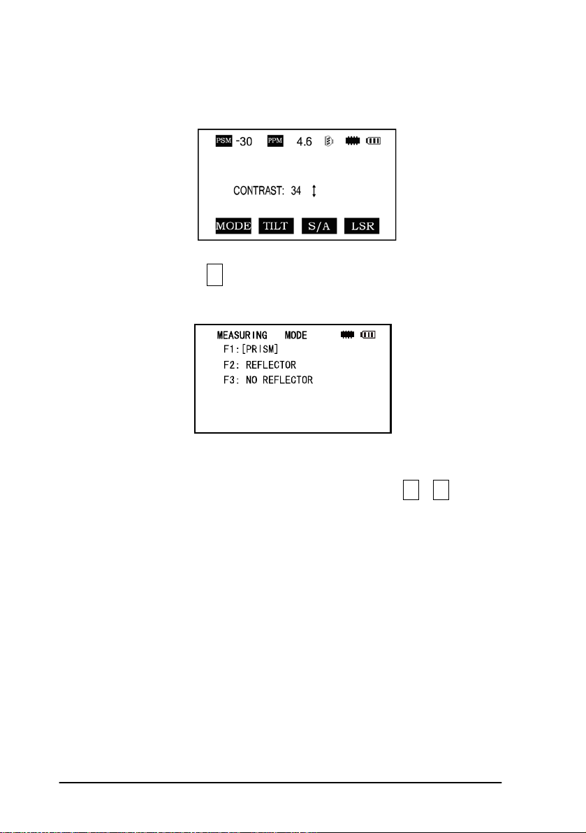
The total station(with reflectorless):
Press the star key , following is displayed:
1.Mode: Press the F1 (mode) key, the following is displayed :
You can select the type of measure mode by pressing the F1—F3 keys.
2.You can turn on the lamp by pressing the star key once more or by pressing
twice from any menu.
2.4 Dot-key Mode
The total station can function as a laser pointer
The laser pointer can be turned on or off by pressing the (.) dot key.
27
Page 28
3. INITIAL SETTINGS
The series total station can be reset to the instruments original factory settings.
See Section 11 “Basic Settings”
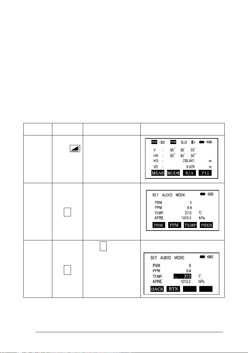
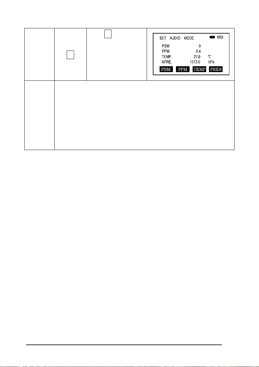
3.1 Setting the Temperature and Atmospheric
Pressure
Measure the surrounding temperature and air pressure in advance. Example:
temperature +25°, air pressure 1017.5 hPa
Procedure
Temp.
Settings
Operation Operating procedure Display
F3
F3
Enter the Distance
Measurement Mode
Press F3 to enter the
S/A screen
Press F3 to enter
temperature section,
enter the correct
temperature, press
the ENT key to set
28
Page 29
Atms.
Pressure
F2
Press F2 key and
enter the air pressure,
press the ENT key to
confirm
Remar
ks
Temperature operating range:-30°~+60℃ or -22~+140℉
Air pressure:560~1066 hPa or 420~800 mmHg or 16.5~31.5 inHg
If the atmospheric correction value calculated from the temperature
and air pressure exceeds the range of ±999.9PPM,the operation will
return to step 4 automatically, and you should enter the data again.
3.2 Setting of the Atmospheric Correction
The infrared emitted by the Total Station varies with the air temperature and
pressure. Once the atmospheric correction value is set the instrument will correct
the distance measuring result automatically.
Air pressure: 1013hPa
Temperature: 20℃
The calculation of atmospheric correction :
ΔS =273.8 0.2900 P / ( 1 + 0.00366T )(ppm)
ΔS:Correction Coefficient (Unit ppm)
P: Air Pressure (Unit : hPa If the unit is mmHg , please convert using
1hPa = 0.75mmHg
T: temperature ( unit℃)
29
Page 30
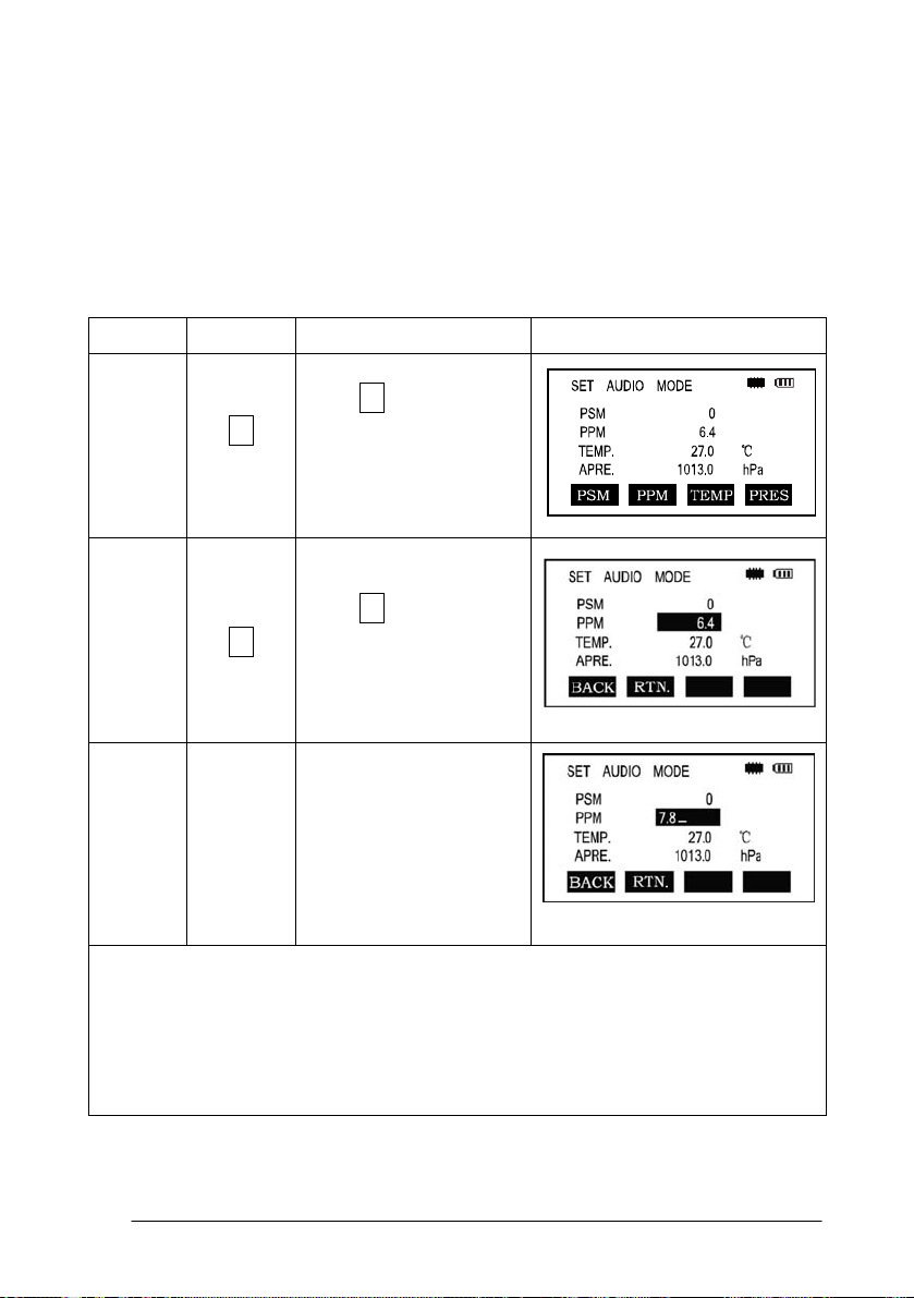
Direct Setting Method of Atmosphere Correction Value
After measuring the temperature and air pressure the atmosphere correction
value can be obtained from an atmospheric correction chart or correction formula
(PPM).
Procedure
F2
*1)See 2.10“How to Enter Alphanumeric Characters”
Input range:-999. 9PPM to +999. 9 Step length: 0 .1PPM
*2) If Temperature and Atmospheric Pressure are reset, the PPM will be
recalculated automatically.
Operation
F3
Enter
value
Operation Procedure Display
Press F3 Key in
distance measurement
or coordinate
measurement mode
Press F2 [ppm] key,
which shows the current
setting value
Enter atmospheric
correction and press
ENT
30
Page 31

3.3 Setting of the Prism Constant
In the factory the prism constant for the total station is set at -30mm. If the
constant of the prism used is not -30mm, you must change this setting. Once the
prism constant is set it will become the new default value until changed.
Procedure Operation Operation Procedure Display
Press F3 ( S/A ) Key
in Distance
F3
② F1
③
Input range:-99. 9mm to +99. 9mm Step length 0. 1mm
Enter
data
Measurement Mode
or Coord.
Measurement Mode.
② Press F1(PRISM)
key
Press F1 (INPUT) key
to enter the Prism
Constant correction
value. *1, press F4 to
confirm and return to
the Setting Mode.
*The total station in reflectorless measuring mode sets the prism constant to 0
automatically.
31
Page 32

3.4 Setting of the Vertical Angle Tilt Correction
When the tilt sensor is activated the instrument automatically corrects the
vertical angle for mislevel. To ensure a precise angle measurement the tilt sensor
must be turned on. The tilt sensor display can also be used to fine level the
instrument. If the (“X TILT OVER”) display appears the instrument is out of the
automatic compensation range and must be leveled manually to within tolerances.
The instruments compensates the vertical angle reading due to inclination of
the standing axis in the X direction.
When the instrument is on an unstable footing or used during a windy day the
display of vertical angle can be unstable. You can turn off the auto tilt correction
function in this case.
Setting the tilt correction
The instrument memorizes the last setting for this feature. To insure the compensator
is on check this setting before operating the instrument.
For operation procedures refer to 11.2.1.
32
Page 33

4.ANGLE MEASUREMENT
4.1 Measuring Horizontal Angle Right and Vertical
Angles
Make sure the angle measurement mode is selected.
Operation procedure Operation
①Collimate the first target
Collimate A
(A)
To set horizontal angle of
target A at 0
00 ’ 00" press the F1
(0SET) key and then press
the F4 (YES) key
③ Collimate the second
target (B)
Collimate B
The required V/H angle to
target B will be displayed
Display
F1
F4
Note : The horizon angle will be saved when the instrument is powered off and
displayed when powered on.
33
Page 34

Reference: How to Collimate
Point the telescope toward a light surface or sky. Turn the diopter ring and adjust the
diopter so that the cross hairs are clearly observed.
Aim the target at the peak of the triangle mark of the sighting collimator. Allow a
certain space between the sighting collimator and yourself for collimating.
Focus the target with the focusing knob.
If parallax is created between the cross hairs and the target when viewing vertically
or horizontally while looking into the telescope, focusing is incorrect or diopter
adjustment is poor.
This adversely affects precision in measurement please eliminate the parallax by
carefully focusing and using the diopter adjustment.
34
Page 35

4.2 Switching Horizontal Angle Right/Left
Make sure the angle measurement mode is selected.
Operation procedure Operation
Press the F4 Key twice to get the
menu to page 3. (P3)
F4
twice
Display
Press the F1(R/L)key.
The Horizontal Right angle mode
F1
(HR) Switches to Horizontal Left
mode (HL)
Measure as HL mode
*Each time the F2 (R/L) key is pressed the HR/HL mode switches
35
Page 36

4.3 Setting of the Horizontal Angle
4.3.1 Setting by Holding the Angle
Make sure the angle measurement mode is selected.
Operation procedure Operation Display
①Set the required horizontal
Display
angle using the horizontal
angle
tangent screw
②Press the F2 (HOLD)key
③Collimate the target Collimate
④Press the F4 (YES) key to
finish holding the horizontal
angle, the display turns back to
the normal
angle measurement mode
*To return to the previous mode, press the ESC key.
F2
F4
36
Page 37

4.3.2 Setting the Horizontal Angle from the Keypad
Make sure the angle measurement mode is selected.
Operation procedure Operation
①Collimate the target Collimate
②Press the F3 (HSET) key
F3
③Input the required horizontal
angle by using the keys, for
example:
150.10.20, inputs
150.10.20
150 10′20″.
ENT
Press ENT
Carry on normal measurement
after entering the required
horizontal angle
Display
37
Page 38

4.4 Vertical Angle Percent Grade (%) Mode
Make sure the angle measurement mode is selected.
Operation procedure Operation
Press F4 key to get the
function on menu page
P2
Press the F3(V%)key * F3
*Each time the F3(V%)key is pressed the display mode switches.
When the angle measured is over 45°(100%)from the horizontal <OVERTOP>
is displayed.
F4
Display
38
Page 39

4.5 Setting the Initial Zenith Angle
Vertical angle is displayed as shown below:
Make sure the angle measurement mode is selected.
Operation procedure Operation Display
Press F4 key twice to get the
menu on page 3 (P3):
F4
twice
Press the F3(CMPS)key * F3
* Each time the F3 key is pressed the display mode switches.
39
Page 40

5. DISTANCE MEASUREMENT
When setting the atmospheric correction obtain the correction value by
measuring the temperature and pressure.
5.1 Setting of the Atmospheric Correction
When setting the atmospheric correction obtain the correction value by
measuring the temperature and pressure. Refer to Section 3.2 “Setting of the
Atmospheric Correction”.
5.2 Setting of the Correction for Prism Constant
The instrument is preset for a Prism Constant value of -30mm at the factory. If
the prism is of another constant the instrument needs to be updated with this
constant. Refer to Chapter 3.3 “Setting of the Prism Constant”. The updated value
is kept in the instrument memory after the power is shut off.
5.3 Distance Measurement (Continuous Measurement)
Make sure the angle measurement mode is selected.
Operation procedure Operation
Collimate the center of prism
*1
40
Collimate
Display
Page 41

Press the key, distance
measurement starts *2 *3;
③The measured distances are
shown (*4,*7) By pressing
the
changes to horizontal (HR),
vertical (V) angle, vertical
distance (VD) and slope
distance (SD)
*1)The total station prism mode collimate center of prism when measuring;
*2)When EDM is working, the “*” mark appears in the display. The total
stations will display “weak signal” when measuring if the signal is weak.
*3)To change the mode from Fine to Tracking, refer to section 5.4 “Fine mode /
Tracking Mode”. To set the distance measurement on when the instrument is
powered up, refer to Chapter 11 “Basic Settings”.
*4)The distance unit indicator "m" (for meter) or “ft” (for feet) appears and
disappears alternatively with a buzzer sounding at every renewal of distance data.
*5) Measurement may repeat automatically in the instrument if the result is
affected by external factors*.
*6)To return to the angle measuring angle mode from the distance-measuring
mode, press the ANG key.
*7)It is possible to choose the display order (HR,HD,VD) or (V, HR,SD) for initial
measuring mode. Refer to Chapter 11 "Basic Settings".
key again the display
41
Page 42

5.4 Changing the Distance Measurement Mode
(Repeat Measurement / Single Measurement/
Track Measurement)
Make sure the angle measurement mode is selected.
Operation procedure Operation Display
Collimate the center of the
prism
Press the key,Continuous
Measurement begins *1;
Press the F2 (MODE) key to
switch between Repeat
Measurement, Single
Measurement and Tracking
Measurement. [N], [1], [T]
Collimate
F2
F1
42
Page 43

*1 It is possible to set the measurement mode for N-times measuring mode or
continuous measurement mode when the power is turned on. Refer to Chapter 11
“Basic Settings”.
5.5 Stake Out (S.O.)
The difference between the measured distance and the input stake out distance
is displayed.
Measured distance - Stake out distance = Displayed value
In a stake out operation you can select either horizontal distance (HD), relative
elevation (VD), and slope distance (SD.)
Operation procedure Operation
Press the F4(↓) key in the distance
measuring mode to menu P2
Press the F2 (S.O) key
The data previously set is shown
F4
F2
Display
43
Page 44

Select the measuring mode by
pressing the F2 to F4 keys. F2:HD,
F3:VD,
F4:SD
F1
Pris
m
Enter 350
Enter the distance 350 , press F4
Collimate the target (Prism),
measurement starts. The difference
between the measured distance and
the
stake out distance is displayed.
Move the target until the difference
becomes 0.
To return to normal distance measurement mode, stake out distance to “0” or
switch to other measurement mode.
F4
Collimate
44
Page 45

5.6 Offset Measurement
There are four offset measurement modes:
1. Angle offset
2. Distance offset
3. Plane offset
4. Column offset
5.6.1 Angle Offset
This mode is useful when it is difficult to set up the prism directly on target; for
example at the center of a tree. Place the prism at the same horizontal distance from
the instrument as that of point A0 to measure. To measure the coordinates of the
center position use the offset measurement after setting the instrument height/prism
height.
When measuring coordinates of ground point AI: Set the instrument
height/Prism height
When measuring coordinates of point A0: Set the instrument height only (Set
the prism height to 0)
45
Page 46

Set the instrument height/prism height before proceeding to the offset
measurement mode.
When setting the coordinate value for the occupied station, refer to Section 6.2
“Setting Coordinate Values of an Occupied Point”.
Operation procedure Operation Display
Press the F4( ↓ ) key from
distance
measuring mode to get the
function on menu P2
F4
Press F1 (OFSET) key F1
46
Page 47

Press F1 (ANG.OFFSET) key F1
Collimate prism P, and press the
F1
(MEAS) key.
The horizontal distance from the
instrument to the prism will be
measured.
Collimate point AO using the
horizontal motion clamp and
horizontal tangent screw.
Show the north coordinate, east
coordinate and z coordinate of
waited measuring point by
pressing
To return to procedure 3, press F4 (NEXT) key
key.
Collimate
[P]
F1
Collimate
AO
To return to the previous mode, press ESC key
47
Page 48

5.6.2 Distance Offset Measurement
Measuring the distance and coordinate of a pond or a tree of which the radius is
known. Measuring the distance or coordinate to P0 point, input oHD value as an
offset value and measure P1 point as shown in the drawing. The display shows
distance or coordinate value to P0 point.
When setting the coordinate value for the occupied station, refer to Section 6.2
‘Setting Coordinate of Occupied Point’
Operation procedure Operation Display
①Press the F4 (↓) key from
distance measuring mode to get
the function on menu P2
48
F4
Page 49

②Press F1 (OFSET) key. F1
③Press F2 (DIST OFSET) key,
enter the measurement of
DIST.OFFSET
④Enter R HD,
press ENT key *1
⑤Enter forward HD,
press ENT key *2
⑥Collimate Prism P1, and press
F1 (MEAS) key.
F2
Enter R
HD
ENT
Enter
forward HD
ENT
Collimate
Measuring will start.
After measuring, the result
added
offset value will be show。
P1
F1
49
Page 50

⑦Show the coordinate of Point
P0
To return to procedure 4,press F1 (NEXT) key
To return to the previous mode, press ESC key
*1)*2)refer to section 8.3.2 “Distance Offset Measurement”
5.6.3 Plane Offset Measurement
Used to facilitate distance or coordinate measuring for a given plane.
Three random prism points (P1, P2, P3) on a plane will be measured at first in the
plane-offset measurement to determine the measured plane. Collimate the
measuring target point (P0) then the instrument will calculate and display coordinate
and distance values of the cross point between collimation axis and the plane.
50
Page 51

When setting the coordinate value for the occupied station, refer to Section 7.2
‘Setting Coordinate Value of Occupied Point’.
Operation procedure Operation Display
①Press the F4 (↓) key from
distance
F4
measuring mode to get the
function on page 2.
②Press F1 (OFSET) key F1
③Press F3 (PLANE OFSET) key
F3
④Collimate Prism P1, and press
F1 (MEAS) key.
Collimate
N-time measuring will start.
After measuring, the display will
show the second point
P1
F1
measurement.
51
Page 52

⑤Measure the second and third
points in the same way.
The instrument calculates and
displays coordinate and distance
values of the cross point between
the collimation axis and of the
plane *1*2
⑥Collimate the edge (P0) of the
plane *3*4
Collimate
P2
F1
Collimate
P3
F1
Collimate
P0
⑦By pressing key each
time,horizontal distance, relative
elevation and slope distance are
shown in sequence.
To show the coordinate of the
point (P0), press
52
key.
Page 53

*1 ) In case the calculation of plane was not successful by the measured three
points, error displays. Start measuring over again from the first point.
*2 ) Data display is the mode beforehand of offset measurement mode.
*3 ) Error will be displayed when collimated to the direction which does not cross
with determined plane.
*4 ) The reflector height of the target point P0 is set to zero automatically.
5.6.4 Column Offset Measurement
If it is possible to measure circumscription point (P 1) of Column directly the
distance to the center of the column (P0), coordinate and direction angle can be
calculated by measured circumscription points (P2) and (P3).
The direction angle of the center of the column is 1/2 of total direction angle of
circumscription points (P2) and (P3).
53
Page 54

When setting the coordinate value for the occupied station, refer to Section 6.2
‘Setting Coordinate Values of Occupied Point’.
Operation procedure Operation Display
Press the F4 (↓) key from
distance
measuring mode to get the
function on menu P2
F4
Press F1 (OFSET) key F1
Press F4 (COLUMN
OFFSET)key
Collimate the center of the
column
(P1) and press F1 (MEAS)
key
N-time measuring will start.
After the measurement,
angle-measuring display of
the left side (P2) will be
shown.
54
F4
Collimate
P1
F1
Page 55

Collimate the left side of
column(P2) and press F4
(SET) key.
After measurement, angle
measuring
display of the right side (P3)
will be shown.
⑥Collimate the right side of
the column (P3) and press
F4 (SET) key.
After measurement, the
distance between the
instrument and the center of
column (P0) will be
calculated.
To show the coordinate of
Collimate
P2
F4
Collimate
P3
F4
point P0,press key.
*1*2
*1)To return to procedure 5, press F4 (NEXT) key
*2)To escape the measuring,press ESC key,the display returns to the previous
mode.
55
Page 56

6. COORDINATE MEASUREMENT
6.1 Execution of Coordinate Measurement
Measure the coordinates by entering the instrument height and prism height,
coordinates of unknown Point will be measured directly.
* When setting coordinate values of occupied point, see Section 6.2 “Setting
Coordinate Values of Occupied Station Point”.
* When setting the instrument height and prism height, see Section 6.3
“Setting Height of the Instrument” and 6.4 “Setting Height of Target (prism
Height)”.
* To set backsight, determine the backsight azimuth or check the known
azimuth, coordinate and distance.
The coordinates of the unknown point are calculated as shown below and displayed:
Coordinates of occupied point:(N0,E0,Z0)
Instrument height :INS.HT
Prism height: R.HT
Vertical distance (Relative elevation):Z(VD)
Coordinates of the center of the prism, originated from the center point of the
instrument:(n,e,z)
Coordinates of unknown point:(N1,E1,Z1)
N1=N0+n
E1=E0+e
Z1=Z0+INS.HT+Z-R.HT
Center point of the instrument (N0, E0, Z0+INS.HT)
56
Page 57

When doing coordinate measurement coordinates of occupied point, the instrument
height, the prism height and back sight azimuth should be set.
Operation procedure Operation Display
Set the direction angle of
known
point A *1 )
Set
direction
angle
Collimate target prism B, and
press
key
Collimate
target
prism
*1Refer to Section 4.3 “Setting of Horizontal Angle”.
In case the coordinate of instrument point is not entered, (0,0,0) will be used as the
default for the instrument point. The prism height will be calculated as 0 when the
prism height is not set.
57
Page 58

6.2 Setting Coordinate Values of Occupied Point
Set the coordinates of the instrument (occupied point) according to known
values and the instrument automatically converts and displays the unknown point
(prism point) coordinates following the observation.
The instrument retains the coordinates of the occupied point after turning the
power off.
58
Page 59

Operation procedure Operation Display
Press the F4 (P1↓) key from
the
coordinate measurement mode
F4
to get the function on menu P2.
Press the F3(OCC)key F3
Enter
③Enter N coordinate value
data
ENT
④Enter E and Z coordinate
values in the same manner.
Enter
After entering the
data
values, the display returns to
ENT
the coordinate measuring
display menu.
Input range:-999999.999m/ft ≤ N、E、Z ≤ +999999.999m/ft
59
Page 60

6.3 Setting Height of the Instrument
The instrument height value will be retained after the instrument is powered off.
Operation procedure Operation Display
Press the F4 (P1↓) key from the
F4
coordinate measurement mode to
access the P2 menu screen.
② Press the F2 (I.HT) key,
F2
The current value is displayed.
Enter the instrument height and
press the ENT key to get to the
coordinate measuring display
Input range:
—999.999≤INS.HT≤+999.999m
60
Enter the
I.H.
ENT
Page 61

6.4 Setting Height of Target (Prism Height)
This mode can be used to obtain z coordinate values. The target height value
will be retained after the instrument is powered off.
Operation procedure Operation Display
Press the F4 (P1↓) key from the
coordinate measurement mode to
access the P2 menu screen.
②Press the F1 (R.HT) key
The current value is displayed.
Enter the prism height, then press
the ENT key to get to the
coordinate measuring display
Input range:
F4
F1
Enter the
prism
height
ENT
—999.999m≤prism height≤+999.999m/ft
61
Page 62

7. SURVEYING PROGRAM
Surveying Program Mode (programs)
By pressing the menu key M , the instrument will be in Menu Mode.
7.1 Remote Elevation Measurement(REM)
To obtain elevation of the point at which setting the target prism is not possible,
place the prism at any point on the vertical line from the target then carry out REM
procedure as follows.
62
Page 63

1)With prism height (h) input
Operation procedure Operation Display
Press the M Key
M
Press the F2 key,enter MEAS
F2
PROGRAM. menu
③Press the F1(REM)key F1
④Press the F1 key F1
⑤Enter prism height (1.3 is an
example in meters)
F1
Enter
prism
height
1.3
F4
63
Page 64

⑥Collimate prism
⑦Press the F1 (MEAS) key,
measurement starts. Horizontal
distance (HD) between the
instrument and prism will be
shown.
⑧Press the F4 (SET)
The prism position will be
decided.
⑨ Collimate target K.
Vertical distance
(VD) will be shown.
Collimate
Prism
F1
F4
Collimate
K
To return to procedure 5,press F2 (R.HT) key.
To return to procedure 6,press F3 (HD) key.
To return to PROGRAMS Menu, press the ESC key.
64
Page 65

2)Without prism height input
Operation procedure Operation Display
Press the M menu key M
Press the F2 key,enter the
F2
measure programs menu.
③Press the F1 (REM) Key. F1
④Press the F2 key to select the
F2
mode without prism height.
Collimate prism, press the F1
(MEAS) key. Measuring starts.
Collimate
Horizontal distance (HD)
between the instrument and
target
target will be shown..
65
Page 66

⑥Press the F4 (SET)
The target position will be
decided.
F4
Collimate ground point G ,
press the F4 (SET) key. The
position of
point G will be decided
Collimate target K
Vertical distance (VD) will be
shown
To return to procedure 5, press the F3 (HD) key.
To return to procedure 6, press the F2 (Vang) key.
To return to PROGRAMS Menu, press the ESC key.
F4
Collimate
K
7.2 Missing Line Measurement (MLM)
Measurement for horizontal distance (dHD) , slope distance (dVD),elevation
(dVR) and horizontal bearing (HR) between two target prisms.
It is possible to enter the coordinate value directly or calculate from coordinate
data file.
MLM Mode has two modes:
66
Page 67

1. MLM-1 (A-B, A-C): Measurement A-B, A-C, A-D
2. MLM-2 (A-B, B-C): Measurement A-B, B-C, C-D
It is necessary to set the direction angle of the instrument.
[Example] MLM-1 (A-B, A-C)
Procedure of MLM-2(A-B,B-C)mode is completely the same as that of
MLM-1 mode.
Operation procedure Operation Display
M
①Press the M menu key
67
Page 68

② Press the F2 key, enter
F2
MEAS PROGRAMS
③Press the F2 (MLM) key F2
Enter file
④Enter file name
name
⑤Press ENT key. ENT
⑥Press the F1 key F1
68
Page 69

⑦Collimate prism A, and press
the F1 (MEAS) key.
Horizontal distance (HD)
between the instrument and
target A will be shown.
⑧Press the F4 (SET) key
The position of the target is
confirmed.
⑨Collimate prism B and press
the F1 (MEAS) key. Horizontal
distance (HD) between the
instrument and target B will be
shown..
⑩Press the F4 (SET) key
The horizontal distance(dHD)
Collimate
A
F1
F4
Collimate
B
F1
and relative
elevation (dVD) between target
A and B.
⑾ To measure the distance
between points
A and C, press the F4 (NEXT)
key*1)
F4
F4
69
Page 70

⑿ Collimate point C (target C)
and press the F1 (MEAS) key.
Horizontal distance (HD)
between the instrument and
Collimate
C
F1
target C will be shown.
⒀Press the F4 (SET) key. The
horizontal distance (dHD) and
relative elevation (dvD) between
F4
taget A and C will be shown
⒁ To measure the distance
between points
A and D, repeat procedure 12
to 14 *
*To return to Previous mode , press the ESC key.
70
Page 71

HOW TO USE COORDINATE DATA
It is possible to input coordinate values directly or calculate from a coordinate
data file.
[Example] Input the data (NEZ) directly:
Operation procedure Operation Display
①Press the F3(NEZ) key F3
② Press the F4(coordinate)
F4
key
③Enter coordinate, press
ENT
ENT key to get to the second
point.
*To return to PROGRAMS Menu, press the ESC key.
71
Page 72

7.3 Area Calculation
This mode calculates the area of an enclosed figure.
There are two area calculation methods as follows:
1) Area calculation from Coordinate data file
2) Area calculation from measured data
Note:
Area is not calculated correctly if observed lines cross each other.
It is not possible to calculate area from a mix of coordinate file data and measured
data.
The number of points used for calculation is not limited.
The area to be calculated shall not exceed 200000 sqm. (approx. 49 acres)
1) Area calculation from Coordinate data file
Operation procedure Operation Display
①Press M menu key M
②Press the F2 key, enter the
F2
Measurement Program.
72
Page 73

③Press F3 (AREA) key F3
Press F1 (FILE DATA) key F1
Enter file name or press F2 for
LIST. Press ENT key, Initial
Enter
File name
display will be shown .
ENT
⑥Press F4 (NEXT) key
The top of the file data
(DATA-01) will be set and the
second point number will be
F4
shown.
Repeat pressing F4 (NEXT)
key to set required number of
the points. When 3 points are
set, the area surrounded by the
F4
points is calculated and the
result will be shown.
* To set the required point number, press F1 (PT#) key.
* To show the list of the coordinate data in the file, press F2 (LIST) key.
73
Page 74

2) Area calculation from measured data
Operation procedure Operation Display
①Press M menu key M
②Press the F2 key, enter the
F2
Measurement Program.
③Press F3 (AREA) key F3
Press the F2
(MEASUREMENT) key
F2
Collimate a target or prism and
press the F1 (MEAS) key.
Collimate
Prism
Measuring starts *
74
F1
Page 75

Press the F4 key to affirm F4
⑦Collimate a next prism and
press F1 (MEAS) key. When 3
points are set, the area
surrounded by the points is
calculated and the result will be
shown.
*1 Measurement is N-time measurement mode.
Collimate
F1
75
Page 76

7.4 Setting Z Coordinate of Occupied Point
Occupied point coordinate data and known point actual measuring data can be
utilized, zcoordinate of occupied point is calculated and reset.
Known point data from a coordinate file can used.
1 ) Setting z coordinate of occupied point
[Example setting] Using coordinate data file
Operation procedure Operation Display
①Press the M menu key M
②Press the F2 key ,enter
PROGRAMS
③Press the F4 (Z
COORDINATE key
76
F2
F4
Page 77

④Enter the File Name then
press ENT to affirm.
Press the F2 (REF. MEAS)
key and enter the point
number (press F2 for LIST)
After input the PT#, press
the ENT key, the coordinate
of this point is shown.
Input
File Name
ENT
F2
ENT
⑦Press the F4 (YES) key to
confirm instrument height
setting display will be shown.
F4
Enter the instrument height,
Enter
press ENT key. Press F1
INS.HT
(MEAS) for observation
ENT
results
For more information about data file, see chapter 10 “Memory Management
Mode”.
77
Page 78

2)Z coordinate calculation from known point measuring data
[Example setting] Using coordinate data file.
Operation procedure Operation Display
Press the M menu key M
Press the F2 key, enter MEAS
F2
PROGRAMS.
Press the F4 (Z
F4
COORDINATE) key
INPUT
Enter the File Name then
File Name
press ENT to affirm.
ENT
⑤Press the F2 key F2
78
Page 79

⑥Enter the point number in
coordinate data file, press
ENT to affirm.
Enter PT#
ENT
⑦Press the F4 (YES) key to
affirm
⑧Enter the height then press
the ENT to affirm.
⑨Collimate a prism on the
point and press the F1
(MEAS)key.
Measuring starts *1
F4
Enter R.HT
ENT
Collimate P
F1
⑩Press the F4 (CAL) key *2
Z: Z coordinate
F4
79
Page 80

⑾Press the F4 (SET) key *3
Z coordinate of the occupied
point will be set. Backsight
point masuring screen will be
shown.
⑿Press the F4 (YES) key.
Horizontal angle will be set.
The display returns to
Measurement Programs menu.
*1 Measurement is Fine Single measurement mode.
*2 To measure other points, press the F1 (NEXT) key.
*3 Pressing the F1 or F3 key, the display will be changed alternately.
F4
F4
7.5 Point to Line Measurement
This mode is used to obtain the coordinate data of an unknown occupied point
from a known point and a known line. An observation will need to be taken at the
known point A and along the line N designated for the example as B. After
measuring the 2 points the coordinate and the direction angle of the instrument will
be calculated and recorded.
80
Page 81

Operation procedure Operation Display
①Press the M menu key M
②Press the F2 key for the
F2
Measure Program menu
③Press the ▼ key ▼
81
Page 82

④Press F1 (POINT TO LINE)
key
⑤ Enter instrument height.
Press ENT
⑥Enter reflector (PI) height at
point A. Press ENT
F1
Enter
INS.HT
ENT
Enter
R.HT
ENT
⑦Collimate prism A (Origin)
and press F1 (MEAS) key.
Measuring starts.* 1 Press
F4
Input height of target B height
will be shown.
82
Collimate
P1
F1
F4
Page 83

⑧ Enter reflector height of
point B. Press ENT
Enter
INS.HT
ENT
⑨Collimate prism B (P2) and
press F1 (MEAS) key.
Measuring starts.* 1 Press
F4
The coordinate data and
direction angle of the
instrument is calculated and
recorded.
⑩ Press F1 (NEZ) key to
measure
other points *2 *3.
⑾Collimate prism, press F4
(MEAS) key. Measuring
starts *3)
The result will be shown.*4)
Collimate
P2
F1
F4
Collimate
P
F1
F4
*1)Measurement is N-time measurement mode.
*2)Press F2 (S.CO) key to show the new occupied data.
*3)Measurement is N-time measurement mode.
*4)To return to previous mode, press F1 (EXIT) key.
83
Page 84

7.6 Road Construction
By using this program you can define a straight line, a curve, or a transition curve as
a reference to make a measurement and set out. This program will do the
computation of coordinates and setting out of the design point according to the stake
number and deviation which are defined by the roads design.
In order to use this program the observation station coordinates and backsight
azimuth angle need to be set.
7.6.1 Design: Horizontal Alignment
Horizontal alignment consisted of following elements: start point, straight line,
circular curve , transition curve, INTG, WIDE and PEG.
The define option will prompt for the start details(chainage,NEZ,starting
azimuth).
Enter these details in the screen, press [ENT] key to show the mail input routine
screen:
84
Page 85

top right corner of the screen shows the number of horizontal alignment.
The main line input screen displays current chainage and the bearing angle (the
tangent line from the chainage) and the function key (For creating new line). System
provides three functions: defining straight line, circular curve, transition curve.
Select a function key, enter the detailed information of the chainage, the alignment
elements will be created. Press ENT key, the new chainage and bearing angle will be
calculated automatically and the main alignment screen will be restored. Now other
line style can be defined, the new elements can be added only in the end of the
original alignment file.
Operation procedure is as follows:
Operation procedure Operation Display
In main menu, press F2 key to
get MEAS PROGRAM menu,
press F4 key to get second page
of MEAS PROGRAM menu.
Press F2(ROAD MEASURE)
key
Enter file name, then press ENT
key.
F2
F4
F2
F2
85
Page 86

Press F1(ROAD DESIGN)key.
F1
Press F1(DESIGN H-LINE)
F1
key for the H-line menu.
Input starting chainage, northing
coordinate, easting coordinate
Input
starting
and starting azimuth. Press ENT
key to show the main input
routine screen.
data
ENT
In main input routine screen we can add straight line, circular curve and transition
curve to the end of current curve. Select the desired option by pressing F1-F3 keys.
Straight line
When the start point or other line style is well defined it allows you to easily define a
straight line. A straight line length value cannot be negative.
86
Page 87

Operation procedure Operation Display
Press F1(Line)key from HZ AL
F1
menu to get BEELINE.
Enter
After entering the length of the
line press ENT key.
length
ENT
Return to HZ AL menu.
Circular Curve
Press F2 key (ARC) in the “HZ AL Screen”, the circular curve can be defined.
Circular curves consists of Arc length and the Radius. The radius value rule:
Looking along the forward direction of the curve, when the curve rotates to right, the
radius value is positive. When the curve rotates to left, the radius value is negative.
The arc length cannot be negative.
87
Page 88

Operation procedure Operation Display
Press F2(ARC) key from
H-LINE menu to get ARC.
Input the radius of the ARC
(R) and press the ENT key.
Input the length of the ARC (L)
and press the ENT key.
Return to HZ AL menu with
calculated values.
88
F2
Input R
ENT
INPUT L
ENT
Page 89

Transition curve
Press F3 key in the “Main Line Input Screen” and a transition curve can be
defined. The inputting of transition curve consists of transition curve parameter
“A”,starting radius, and resending radius. If the input radius is ∞ you can
input 0 as its value.
The rule of transition curve parameter A : Looking along the forward direction of the
curve. When the curve rotates to right, the radius value is positive. When the curve
rotates to left, the radius value is negative.
Operation procedure Operation Display
Press F3 key from H-Line
F3
menu on page 1
Enter A
Input A,press ENT key.
Input radius,press ENT key.
ENT
Enter R
ENT
89
Page 90

Instrument returns to previous
mode with solution.
Stake Spacing(INTG)
Press F1 (INTG) on the second page of the main alignment screen then enter into the
setting interface of stake spacing interval which needs to be greater than 0.
Operation procedure Operation Display
Press F4 on the main
alignment screen (1/2) to enter
into the main alignment
screen (2/2)
Press F1 to enter into the
input interface of stakes space
Return to the main alignment
screen.
Remarks: the stake spacing can be input only once but can be modified during
editing of the horizontal alignment.
90
F4
Enter space
ENT
Page 91

Road Widening Stake Number(WIDE)
On the second page of the main alignment screen, press F2 (WIDE) to enter into the
road widening stake data input interface, and then input the stake number of
widening point, left road width and right road width.
Operation procedure Operation Display
Press F4 on the main
alignment screen (1/2) to enter
into the P2 alignment screen
(2/2).
Press F2 (WIDE) to enter into
the input interface of road
widening stake number.
Input the stake number, left
road width and right road
width, and press ENT to
confirm.
Remarks: The data of each road widening point will determine the road width
between this stake number and next widening point stake number.
F4
F2
Enter data
ENT
91
Page 92

Additional stake number(PEG)
On the second page of the main alignment screen, press F3 (PEG) to enter into the
input interface of addition stake data, and then input the stake number of the
additional staking point, left road width and right road width.
Operation procedure Operation Display
Press F4 on the main
alignment screen (1/2) to
enter into the main alignment
screen (2/2).
Press F3 (PEG) to enter into
the input interface of
additional stake number.
Input the stake number, left
road width and right road
width, and press ENT to
confirm.
Remarks: Two or more additional stake points can be input.
F4
F3
Enter data
ENT
92
Page 93

7.6.2 Editing horizontal alignment data
You can edit the horizontal alignment after input.
From the Road Design Menu select F2: EDIT H-LINE
The function of the soft keys are as follows:
[FST]:Press this key to go to the start of the file,and show the first alignment data;
[LST]:Press this key to go to the end of the file,and show the last alignment data;
[EDIT]:To edit the current alignment data;
[SRCH]:Search the alignment data by inputting chainage;
It is possible to edit data by using the above function keys. After entering the data to
be modified press [ENT] key to record the modified data.
93
Page 94

Operation procedure Operation Display
Press F2 (Edit horizontal
alignment) on the road design
menu to enter into the horizontal
alignment editing interface.
Through pressing [ ▲ ] or [▼],
select the alignment data which is
required to be modified, and press
F1 (edit) to edit it, and finally
press ENT (ENTER) to confirm.
*1)
Return to the alignment interface,
the modified alignment data will be
displayed, and then continue to
modify the other alignment data as
needed
F2
[▲]or[▼]
F1
Enter data
ENT
*1 Or press F4 (search), then input the stake number of the alignment data
(chainage) which is required to be modified.
94
Page 95

7.6.3 Receiving horizontal alignment
You upload a prepared file of horizontal alignment data from a computer for the
alignment work before setting out.
There are two methods to upload data to the instrument.
1. Directly upload the alignment data to the current operating internal memory
from a computer through a data cable (RS-232).
Refer to 10.8 for the operation method
2. Store the alignment data on an SD card, insert the SD card into the
instrument and then copy data from SD card to the memory.
Refer to 10.9 for the operation procedures.
The horizontal alignment data format is in the following format:
Number Data Format Meaning of Parameters
1 start Z,X,Y,a
Initial Point: Stake number of initial point Z, coordinate X,
coordinate Y, initial azimuth a
2 Line Lz Straight line data: the length of straight line Lz
3 spiral A,Rs,Re
4 arc R,Ly
5 wide Zi,wLi,wRi
Transition curve data: transition curve parameter A, radius
of initial point Rs, radius of end point Re.
Circular curve data: radius of circular curve R, curve
length Ly.
Widening point data: initiation stake number Zi, width of
left road wLi, width of right road wRi.
6 integer L0 Stake Space: the length of stake space is LO
7 peg Zj,wLj,wRj
Additional stake point data: additional stake number Zj,
left road width wLj, right road width wRj
95
Page 96

Explanation:
1. The data in the first row is the initial point data, and only one point can be
entered.
2. The data in the second, third, fourth rows is element data, any combination can be
input according to the requirements.
3. The data in the fifth, sixth, and seventh rows is auxiliary calculation data,
choosing whether to enter or not according to the requirements as an option, the
default step length is 20m. Only one staking space is available.
4. The transition curve parameter A and circular curve radius R as needed (sign as
per the direction of route, curve to left is negative, and curve to right is positive), all
other parameters are positive.
5. When the radius of circular curve is ∞, the input radius is 0.
Convert the designed alignment data into *.HAL file using transmission software,
then copy the data to SD card or the memory.
For example:
start 0,2541930.604,502841.293,191.5644
line 452.484
arc 1200,165.885
spiral -90,1e20,130
arc -130,214.928
spiral 110,1e20,280
arc 280,77.151
spiral 110,280,1e20
line 100.978
96
Page 97

integer 20
wide 0,0,6.5
wide 130.945,1.8,6.5
wide 400,4.5,4.5
wide 1040,0,6.5
peg 130.945,1.8,6.5
peg 220,1.8,0
peg 240,2.338,0
peg 260,2.878,0
peg 1000,4.5,5.28
peg 1020,4.5,6.038
peg 1033.721,4.5,6.48
97
Page 98

7.6.4 Deleting horizontal alignment data
The horizontal alignment data in the internal memory can be deleted with the
procedure as follows:
Operation procedure Operation Display
Press F2 (road measurement) in
the menu of Measurement
Program and choose a file.
Press F3 (DEL HZ AL DATA) F3
Press F4 (Yes), the current
selected horizontal alignment
data will be deleted.
F2
Select a file
ENT
7.6.5 DESIGN: VERTICAL CURVE
A vertical curve consists of series of intersection points. The intersection point
consists of a chainage, elevation and curve length. The start and end intersection
points must be a zero curve length.
98
Page 99

Intersection points can be entered in any order. After entering a point data press
ENT to save it and advance to enter the next point. Press ESC to exit without saving.
Operation procedure Operation Display
Press F2 key from the menu to
get MEAS PROGRAM. Press []
for page 2/2
Press F2(ROAD MEASURE)
key
Input file name, then press
ENT key
F2
F2
ENT
99
Page 100

Press F1(ROAD DESIGN)key
Press F3(DESIGN V AL)key F3
F1
Input the CH, H and L of the
first point,then press ENT
key *1
After inputting each point the
menu will advance to the next
point. ESC to exit.
*1 The start and end intersection points must be a zero curve length.
Enter data
ENT
100
 Loading...