

Page 1
Renewable Energy Education Set
ASSEMBLY GUIDE
Battery operation instructions:
1. The removing and inserting of batteries is to be
Model No.: FCJJ-37
Warning
To avoid the risk of property damage, serious injury or
death:
This kit should only be used by persons 12 years old
and up, and only under the supervision of adults who
have familiarized themselves with the safety measures
described in the kit. Keep small children and animals
away, as it contains small parts that could be
swallowed. Read the instructions before use and have
them ready for reference.
Renewable Energy Education Set
What you need:
IMPORTANT: Use common sense when connecting the parts described in this guide. Improper
connections can cause failure and permanent damage to your equipment.
REES
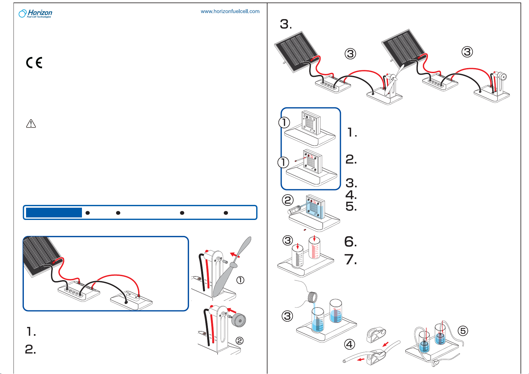
Experiment 1: Use a Solar Panel to Power
the LED Module
Connect the cables to the solar cell/panel and
circuit board to power LED module as shown. Make
sure black and red cables are used with the red
and black terminals respectively.
EXPERIMENT 1
Experiment 2: Use a Solar Panel to Power the Small
Fan/Wheel Motor Module
Assembly of the small electric fan:
Connect small round white adapter to the motor axis. Connect the fan
blade to the adapter.
Assembly of the car wheel:
Firmly connect the other (tapered) white adapter to the motor axis.
Attach the small wheel to the adapter.
AA batteries=2 Units Water=100ml
conducted by the adults only. Unscrew the screw holding
the battery pack’s cover in place using a screw driver. Once
the screw is removed open the battery pack and take out
the batteries using your fingers. Do not use a metal
object.When inserting the batteries make sure that you are
doing so with the correct polarity (the positive end of the
battery must match up with the “+” and the negative end of
the battery must match up with the “-” indicated on the
battery pack), close the battery pack and secure its cover by
tightening the screw with a screw driver.
2. Non-rechargeable batteries are not to be recharged.
3. Different types of batteries such as rechargable, alkline
and standard batteries or new and used batteries are not to
be mixed and should be used separately.
4. The battery pack cables are not to be inserted into an AC
socket.
5. The supply terminals of the battery pack are not to be
short-circuited.
6. The two spare red&black cables are not to be inserted
into an AC socket.
7. Exhausted batteries are to be removed from the battery pack.
ASSEMBLY GUIDE
Scissors
EXPERIMENT 2
Connect the solar panel to the circuit board then to the motor base as shown. The fan may need
to be flicked with your finger to start.
Distilled water
EXPERIMENT 3
Experiment 3: Preparation of the Electrolyzer Module and
Solar Powered Hydrogen Production
Insert the electrolyzer, terminals on top, into the slot on the base. Cut 2
x 4cm length pieces of rubber tube and insert a black pin into the end
of one tube. Place the tube with the black pin into the top pin on the
hydrogen side (with black terminal). Place the other tube firmly onto
the top input nozzle on the oxygen side.
Fill the syringe with DISTILED water. On the red oxygen side of the
electrolyzer, connect the syringe to the uncapped tube. Fill the
electrolyzer until water begins to flow out of the tube. Attach a red plug
to the Oxygen side tube. Let settle for 3 min.
Attach the round cylinders to the cylinder base by pressing downward
into round slots and twisting into place. Then add water up to the "0" line.
Cut out a 20cm length tube. Place it through the holes on the white
clincher, with the clincher 4 cm from the end of the tube.
Place inner containers into outer cylinders minding that the gaps are
not blocked by inner plastic rims. Make sure the water is still level to
the “0” line. If not, remove some water with the syringe so that water
level is at “0” line. Connect the tubings to the top nozzles on the inner
containers. If the tubing is connected to the inner cylinders last there
will be no air trapped inside the inner containers.
Connect the other end of the tube to the bottom end of the black
hydrogen side of the electrolyzer. Connect the other end of the tube to
the bottom end of the red oxygen side of the electrolyzer.
Connect the electrolyzer to the solar panel using the corresponding
cables and expose to direct sunlight. (Important: make sure connections are correct or permanent damage can occur. Make sure the
clincher is OPEN.)
The system will now start to produce oxygen and hydrogen in the
respective cylinders. When bubbles begin to surface in the hydrogen
cylinder the cycle is complete. Disconnect the electrolyzer.
Procedure for repeated gas production: Disconnect the small plugs
from the tubes connected to the nozzles on the electrolyzer. This will
allow water into the inner cylinders to replace the gasses and reset
water levels to “0” line. Re-insert the plugs into the tubes and repeat
electrolysis again.
Page 2
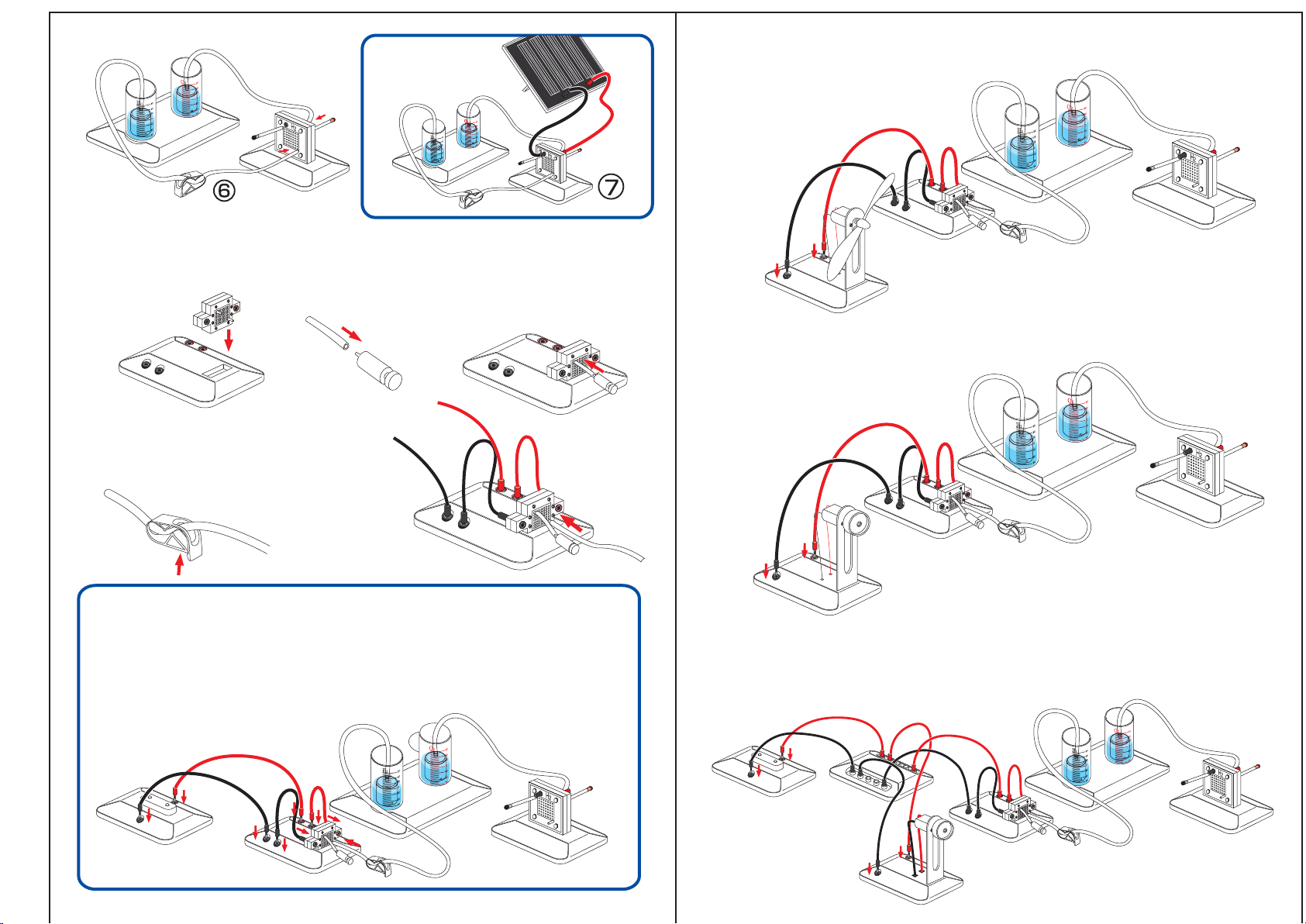
USING FUEL CELLS TO CONVERT HYDROGEN TO ELECTRICITY
Preparation of the Fuel Cell System
Insert the fuel cell into the base with the red terminal on the same side as the red terminals on the base.
Connect a green purging valve to one end of a 2cm tube and the other end to the upper nozzle on the hydrogen
side of the fuel cell.
Clench the tube connected to the electrolyzer and
hydrogen cylinder so that none of the hydrogen in the
cylinder from the last experiment can escape. Next
disconnect the tube from the electrolyzer and connect it
to the lower nozzle on the fuel cell.
Experiment 5: Using a PEM Fuel Cell to Power the Small Electric Fan Module
Repeat the hydrogen production and fuel cell
preparation steps.
Next, connect the small fan/wheel motor base to
the fuel cell base to generate power to the motor.
EXPERIMENT 5
Experiment 6: Using a PEM Fuel Cell to Power the Small Car Wheel Module
Repeat the hydrogen production and fuel cell preparation steps. Next,
connect the small fan/wheel motor base to the fuel
cell base to generate power to the motor.
Experiment 4: Using a PEM Fuel Cell to Power the LED Module
Connect the fuel cell to the fuel cell base using the red and black wires. Make sure to connect the
black wire with the black terminals and red with red terminals. Now connect the LED module to the
base in the same manner.
You should see the LED lights begin flashing. If not, purge a very small amount out of the valve to
allow some of the gas to move into the fuel cell. As the LED light consumes electricity the fuel cell
will consume hydrogen from the cylinder and you will see the water level reflect the changes in
amount of gases consumed.
EXPERIMENT 4
EXPERIMENT 6
Experiment 7: Using a PEM Fuel Cell to Power the Small Fan/Wheel Motor
Module and the LED Module in Parallel
Repeat the hydrogen production and fuel cell preparation steps. Next, connect the small
fan/wheel motor base and the LED module base to the circuit board. Then connect the circuit
board to the fuel cell module base to generate power to both modules in parallel.
EXPERIMENT 7
Page 3

DISCOVERING WIND ENERGY
Assembly of the Wind Turbine
Please refer to the WindPitch Education Kit Assembly Instructions included in your HydroWind Kit for
reference in assembling the Wind Turbine.
Below table indicates expected RPM speed, current, voltage, and power when placing the WindPitch in
constant windspeed of 10mph when connected to load of 50 Ohms. This level of resistance may be applied
using common potentiometer or Horizon’s variable resister module (included in Renewable Energy
Education Set- FCJJ-37)
Wind Kit Technical Specifications:
Blade Type
No. of Blade Wind Speed
Blade A
3 10 50 1.15 28 0.03 400
Blade B
3
Blade C
3
(mph)
10
10
Load
(Ohm)
50
50
Output Voltage
(V)
1.35
2.50
Output Current
(mA)
30
50
Output Power
(W)
0.04
0.125
Rotor Speed
(RPM)
490
705
Experiment 8: Using a Wind Turbine
to Power the LED Module
Power the LED module by attaching the
wind turbines cables to their respective
slots on the LED module base. Position
turbine to directly face the direction of wind
source.
EXPERIMENT 8
Experiment 9: Preparation of the Electrolyzer Module and Wind Powered
Hydrogen Production
Connect the red and black cables to the corresponding terminals located on
the wind turbine and reversible fuel cell. For best results using the WindPitch
to generate hydrogen using the included reversible fuel cell, setup the wind
turbine hub with (3) profiled blades supplied with the kit. Use combinations
of the A, B or C blades.
Set the blade pitch to 6 degrees. Make sure that the wind turbine is
generating AT LEAST 2.5 volts. If not, move the wind turbine closer
to the fan until it does. Also, make sure that the blade pitch is
between 10 and 15 degrees. The wind turbine is sensitive to this
setting at high wind speeds.
Allow the table fan and wind turbine to run for 60 minutes on
high wind speed setting to generate
sufficient amounts of
hydrogen and oxygen
EXPERIMENT 9
gases that are stored in
the water/gas tanks.
If the wind is sufficient the system will now start to produce
hydrogen and oxygen in the respective cylinders. When
bubbles begin to surface in the hydrogen cylinder the cycle is
Battery
Pack
complete. Disconnect the reversible fuel cell from the Wind
Turbine.
Procedure for repeated gas production: Disconnect the small plugs from the tubes connected to the
nozzles on the reversible fuel cell. This will allow water into the inner cylinders to replace the gasses and
reset water levels to “0” line. Re-insert the plugs into the tubes and repeat electrolysis again.
Note: You may also use the battery pack to perform electrolysis (In the case of no wind source)
Push and slide
open the cover
Experiment 10(alternative): Using the Battery Pack to Perform Electrolysis
(in the case of no sun or wind)
Please remove the screw from cover of battery box using a screw driver.
Push and slide the cover and open the battery box.
Try NOT to touch the cables when you open the cover.
Place two AA batteries as indicated.
Push and slide the battery box cover to closed position and screw fightly
into place using screw driver.
Remove the screw
from the cover
EXPERIMENT 10
Make sure the switch on the battery box is in the "off" position before you
place the batteries into the box.
WARNING: If the cable is short circuited the batteries inside could
become hot and potentially cause burns, melting of parts, or create
risk of fire.
Note: Battery’s energy may be consumed after 4-5 times of use.
AA Battery
AA Battery
Page 4

RENEWABLE ENERGY EDUCATION SET
TECHNICAL SUPPORT
1. The water levels do not drop when the gas outlet tubes on both sides of the fuel cell are unplugged.
Solution:
Check whether the holes on the wall of the inner container are blocked. If so, turn the inner container until water enters the holes and fills up the inner container.
2. The electrolyzer does not produce hydrogen and/or oxygen.
Solution 1:
Check whether the wires are appropriately connected, and whether there are any loose connections. The fuel cell could be completely destroyed if the red wire of the battery pack is connected to
the black jack of the fuel cell.
Solution 2:
Replace the old batteries with new one in the battery pack.
3. The load cannot work while there is hydrogen left in the inner container.
Solution:
Push the green purging valve to release tiny amount of hydrogen. You can then observe the load
working well again.
4. The water electrolysis process slows down.
Solution:
Inject water to the oxygen side of the fuel cell by using the syringe and wait for about 3 minutes
before using the electrolyzer again.
5. No hydrogen is produced using the windturbine outdoors.
Solution:
If the wind speed is not sufficient electricity will not be created. Use a common desk fan with faster
wind speed to perform the electrolysis using the electrolyzer, or conduct the experiment under
stronger wind conditions.
6. If the fuel cell and/or electrolyzer becomes flooded with water
Solution 1:
Use the syringe to clear the water out of the fuel cell.
Solution 2:
Use the hair drier to blow hot air towards the fuel cell and the nozzles on each side. Make sure you
blow warm air towards the fuel cell.
7. The fuel cell can not generate electricity while there is hydrogen still left in the hydrogen container.
Solution 1:
Push the purging valve to release remaining amounts of hydrogen.
Solution 2:
Use the syringe to clear the water out of the fuel cell.
 Loading...