

Page 1

BOOKLETMAKER
SPF-200A
/
FC-200A
SPF-200L
/
FC-200L
*UM201102*
BOOKLETMAKER
Important Information
• This manual is designed to help you to install, operate and maintain the
SPF-200A/SPF-200L or FC-200A/FC-200L Bookletmaker. Please read and
understand this manual, and keep it in a safe and convenient place.
• Do not operate the SPF-200A/SPF-200L or FC-200A/FC-200L until you read and
understand the instructions in this manual.
• Horizon International Inc. shall not be liable for incidental consequential
damages resulting from: improper or inadequate maintenance by the customer,
unauthorized modification or misuse, or operation outside of the environmental
specifications for the product.
• Horizon International Inc. pursues a policy of continuing improvement in design
and performance of the product. Therefore, the product design and
specifications are subject to change without prior notice and without our legal
obligation.
• All rights are reserved. No part of this manual may be photocopied, reproduced
or translated to another language without the prior written consent of Horizon
International Inc.
160218/SPF200A/FC200A/SPF200L/FC200L/20E/HN,TM,AT/F7/ICS5/PXI
This manual explains on the basis of the SPF-200A/FC-200A.
The operating instructions for the SPF-200L/FC-200L are added
as necessary.
In case that the sheet length is longer than 500 mm (19.68”),
some functions may not available in the upstream and downstream devices of the SPF-200L.
UM201102-20(000)
i
Page 2
Safety Precautions
Safety precautions are indicated in this manual as follows:
The term WARNING indicates a potentially hazardous situation which, if not
avoided, could result in death or serious injury.
The term CAUTION indicates a potentially hazardous situation which, if not
avoided, may result in serious injury, or damage to the machine.
This symbol indicates a note which includes important information. Follow
the note to operate the machine safely.
This symbol indicates a prohibited action. Do not perform any prohibited
action.
This symbol indicates an essential procedure. Follow the procedure to
operate the machine safely.
Important
Attention
Note
Additional
Information
• This lists the range of acceptable values and operating
conditions.
• This information will help you to avoid problems with the
machine or help you learn how to operate the machine.
• Refer to this note when you operate the machine.
• This explains a mechanism in the machine.
ii
Page 3

Operating Safety Precautions
WARNINGS for Operation
This machine must be operated by just one person at a time.
Work alone when you maintain and lubricate the machine. Letting someone else operate the
machine may cause severe personal injury.
Do not remove or bypass any safety features. Moving parts can cause severe personal
injury.
Some adjustments must be made with some of the machine covers opened.
Keep your hands and fingers outside of the safety cover and away from any moving parts
while the machine is running. Otherwise moving parts can cause severe personal injury.
The machine will not stop immediately if the Emergency Stop switch on an upstream device
is pressed. After all in-process booklets are delivered, the machine will stop.
Do not allow anyone else near the machine when you are moving the main section of the
SPF forwards or backwards.
When replacing the knife, wear gloves and do not touch the edge of the knife directly. The
knife is extremely sharp, and may cause severe personal injury.
Press the Emergency Stop button before turning the handwheel. A sudden accidental start
of the machine can cause severe personal injury.
Do not operate the fore-edge trim section separately from the SPF main unit.
CAUTIONS for Operation
After turning off the power switch, wait ten seconds before turning it on again. Otherwise, a
circuit board may be damaged.
The fold knife and roller may strike each other if the fold knife is lifted too far. Turn the fold
knife height adjustment knob in small amounts.
Remove the cable connected to the SPF main unit before moving the fore-edge trim section
away.
iii
Page 4

WARNINGS for Maintenance
Turn off the power switch before beginning any maintenance operation. If the machine accidentally starts suddenly, this can cause severe personal injury.
Turn off the power switch before clearing a jam. If the machine accidentally starts suddenly,
this can cause severe personal injury.
When working inside the machine, be careful to keep your hands away from nearby parts.
Be sure to press the Emergency Stop button before opening the fold section cover. The
machine may start suddenly, causing severe personal injury.
Turn off the power switch before resetting a circuit breaker. Otherwise, the machine may
start suddenly, causing severe personal injury.
Fuse replacement must be done under the supervision of a maintenance administrator.
Turn off the power switch and unplug the power cable before replacing a fuse.
When the booklet thickness detector is installed, evacuate the laser unit.
Otherwise the sensor may be damaged.
CAUTIONS for Maintenance
Use the types of lubrication oil and grease which are recommended by HORIZON. Other oil
or grease may reduce the life of the machine or cause damage.
WARNINGS for Installation
Turn off the main power or circuit breaker in the factory before connecting the power cord to
the machine. High voltage electricity can cause severe personal injury.
CAUTIONS for Installation
Be sure to install the floor mounting plates to keep the machine level. Otherwise, vibration
may cause the machine to move. The binding quality may deteriorate, or the machine may
be damaged.
The SPF-200A +the FC-200A weigh about 720 kg (1590 lb). The SPF-200L +the FC-200L
weigh about 750 kg (1653 lb). Transport and install the machine safely, and keep the weight
of the unit in mind.
Install the machine correctly, referring to the installation manual or installation instructions in
the user’s manual before starting the machine. Otherwise, the binding quality cannot be
guaranteed.
iv
Page 5

CONTENTS
Important Information ............................................................................................................... i
Safety Precautions ...................................................................................................................ii
Operating Safety Precautions .................................................................................................iii
1 Machine Description
1-1 Automatic and Manual Settings ................................................................................. 1
1-2 Machine Descriptions .................................................................................................. 2
1-2-1 Safety Device / Safety Functions ......................................................................... 2
1-2-2 Overall Machine ................................................................................................... 3
1-2-3 Manual Feed / Infeed Conveyor Section ............................................................. 5
1-2-4 Infeed Section ...................................................................................................... 6
1-2-5 Jog Section .......................................................................................................... 7
1-2-6 Stitch Section ....................................................................................................... 8
1-2-7 Fold Section ......................................................................................................... 9
1-2-8 Fore-edge Trim Section ..................................................................................... 10
1-2-9 Delivery Conveyor ............................................................................................. 11
1-2-10 Control Panel ................................................................................................... 12
1-3 Screen Descriptions .................................................................................................. 13
1-3-1 Setting-Binding Pattern Screen ......................................................................... 13
1-3-2 Setting-Sheet Size Screen ................................................................................ 13
1-3-3 Setting-Finishing Size Screen ........................................................................... 14
1-3-4 Setting-Instruction Screen ................................................................................. 15
1-3-5 Setting-Confirmation Screen ............................................................................. 19
1-3-6 Binding-Operation Screen ................................................................................. 20
1-3-7 Binding-Fine Adjust Screen ............................................................................... 22
1-3-8 Binding-Status Setting Screen ........................................................................... 24
1-3-9 Memory Screen ................................................................................................ 28
1-3-10 Information-Main Screen ................................................................................ 29
1-3-11 Information-Monitor/Single Operation Screen ................................................ 30
1-3-12 Information-Administrator Screen .................................................................... 31
1-3-13 Error Screen .................................................................................................... 34
2 Checks before Operating
2-1 Checking the Emergency Stop Function ................................................................. 35
3 Operating Procedures
3-1 Overview of Operating Procedures .......................................................................... 37
3-2 Setting Up a Job Using the Setting Screen ............................................................. 39
3-3 Doing a Changeover .................................................................................................. 44
3-3-1 Removing Parts Before the Changeover ........................................................... 44
3-3-2 Attaching Parts After Changeover ..................................................................... 49
3-3-3 Confirmation After Changeover ......................................................................... 52
3-4 Doing a Test Binding ................................................................................................. 53
3-4-1 Preparing the Upstream Device ........................................................................ 53
3-4-2 Binding a Booklet as a Test ............................................................................... 55
3-4-3 Do a Test Binding and Check the Settings ........................................................ 56
3-4-4 Perform the Test Stitching ................................................................................. 59
3-5 Confirming the Status Settings ............................................................................... 60
v
Page 6

3-6 Start Binding .............................................................................................................. 62
3-7 Manual Feeding .......................................................................................................... 65
3-8 Saving, Loading and Deleting Jobs ......................................................................... 70
3-8-1 Saving a Job ...................................................................................................... 70
3-8-2 Loading a Job .................................................................................................... 71
3-8-3 Deleting a Job .................................................................................................... 73
3-9 Power Saving Mode ................................................................................................... 74
3-10Reversing the Stitcher Heads ................................................................................... 75
4 Adjustments
4-1 Stitch Adjustments ................................................................................................... 77
4-2 Infeed Section Adjustments ...................................................................................... 79
4-3 Jog Section Adjustments .......................................................................................... 81
4-4 Fold Section Adjustments ......................................................................................... 83
4-5 Fore-edge Trim Section Adjustments ...................................................................... 84
5 Troubleshooting
5-1 If an Icon Is Displayed on the Error Screen ............................................................. 87
5-1-1 If An Error Icon Is Displayed .............................................................................. 87
5-1-2 If a System Error Occurs ................................................................................... 90
5-2 Removing Jammed Sheets ....................................................................................... 99
5-3 Stitch-Related Problems ......................................................................................... 101
5-3-1 The Stitches Are Moved Parallel to the Fold Line ........................................... 101
5-3-2 The Distance Is Not Correct ........................................................................... 101
5-3-3 The Stitches Are Angled................................................................................. 101
5-3-4 The Stitch Position Varies............................................................................... 102
5-3-5 The Stitches Are Curved................................................................................. 102
5-3-6 There Are Problems With The Stitch Length.................................................. 102
5-3-7 The Sheets Are Not Stitched.......................................................................... 103
5-3-8 The Wire Jams................................................................................................ 103
5-3-9 The Shape of the Stitch is Incorrect................................................................ 104
5-4 Poor Sheet Arrangement ......................................................................................... 107
5-5 Folding-Related Problems ...................................................................................... 109
5-5-1 Fold Skewing.................................................................................................. 109
5-5-2 The Folding Position Varies............................................................................ 109
5-5-3 Failed to Fold at Correct Position ................................................................... 110
5-5-4 Jog Error Not Detected...................................................................................111
5-5-5 The Sheets Are Bent ...................................................................................... 111
5-6 Fore-edge Trimming-Related Problems ................................................................. 112
5-6-1 The Sheets Are Trimmed Incorrectly.............................................................. 112
5-6-2 Incorrect Trim Position.................................................................................... 112
5-7 Scratched Sheets ..................................................................................................... 113
5-8 Specific Symptom-Related Problems .................................................................... 114
5-8-1 The Buzzer Beeps at an Interval of Two Seconds.......................................... 114
5-8-2 Fine Adjustment from the Touch Panel Does Not Work................................. 114
5-8-3 The Delivery Conveyor Does Not Move ......................................................... 114
5-8-4 The Trim Is Not Collected (The pump does not operate) ................................ 114
5-8-5 The Touch Panel Does Not Light Up.............................................................. 115
5-8-6 A Stitcher Head is Jammed............................................................................115
vi
Page 7

5-9 Other Problems ........................................................................................................ 116
5-9-1
The Booklets Overlap Each Other at the Delivery Conveyor though They are Offset.... 116
6 Maintenance
6-1 Loading Stitch Wire ................................................................................................ 117
6-2 Threading the Wire Through the Stitcher Head .................................................... 118
6-3 Attaching the Transport Pusher ............................................................................. 119
6-4 Lubrication ............................................................................................................... 120
6-4-1 Top and Bottom Guide Slide Shaft .................................................................. 120
6-4-2 Stitcher Vertical Slide Shaft ............................................................................. 120
6-4-3 Fold Knife Section ........................................................................................... 120
6-4-4 Stitcher Head ................................................................................................... 121
6-4-5 Clincher Drive Cam ......................................................................................... 121
6-5 Cleaning ....................................................................................................................122
6-5-1 Around the Stitcher Heads .............................................................................. 122
6-5-2 Transport Belts / Transport Rollers .................................................................. 122
6-5-3 Sensors ........................................................................................................... 123
6-6 Replacing the Fore-edge Trim Knife ...................................................................... 125
6-6-1 Upper Knife Replacement ............................................................................... 125
6-6-2 Lower Knife Replacement ............................................................................... 127
6-7 Clincher Point Replacement ................................................................................... 130
6-8 Guide Sheet Replacement ....................................................................................... 131
6-9 Stitcher Head Removal / Attachment ..................................................................... 132
6-9-1 Stitcher Head Removal .................................................................................... 132
6-9-2 Stitcher Head Attachment ................................................................................ 132
6-10Resetting the Circuit Breakers ............................................................................... 136
6-11Replacing the Fuses ................................................................................................ 137
7 Installation
7-1 Installing the Main Unit ............................................................................................ 139
7-2 Installing the Fore-edge Trim Section .................................................................... 141
7-3 Attaching the Accessories ...................................................................................... 143
7-4 Installing the Delivery Conveyor ............................................................................ 145
7-4-1 SC-200 Short Conveyor .................................................................................. 145
7-4-2 LC-200 Long Conveyor ................................................................................... 146
7-5 Connecting to an Upstream Device ....................................................................... 147
7-6 Checking ROM Versions of Connected Devices ................................................... 150
7-7 Connecting the Main Unit Power Cable ................................................................. 152
7-8 Setting the System Configuration .......................................................................... 153
7-9 Setting Up for Optional Devices ............................................................................. 154
7-10Synchronizing Between the Devices ..................................................................... 155
8 Options
8-1 Preset Kicker PK-30 ................................................................................................. 157
8-1-1 Installation of Preset Kicker ............................................................................. 157
8-1-2 Operation ......................................................................................................... 158
8-2 Paper Insertion Kit PN-200 ...................................................................................... 159
8-2-1 Operation ......................................................................................................... 159
8-2-2 Installation of Paper Insertion Kit ..................................................................... 161
8-3 Four Stitching Kit FST-200 ...................................................................................... 166
vii
Page 8

8-3-1 Accessories for Four Stitching Kit................................................................... 166
8-3-2 Installation of Clincher ..................................................................................... 168
8-3-3 Installation of Stitcher Head ............................................................................. 169
8-3-4 Wire Attachment .............................................................................................. 171
8-3-5 Option Setup .................................................................................................... 173
8-3-6 Limitation for Use ............................................................................................. 174
8-4 Side/Corner Stitch Kit SSK-200/SSK-200L ............................................................ 175
8-4-1 Installation of Side/Corner Stitch Kit............................................................... 175
8-4-2 Option Setup................................................................................................... 178
8-5 Mis-stitch Detector SDS-200 ................................................................................... 179
8-5-1 Installation of Mis-stitch Detector ..................................................................... 179
8-5-2 Operation........................................................................................................182
8-6 Thickness Detector TD-200 ..................................................................................... 183
8-6-1 Installation of Thickness Detector .................................................................... 183
8-6-2 Calibrating the TD-200.................................................................................... 185
8-6-3 Operation ......................................................................................................... 187
8-7 Chip Extractor TB-200 ............................................................................................. 189
8-7-1 Operation ......................................................................................................... 189
8-7-2 Installation of Chip Extractor ............................................................................ 190
8-8 Loop Stitching .......................................................................................................... 192
8-8-1 Loop Stitcher Head Replacement .................................................................... 192
9 Appendix
9-1 Specifications ........................................................................................................... 195
9-1-1 SPF-200A....................................................................................................... 195
9-1-2 FC-200A ......................................................................................................... 198
9-1-3 SPF-200L........................................................................................................ 199
9-1-4 FC-200L.......................................................................................................... 203
9-2 Accessories .............................................................................................................. 204
9-2-1 SPF-200A/SPF-200L ....................................................................................... 204
9-2-2 FC-200A/FC-200L .......................................................................................... 206
9-2-3 IFU-200 ............................................................................................................ 207
9-3 Consumables ........................................................................................................... 208
viii
Page 9
s
11119
10101A1
Front Transport Belt Gap Adjustment
Transport Belt Height Adjustment
Stopper Position
Fold Roller Gap
Jog Pusher
Fold Section Top and Bottom Guide Width
Fold Section Top and Bottom Guide Stroke
Forward Roller Position
Delivery Roller Position
Saddle Stitch Stopper Replacement
(Large / Small)
Saddle Stitch Stopper Position
Guide Bar Attachment
Transport Pusher Speed
Corner Stitch Guide Replacement
Top and Bottom Guide Width
Top and Bottom Guide Stroke
Jogging Frequency
Manual Feed Guide Width
Fore-edge Trim Section
Alignment for a Small Booklet
Buckle Gap Adjustment
Fold Skew Correction
Fold Knife Height Adjustment
Infeed Section Direction
Stitcher Head Drive Block Attachment
Stitch Angle
Stitch Distance
Stitch Length
1 Machine Description
This chapter explains how to use the automatic and manual settings, and describes the
parts of the machine and their functions.
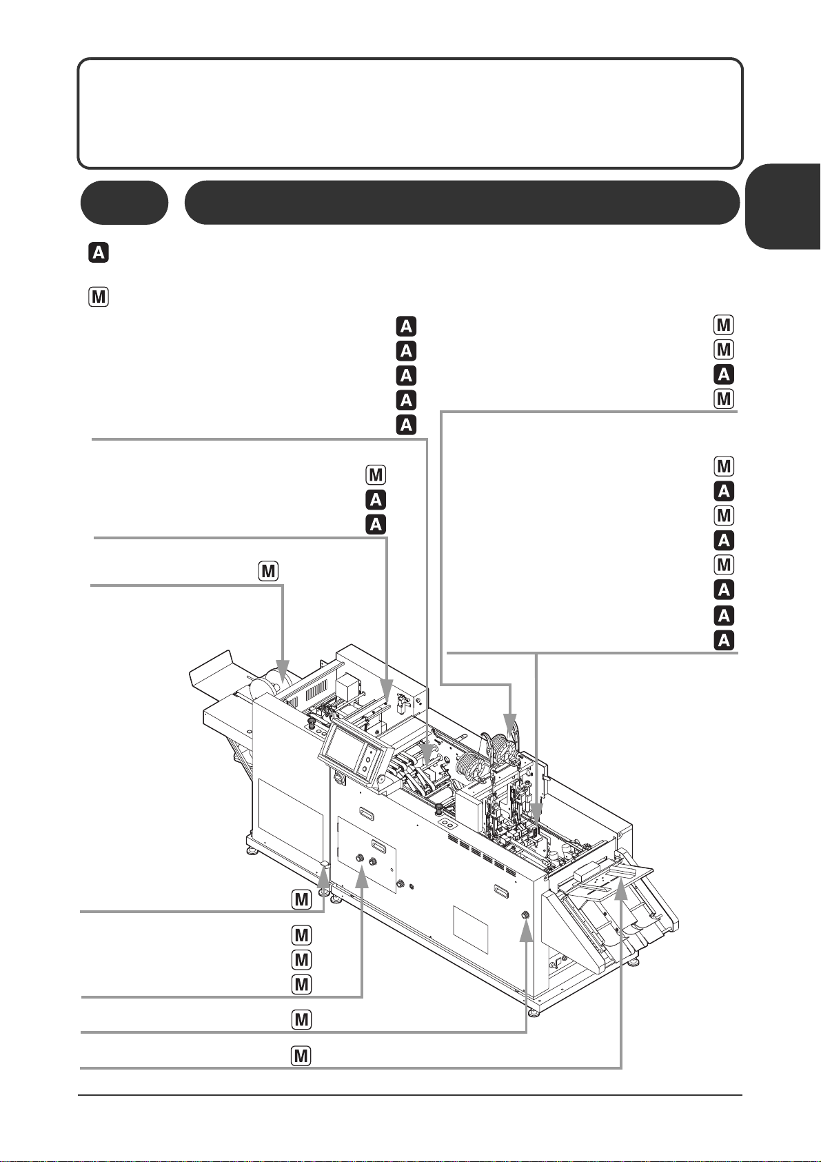
1-1 Automatic and Manual Settings
Automatic: This indicates a setting which is performed automatically to match the sheet size and
binding pattern. The setting can be changed using the touch panel.
Manual: This indicates a setting which is performed manually using a knob or lever.
1
Machine Description
Automatic and Manual Settings /
1
Page 10
11119
10201A1
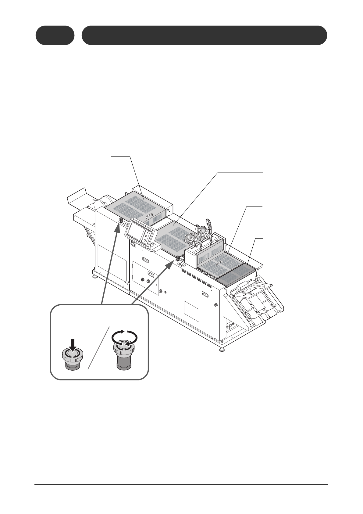
Jog Section
Cover
Fore-edge Trim Section
Cover
Infeed Section
Cover
Emergency Stop Button
Press
Release
Fold Section
Cover
1-2-1
1-2 Machine Descriptions
Safety Device / Safety Functions
1-2-1 Safety Device / Safety Functions
The whole system stops when a safety cover is opened or the Emergency Stop bottom is pressed during operation.
2
Page 11
21102
10202A1
11119
10202D1
11119
10202B1
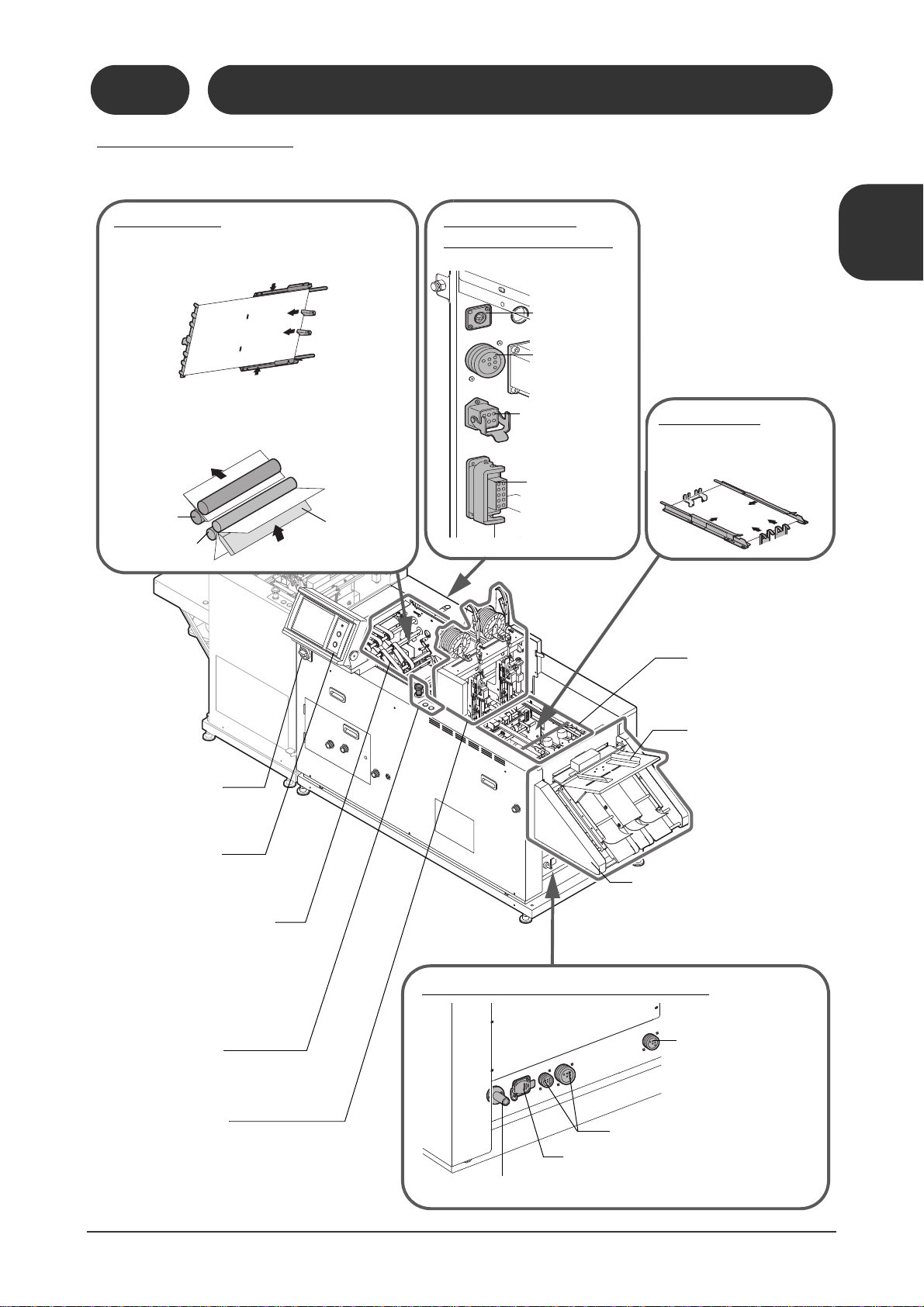
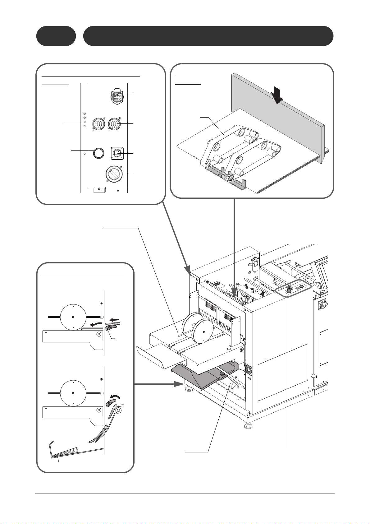
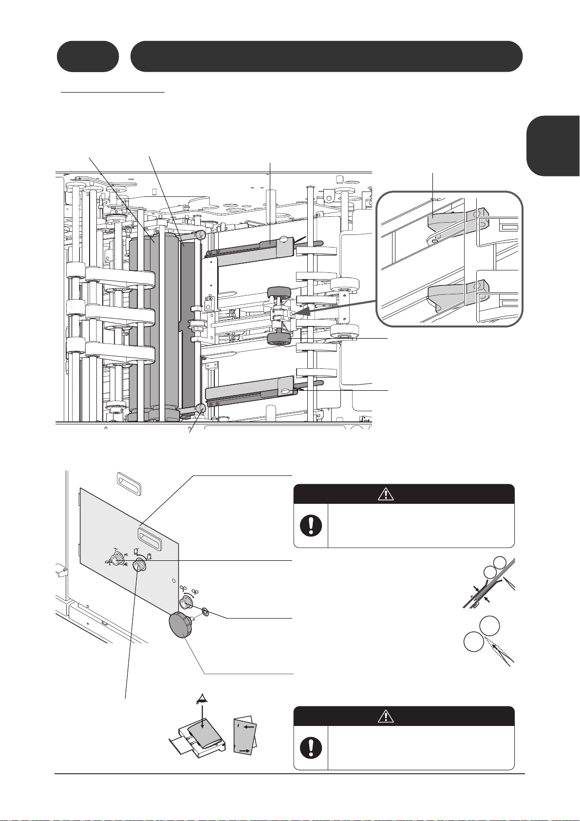
Fold Section
Connectors for Upstream Devices
2. The sheet is pushed up by the fold knife, then is
caught in the fold roller and folded. Next the press
rollers crease the folded sheet.
Power Switch
Control Panel
Refer to 1-2-10.
Horizontal Transport
Section
The unfolded sheets are
transported through this section.
Stitch Section
Control Panel
1. The sheet is squared-up in the top-bottom and
fore-edge directions before folding. (This happens if the top and bottom guide jog function is
turned on.)
Infeed Section
The sheets are transported from this section to
the jog section.
Manual Feed Section
The sheets can be manually fed when the stopper
opens in this section.
Press
Rollers
Fold Rollers
Fold Knife
Air Line from the Collator
Not Used
Signal Connectors for Collator
Signal Connector for
IFU-200 Infeed Conveyor
Stitch Section
The sheets are stapled here.
11119
10202C1
Jog Section
The sheet is squared-up in
the top-bottom and fore-edge
direction before stitching.
Connectors for
Downstream Device
Power Connector
for Fore-edge Trim
Connector for Delivery Conveyor
Signal Connector
for Fore-edge Trim
Section
Arcnet Communication Connector
Optional IFU-200
Infeed Conveyor
The collated sheets are transported
from the collator to the infeed section
of the SPF-200A/200L.
1-2-2
1-2 Machine Descriptions
Overall Machine
1-2-2 Overall Machine
This explains how to use the system configuration including the optional IFU-200 infeed conveyor, FC200A/200L fore-edge trim section, and the SC-200 delivery conveyor.
1
11119
10202J1
Machine Description
Machine Descriptions /
11119
10202E1
3
Page 12
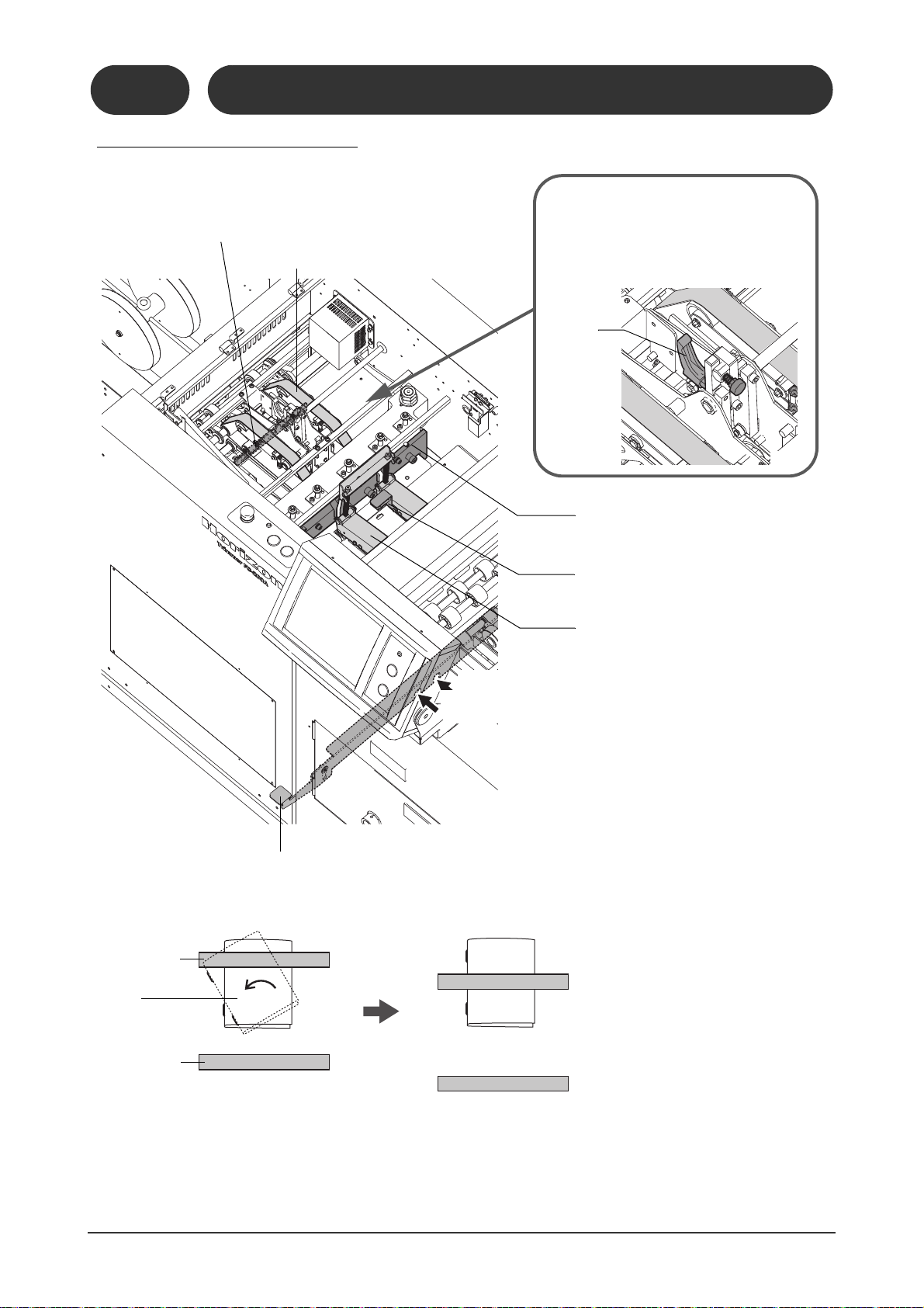
1-2 Machine Descriptions
Fore-edge Trim
Section
The transport belts compress the booklets, and
then the fore-edge of
each booklet is trimmed.
Connectors for Downstream
Devices
Connector
for TB-200
Chip
Extractor
Fore-edge Trim Section
Control Panel
Transport
Belt
Not Used
Hole for MKU54, MKU-54T or
PST-40 Communication
Cable
Delivery Conveyor
(Option)
This illustration shows a short conveyor.
Connector
for PK-30
Preset
Kicker
Power Connector for
Delivery Conveyor
Faulty Set Ejecting Section
A faulty set is ejected to the faulty set
ejecting tray.
Good
Set
Bad
Set
Gate
Faulty Set Ejecting Tray
Trim Chute
The trim is ejected from this chute.
Not Used (for
Short Circuit
Connector)
1-2-2
Overall Machine
11119
10202H1
11119
10202G1
4
11119
10202I1
11119
10202F1
Page 13

1-2 Machine Descriptions
Manual Feed Stopper
Sheets can be fed manually if the stopper is lowered.
Manual Feed Sheet Sensor
This sensor detects any sheets placed on the manual
feed table.
Manual Feed Guide
This guide can be set to match the width of the sheet
being fed.
Guide Position Scale
Sheet Sensor
This sensor detects a sheet as it feeds from the collator and triggers the manual feed.
Upper Transport Section Lifting
Handle
1-2-3 Manual Feed / Infeed Conveyor Section
1-2-3
Manual Feed / Infeed Conveyor Section
1
Machine Description
11119
10203A1
Machine Descriptions /
5
Page 14
1-2 Machine Descriptions
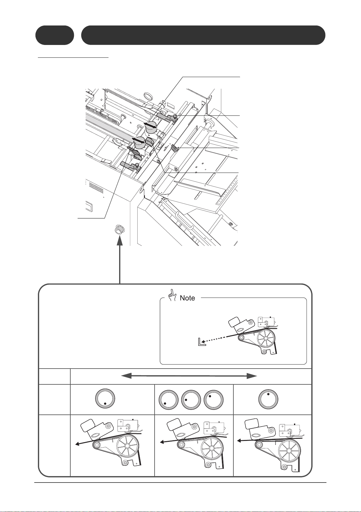
Infeed Section Direction
Adjusting Knob
There are five possible settings. To make an adjustment, pull the knob and turn it.
Sheet
Length
Short Long
Knob
Position
Infeed
Direction
In the ideal setting, the sheet is directed toward the corner of the stopper.
11119
11119
10204B1
Low
Middle
High
(Horizontal)
Weights
The transport roller pressure can be
adjusted by changing the positions of
these weights. To move a weight, turn
the top to loosen it.
Hold-down Guides
These guides help to control sheets
which are bent or rolled.
Fore-edge Jog Plate
This squares up the sheet in the foreedge direction.
Jam Sensor
Sheet Holder
If the tail of the sheet remains at
the exit of the infeed section and
is not transported completely, the
sheet can be pushed to the belt
using this holder. (If the holder
pushes too strongly, the sheet
may be scratched.)
1-2-4 Infeed Section
1-2-4
Infeed Section
11119
10204F1
11119
10204G1
11119
10204A1
11119
10204E1
6
11119
10204C1
11119
10204D1
Page 15
1-2 Machine Descriptions
21102
10205A1
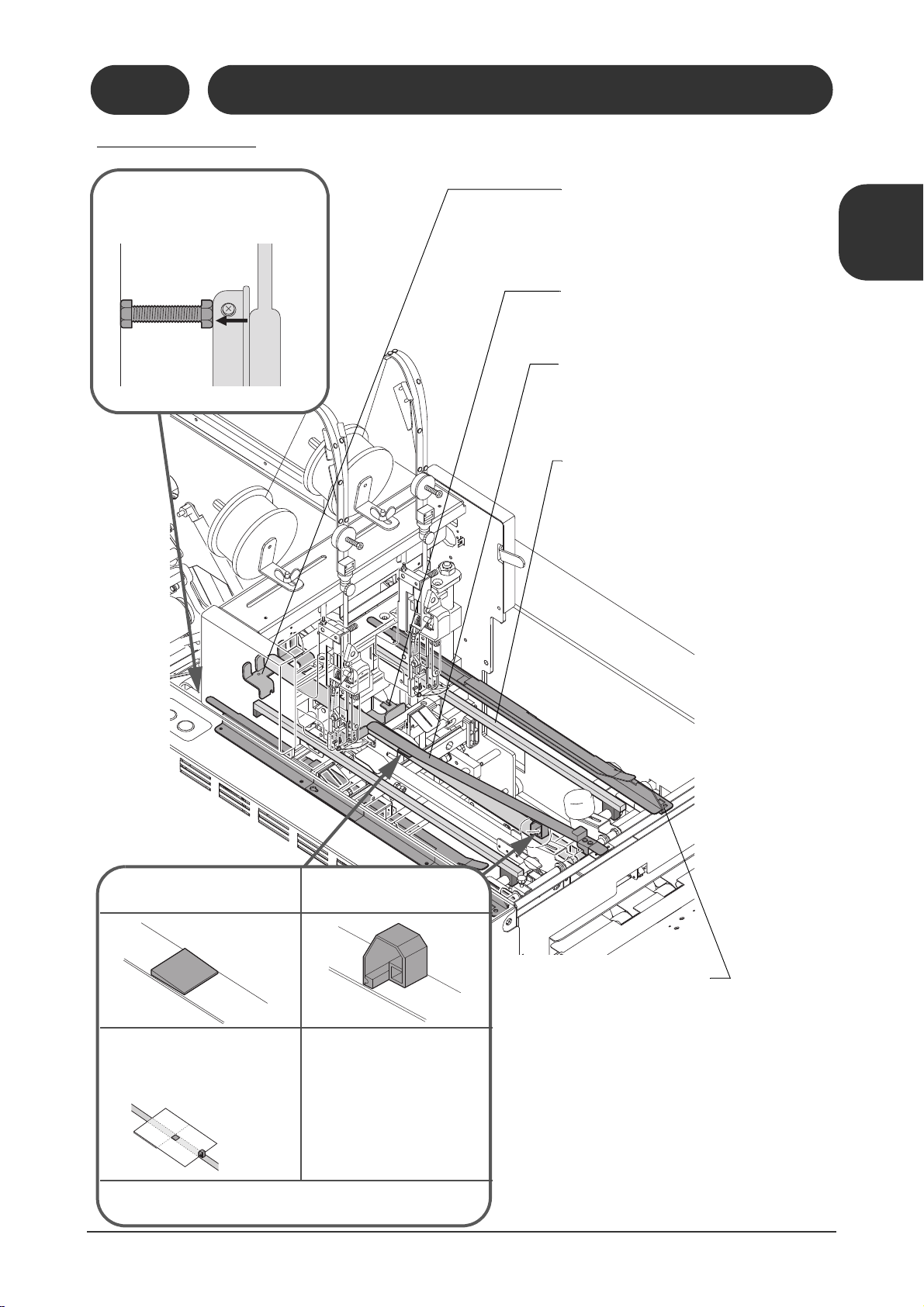
Transport Pusher for
Paper Insertion (Option)
Transport Pusher
This pusher transports the flat
sheet when it is inserted into the
center page of a stitched booklet.
The sheet is pushed and transported by this pusher. The
pusher may be removed if there
are paper jams. (Remember to
re-install the pusher for normal
setups.)
The waiting position for the transport pusher can be adjusted using
the touch panel screen. Refer to page 25 for details.
11119
10205C1
Saddle Stitch Stopper
Install large or small stoppers to match the sheet
width. (The instruction screen is displayed on the
touch panel.)
Side Stitch Stopper
This stopper is used for side stitching and corner
stitching.
Top and Bottom Guides
- These guides jog the sheets from the top and bottom sides before stitching.
- The settings listed below can be done using the
touch panel.
- Jogging frequency before stitching
- Stroke (Guide opening when the sheet comes in)
- Delivery Stroke (Guide opening when the sheet
goes out)
- When you are doing corner stitching, these guides
are replaced by the corner stitch guide.
- This guide assembly consists of three parts. When
you are running small booklets, you may have to
remove these guides. (The instruction screen is
displayed on the touch panel.)
Side Stitch Sheet Hold-Down Plate
This plate prevents the sheets from floating.
Long type and short plates are available.
Guide Bar
This bar prevents the sheets from being bent
down. You must remove this bar before doing a
changeover. (The instruction screen is displayed
on the touch panel.)
Parallel Adjusting Bolt
This bolt is used as a gauge to adjust the
top-bottom guide so that it is parallel.
1-2-5 Jog Section
11119
10205B1
1-2-5
Jog Section
1
Machine Description
Machine Descriptions /
11119
10205D1
11119
10205E1
7
Page 16
1-2 Machine Descriptions
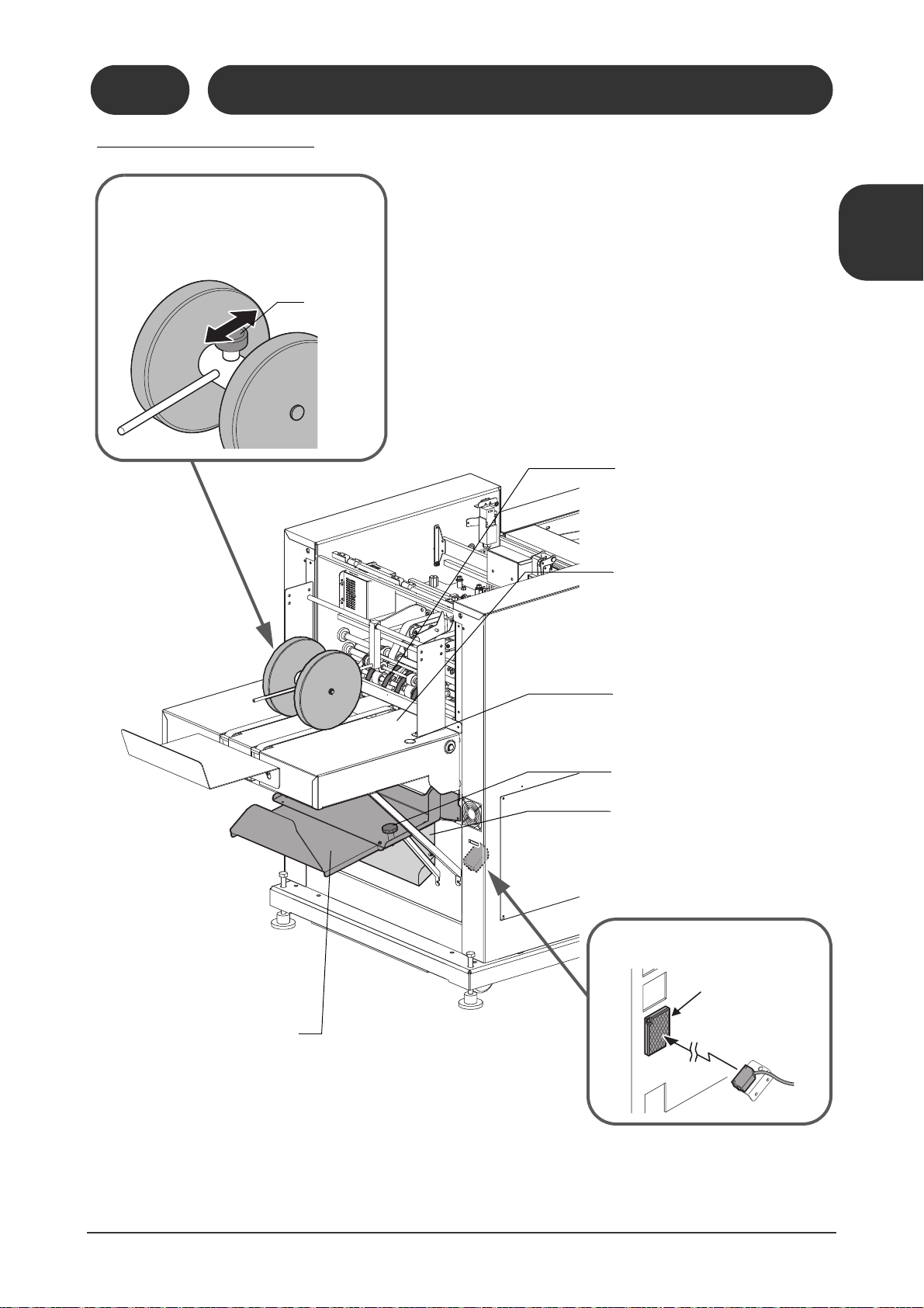
11119
10206D1
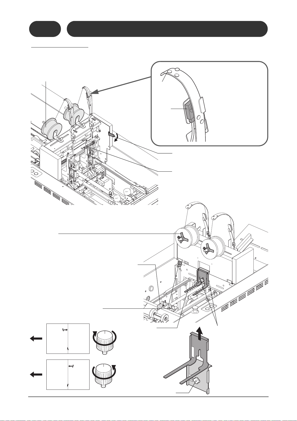
Wire Feeding
Detection Sensor
As the wire is feeding, the
wire guide bends down and
immediately returns to its
original position. This sensor
watches the movement of the
wire guide to see that the
wire is feeding properly. The
sensor is turned on (red LED
lights) when the wire guide is
bent down.
Clincher Lever
This allows you to remove a stitch which remains in
the clincher section.
Stitcher Head Drive Block
When one of these blocks is removed, the machine
does not make stitches on that side. The block on
the non-stitched side should be removed when you
are doing corner stitching. (The instruction screen
is displayed on the touch panel.)
Coil Brake
This brake prevents the coil from turning too easily and tangling
the wire. If the brake is pressed harder against the coil, it becomes
harder to turn the coil.
Stitch Angle Adjusting Knob
The stitch angle can be adjusted using this knob if one
stitch is not lined up.
Wire Coil
Standard wire is No.25 (0.5 mm in diameter)
Optional wire No.26 (0.45 mm in diameter) is
available.
Wire
Guide
Red LED
This lamp lights
when the sensor
detects the wire
guide.
There are circuit breakers inside this cover. See Section 6-10.
These holes allow for
installation of two
optional stitcher heads.
The positions of these
two stitchers are fixed.
Sheet Holder
This holder prevents the sheet from
floating. Long, short, and side stitching holders are available. Select the
holder to match the binding pattern
and sheet size. To change the holder,
loosen the locking knob. Set the
position of the holder to match
the thickness of the booklet.
Locking Knob
1-2-6 Stitch Section
The operation of the stitcher head is explained in Section 4-1.
Stitch Section
11119
10206C1
1-2-6
11119
10206A1
11119
10206B1
8
11119
10206E1
Page 17
1-2 Machine Descriptions
Fold Knife Height Adjusting Knob
The fold knife lifts when you turn this knob clockwise. (If you lift the fold knife too far, it may hit the
fold roller.)
Press
Rollers
These rollers
compress the
booklets.
Fold Rollers
The gap between the rollers
is automatically set to match
the booklet thickness
entered on the touch panel.
Fold Section Top and Bottom Guides
-These guides jog the sheets before folding.
-The settings listed below can be done using the touch panel.
- Distance between guides when jogging sheets
- Stroke (Guide opening when the sheet comes in)
- Delivery stroke (Guide opening when the sheet
goes out)
Fold Section Jog Pushers
-These pushers jog the sheets
before folding.
-The positions of these pushers
when jogging the sheets can be
adjusted on the touch panel.
(Refer to 1-3-7.)
Sheet Hold-Down Plate
These plates prevent the sheets from
floating.
Sheet Guide Locking Knobs
If sheets jam between the fold rollers and press rollers, remove the sheet guide by loosening these knobs.
Fold Skew Correction
Knob
As shown in the illustration, any
fold skewing can be corrected
by turning this knob clockwise.
Buckle Gap Adjusting Knob
The buckle gap can be adjusted in three levels
to match the sheet thickness.
The fold section stopper can be reached by opening this cover.
Press the Emergency Stop button before
turning the handwheel. A sudden accidental start of the machine can cause severe
personal injury.
WARNING
Do not open this cover while the machine
is running. Otherwise, moving parts can
cause severe personal injury.
WARNING
Forward Rollers
These rollers transport the sheets to
the fold section and prevent the sheets
from bouncing.
Handwheel
The fold roller and press rollers can be turned by hand for cleaning.
1-2-7 Fold Section
1-2-7
Fold Section
11119
10207B1
11119
10207A1
1
Machine Description
Machine Descriptions /
11119
10207F1
11119
10207E1
11119
10207D1
9
Page 18
1-2 Machine Descriptions
11119
10208A1
Booklet Stopper
This stopper is automatically
set to match the finishing size
of the booklet.
Transport Belts
The sheet is transported by these belts.
The gap between the upper and lower
belts is automatically set up to match the
book thickness entered on the touch panel.
Locking
Lever
Front Transport Belt Height
Adjusting Knob
If the booklets do not move correctly, adjust
this knob. To reduce the gap at the front of the
transport belts, loosen the locking lever and
turn the knob clockwise.
Jam Sensor
Trim Knife (Upper Knife)
Infeed Belts
These belts move the sheet into the foreedge trim section.
Fore-edge Trim Section Locking Lever
If you are trimming small booklets (smaller than B5), the booklet may not move correctly if the pressure is
different at the front and rear transport belts.
Transport Belt
Transport Belt
Lift the locking lever up and
move the fore-edge trim mechanism to the front.
When the fore-edge trim mechanism is moved to the front, the stopper holds the far side of the booklet,
and the booklet should stop straight against the stopper.
(The instruction screen for this is displayed on the touch panel when binding sheets smaller than B5.)
Position for Small Booklet
Normal Position
Stopper
1-2-8 Fore-edge Trim Section
1-2-8
Fore-edge Trim Section
11119
10208B1
10
11119
10208C1
Page 19
1-2 Machine Descriptions
11119
10209A1
Faulty Set Ejecting Gate
If the machine detects a faulty set, this
gate moves and the faulty set is delivered to the faulty set ejecting tray.
Delivery Conveyor
When a booklet is delivered, the belts
move for a moment. The running time
for the belts can be set on the touch
panel.
Delivery Rollers
These rollers hold the delivered booklet. These
rollers should be placed about 30 mm (1.2")
from the end of the booklet.
Locking Knob
Locking Knob
Jog Button
The conveyor belts move when this
button is pressed.
Faulty Set Ejecting Tray
When the faulty set eject function is activated on the touch
panel, faulty sets are delivered to this tray.
The possible causes of faulty sets are:
- Mis-feed / double feed / Jam in upstream device
- Fold section jog error
- Missed stitch detection (option)
- Fore-edge trim section thickness detection (option)
If the operation starts with a sheet remaining in the machine,
the sheet is delivered to this tray.
Trim Chute
The trim is ejected through this chute.
Trim Full Sensor
This sensor detects the trim full error.
Mirror
1-2-9 Delivery Conveyor
1-2-9
Delivery Conveyor
1
Machine Description
Machine Descriptions /
11
Page 20
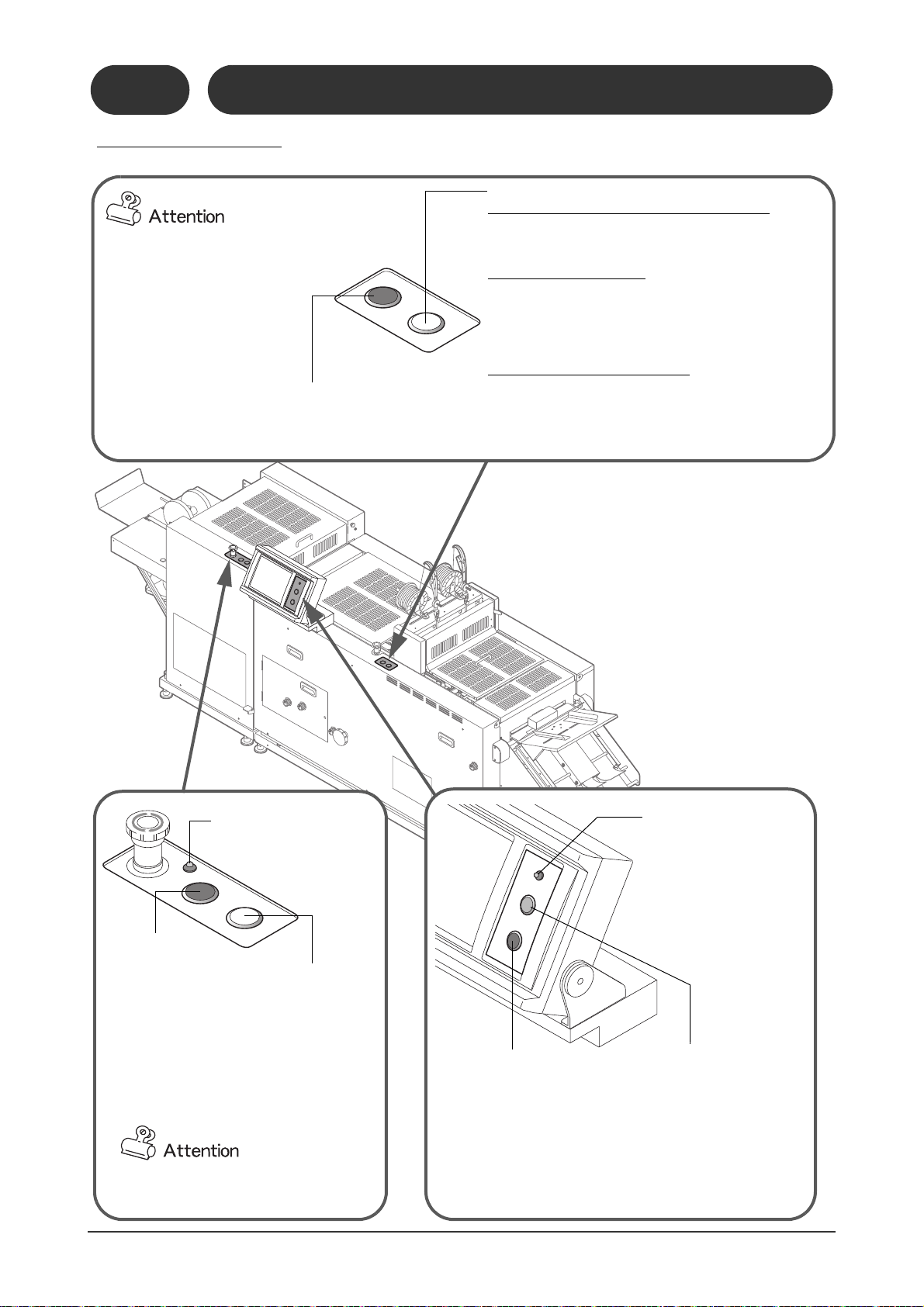
1-2 Machine Descriptions
11119
10210C1
Fore-edge Trim
Section Power LED
Trim Knife
Reverse Jog
Button
When this button is
pressed and held, the trim
knife operates once and
then stops at the top position. If the knife is locked,
the trim knife can be
returned to the top position using this button.
When some screens are displayed on
the touch screen, these buttons will not
work.
Stop Button
This button stops the binding
operation. Feeding from the
upstream device stops when
this button is pressed. All booklets in-process are delivered,
and the transport rollers keep
moving. When this button is
pressed again, the machine
stops completely.
Main Machine Power
LED
This LED lights when the
power switch is turned On.
The LED blinks if the machine
is using the power saving
mode.
Transport Belt
Inching Button
The transport belt at
the fore-edge trim section drives only while
this button is pressed.
Start Button
This button starts the binding operation. If there are sheets remaining
inside the machine, they will be
ejected. While this is happening,
the button blinks. When the
machine is ready, the button lights
and feeding from the upstream
device (collator) starts.
Machine Jog Button
This jogs the jog section and the fold section. Jogging is stopped when this button is pressed again.
This button will work even if a cover is opened.
Stitch Jog Button
Operating the stitcher heads in the normal direction
Press and hold this button to make one stitch in the normal
direction while the cover is closed and the Emergency Stop
button is not pressed.
Reversing the stitcher heads
The stitcher heads will return to the original position by
reverse movement if you press this button while pressing
the Machine Jog button when the cover is closed and the
Emergency Stop button is not pressed. See page 75 for
details.
Releasing the top and bottom guides
The top and bottom guides move outward if this button is
pressed while the cover is opened or the Emergency Stop
button is pressed. Any sheets remaining at the jog section
can be removed easily. (The top and bottom guide returns to
its setting position when the jog button is pressed.)
When the power is first turned on,
these buttons will not work until the
first changeover has been done.
1-2-10 Control Panel
11119
10210B1
1-2-10
Control Panel
12
11119
10210A1
11119
10210D1
Page 21

1-3 Screen Descriptions
21102
10301A1
- After the power is turned on, the Initial Screen and Binding
Pattern Screen are displayed.
- The binding pattern can be selected on this screen. Press
one of the icons, and the Sheet Size screen shown below
is displayed.
If the SSK-200A or the SSK-200L has been selected on the
Administrator Mode-Option Screen, these icons are active.
Binding Pattern Screen
OK
21102
10302A1
21102
10302B1
Sheet Size-Saddle Stitch Screen
Sheet Size-Side Stitch Screen
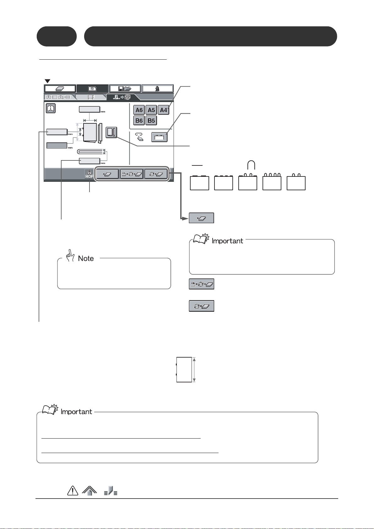
The dimensions are entered in steps of 0.1 mm (0.005").
Sheet Size
Press one of these buttons for standard size sheets, and the
dimensions are entered automatically.
Press this button after entering the sheet size.
The Finishing Size screen (next page) is displayed.
Booklet Thickness
Measure the thickness using a caliper (accessory), and enter the
value. The allowable range is 0.1mm (0.005") to 4.0mm (0.155”).
This icon blinks if the HOF-20/30 connected upstream of the
SPF-200A/200L has a problem.
= No changeover is performed and the
Binding screen is displayed.
= Each section returns to its home
position and then starts the changeover.
= The machine starts the changeover with
going to the home positions.
The actual positions of the guides and stoppers may be
different from the set positions. If there is a problem with
the binding quality, send all of the parts to the home positions before doing the changeover.
1-3-1 Setting-Binding Pattern Screen
1-3-1
Setting-Binding Pattern Screen
1
Machine Description
1-3-2 Setting-Sheet Size Screen
Screen Descriptions /
13
Page 22
1-3 Screen Descriptions
Stitch Distance
For Saddle Stitching
The “stitch distance” is the distance between the centers of the stitches. Set the stitch distance as listed below:
When top and bottom distance is 185mm (7.285") or more
- 79.1 to 92.0 (mm)
- 138.0 to 150.9 (mm)
- 234.0 to 246.0 (mm)
- 3.860” to 5.905”
If the top-to-bottom distance is less than 185mm (7.285")
- 79.1 to 80.9 (mm)
If the stitch distance is adjusted outside this range, skewing may occur because the stitch hits the fold knife, or the crooked trimming
may occur because the stitch hits the booklet stopper. If a value outside the normal range is entered, the value is shown in red and the
caution icons( ) are displayed.
On a machine set to measure in inches, you must set the stitch distance carefully so that the stitches do not hit
the fold knife or booklet stopper.
Stitch distance so that the stitch does not hit the fold knife
- 3.860” to 5.905”
Stitch distance so that the stitch does not hit the booklet stopper
- 3.115” to 3.185”
21102
10303A1
Finishing Size-Saddle Stitch Screen
Finishing Size
Press one of these buttons for standard size sheets, and
the dimensions are entered automatically.
Stitch Type
Select a stitch type from one of the five styles.
Depending on the sheet size, some stitch types may not be
available.
Press this button to do fore-edge trimming.
This icon blinks if the HOF-20/30
connected upstream of the SPF200A/200L has a problem.
Booklet Thickness
Measure the thickness using a caliper (accessory),
and enter the value. The allowable range is 0.1mm
(0.005") to 4.0mm (0.155”).
The fold roller gap and the height of the
fore-edge transport belts are adjusted
automatically to match this value.
Top-to-Bottom Distance
= Flat Stitch = Loop Stitch
= No changeover is performed and the
Binding screen is displayed.
= Each mechanism returns to the home
position and then starts the changeover.
= The machine starts the changeover without
sending the parts to the home positions.
The actual positions of the guides and stoppers may be
different from the set positions. If there is a problem with
the binding quality, send all of the parts to the home positions before doing the changeover.
1-3-3 Setting-Finishing Size Screen
Setting-Finishing Size Screen
11119
10303B1
1-3-3
11119
10303C1
14
Page 23
1-3 Screen Descriptions
Instruction-Remove Screen
11119
10304E1
Instruction-Attachment Screen
11119
10304B1
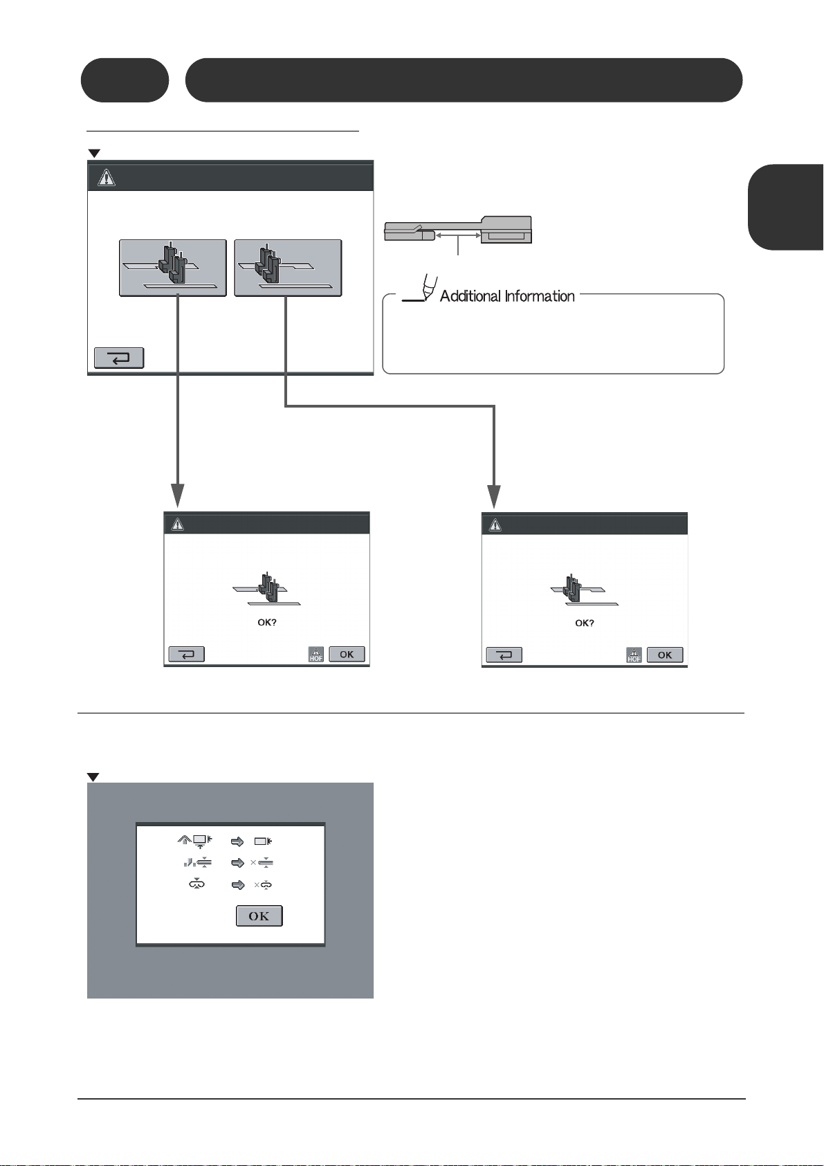
There is no instruction screen for the
guide bar attachment. Attach the guide
bars if necessary.
11119
10304C1
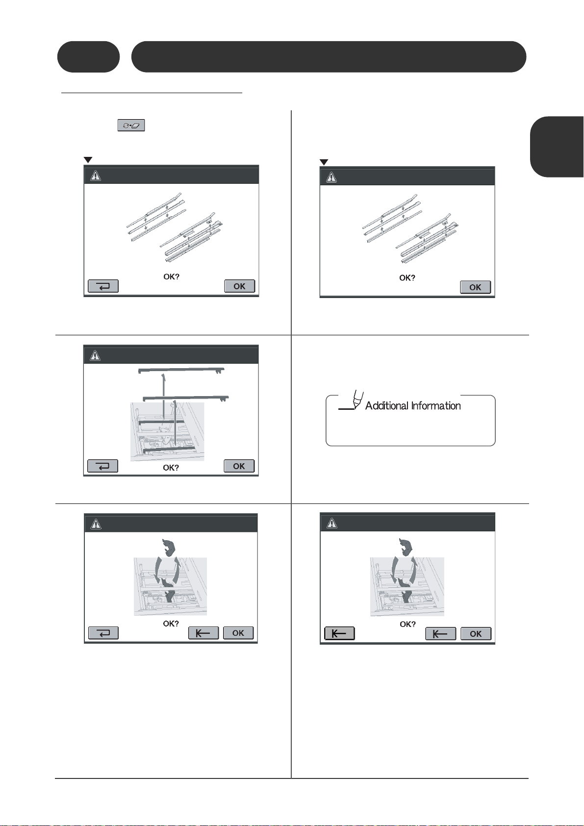
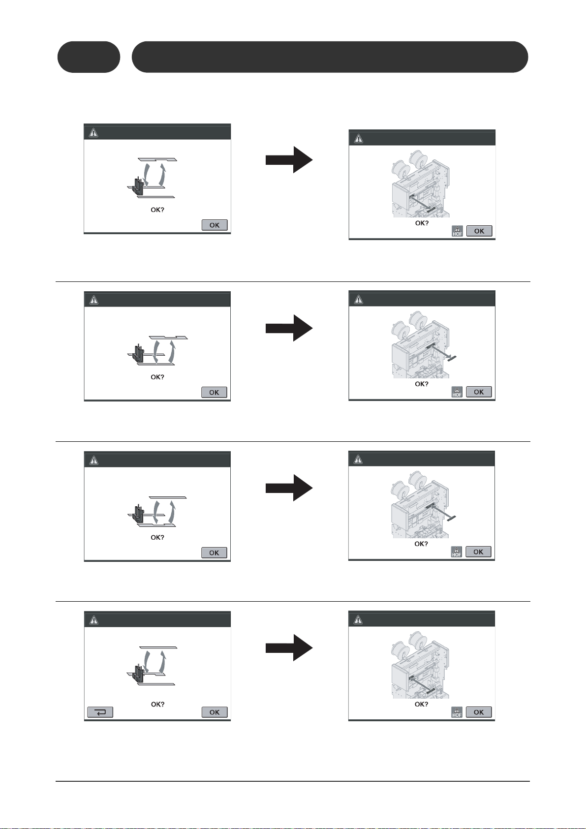
1-3-4 Setting-Instruction Screen
1-3-4
Setting-Instruction Screen
If you press , the following instruction
screens appear:
11119
10304A1
Remove the upper and lower parts for the top and
bottom guides.
The following screens are displayed after the
changeover.
1
Machine Description
Attach the upper and lower parts for the top and
bottom guides.
Screen Descriptions /
Remove the guide bars.
Replace the large saddle stitch stopper with the
small one.
11119
10304F1
Replace the small saddle stitch stopper with the
large one.
15
Page 24
1-3 Screen Descriptions
11119
10304J1
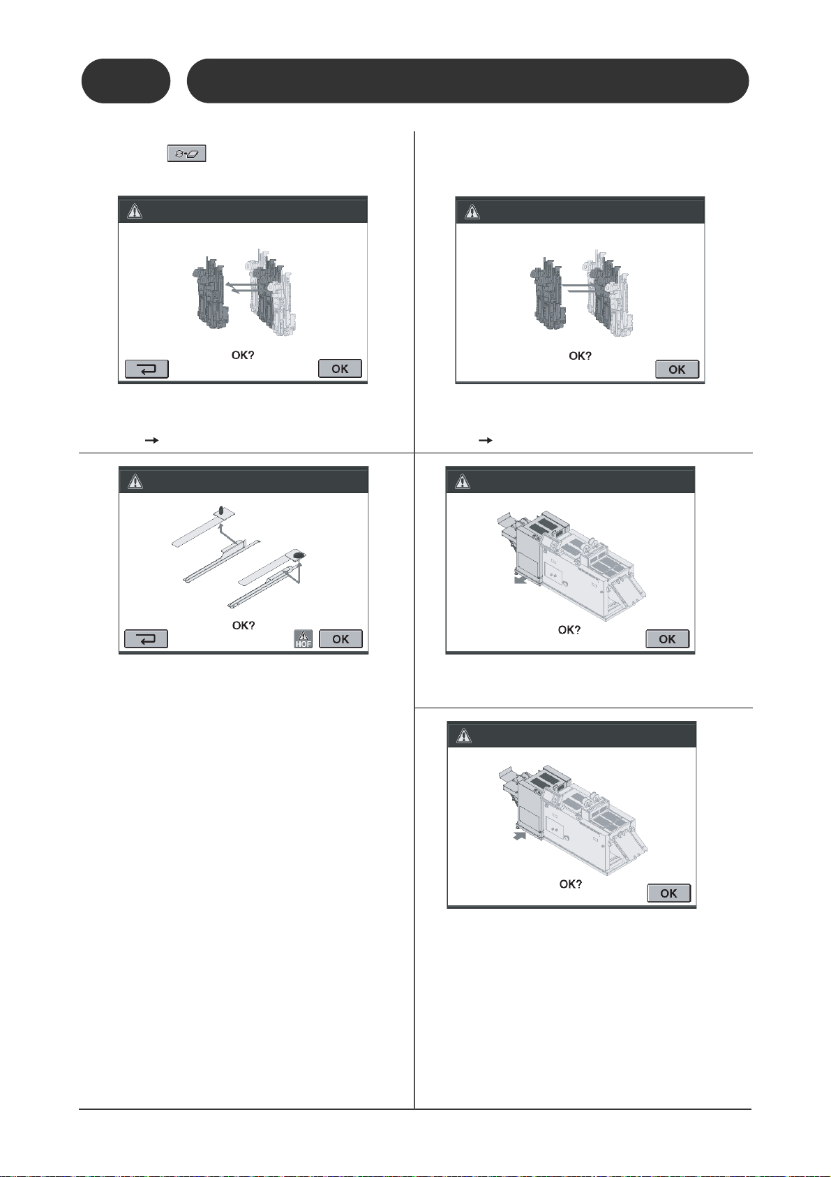
1-3-4
Setting-Instruction Screen
If you press , the following instruction
screens appear:
11119
10304D1
Remove two stitcher head assemblies, including
the mounting block and the clincher inside.
(Four stitch Two stitch)
The following screens below are displayed after
the changeover.
11119
10304G1
Attach two stitcher head assemblies, including the
mounting block and the clincher inside.
(Two stitch Four stitch)
Remove the sheet hold-down plates in the fold
section.
11119
10304H1
Move the fore-edge trim section to the front (for
small sheets).
11119
10304I1
Move the fore-edge trim section back (for normal
or large sheets).
16
Page 25
1-3 Screen Descriptions
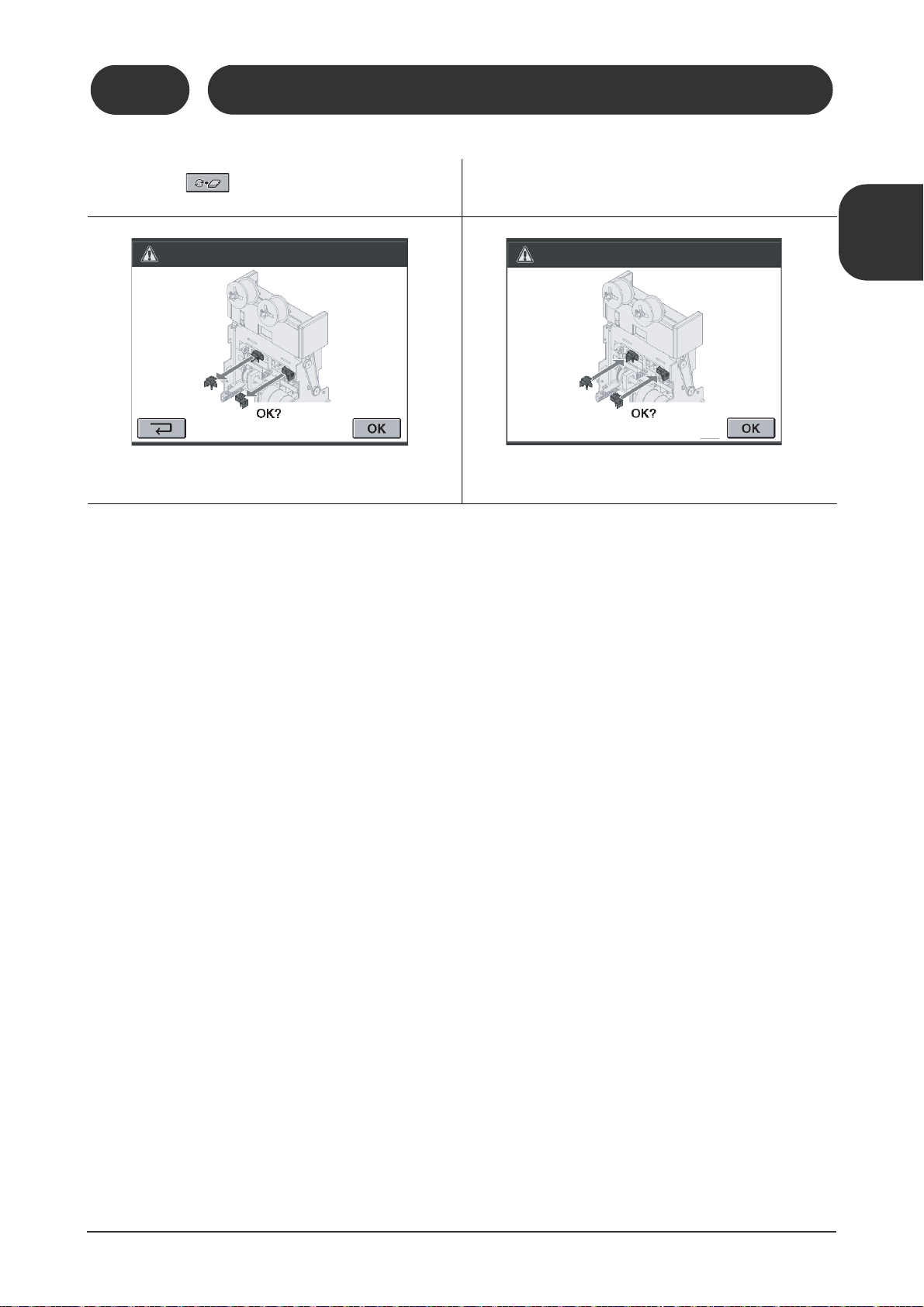
1-3-4
Setting-Instruction Screen
If you press , the following instruction
screens appear:
11119
10304K1
The following screens below are displayed after
the changeover.
Remove the stitch detection sensor. Install the stitch detection sensor.
11119
10304L1
1
Machine Description
Screen Descriptions /
17
Page 26
11119
10305F1
11119
10305L1
11119
10305M1
1-3-4
1-3 Screen Descriptions
Setting-Instruction Screen
If corner stitching has just been selected, or if you are stopping corner stitching and using another
binding pattern, the following instruction screens are displayed. (Corner stitching is an option.)
11119
10305G1
Replace the rear top and bottom guides
with the corner stitch guides.
11119
10305H1
Replace the front top and bottom guide with
the corner stitch guides.
Remove the front stitcher head drive block.
11119
10305I1
Remove the rear stitcher head drive block.
11119
10305J1
Replace the front corner stitch guide with
the top and bottom guides.
Replace the rear corner stitch guide to the
top and bottom guide.
18
11119
10305K1
Attach the rear stitcher head drive block.
Attach the front stitcher head drive block.
Page 27
1-3 Screen Descriptions
11119
10305N1
21102
10305Q1
Stitcher Head Position Confirmation Screen
If the stitch heads are positioned in
the hollow area of the corner stitch
guide:
Setting Confirmation Screen
Automatically deactivated functions due to the selected sheet
size are displayed here.
Hollow Area Under Corner Stitch Guide
If the stitch heads are positioned
outside the hollow area of the corner stitch guide:
This screen confirms the stitcher head position. Check the position of
the stitcher head in relation to the corner stitch guide.
If the stitcher head is positioned in the hollow area of the
corner stitch guide, the stitcher head can interfere with the
guide during changeover. This screen appears to prevent
the stitcher head from hitting with corner stitch guide.
1-3-5 Setting-Confirmation Screen
1-3-5
Setting-Confirmation Screen
11119
10305R1
1
Machine Description
Screen Descriptions /
11119
10305O1
11119
10305P1
19
Page 28
1-3 Screen Descriptions
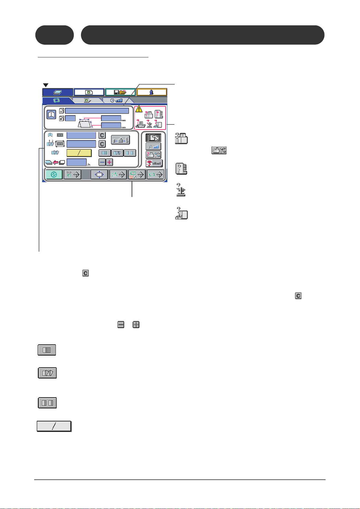
Operation Screen
Job Information
The job name and the job number are displayed after the job
is saved.
Upstream/Downstream Device Information
= The SPF-200A/200L or FC-200A/200L has a problem.
Press to learn about the problem.
= The collator has a problem.
= A downstream device has a problem.
= Trim Full
If the binding operation continues for one more minute,
feeding stops.
Total Count
- The total binding count is displayed here. The total count does not clear even when the power is turned Off. To clear the
total count, press .
Batch Count
- When delivered booklets are offset, the number of batch is displayed here. To clear the batch count, press .
Production Speed (book per hour.)
- Maximum production speed differs depending on the binding type, sheet size, and the status settings. When the production speed is changed using the or , the feeding speed from the upstream device will adjust automatically.
Delivery Conveyor Offset settings
= The booklets are delivered straight without offsetting.
= The last booklet is offset when the count reaches a preset number.
(This icon is available only if the optional PK-30 Kicker is connected.)
= The booklets are offset by changing the speed of the delivery conveyor.
=The current number of booklets / The preset number of booklets per batch (Available range: 1 to 99)
See Next Page
1-3-6 Binding-Operation Screen
1-3-6
Binding-Operation Screen
21102
10306A1
20
Page 29
1-3 Screen Descriptions
21102
10305D1
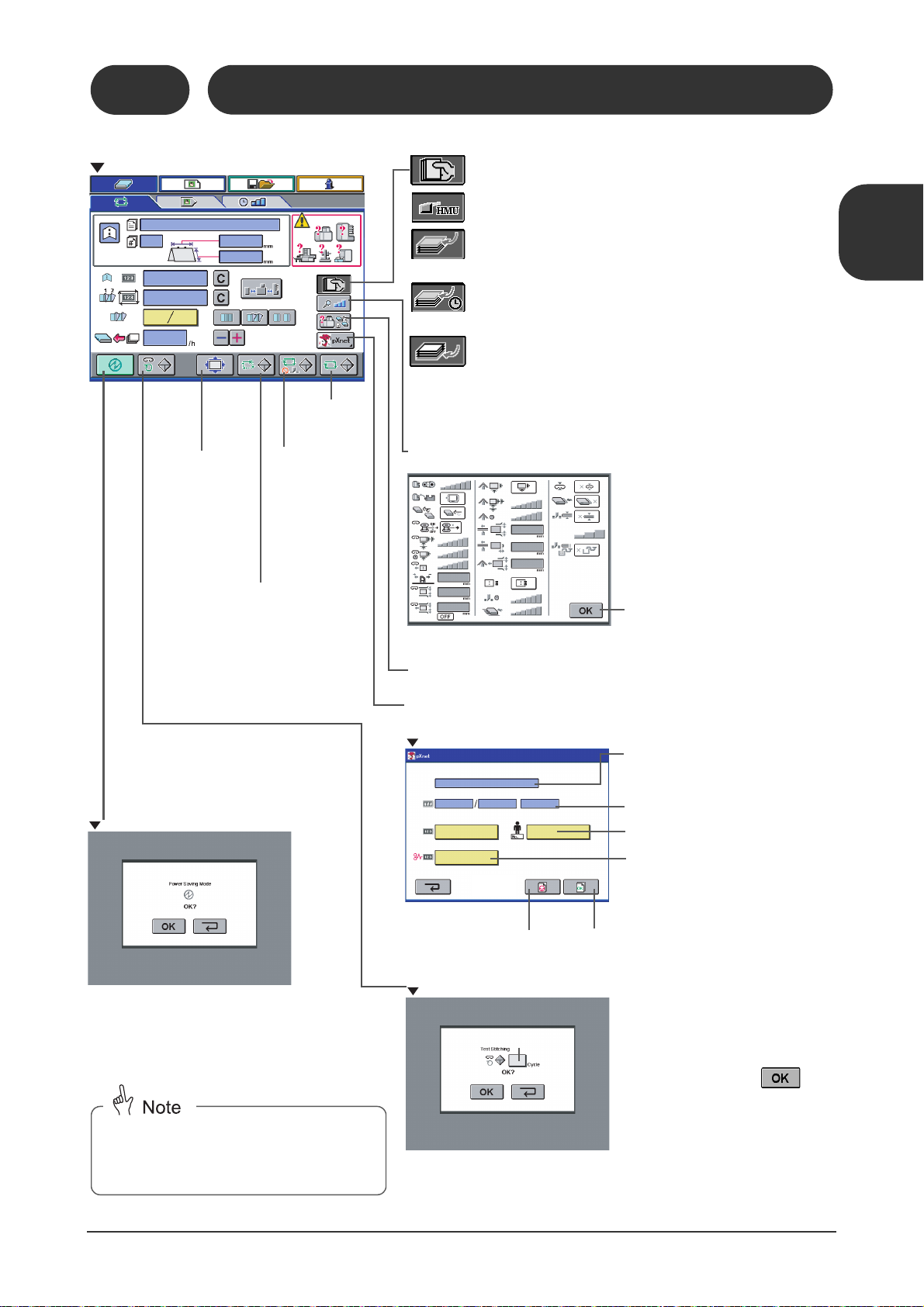
Operation Screen
= Only manual feeding
= Using the HMU (Hand Marry Unit on the collator)
= Feeding starts from the collator after sheets are loaded
into the manual feed section.
= Feeding the sheets manually to match the feed
from the collator.
= When feeding the sheet manually under the sheets fed
from the collator.
This button is available only if the SPF-200A/200L
is operated using the pXnet system.
Jog Button
Press once to jog
the sheets using
the guides. Press
again to deactivate
jogging.
This mode is used to reduce power consumption when the machine will not be
operated for a long time.
This button is used to do the
test binding step by step.
When this button is pressed,
the Binding-Fine Adjust screen
is displayed and one sheet is
transported to the jog section.
Status Indication Screen
After you press the button for the
setting to be changed, the BindingStatus Setting screen is displayed.
Return to the Operation screen.
pXnet Screen
The total binding count and the numbers of the remaining sets at starting
or restarting are displayed.
Enter the number if you are changing
the operator.
Press this button to pause the
current job and start another job.
Press this button when the job is
complete.
Place a sheet which is the same size
as the current setting under the
stitcher head, and press
.
The sheet will be stitched the preset
number of times.
Available Range:3 to 30
Power Saving Mode
Confirmation Screen
The touch panel turns off and the machine enters
the power saving mode. When you touch the
screen, the Setting screen is displayed, and the
machine returns from the power saving mode. Do
a changeover.
When the machine returns from the power
saving mode, changeover is required. Save
the job before entering the power saving
mode.
Error screen is displayed.
One booklet
is produced
as a test.
Stitching Test Screen
One booklet is
produced without trimming as
a test.
Enter the number of faulty sets.
The job name is displayed.
21102
10305A1
Binding-Operation Screen
21102
10305B1
1-3-6
1
Machine Description
Screen Descriptions /
21102
10305C1
21102
10305E1
21
Page 30
1-3 Screen Descriptions
11119
10307E1
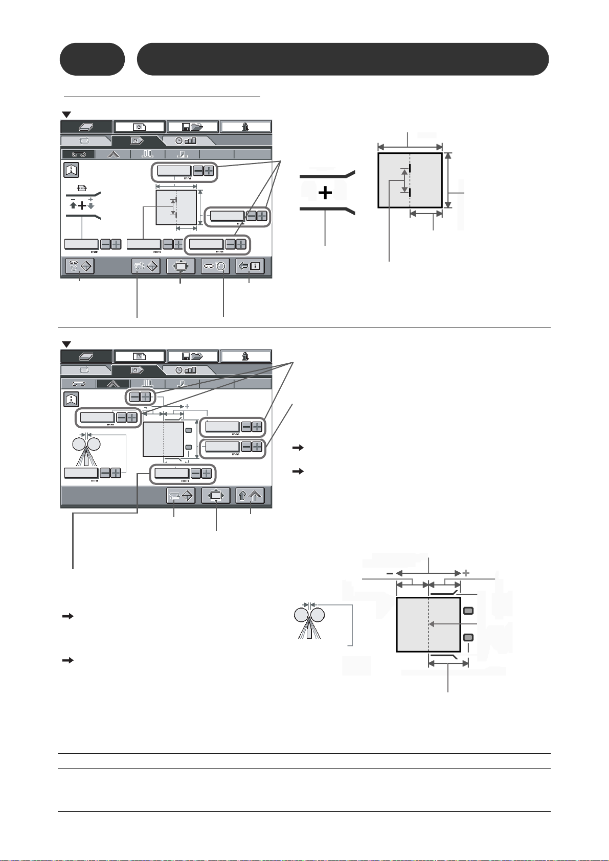
Fine Adjust-Stitch Section Screen
The sheets are
stitched the set
number of times.
The sheets are fed to the jog section.
Press once to jog the
sheets.
The sheets are transported
to the fold section.
These areas can be
changed when sheets
are being jogged.
Body fore/back position:
(-10.0 to +10.0mm)
(-0.400 to 0.400")
Press to stitch once.
Distance between jog plate and the stopper:
(-10.0 to +10.0mm)(-0.400 to 0.400")
Top and bottom guide
width:
(-10.0 to +10.0mm)
(-0.400” to 0.400")
Stitch position:
(-10.0 to +10.0mm)(-0.400 to 0.400"
Stitch distance:
(-10.0 to +10.0mm)(-0.400 to 0.400")
Distance between fold
knife and the stopper:
(-10.0 to +10.0mm)
(-0.400 to 0.400")
The parts move together so
that the distance between the
stopper and the jog pusher
does not change.
Distance
between fold
roller and the
jog pusher:
(-10.0 to
+10.0mm)
(-0.400 to
0.400")
Distance between fold knife and the forward
roller: (-10.0 to +10.0mm)(-0.400 to 0.400")
Maximum Fine Adjust Value =
4.0mm (0.15")-(booklet thickness)
Booklet Thickness
Fold Position
(Knife)
Fine Adjust-Fold Section Screen
These areas can be
changed when sheets
are being jogged.
The sheets are fed to
the fold section.
Press once to jog
the sheets.
Transport the sheets to
the next process.
The Fine Adjust- Punch Section Screen is described in the user's manual of the HP-200A hole punch unit.
The status setting of "fold section jog direction" has influence on
this area.
If the sheets are jogged by the jog pusher and the top and bottom
guides:
This area can be changed only when sheets are being jogged.
If the sheets are jogged only by the jog pusher:
This area always cannot be changed.
The status setting of "forward roller movement" has
influence on this area.
If the sheets are jogged while being pushed by the
forward rollers:
This area can be changed whether the sheets
are being jogged or not.
If the forward rollers move away from the sheets
when the sheets are being jogged:
This area can be changed only when the sheets
are not being jogged.
1-3-7 Binding-Fine Adjust Screen
21102
10307A1
11119
10307D1
1-3-7
Binding-Fine Adjust Screen
22
21102
10307B1
11119
10307F1
11119
10307G1
Page 31

1-3 Screen Descriptions
21102
10307C1
11119
10307I1
Transport Belt Height
Maximum fine adjust value: 7.0mm (0.275")(booklet thickness)
Finishing fore-edge dimension: (-10.0 to +10.0)
(-0.400” to 0.400”)
The default setting for the trim width is 3mm
(0.125").
Feed the sheets to the
fore-edge trim section.
Lower the
transport belts.
Trim once.
Press this button to
deliver the sheets.
Fine Adjust-Fore-edge Trim Section Screen
This area can be
changed when the
transport belts are
raised.
1-3-7
Binding-Fine Adjust Screen
11119
10307H1
1
Machine Description
Screen Descriptions /
23
Page 32

1-3 Screen Descriptions
This button is used to match (decrease)
the speed of the trim section with the
stitch section and prevent a booklet from
being pulled while delivery when using
single sheet or performing the job with
folding only.
21102
10308A1
Collator/Faulty Set Detect/Manual
Feed/Stitch Screen
- Normally use .
- If there is just a small amount of wire left, the sensor may keep deactivating
even though the wire is being fed correctly. If this happens, select .
1-3-8 Binding-Status Setting Screen
Items marked like this are default settings.
Transport Speed
This indicates the operating speed of the belt or roller. It
can be adjusted in six steps.
VAC Support Guide
(Used for sheets with a width smaller than 148 mm (5.83”).)
= Guide is not used.
= Guide is used. This can be selected when sheet
width is 230 mm (9.05”) or smaller.
Faulty Set Ejection
= Faulty Set Ejection Off
1-3-8
Binding-Status Setting Screen
= Faulty Set Ejection On (When an error
occurs in the upstream device, booklets are
delivered to the mis-feed tray without trim.)
Wire Feeding Detection
This function is used to watch that the wire is fed correctly.
= Off
= An error is detected if the sensor is activated for a set time.
= An error is detected if the sensor is active or not active for
longer than the specified time.
Manual Feed Setting
= No manual feeding
= Only manual feeding
= Using the HMU (Hand Marry Unit on the collator). This function cannot be selected from the screen.It must
be selected by using the switch on the HMU.
= Feeding starts from the collator after sheets are loaded in the manual feed section. (Production speed:
Slow)
= Use when feeding the sheet manually to match the feeding from the collator. (Production speed: Fast)
= Use when feeding the sheet manually under the sheets fed from the collator.
24
Page 33

1-3 Screen Descriptions
21102
10308H1
Collator/Faulty Set Detect/Manual
Feed/Stitch Screen
Items marked like this are default settings.
1-3-8
Binding-Status Setting Screen
Stitch Section Jogging Frequency
This indicates the number of jogs done before
stitching. Press if the sheets are not squared up.
(This will slow down the production speed.)
Stitch Delay Time
This indicates the delay from the moment the
sheets are transported from the jog section until the
sheets are stitched.
1
Transport Pusher Speed
Slow the speed of the transport pusher if the booklets
bend between the jog section and the fold section.
Transport Pusher Waiting Position
- The adjustable range is from -50 to +40mm (-1.97"
to +1.58".)
- If the transport pusher for paper inserter does not
catch the sheet, adjust the waiting position using
.
Stitch Section Top and Bottom Guide
Stroke
- This sets the opening between the top and bottom
guides when the sheets enter.
- The default setting is 3.0 mm (0.120").
- This is adjustable within 1.0 to 6.0 mm (0.050" to
0.200").
Machine Description
Screen Descriptions /
Stitch Section Top and Bottom Guide Delivery Stroke
- This indicates the opening between the top and bottom guides while the sheets are being delivered from the jog section.
- The default setting is 0.5 mm (0.025").
- This is adjustable within 0.5 to 2.0 mm (0.025" to 0.080").
=The guides open for the guide delivery stroke when the sheets are delivered. This ensures stable delivery
although the highest production speed is not available.
=The guides open for the normal guide stroke when the sheets are delivered.The delivered sheets may not
move correctly.
25
Page 34

1-3 Screen Descriptions
Fold/Fore-edge Trim/Conveyor
Screen
Fold Section Top and Bottom Guide
Delivery Stroke
- This indicates the opening between the top and
bottom guides while the sheets are being delivered.
- The default setting is 1 mm (0.040").
- This is adjustable within 0.5 to 3.0mm (0.025" to
0.100").
Fold/Fore-edge Trim/Conveyor Screen
Items marked this way are default settings.
Fold Section Jog Direction
= The
sheets are jogged
top and bottom guides.
= The
sheets are jogged only by the jog pusher.
Using the default setting, the sheets are jogged only by the jog
pusher. If you are doing folding only, or using the paper insertion
function, you must jog using the top and bottom guides.
Fold Section Jogging Frequency
If you are only doing folding and the sheets are
not arranged correctly, press .
Fold Delay Time
delay from the moment the sheets are transported to the fold
section until the sheets are jogged and folded.
by the jog pusher and the
1-3-8
Binding-Status Setting Screen
Fold Section Top and Bottom Guide Stroke
- This indicates the opening between the top and bottom guides while
the sheets are being fed.
- The default setting is 3.0mm (0.120").
- This is adjustable within 1.0 to 6.0mm (0.050" to 0.200").
When Stitch Section Top and Bottom Guide Delivery Stroke is On
If you set this value smaller than the stitch section top and bottom guide
delivery stroke, its value is also reduced.
When Stitch Section Top and Bottom Guide Delivery Stroke is Off
If you set this value smaller than the stitch section top and bottom guide
stroke, its value is also reduced.
Fold Section Jog Pusher Stroke
- This indicates the opening width of the jog pusher while
the sheets are being fed.
- The default setting is 5.0 mm (0.260").
- This is adjustable within 2.0 to 10.0mm (0.075" to 0.400").
21102
10308C1
Forward Roller Movement
The movement of the forward rollers while the sheets are
being jogged can be selected.
= The sheets are jogged while being pushed
by the forward rollers.
= The forward rollers move away from the sheets
when the sheets are being jogged. When using
thin sheets, they may be bent by the forward
roller and the jog error may not be detected correctly. If this happens, use this button.
Delivery Conveyor Run Distance for Offset Function
- When you use the offset function, this indicates how long
the conveyor runs between the last booklet in one batch
and the first one in the next batch.
- If the first booklet in the one batch slips inside the last one in
the previous batch, press to increase the run distance.
26
21102
10308G1
11119
10308F1
Fore-edge Trim Delay Time
- This indicates the delay from the moment the sheets reach
the fore edge trim stopper until the sheets are trimmed.
- Press to increase the pause time.
Delivery Conveyor Run Distance
- This indicates how long the conveyor runs after a booklet
is delivered.
- Press to increase the run time.
Page 35

1-3 Screen Descriptions
21102
10308D1
Option Screen
Option Screen
Return to the initial setting.
Items marked this way are default settings.
Stitch Detection
This function detects if the stitching has been done correctly.
It can be selected only if the optional SDS-200 is connected.
1-3-8
Binding-Status Setting Screen
Paper Insertion
This selects whether the paper insertion function is used. It
can be selected only if the optional PN-200 Paper Inserter
is installed.
= Off
= On
= Function not used
= Function used
1
Machine Description
Screen Descriptions /
21102
10308i1
21102
10308E1
FC Booklet Thickness Detection
Faulty set is detected by measuring the booklet thickness
in the fore-edge trim section. These buttons are active only
if the optional TD-200 is connected.
= Off
= On
Sensitivity Low High
Chip Extractor
This sets whether the optional TB-200 Chip Extractor is
used. These buttons are active only if the TB-200 is connected.
= Not Used
= Used
27
Page 36

1-3 Screen Descriptions
Job No. Input
Enter the number of the job to be
displayed using the numeric keypad screen which appears when
this is pressed. (Job no.01 to
200)
Save Confirmation Screen
Keyboard Screen
Save
This saves the current machine
settings under the selected job number.
= This uses the stan-
dard typewriter
keyboard layout.
= The keys are laid
out in alphabetical
order.
Display Window Up to 19 letters can
be entered.
= The job is saved and the Memory-
Main screen is displayed.
= The Memory-Main screen is displayed
without saving the settings.
Detailed Information Screen
Delete Confirmation Screen
Load Confirmation Screen
1-3-9 Memory Screen
21102
10309A1
1-3-9
Memory Screen
The detailed information for the selected job is displayed.
21102
10309B1
Scroll Buttons
= Screen Scrolling (5 previous jobs)
= Scrolling (up)
= Scrolling (down)
BOOK
1
Book
21102
10309C1
=
Screen Scrolling (5 following jobs)
Delete
The selected job is deleted.
(* Once deleted, the job cannot be recalled.)
21102
10309F1
= The job is deleted and the Memory-
Main screen is displayed.
= The Memory-Main screen is displayed
without deleting the job.
Load
The selected job is loaded.
28
21102
10309D1
21102
10309E1
= The Setting-Finishing Size screen is
displayed. Do the changeover.
= The Memory-Main screen is displayed
without loading the job.
Page 37

1-3 Screen Descriptions
21102
10310A1
Information-Main Screen
Password Input Screen
Administrator Mode Screen
A Password is required to display this screen.
Enter the password
and then press
.
See [1-3-12]
This button is used by
the service person
only.
See next page.
This is the total binding count
since the machine was shipped.
This counter can be cleared
in the Administrator Mode.
Use the counter as a guide
for trim knife replacement.
This is the total trim count since
the machine was shipped.
21102
10310D1
System Error Code
The last eight errors are shown on the
page, and a total of 24 errors are
recorded.
This shows the system configuration and any optional
devices which are installed with the SPF-200A/200L.
These settings can be changed in the Administrator Mode.
1-3-10 Information-Main Screen
1-3-10
Information-Main Screen
11119
10310F1
1
Machine Description
= Counter
= Error History = System Configuration /Option
21102
10310B1
= Software Version/Serial Number
21102
10310C1
Screen Descriptions /
21102
10310E1
29
Page 38

1-3 Screen Descriptions
Each section of the machine
can be operated separately
using these screens.
2110110311H1
Stepper Motor Lock Release
If the is displayed you can
move each guide and stopper by hand.
The input condition of each sensor signal can be monitored using
these screens.
= Sensor is inactive (Off).
= Sensor is active (on).
2110210311E1
2110210311D1
Stepper Motor Lock Release
If the is displayed you can move each guide and stopper
by hand.
Information-Monitor/Single Operation Screen
1-3-11 Information-Monitor/Single Operation Screen
= Single Operation
21102
10311A1
1-3-11
= Monitor
2110210311F1
2110210311G1
30
2110210311B1
2110210311C1
Page 39

1-3 Screen Descriptions
21102
10312A1
21102
10312D1
21102
10312E1
21102
10312F1
Administrator Mode Screen
= Page 32
= Page 32
= Next page
= Next page
Power Saving Mode
When is selected, enter
the time until the machine goes
over to a power saving mode.
(The possible delay range is 1
to 120 min.) If the machine is
not operated within the delay
period, it automatically switches
to the power saving mode.
Press to clear the counter.
Administrator-Password Screen
Press after the password is entered.
Trim Count
The same trim count as on the Information-Counter screen is displayed here.
Information-Counter
Screen
Wire Feeding
Detection
= An error is triggered
if the sensor has
been activated even
though the stitching
has been done for the
correct number of
times.
= An error is triggered if
the sensor is not activated even though
the stitching has been
done for the correct
number of times.
ON
OFF
The top and bottom guides open and release.
The guides return to the set positions.
Stitch Section Top and Bottom
Guide Adjustment
This screen is used to ensure that the top
and bottom guides are parallel.
1-3-12 Information-Administrator Screen
1-3-12
Information-Administrator Screen
11119
10312B1
21102
10312C1
1
Machine Description
Screen Descriptions /
31
Page 40

1-3 Screen Descriptions
21102
10312G1
21102
10312I1
Enter the correction or offset value here. To
increase the correction, use a larger number
The values entered on the current fine
adjustment screen are displayed here.
This corrects the home position value so
that the fine adjustment value becomes
zero.
This corrects the home position values so
that the all fine adjustment values
become zero.
= Home Position Calibration
= Input Signal ON/Off
If one of the motors or sensors stops working, the binding operation can
be continued by turning off the broken motor or sensor.
If you want to turn off one of these motors, contact a service technician
for detailed instructions.
= The selected motor or
sensor is included in
the control circuit.
= The selected motor or
sensor is taken out of
the control circuit and
will not operate.
The binding quality may not be reliable
if you turn off one of the motors or sensors.
If you find yourself making the same fine adjustment every time, the
home position can be calibrated so that no adjustment is required.
This is available only when saddle stitch is selected.
Information-Administrator Screen
21102
10312H1
1-3-12
21102
10312M1
21102
10312J1
32
Page 41

1-3 Screen Descriptions
21102
10312N1
21102
10312S1
=
System Configuration
Use this to select the upstream/downstream devices connected to the SPF200A/200L.
= Option
Use this to selected the optional devices installed with the SPF-200A/200L.
SSK-200A
/SSK-200L
SDS-200
PN-200
FST-200
PK-30
TD-200
TB-200
=
=
=
=
=
=
=
Horizontal Transport
Mis-stitch Detector
Paper Inserter
Four Stitching Kit
Preset Kicker
FC Booklet Thickness Detector
Chip Extractor
1-3-12
Information-Administrator Screen
21102
10312T1
1
Machine Description
21102
10312R1
Screen Descriptions /
33
Page 42

1-3 Screen Descriptions
= A jog error has occurred in the fold section.
= The feed interval between the booklets is too short,
and the booklets are not trimmed correctly.
= The transport belt speed in the FC-200A/200L is
slower than the belt speed in the upstream device.
= The communication network has a problem.
= An error has occurred in a device downstream of
the FC-200A/200L.
= The faulty Set ejecting tray is full.
= A wire feeding error has occurred in the stitch sec-
tion.
= A faulty set cannot be ejected to the faulty set eject-
ing tray.
= Jog section top and bottom guide or transport
pusher overload.
= The trim chute is full.
= The stitcher head is not at the correct position.
Option
= The front wire is not stitched.
= The rear wire is not stitched.
= A booklet thickness error has been detected in the
fore-edge trimmer.
Go to the
Binding-Operation screen
This icon is displayed
if a system error
occurs.
An error code is displayed here if an
error occurs during the binding operation and the machine stops.
If a faulty set is ejected to the
faulty set ejection tray, an error
icon is displayed here.
Error Icon
= A cover is open.
= An Emergency Stop button is pressed.
= A sheet jam has occurred.
= An upstream device has a problem.
= No sheets are arrived in the machine within 10
seconds after the binding operation started.
= The sheets needed for manual feeding are not in
position.
.
= There is a communication error with an upstream
device.
1-3-13 Error Screen
This section explains the function of the error screen and how to interpret the error icons.
See Section 5-1-1 for instructions on recovery after an error.
11119
10313A1
1-3-13
Error Screen
34
Page 43

s
Initial Screen
Setting-Binding
Pattern Screen
21102
20101E1
OK
2
21102
20101F1
3
Setting-Binding Pattern Screen
Setting-Sheet Size Screen
Setting-Finishing Size Screen
Instruction-Removal Screen
Binding-Operation Screen
Error Screen
2 Checks before Operating
This chapter explains the safety checks you must make before beginning the binding
operation.
2-1 Checking the Emergency Stop Function
This machine has many safety functions designed to protect customers from possible risk during operation. Before operating the machine, check that all of the safety functions are working normally.
The Emergency Stop circuit is activated after
the power switch is turned On and all sections of the machine have returned to their
home positions.
1
Turn on the power switch.
- Turn the handle to the right to turn on the switch.
The Set-up screen and then the Setting-Binding
Pattern screen are displayed on the touch panel.
- If the HOF-400/HOF-30/HOF-20 is connected,
turn on the power switch for that also.
- If the icon
is displayed on the Initial
screen, it indicates that there is a problem with
the system configuration settings.
Press
to reset the system configuration.
- If the icon
is displayed on the Initial screen,
refer to Section 5-1-1 to correct the problem.
2
Do the changeover.
1.Press
.
11119
20101A1
11119
20101B1
2
Checks before Operating
ONONON
2110220101C1
The Setting-Sheet Size screen is displayed.
2.
Press .
The Setting-Finishing Size screen is displayed.
Press .
3.
The Instruction-Removal screen is displayed.
4. Press .
The Binding-Operation screen is displayed
when the changeover is complete.
Press .
5.
The Error screen is displayed.
21102
20101D1
1
Checking the Emergency Stop Function /
21102
20101G1
4
5
21102
20101H1
1111920101N1
35
Page 44

2-1 Checking the Emergency Stop Function
If an error icon is not displayed
4
3
2
1
1234
5
6
If an error icon is not displayed
6
5
Press
Release
3
Check the safety interlocks on the
safety covers.
- Check that the correct icon is displayed on
the screen when you open each of the following covers:
1. Infeed Section Cover
2. Stitch Section Cover
3. Fold Section Cover
4. Fore-edge Section Cover
- Each error icon will disappear when the
cover is closed.
- There is a problem with the safety circuit.
Stop using the machine and make a service
call.
4
Check the safety functions of the
Emergency Stop buttons.
- Press each Emergency Stop button.
The machine has two Emergency Stop buttons.
5. SPF Main Unit Emergency Stop Button
6. Fore-edge Trim Section Emergency
Stop Button
- Check that the correct icon is displayed on
the screen.
- Each error icon is cleared by turning the
Emergency Stop button clockwise and pulling up.
11119
20101A1
4
3
2
6
5
1
11119
20101J1
11119
20101K1
- There is a problem with the safety circuit.
Stop using the machine and make a service
call.
36
11119
20101L1
11119
20101M1
Page 45

ds
21102
30101C1
11119
30101E1
3 Operating Procedures
This chapter describes the procedure for doing a regular bookbinding job.
3-1 Overview of Operating Procedures
This section provides an outline of the procedure for the bookbinding job.
Refer to Section 3-2 for details.
Turn On Power
1
Chapter 2, “Check Before
Operating.”
Set Up Job - Setting
2
Screen
Select the binding type.
Enter the sheet size.
Enter the finishing size.
Do the Changeover
3
Refer to
page 35
Refer to
page 39
Refer to
page 44
21102
30101A1
OK
21102
30101B1
3
Operating Procedures
Press .
Remove the required parts before doing
the changeover.
Do the changeover.
Attach the required parts after doing the
changeover.
Confirm the settings after doing the
changeover.
21102
30101D1
11119
30101F1
Overview of Operating Procedures /
37
Page 46

3-1 Overview of Operating Procedures
21102
30101N1
11119
30101O1
Test Binding
4
Prepare the upstream device.
Produce one booklet, or do a test binding
and check all of the settings.
Do some test stitching, if necessary.
Refer to
page 53
123
1
2
3
4
5
6
7
8
9
10
1
2
3
4
5
6
7
8
9
10
10
1
2
3
4
5
6
7
8
9
21102
30101J1
1
2
21102
30101H1
11119
30101G1
21102
30101L1
Confirming the Status
5
Settings
VAC support guide Use/Not Used
Faulty Set Ejecting Function On/Off
Wire Feeding Detection On/Off
Manual Feeding On/Off
Optional Device Settings
Start Binding
6
Set the offset function.
Press the Start button.
Press the Stop button to complete the
operation.
Refer to
page 60
Refer to
page 62
21102
30101I1
21102
30101M1
21102
30101K1
38
Page 47

3-2 Setting Up a Job Using the Setting Screen
Rear Corner Stitch
(Option)
Fold Only
Side Stitch and Fold
Side Stitch (Option)
Front Corner Stitch (Option)
Saddle Stitch
Pass Through
(Option)
The following sections include detailed
instructions for each part of the machine.
Select the binding pattern.
1
- Select the icon which indicates the required
binding pattern.
The Sheet Size screen is displayed.
21102
30201A1
3
Operating Procedures
Setting Up a Job Using the Setting Screen /
39
Page 48

3-2 Setting Up a Job Using the Setting Screen
Top/Side Stitch
Sheet Size A=Length B=Width
Max. mm (inch)
432.0
(17.000")
356.0
(14.000")
Min. mm (inch)
138.0
(5.435")
180.0
(7.090")
Corner Stitch
Sheet Size A=Length B=Width
Max. mm (inch)
364.0
(14.330")
326.0
(12.820")
Min. mm (inch)
210.0
(8.270")
210.0
(8.270")
Top Stitch and Fold
Sheet Size A=Length B=Width
Max. mm (inch)
432.0
(17.000")
356.0
(14.000")
Min. mm (inch)
180.0
(7.090")
180.0
(7.090")
Saddle Stitch/Fold Only/Pass Through
Sheet Size A=Length B=Width
Max. mm (inch)
(For the SPF-200A)
508.0
(20.000")
356.0
(14.000")
Max. mm (inch)
(For the SPF-200L)
610.0
(24.015")
356.0
(14.000")
Min. mm (inch)
180.0
(7.090")
120.0
(4.725")
OK
21102
30201B1
AA
BB
CC
Sheet Size Screen
Select one of these
if you are using a
standard size
sheet.
A
B
E
D
Sheet Size Screen
HOF Error
Icon
No changeover is
done and the Binding screen is displayed.
All sections return to their home positions before beginning the changeover.
The machine starts the
changeover.
The range of sheet sizes available can be limited if the
sheets are fed from the machines listed below.
- VAC-100/60H/1000/600H
Max. W 350.0 X L 500.0 mm (13.775” X 19.685”)
Min. W 120.0 X L 148.0 mm (4.725” X 5.830”)
- HOF-20/30
Max. W 350.0 X L 500.0 mm (13.775” X 19.685”)
Min. W 200.0 X L 275.0 mm (7.875” X 10.830”)
- ST-40 (Only when the ST-40 is used as bypass to the stitcher)
Max. W 350.0 X L 500.0 mm (13.775” X 19.685”)
Min. W 182.0 X L 128.0 mm (7.166” X 5.040”)
- BC-20
Max. W 350.0 X L 500.0 mm (13.775” X 19.685”)
Min. W 128.0 X L 148.0 mm (5.040” X 5.827”)
* When the LG-1000 is installed on the VAC-100 or the
VAC-1000, the maximum available length for the
SPF-200L is 610 mm (24.015”).
* When the ST-40 is connected with the SPF-200L,
even a long sheet (up to 610 mm or 24.015") can be
rejected to the ST-40, if the stopper plate for the ST40 is removed.
Enter each dimension.
2
- Enter in steps of 0.1 mm (0.005").
A: Sheet Length
B: Sheet Width
When doing saddle stitching -
When doing side stitching -
A
B
21102
30201C1
D
E
C: Stitch Position
- Half of the sheet length is automatically
displayed.
D: Stitch Distance
E: Booklet Thickness
- Measure the thickness using a caliper
(accessory) and enter the value within 0.1
to 4.0 mm (0.005" to 0.155").
40
Page 49

3-2 Setting Up a Job Using the Setting Screen
B
C
A
B
E
D
Sheet Size-Other Binding Pattern Screen
Sheet Size-Saddle Stitch Screen
(This example shows the screen
for side stitching.)
When doing saddle stitching -
3
-Press .
The Finishing Size screen is displayed.
When doing binding patterns
except saddle stitching -
-Press .
- If the HOF error icon is displayed, there is a
problem with the HOF-20/30. Clear the error
on the HOF-20/30 before trying to do the
changeover.
The Setting-Instruction screen is displayed.
Go to Section 3-3.
AAA
B
C
OK
A
B
D
E
21102
30201G1
3
Operating Procedures
Setting Up a Job Using the Setting Screen /
41
Page 50

3-2 Setting Up a Job Using the Setting Screen
Finishing size Top and Bottom
Max.
(with foreedge trim)
(For the
SPF-200A)
254.0mm or
10.000”
(250.0mm or
9.840”)
356.0mm or
14.000”
Max.
(For the
SPF-200L)
305.0 mm or
12.00”
356.0mm or
14.000”
Min.
85.0mm or
3.350”
120.0mm or
4.725”
Top and
Bottom
Finishing size
On a machine set to measure in inches, you
must set the stitch distance carefully so the
stitches do not hit the fold knife or booklet stopper. For details, see Section 1-3-3.
21102
30201E1
AA
BB
CC
Finishing Size Screen
Select one of these
if you are using a
standard sheet
size.
Stitch Type
Select a stitch type from the 5
choices. (When using small
size sheets, the four stitch may
not be selected.)
Flat
Loop
Press this button to do
a fore-edge trim.
HOF Error
Icon
= No changeover is done and the Binding screen is
displayed.
= Each section returns to the home position before
starting the changeover.
= The machine starts the changeover without sending
the parts to their home positions.
The actual positions of the guides and stoppers may be
different from the set positions. If there is a problem with
the binding quality, send all of the parts to the home positions before doing the changeover.
= Caution Icon for
Fold Skewing
= Caution Icon for
Crooked Trim
Enter all of the dimensions.
4
- Enter the finishing size for saddle stitch or
fold only.
- Enter in steps of 0.1 mm (0.005").
A: Finishing Size
11119
30201D1
B: Stitch Distance
- We recommend you to adjust the stitch
distance within the ranges shown below:
If the top and bottom distance is 185
mm (7.285") or more
- 79.0 to 92.0 mm
- 138.0 to 151.0 mm
- 3.860” to 5.905"
If the top and bottom distance is shorter
than 185 mm (7.285")
- 79.0 to 80.9 mm
11119
30201F1
- If the stitch distance is adjusted outside
of this range, the folding or trimming
42
may be incorrect.
C: Booklet Thickness
Measure value using a caliper (accessory)
and enter the value within 0.1 to 4.0 mm
(0.004" to 0.15").
Page 51

3-2 Setting Up a Job Using the Setting Screen
Press .
5
The Setting-Instruction screen is displayed.
- If the HOF error icon is displayed, there is a
problem with the HOF-20/30. Clear the
error on the HOF-20/30 before doing the
changeover.
- Go to the next page.
3
Operating Procedures
Setting Up a Job Using the Setting Screen /
43
Page 52

3-3 Doing a Changeover
Guide Bar
Remove the
guide bars in the
jog section.
Remove the
upper and lower
section of the top
and bottom
guides.
1. Loosen
Upper Part of
the Guide
Remove
Remove
3.
2.
1. Loosen
Lower Part
of the Guide
This section explains how to remove or attach
the guides and stoppers before and after the
changeover by referring to the Instruction
screen.
3-3-1 Removing Parts Before the
Changeover
After removing the specified parts, press .
11119
30301A1
3-3-1 Removing Parts Before
the Changeover
11119
30301C1
11119
30301D1
11119
30301B1
11119
30301E1
44
Page 53

3-3 Doing a Changeover
- Replace the large saddle
stitch stopper to the small
one.
- Loosen the locking screws
to remove the stopper.
Lock by pressing the
stopper down.
If the stopper is located in a place where it is hard
to reach the locking screws, press .
The stopper will move to a better location.
11119
30301G1
Locking Screws
- Remove the sheet holddown plates in the fold
section.
- Once you remove the locking knob, the plate can be
removed.
11119
30301H1
Locking knob
Remove two stitcher head
assemblies, along with the
mounting blocks and clinchers.
Be sure to remove the mounting block and
the clincher, not just the stitcher head.
CAUTION
11119
30301F1
3-3-1 Removing Parts Before
3-3-1 Removing Parts Before
the Changeover
the Changeover
3
11119
30301J1
11119
30301K1
- Refer to Section 8-3 for removal instructions.
11119
30301I1
Operating Procedures
Doing a Changeover /
45
Page 54

3-3 Doing a Changeover
If you press , the following instruction
screens appear:
11119
10304K1
Remove the stitch detection sensor.
Refer to Section 8-4.
3-3-1 Removing Parts Before
the Changeover
46
Page 55

11119
30301L1
11119
30301M1
Rear Corner Stitch Guide
Top and
Bottom
Guide
Positioning
Pin
Locking Screws
Fit here
Fit here
Top and bottom guide
mounting screws
Top and bottom guide mounting screws
11119
30301S1
11119
30301P1
11119
30301O1
3-3-1 Removing Parts Before
3-3 Doing a Changeover
- When you stop doing corner stitching and go to another binding pattern, or
- When you select corner stitching for the first time,
The stitch section moves to the left end, the top and bottom guides open, then the machine stops
before doing the changeover. (The top and bottom guide guides can be removed easily by hand.)
Replace the rear top
and bottom guides with
the corner stitch guide.
Replace the front top
and bottom guides with
the corner stitch guide.
Front corner stitching is optional.
11119
30301R1
Remove the front
stitcher head drive
block.
Remove the rear
stitcher head drive
block.
the Changeover
11119
30301T1
3
Replace the front corner stitching guide with
Attach the rear stitcher
head drive block.
the top and bottom
guides.
11119
30301N1
Replace the rear corner
stitching guide with the
Attach the front stitcher
head drive block.
11119
30301Q1
top and bottom guides.
Parallel Adjustment
Press and hold the top and bottom guides, and
tighten the mounting screws.
- Fit the left end of each guide over the bolt head.
11119
30301Z1
11119
30301U1
Operating Procedures
Doing a Changeover /
11119
30301V1
47
Page 56

3-3 Doing a Changeover
This screen is displayed in the situations listed
below because the machine does not know the
current positions of the stitcher heads.
- First changeover since the power was turned on.
- If an Emergency Stop button is pressed during a
changeover.
If the stitcher heads are positioned in the cutout of
the corner stitch guide, the stitcher heads will
interfere with the guide during the changeover.
This screen appears to prevent a case where the
stitcher heads hit the corner stitch guide.
Stitcher Head Position Confirmation Screen
Corner Stitch Guide
Cutout
- The screen shown to the right may be displayed
before you begin the changeover for corner stitching.
- This screen is used to confirm the stitcher head
positions.
- Select either icon.
A: The stitcher heads are positioned in the cutout
of the corner stitch guide.
B: The stitcher heads are positioned outside of the
cutout of the corner stitch guide.
11119
30301X1
11119
30301W1
3-3-1 Removing Parts Before
the Changeover
AB
- After making the right selection, press
.
11119
30301Y1
48
Page 57

3-3 Doing a Changeover
11119
30302H1
Attach the upper
and lower sections
of the top and bottom guides.
Upper Part of
the Guide
3. Tighten
Lower Part of
the Guide
1.
2.
Tighten
If you are using wide sheets, the sheets may sag
between the transport belt and the top and bottom
guides. If this happens, attach the guide bar.
Top and Bottom
Guide
Sag
Transport
Belt
Guide Bar
11119
30302M1
- Replace the small
saddle stitch
stopper with the
large one.
- Loosen the locking screws to
remove the stopper.
Lock by pressing
the stopper down.
If the stopper is located in a place where it is hard to
reach the locking screws, press .
The stopper will move to a better location.
Locking Screws
3-3-2 Attaching Parts After Changeover
- After required parts are attached, press on
the display.
3-3-2 Attaching Parts After
Changeover
11119
30302I1
3
- Attach the guide bars if necessary. (There is no
instruction on the screen telling you to attach the
guide bars.)
11119
30302J1
11119
30302L1
11119
30302K1
Operating Procedures
Doing a Changeover /
11119
30302N1
49
Page 58

3-3 Doing a Changeover
-Attach stitcher
head assemblies
with the clinchers.
Refer to Section
8-3-2 through 83-5 for instructions.
11119
30302D1
33
22
11
Lever
11119
30302B1
Move the fore-edge
trim section to the
front (for small size
sheets).
1. Lift the lever.
2. Pull the fore-edge
trim section forward.
3. Lower the lever to
lock the fore-edge
trim section.
3
1
Socket driver
If the stitches on the booklet hit the stopper and the trim position varies, adjust the position of the fore-edge trim section.
You can make this adjustment also when the fore-edge trim
section is at normal position (rear).
1. Lift the lever.
2. Insert the supplied socket driver as shown below and turn
the shaft to adjust the fore-edge trim section.
3. Lower the lever to lock the fore-edge trim section.
11119
30302C1
Move the fore-edge
trim section to the line
(for normal or large
size sheets).
1. Lift the lever.
2. Push the fore-edge
trim section backward.
3. Lower the lever to
lock the fore-edge
trim section.
2
3
1
Lever
11119
30302A1
3-3-2 Attaching Parts After
Changeover
1
3
222
11119
30302Q1
50
2
1
3
11119
30302E1
Page 59

3-3 Doing a Changeover
11119
10304L1
If the sheet width is 200 mm (7.875") or wider and
the side of the sheet floats up, use the sheet holddown plates.
11119
30302F1
11119
30302P1
Stay using the
magnet.
Fit to the
shaft.
The following screens below are displayed after
the changeover.
3-3-2 Attaching Parts After
Changeover
Install the stitch detection sensor.
Refer to Section 8-4.
- Attach the sheet hold-down plates in the fold section if necessary.
(There are no instructions on the screen telling you
to attach the sheet hold-down plates.)
- Mount each plate on the guide and tighten the locking knob.
- For the side stitching or corner stitching, attach the
sheet hold plate for side stitching if necessary.
- This plate prevents the sheet from floating and
going beyond the stopper.
(There are no instruction screen to attach the sheet
hold plate for side stitching.)
11119
30302G1
3
Operating Procedures
Doing a Changeover /
- There are two types (long and short) of the sheet
hold plates. When length of the sheet is 297 mm
(11.700") or longer, use the longer plate.
11119
30302O1
51
Page 60

3-3 Doing a Changeover
Setting Confirmation Screen
Binding-Operation Screen
Operate the machine with the knob pushed in.
Middle
Small
Large
3-3-3 Confirmation After Changeover
After the required parts are attached, the
screen shown to the right may be displayed.
- This screen shows function that have been turned
off.
- Press if the correct functions have been
turned off.
The Binding-Operation screen will be displayed.
21102
30303B1
3-3-3 Confirmation After
Changeover
Checking the buckle gap on the fold section
- Confirm that the guide gap is adjusted to match the
booklet thickness.
- Select from the three steps listed below:
When the thickness is
0.5 mm (0.020") or less Small
0.5 to 1.0 mm (0.020" to 0.039")
1.0 to 2.0 mm (0.039" to 0.079")
Middle
Large
Adjusting the knob
1. Pull the knob forward.
2. Adjust the gap by turning the knob.
3. Push in the knob.
21102
30303C1
11119
30303E1
11119
30303D1
52
Page 61

3-4 Doing a Test Binding
Transport
Guide
Stitch
(Lamp On)
faulty set Ejecting
Function
(Lamp On)
The Locking knob is located behind
the stopper.
Stopper
Test Feed Button
3-4-1 Preparing the Upstream Device
Turn on the power switch on the
1
upstream device.
- It does not matter which machine is turned
on first.
Set up the upstream devices.
2
- Refer to the user's manual for each device.
ST-40
1.Set up the guides to match the sheet size if
you want to use the faulty set ejecting function.
2.Turn on the Stitch function.
3. Attach the transport guide.
3-4-1
Preparing the Upstream Device
1 2 3
1 2 3
11119
30401B1
11119
30401A1
3
BC-20
1. Set the horizontal transport conveyor on the
BC-20 to the horizontal position.
2. Set up the faulty set ejecting function.
- When you turn on the faulty set ejecting
function, adjust the stopper on the reject tray
to match the sheet size.
HOF-400/HOF-30/HOF-20
1. Load the sheets.
2. Do a test feed.
11119
30401C1
21102
30401F1
11119
30401E1
234
LED
21102
30401D1
Operating Procedures
Doing a Test Binding /
53
Page 62

3-4 Doing a Test Binding
21102
30401G1
1
2
3
4
5
6
7
8
9
10
1
2
3
4
5
6
7
8
9
10
123
1
2
3
4
5
6
7
8
9
10
1
2
21102
30401H1
Binding-Status Setting-Collator/Faulty Set Detect/Manual
Feed/Stitch Screen
VAC-100/1000/60H/600H
1. Set up the support guide.
- If the sheet width is 148 mm (5.830") or less, be
sure to install the support guide. (Refer to Section
2-2-2 in the user's manual for the VAC.)
- When the support guide is used, select on
the Collator/Faulty Set Detect/Manual Feed/Stitch
screen. (This can be selected when sheet width is
230 mm (9.05”) or smaller.
2. Load the sheets in the bins.
3. Set up each section of the collator referring to
Chapter 2 in the user's manual for the VAC.
3-4-1
Preparing the Upstream Device
4. Do the sheet thickness calibration.
- Press on the Set 2 screen, and the sheets for
one set will be fed.
54
Page 63

3-4 Doing a Test Binding
Binding-Operation Screen
Locking
Knob
About 30mm
(1.18")
3-4-2 Binding a Booklet as a Test
* This function is not available when you are using the
manual feeding function.
Press .
1
The sheets for one set are fed from the
upstream device, then one booklet is delivered.
- If the bound booklet is not delivered correctly
or there is a problem with the binding quality,
go to Chapter 5, Troubleshooting.
- If the delivery conveyor is connected, set the
delivery roller 30 mm (1.18") away from the
end of the booklet.
21102
30402A1
3-4-2 Binding a Booklet as a Test
3
11119
30402B1
Operating Procedures
Doing a Test Binding /
55
Page 64

3-4 Doing a Test Binding
21102
30403A1
Binding-Operation Screen
AA
BB
GG
FF
21102
30403B1
Binding-Fine Adjust-Stitch Section Screen
This button is not available if manual feeding has
been selected. Place the sheets directly in the jog
section and go to step 2.
3-4-3 Do a Test Binding and Check the Settings
In the example used in this section, we will
describe a job with saddle stitching with foreedge trimming.
Press .
1
The sheets for one set are delivered from
the upstream device, and the sheets stop at
the jog section.
- The Binding-Fine Adjust-Stitch Section
screen is displayed.
Adjusting the jog section
3-4-3 Do a Test Binding and Check
the Settings
Press .
2
The sheets will be jogged.
- Open the cover and check if there is a gap
between the sheets and the guides or the
stopper.
If there is a gap, correct this:
A: Distance between the jog plate and the
stopper
B: Top and bottom guide width
(These items can be adjusted only while
sheets are being jogged.)
- To test the stitcher, close the cover and
press .
- If is pressed while the sheets are
being jogged, the sheets will be released.
Press .
3
The sheets will be transported to the fold
section.
JJJ
56
21102
30403C1
Page 65

3-4 Doing a Test Binding
H
C
D
Binding-Fine Adjust-Fold Section Screen
Go to the next page.
Adjusting the fold section
Press .
4
The sheets will be jogged.
- Open the cover and check if there is a gap
between the sheets and the guides or the jog
pusher.
If there is a gap, correct this:
C: Distance between the fold knife and the
jog pusher
D: Top and bottom guide width at fold sec-
tion
(These items can be adjusted only while the
sheets are being jogged.)
21102
30403D1
3-4-3 Do a Test Binding and Check
the Settings
H
C
D
3
45
Press .
5
The booklets will be transported to the foreedge trim section.
Operating Procedures
Doing a Test Binding /
57
Page 66

3-4 Doing a Test Binding
E I
6
6
Binding-Fine Adjust-Fore-edge Trim Section Screen
If the gap between the booklet and the transport
belt is too wide, the booklet is bound and skewed
when the booklet hits the stopper.
If the gap is too narrow, the booklet may be
pressed against the stopper and skewed.
A
B
G
F
H
C
D
Binding-Fine Adjust-Stitch Section Screen
Binding-Fine Adjust-Fold Section Screen
If the fold line and the stitch line are not aligned
when doing saddle stitching, first check if the
booklet is being folded in the proper position, then
match the stitch position to the fold line.
- Position H can be adjusted only when the sheets
are being jogged.
- If you notice skewed folding, go to Chapter 5,
Troubleshooting.
- Position G can be adjusted only when the
sheets are being jogged.
- If you notice skewed folding, go to Chapter 5,
Troubleshooting.
The stitch position for corner stitching and side
stitching is set at 6 mm (0.24") from the sheet
edge.
Adjusting the fore-edge trim section
The booklet which has been transported to the
fore-edge trim section stops. It is held by the
transport belt.
Confirm that the booklet is held
6
correctly by the transport belts and
there are no gap between the booklet and the stopper.
- If the booklet is held diagonally,
E: Adjust the gap between the booklet
and the transport belt.
- To do fore-edge trimming, close the cover
and press
Press .
7
The booklet is delivered.
.
21102
30403E1
3-4-3 Do a Test Binding and Check
the Settings
EI
6
7
If there is a problem with the binding quality
- To change the stitch distance,
adjust the value of setting F.
- If the fold line is shifted parallel,
adjust position H.
- If the stitches are shifted parallel to the fold line,
adjust the value of setting G.
- To change the corner stitch position,
adjust the value of setting J.
21102
30403F1
H
A
B
F
G
C
D
- Adjust the value of setting I to change the fin-
58
ishing size.
11119
30403F1
21102
30403G1
45
Page 67

3-4 Doing a Test Binding
Binding-Operation Screen
Input Range:
3 to 30 (times)
Stitching Test Screen
Saddle Stitch : 5 mm (0.2") pitch
Side Stitch : 10 mm (0.4") pitch
Corner Stitch : 30 mm (1.2") pitch
3-4-4 Perform the Test Stitching
This section explains how to do multiple test
stitching.
Place the sheets in the jog section.
1
- Use the size of sheets the machine is set to
run. Place these so they sit between the top
and bottom guides, stopper, and the jog
plate in the stitch section.
Close the cover after placing the
2
sheets.
3-4-4
Perform the Test Stitching
11119
30404C1
3
Press .
3
The Stitching Test screen is displayed.
Enter the number of times to make
4
the stitch.
- The available range is 3 to 30 times.
Press .
5
While the sheets are being moved, they are
stitched for the entered number of times.
- When the stitch reaches within 10 mm (0.4")
from the sheet edge, the operation stops.
- Sheets already used for test stitching can be
used again if they are reversed.
21102
30404A1
Operating Procedures
Doing a Test Binding /
To adjust the length of the stitch legs, or the
balance between the left and right stitches,
refer to Section 4-1.
21102
30404B1
59
Page 68

3-5 Confirming the Status Settings
2
3
4
5
Caution Screen
Status Setting-Collator/Faulty Set Detect/Manual
Feed/Stitch Screen
If the wire has almost run out, the sensor may turn
off even though the wire is still feeding correctly. If
this happens, press .
This section only describes the status settings you must make before every binding
operation. There may also be other status settings which are not mentioned here.
Display the Binding-Status Setting
1
screen.
Select if the support guide
2
is used in the VAC.
The Caution screen is displayed.
- Press to start the changeover.
Select when using the
3
faulty set ejecting function.
Select when using the wire
4
feeding detect function.
11119
30501A1
21102
30501B1
To do manual feeding or feeding
5
from the HMU (the manual feed
unit of the optional VAC), select
the proper icon.
= No manual feeding
= Only manual feeding
= When the HMU is used (Hand
Marry Unit of the collator). This
function cannot be selected on the
screen. This function can only
selected using a switch on the
HMU.
= Feeding starts from the collator
after sheets are loaded in the manual feed section. (Production speed:
Slow)
= The sheets are fed manually to
match the feeding from the collator.
(Production speed: Fast)
2
3
4
5
21102
30501C1
= The sheets are fed manually under
the sheets fed from the collator.
To do manual feeding, go to Section 3-7.
60
Page 69

3-5 Confirming the Status Settings
7
7
7
Status Setting-Option Screen
Confirmation Screen
Select the Status Setting-Option
6
screen.
Select the optional devices to use.
7
- The default is for all of the optional devices
to be turned off.
To restore to the default settings
1. Press .
The Confirmation screen is displayed.
Press .
2.
All the settings are restored to the defaults.
21102
30501D1
21102
30501E1
7
7
7
3
Operating Procedures
Confirming the Status Settings /
61
Page 70

3-6 Start Binding
21102
30601A1
Operation Screen
The Number of
Booklets in the
Current Batch
The Preset Number for Each Batch
To do manual feeding, go to Section 3-7 and start
binding.
VAC
VAC
HOF-20/30
SPF
21102
30601S1
HOF-400
Set up the offset function.
1
- Non-offset delivery is selected as a
default setting.
= Offset the last booklet when it
reaches the preset count number.
(This icon is available only if the
optional PK-30 Preset Kicker is
connected.)
= Offset by changing the speed of the
delivery conveyor.
- Enter the preset number (the number of
booklets in each batch). Press the box to
display the Numeric Keypad screen.
Press the Start button.
2
- The binding operation can be started from
any of the following Start buttons:
- SPF: Start button next to the touch panel
- VAC: Start button on the remote control
- VAC: Start button on the Main screen
- HOF-20/30: Start button on the control panel
- HOF-400: Start button on the Main screen
11119
30601C1
21102
30601E1
3
2
1
If any sheets remain inside the machine,
they will be ejected as the machine prepares for the next sheets. During this operation, the Start button blinks. After the
machine is ready, the Start button lights up
and sheets are fed from the upstream
device.
11119
30601D1
21102
30601G1
21102
30601F1
234
21102
30601O1
62
Page 71

3-6 Start Binding
21102
30601H1
Here is a good way to remove the jammed
sheets from the jog section:
Press the Stitcher Jog Button while the cover is
opened. The top and bottom guides will open
so the sheets can be removed easily.
11119
30601M1
Operation Screen
Error Screen
Information about
Upstream/Downstream Devices
Stitcher Jog
Button
Settings which can be changed
during the binding operation
- Production speed
- Delivery Conveyor Run Distance
This indicates how far the conveyor will
move each time a booklet is delivered.
-
Delivery Conveyor Run Distance for Offset Function
When you use the offset function, this indicates how long the conveyor runs between
the last booklet in one batch and the first one
in the next batch.
Problems during binding
- Icon is displayed on the Operation screen.
= There is a problem with the SPF-
200A/200L or FC-200A/200L. Press
to find out the problem.
= There is a problem with the collator.
= There is a problem with a down-
stream device.
= The trim bin is full. If the binding
operation continue for one more
minute, feeding will stop. Remove
the trim.
- If the buzzer beeps at intervals of two seconds, the trim bin is full. If the binding operation continue for one more minute, feeding
will stop.
- If the Error screen is displayed, correct the
problem. Refer to Section 5-1.
21102
30601J1
11119
30601K1
21102
30601I1
3
Operating Procedures
Start Binding /
11119
30601L1
63
Page 72

3-6 Start Binding
VAC
VAC
HOF-20/30
SPF
HOF-400
Stopping the binding operation
Press the Stop Button.
3
- The binding operation can be stopped using
any of the following stop buttons:
- SPF: Stop button next to the touch panel
- VAC: Stop button on the remote control
- VAC: Stop button on the Main screen
- HOF-20/30: Stop button on the control panel
- HOF-400: Stop button on the Main screen
Feeding stops and all processing booklets
are bound and delivered. (The transport
rollers keep rotating.)
- Press the Stop button again to stop the
machine completely.
When the Emergency Stop button
on an upstream device is pressed
The machine stops after all in-process booklets are bound and delivered.
11119
30601N1
11119
30601C1
21102
30601G1
ࠛ
⚕
⛎
ߒ
ߥ
⚕
ࠬ
ࡒ
ᠲ
ࡊ
࠶
ࠬ࠻
࠻
࠶
ࡊ
3
2
1
ᱛ
Ᏹ
㕖
ޔ
Ᏹ
⇣
11119
30601P1
21102
30601R1
234
21102
30601O1
21102
30601T1
64
Page 73

3-7 Manual Feeding
IFU-200
Manual Feed
Guide
Sheet
Width
Manual Feed
Guide
ST-40
Guide
Manual Feed
Table
HOF-20/HOF-30
Manual Feed
Table
Front Guide
Set These for
Half the Sheet
Width
20
1
11119
30701C2
HOF-400
Manual Feed
Guide
This section explains how to do manual feeding. Complete the changeover beforehand.
Set up the manual feed section.
1
When the IFU-200 is connected:
- Set the manual feed guide to match the
sheet size.
When the ST-40 is connected:
- Set up the manual feed table and the guide.
- Refer to the user's manual for the ST-40 for
details.
11119
30701A1
3
When the HOF-20/HOF-30 is connected:
- Set up the manual feed table and the front
guide.
- Refer to the user's manual for the HOF-20/
HOF-30 for details.
When the HOF-400 is connected:
- Set up the manual feed guide.
- Refer to the user's manual for the HOF-400
for details.
11119
30701C1
11119
30701B1
Operating Procedures
Manual Feeding /
65
Page 74

3-7 Manual Feeding
Status Setting-Collator/Faulty Set Detect/Manual
Feed/ Stitch Screen
Manual
Feed
*1
When the HOF-400 is connected, the three
modes that are marked with (*1) are available. See the user’s manual for HOF-400.
Select the manual feed mode.
2
= When only doing manual feeding
(*1)
= Feeding using the HMU (optional
Hand Marry Unit of the collator).
This function cannot be selected on
the screen. This function can only
selected using a switch on the
HMU.
= Feeding starts from the collator
(*1)
after sheets are loaded in the manual feed section. (Production speed:
slow) (This icon can be selected
only if the IFU-200 is connected.)
= Sheets are fed manually to match
the feeding from the collator. (Production speed: Fast) (This icon can
be selected only if the IFU-200 is
connected.)
21102
30701D1
= Sheets are fed manually under the
(*1)
sheets fed from the collator. (This
icon can be selected only if the IFU200 is connected.)
66
Page 75

3-7 Manual Feeding
11119
30701E1
2
Insert sheets after
you hear the "beep."
11119
30701G1
Align the sheets on this side.
Sheet which
is being fed
manually
Hand Marry Unit
Insert Mode Selecting
Switch
= A manually fed sheet is
inserted below the collated
sheets.
= A manually fed sheet is
inserted above the collated
sheets.
= The manual feed unit is
turned off.
Start Binding
3
If has been selected,
1. Press the Start button.
The machine prepares for manual feeding.
When it is ready, the machine will “beep.”
2. Insert the sheets for one set in the manual
feed section.
The sheets will be bound and delivered.
When the machine is ready for the next
sheets, the machine will “beep” again.
3. Press the Stop button after the binding operation is finished.
3
If has been selected,
1. Select the insertion mode using the Insert
Mode Selecting switch.
2. Press the Start button on the collator.
3. Place the sheets on the manual feed table of
the HMU.
If has been selected, the sheet will be
fed in one second after a sheet is placed on
the manual feed table, then the collating
will starts.
If has been selected, collating will start
one second after the sheet is placed on the
manual feed table, then the sheet is fed.
1
3
11119
30701F1
Operating Procedures
Manual Feeding /
OFF
67
Page 76

3-7 Manual Feeding
When the accessory slide is attached
on IFU-200, manual feed sheets can
be fed smoothly. Use it if necessary.
Slide
Binding-Operation Screen
Start Button
Stop Button
Manual Feed
Stopper
If the manual feeding is not done in time, the sheets
fed from the upstream device will stop in the jog section. Remove the sheets or press the Start button
again to eject the sheets to the faulty set ejecting tray.
If has been selected,
1. Press the Start button.
The machine will prepare for manual feeding.
When it is ready, the machine will “beep.”
2. Insert a sheet in the manual feed section.
- Push the sheet toward the manual feed stopper
and hold it.
When the sensor detects the sheet, the upstream
device starts feeding. The manual feed stopper
moves down to match the sheet fed from the collator,
and the sheet on the manual feed section is fed.
To continue the binding operation,
3. Insert the next sheet in the manual feed section.
4. Press the Stop button after the binding operation is
If has been selected,
1. Make the production speed slower so that you can
2. Press the Start button.
3. Insert a sheet in the manual feed section.
- Push the sheet toward the manual feed stopper
finished.
do manual feeding.
The machine prepares for manual feeding. When
it is ready, the machine will “beep.”
and hold it.
When the sensor detects the sheet, the upstream
device starts feeding. The manual feed stopper
moves down to match the sheet fed from the collator,
and the sheet on the manual feed section is fed.
11119
30701H1
11119
30701I1
11119
30701J1
4. The collated sheets are fed from the upstream
device with a uniform timing. Insert the sheets in
the manual feed section to match the feeding of
the collated sheets.
5. Press the Stop button after the binding operation is
finished.
68
21102
30701K1
Page 77

3-7 Manual Feeding
Start Button
Stop Button
Manual Feed
Stopper
If has been selected,
1. Press the Start button.
The machine will prepare for manual feeding.
When it is ready, the machine will “beep.”
2. Insert a sheet in the manual feed section.
- Push the sheet toward the manual feed stopper
and hold it.
When the sensor detects the sheet, the manual feed
stopper moves down, and the sheet on the manual
feed section is fed. Then the collated sheets from the
upstream device is fed, and
performed. When the machine is ready for the
next sheets, the machine will “beep” again.
3. Press the Stop button after the binding operation is
finished.
the binding operation is
11119
30701H1
3
11119
30701I1
11119
30701J1
Operating Procedures
Manual Feeding /
69
Page 78

3-8 Saving, Loading and Deleting Jobs
2
1
21102
30801F1
10 BOOK
55
Binding-Operation Screen
Memory-Main Screen
Numeric Keypad Screen
Press 5 times
or
Press once
Memory-Main Screen
Keyboard Screen
Memory-Main Screen
If this icon
blinks, there is
a problem with
the HOF20/30.
Clear the problem on HOF20/30 and save
the job again.
Confirmation Screen
Up to 19 letters can
be entered.
To scroll through the jobs, press the Scroll buttons and on the right.
If is pressed on the Keyboard screen, the
display returns to the Memory-Main screen. The
entered job name will not be entered.
- If another job is already stored for that job number, the old information will be overwritten.
- If is pressed in the Confirmation screen,
the display will return to the Memory-Main screen.
The new job will not be saved.
A job which is used frequently should be saved
and loaded using the Memory screen. This section explains how to save, load, and delete a job.
3-8-1 Saving a Job
Before saving a job, finish the changeover and
fine adjustments so that the machine is necessary to set correctly for the job you want to save.
Press .
1
Select the job number where you
2
want to save the job.
There are two ways to select the Job number:
1. Enter the job number using the Numeric
2. Touch the job number directly on the Mem-
The Memory-Main screen is displayed.
Keypad screen or
ory-Main screen.
Press to display the Numeric Key-
pad screen.
3-8-1
Saving a Job
1
1
2
3
4
5
21102
30801A1
2
10
10
11119
30801B1
11119
30801C1
Press .
3
The Keyboard screen is displayed.
Enter the job name.
4
- Up to 19 letters can be entered.
Press .
5
The Memory-Main screen is displayed.
- In this example, the current job is saved in
Job No.10 as [job name: BOOK.
70
8
9
10
11
12
21102
30801D1
3
BOOK
11119
30801E1
8
9
10 BOOK 06 06 10
21102
30801G1
Page 79

3-8 Saving, Loading and Deleting Jobs
2
1
Binding-Operation Screen
If this icon blinks,
there is a problem with the
HOF-20/30.
Remove the
problem on the
HOF-20/30 and
load the job
again.
Memory-Main Screen
Memory-Main Screen
11119
30802B1
10
Numeric Keypad Screen
21102
30802G1
10 BOOK
55
Setting-Finishing Size Screen
11119
30802C1
10
Press 5 times
or
Press once
Memory-Main Screen
Detailed Information
Screen
Confirmation Screen
To scroll through the jobs, press the Scroll buttons and on the right.
If is pressed on the Confirmation screen,
the display will return to the Memory-Main
screen. The job will not be loaded.
3-8-2 Loading a Job
Press .
1
3-8-2
Loading a Job
Select the number for the job you
2
want to load.
- There are two ways to select the job number:
Check the detailed information for
3
the job you want to load.
1. Press .
The Memory-Main screen is displayed.
1. Enter the job number using the Numeric
Keypad screen or
2. Touch the job number directly on the
Memory-Main screen.
Press to display the Numeric Keypad screen.
1
1
2
3
4
5
2
8
9
10 BOOK 06 06 10
21102
30802D1
21102
30802A1
3
Operating Procedures
3
-1.
The Detailed Information screen is displayed. Check the job information.
2. Press .
Press .
4
The Memory-Main screen is displayed.
The Confirmation screen is displayed.
Press .
5
The Memory-Main screen is displayed.
- The job you selected is now loaded, but the
changeover has not been done yet.
8
9
10 BOOK 06 06 10
11
12
21102
30802E1
4
21102
30802I1
10 BOOK 06 06 10
3
-2.
21102
30802F1
Saving, Loading and Deleting Jobs /
71
Page 80

3-8 Saving, Loading and Deleting Jobs
All the job information is loaded - not just the
binding pattern and size data, but also the fine
adjustment settings and status settings.
6
Setting-Finishing Size Screen
Do the changeover.
6
All parts of the machine start to move to
the saved positions.
- If this is the first changeover since the power
was turned on, press .
21102
30802J1
3-8-2
Loading a Job
6
72
Page 81

3-8 Saving, Loading and Deleting Jobs
2
1
Binding-Operation Screen
Memory-Main Screen
Memory-Main Screen
11119
30802B1
10
Numeric Keypad Screen
11119
30803G1
10 BOOK
55
Confirmation Screen
Memory-Main Screen
11119
30802C1
10
Press 5 times
or
Press once
Memory-Main Screen
10 BOOK 06 06 10
21102
30802F1
3
-2.
Detailed Information
Screen
To scroll through the job, press the Scroll buttons
and on the right.
If is pressed on the Confirmation screen,
the display returns to the Memory-Main screen.
The job will not be deleted.
3-8-3 Deleting a Job
Press .
1
3-8-3
Deleting a Job
Select the number of the job you
2
want to delete.
- There are two ways to select the job number:
1. Enter the job number using the Numeric
2. Touch the job number directly on the Mem-
Check the detailed information for
3
the job you want to delete.
1. Press .
The Memory-Main screen is displayed.
Keypad screen or
ory-Main screen.
Press to display the Numeric Keypad screen.
The Detailed Information screen is displayed. Check the job information.
1
1
2
3
4
5
2
8
9
10 BOOK 06 06 10
21102
30802D1
21102
30802A1
3
Operating Procedures
3
-1.
2. Press .
4
The Memory-Main screen is displayed.
Press .
The Confirmation screen is displayed.
Press .
5
The Memory-Main screen is displayed.
- The selected job is now deleted.
8
9
10 BOOK 06 06 10
11
12
21102
30802E1
4
8
9
10
21102
30803H1
Saving, Loading and Deleting Jobs /
73
Page 82

3-9 Power Saving Mode
When returning from the power saving mode, always
save the current settings to the job memory before
entering the power saving mode. Refer to Section
3-8-1.
21102
30901A1
Binding-Operation Screen
Power Saving Mode Confirmation Screen
Setting- Finishing Size Screen
If the power saving mode is
cancelled,
Perform the
changeover.
Power Lamp
Select the power saving mode if the machine
will not be operated for a long time. This
decreases standby power consumption and
saves energy.
Press .
1
The Power Saving Mode Confirmation
screen is displayed.
Press .
2
The display on the touch panel disappears
and the machine goes to power saving
mode.
- The power lamp blinks while the machine is
in power saving mode.
21102
30902B1
To return from power saving mode
Touch the touch panel.
1
The Setting-Finishing Size screen is displayed.
Do a changeover.
2
11119
30901C1
21102
30902D1
74
Page 83

3-10 Reversing the Stitcher Heads
11119
31001A1
Clincher Lever
Stitcher Jog Button
Machine Jog
Button
If you are stitching a very thick booklet, or if
the stitch jams because of overstitching, the
stitcher heads may be locked. If this happens,
reverse the stitcher heads.
Press the Stitcher Jog button while
1
pressing the Machine Jog button.
Stitcher head returns to the original position
by reverse movement.
Remove the booklets or stitches.
2
- If a stitch jams inside the clincher, move the
clincher lever up or down and remove the
jammed stitch.
3
11119
31001B1
Operating Procedures
Reversing the Stitcher Heads /
75
Page 84

This page is intentionally left blank.
Page 85

s
Shorten
Wire Length
Lengthen
Wire Length
After you make an adjustment, the first
stitch may not be made correctly. Check
the second stitch.
11119
40101A1
11119
40101E1
Adjusting
wheel
do this,
To correct
this,
and get
this result.
4 Adjustments
This chapter explains how to adjust each section as needed.
4-1 Stitch Adjustments
This section explains how to change the
appearance of the stitch.
Stitch Length Adjustment
Turn the wire length adjusting
1
knob.
11119
40101B1
4
Stitch Balance Adjustment
Adjust the stitch balance by turn-
1
ing the adjusting wheel up or
down.
Stitch Angle Adjustment
Turn the stitch angle adjusting
1
knob.
21102
40101C1
Adjustments
Stitch Adjustments /
11119
40101F1
11119
40101G1
11119
40101H1
77
Page 86

4-1 Stitch Adjustments
11119
40101M1
11119
40101I1
Leaf
Spring
Former
Wire Adjusting Lever
Attach the former to the same stitcher head.
Each stitcher head and former have paint of
the same color.
Wire Straightening Adjustment
The wire is supplied in a coil, so it is not
straight. Adjust the wire so that it comes out
straight.
Move the leaf spring to the right
1
and remove the former.
2
Insert the wire adjusting lever and
2
turn it clockwise.
This should feed some wire.
- If the wire does not feed, check that the wire
feed On/Off knob is turned to the On position.
Adjust the wire so that it comes out
3
straight.
- Adjust the angle of the eccentric shaft which
feeds the wire.
Cut the wire, attach the former and
4
return the leaf spring to its original
position.
11119
40101J1
11119
40101L1
1
1
78
11119
40101K1
Page 87

4-2 Infeed Section Adjustments
Weight
Infeed
Direction
Knob
Position
Sheet
Length
Short
Long
Stopper
Low Middle High (Horizontal)
Weight Adjustment
- The "drive" provided by the transport rollers can be
adjusted by changing the positions of the weights.
(Normally the weights are positioned in the middle.)
- Move each weight toward the stitcher when feeding
thick papers or multiple sheets.
Slide each weight
Turn each weight counterclock-
1
wise.
Slide each weight in the correct
2
direction.
Turn each weight clockwise to lock
3
it.
11119
40201A1
4
Infeed Section Direction Adjustment
- In the best setup, the front edge of the sheet is
directed toward the corner of the stopper when the
sheet is fed from the infeed section.
- Adjust the direction of the infeed section to match
the sheet length (five steps).
How to adjust
Pull out the infeed section direc-
1
tion adjusting knob.
Turn the knob.
2
Push the knob in.
3
11119
40201C1
11119
40201B1
Adjustments
Infeed Section Adjustments /
11119
40201D1
79
Page 88

4-2 Infeed Section Adjustments
11119
40201K1
Knob
Sheet
Holder
Hold-down Guide
Knob
If the holder is set too low, it may scratch
the sheets.
Lifter Attachment
- Attach lifter if thin sheets are folded as they move.
- Remove lifter if thick sheets do not move smoothly.
- Attach the lifter to the lower guide in the infeed section.
Hold-down Guide Adjustment
- When feeding from the infeed section, if the sheets
float and do not enter the top and bottom guides,
adjust the hold-down guides.
- Loosen the knob and adjust the height of each
guide.
11119
40201G1
11119
40201H1
Sheet Holder Adjustment
- This guide holds the sheet on the belt if the tail of
the sheet remains at the exit of the infeed section
and is not transported completely.
- Loosen the knob to adjust the angle of the holder.
11119
40201I1
11119
40201J1
80
Page 89

4-3 Jog Section Adjustments
11119
40301D1
Locking Knob
Saddle Stitch Holder
(Short)
Saddle Stitch Holder
(Long)
Side Stitch
Holder
Stroke Adjustment
Jog Frequency
Collator/Faulty Set Detect/Manual Feed/Stitch Screen
Sheet Holder Attachment
- This holder helps to control the sheet if a thin sheet
floats and goes beyond the stopper.
- Three types of sheet holders are available. Use the
correct type to match the binding pattern and sheet
size.
11119
40301A1
4
- Loosen the locking knob to replace a holder.
- When attaching or removing the side stitch holder,
remove the locking knob before moving the part.
- Adjust the locked position to match the booklet
thickness.
Top and Bottom Guide Stroke
Adjustment
- If the incoming sheet hits the top and bottom
guides and jams, increase the opening.
- The default setting is 3.0 mm (0.120
- The opening is adjustable within a range of 1.0 to
6.0 mm (0.050
Top and Bottom Guide Jog Frequency
" to 0.200").
Adjustment
- If the sheets are not squared up, press to
increase the jog frequency.
").
11119
40301B1
11119
40301C1
3.0
0.5
21102
40301E1
Adjustments
Jog Section Adjustments /
81
Page 90

4-3 Jog Section Adjustments
21102
40301G1
3
Guide Return Screen
Guide Movement Screen
Administrator Mode Screen
Top and Bottom Guide
Mounting Screw
Top and Bottom Guide
Mounting Screws
Fit over the bolt
head.
Fit over the bolt
head.
Top and Bottom Guide Parallel
Adjustment
- Check that the top and bottom guides are parallel
to the frame of the machine. If the machine is
installed with the casters touching on the floor, the
frame itself may be distorted. The machine must
be installed correctly so that it remains horizontal.
- This adjustment must be done by an administrator.
How to Adjust
The Administrator Mode screen is
1
displayed.
Press .
2
21102
2
40301F1
3
4
The Guide Movement screen is displayed.
Press .
The top and bottom guides move out.
- The top and bottom guide becomes free to
move manually.
Loosen the mounting screws for
the top and bottom guides on the
front and rear.
Move the top and bottom guides
5
out, then tighten the mounting
screws.
- Fit the left end of each guide over the bolt
head.
11119
40301H1
Press the button in the
6
Guide Return screen.
82
The top and bottom guides return to their
original setting positions.
6
21102
40301I1
Page 91

4-4 Fold Section Adjustments
11119
40401A1
11119
40401B1
To find the standard setting, turn the knob
clockwise as far as possible. Next, turn
the knob 1 to 1.5 turns counter-clockwise.
11119
40401C1
High
Low
- To find the standard position, turn the knob
clockwise as far as possible. Next, turn
the knob counter-clockwise three turns.
Do not raise the fold knife too far. If the
top-bottom length of sheet is short, the
fold rollers and fold knife may hit each
other and may be damaged. Adjust the
knob in small amounts.
CAUTION
11119
Gate
Small Booklet HoldDown Plate
Fold Skew Adjustment
- Fold skewing can be corrected by changing the
angle of the fold section stopper.
- Correct for fold skewing by turning the fold skew
correction knob.
Fold Knife Height Adjustment
- Raise the fold knife position if the fold rollers cannot pick up a small number of sheets even if the
fold knife holds up the sheets.
Attachment of Small Booklet Hold-Down
Plate
11119
40401D1
4
Adjustments
Fold Section Adjustments /
- If a small size sheet (sheet length less than 200
mm or 7.87
attach the small booklet hold-down plate.
- To attach the plate, hook it over the gate shaft.
- The hold-down plate works by pushing the sheet
against the belts.
") stops after passing through the gate,
- Remove the hold-down plate if the sheet length is
more than 400 mm or 15.75
."
83
Page 92

4-5 Fore-edge Trim Section Adjustments
11119
40501A1
Booklet Stopper Transport Belt
Usually, the transport belt gap is automatically
set to mach the book thickness.
13
Binding-Fine Adjust-Fore-edge Trim Section Screen
11119
40501K1
Front Transport Belt
Height Adjusting Knob
Screw of
Locking Lever
If the booklet is not transported straight from the
upstream device, this cannot be corrected using the
belt height adjustment. Adjust the upstream device
so that the booklet is delivered correctly.
Transport Belt Gap Adjustment
- If the booklet bounces when it hits the stopper, it
may not be trimmed to the set finishing size.
- If this happens, reduce the gap at the transport
belts to prevent the booklet from flipping over.
How to Adjust
Display the Fine Adjust-Fore-edge
1
Trim Section screen.
Reduce the value for the transport
2
belt height.
Check that the booklet does not
3
bounce when it hits the stopper.
1. Press .
The booklet is transported to the fore-edge
trim section.
2. Check that the booklet does not bounce
when it hits the stopper.
3. Press to deliver the booklet.
Front Transport Belt Height Adjustment
- If the booklet expands by different amounts in the front
and rear, adjust the height of just the front transport
belt to prevent the booklet from feeding crookedly.
- Loosen the locking lever and turn the front transport belt height adjusting knob clockwise. This lowers the front transport belt and reduces the gap.
- Tighten the locking lever firmly after making the adjustment.
- If the locking lever is hard to tighten, apply lubrication oil to the screw of locking lever.
11119
40501D1
84
11119
40501C1
Page 93

4-5 Fore-edge Trim Section Adjustments
11119
40501E1
Infeed Belts
Belt Pressure
Adjusting
Bar
Release
Standard
Strong
Pulley
Locking Screw
11119
40501H1
View from
Rear
Stop in this
area
Infeed Belt Pressure Adjustment
- Adjust the pressure of the infeed belts to match the
booklet weight.
- Increase the pressure of the infeed belts if the
booklet stops at the entrance of the fore-edge trim
section.
11119
40501F1
Infeed Belt Gap Adjustment
- If a small booklet is transported from the upstream
device to the fore-edge trim section at a low speed,
the booklet may stop at the entrance of the foreedge trim section.
- In this case, narrow the gap of infeed belt.
How to Adjust
1
Loosen the locking screw as
shown in the illustration to the
right and lower the pulley.
2
- Adjust both the front and rear pulleys by the
same amounts.
Tighten the locking screw.
11119
40501I1
4
Adjustments
11119
40501J1
Fore-edge Trim Section Adjustments /
85
Page 94

This page is intentionally left blank.
Page 95

11119
50101A1
123141214
2 2
10 11 12
18 17
19
13
15
16
14
21
9
20
5
6
7
8
5 Troubleshooting
This chapter explains how to correct some typical problems.
5-1 If an Icon Is Displayed on the Error Screen
5-1-1 If An Error Icon Is Displayed
If a problem occurs, a sensor will detect the problem and stop the machine. Icons which indicate the
error status are displayed on the touch panel. This section explains the meaning of the error icons.
No Icon Explanation
There is a problem with the wire feed. Press
and check if the wire is jamming
inside the stitcher head and is strained.
5
6
7
No Icon Explanation
1
2
130, 151,
155, 156
3
4
A cover is open.
Close the cover and press .
Some sheets are jammed.
Open the cover, remove the jammed
sheets, and press .
If this error occurs even though there is no
jammed sheet, see the error code (page 90)
and correct the problem.
There was too much load on the jog section
top and bottom guide, or the transport
pusher, and one of the parts moved.
Press .
An Emergency Stop button has been
pressed.
Turn the Emergency Stop button to release
it, then press .
8
9
10
11
If the problem occurs again even though the
wire is OK, change the wire feeding detection setting. (Refer to Section 3-5, step 4.)
On the Administrator Mode screen, change
the number of stitches until this error is
detected. (Refer to page 31.)
A faulty set was not delivered to the faulty
set ejecting tray. Icons indicating the problems are displayed here.
Remove any booklet which has been delivered to the downstream device (delivery
conveyor) and press .
The faulty set ejecting tray is full.
Remove the booklets from the tray and
press .
An error has occurred in a downstream
device.
Clear the error in the downstream device,
and press .
The trim chute is full.
Remove the trim and press
The belt speed for the fore-edge trim unit is
slower than the speed of the upstream
device.
Press .
Adjust the transport speed for the fore-edge
trim section by pressing on the
Administrator-Transport Speed Adjustment
screen.
The spacing between the transported booklets was too
short, and the booklets cannot be trimmed correctly.
Press .
The booklet delivery from the SPF-200A/200L is incor-
rect. The sheets may not be fed into the fold section
smoothly. Check if there is a piece of paper remained
on the sheet path.
If there is no piece of paper remaining, increase the
fold section top and bottom guide stroke using the
Binding-Status Setting-Fold/Fore-edge Trim/Conveyor
screen.
If the problem occurs again, slow down the production
speed.
.
5
Troubleshooting
If an Icon Is Displayed on the Error Screen /
87
Page 96

5-1 If an Icon Is Displayed on the Error Screen
No Icon Explanation No Icon Explanation
A jog error has occurred in the fold section.
12
13
14
15
Options
Press .
If the sheets are not arranged correctly in
the stitch section, increase the jogging frequency using the Binding Status Setting
screen. (Refer to page 25)
If the problem recurs, increase the distance
between the fold knife and the jog pusher
on the Binding-Fine Adjust-Fold Section
screen. (Refer to Section 1-3-7.)
A communication error with the upstream
device has occurred.
Press .
Check if the connector with the upstream
device is connected to the SPF-200A/200L
correctly, and that the upstream device is
powered on.
No sheets for manual feeding were loaded
in time to be fed. Press and load
the sheets for manual feeding in the manual
feed section and restart the binding operation.
The sheets are not transported to the SPF200A/200L within the correct time after the
binding operation has started.
Press
inside the upstream device.
and check for sheet jams
16
17
18
19
An error has occurred in the upstream
device.
Clear the error in the upstream device, and
press . This error is also displayed if
Test Collating on the collator or Test Feed-
ing on the HOF is not complete.
A communication network error has
occurred.
Turn off the power switch. Check if the communication cable between the devices is
connected correctly, then turn on the power
switch again.
A system error has occurred.
Refer to Section 5-1-2 and clear the error.
The stitcher head is not at the correct position. Place a sheet under the stitcher head.
Press and hold the stitch jog button to
return the stitcher head to the correct position.
20
A booklet thickness error has been detected
in the fore-edge trim section.
Press .
Check the booklet. If this error is detected
repeatedly although the booklet thickness is
OK, decrease the sensitivity using the Binding-Status Setting-Option screen.
21
Front Side
Rear Side
The machine did not make a stitch.
Press
out, or if the wire has jammed inside the
stitcher head.
. Check if the wire has run
88
Page 97

5-1 If an Icon Is Displayed on the Error Screen
If the faulty set ejecting function is turned on and a faulty set is
delivered to the faulty set ejecting tray correctly, the icons indicate the cause of the problem.
If the same error is displayed repeatedly, follow the procedure
listed below to correct the problem.
= A feed error has occurred at the upstream device.
Set up the feed section of the upstream device again.
= Sheets for manual feeding were not loaded in time to
be fed. Load the sheets into the manual feed section
to match the feed timing from the upstream device.
= A jog error has occurred in the fold section.
If the sheets are not arranged correctly in the stitch
section, increase the jogging frequency using the
Binding Status Setting screen. (Refer to
page 25.)
If the problem occurs again, increase the distance
between the fold knife and the jog pusher using the
Binding-Fine Adjust-Fold Section screen. (Refer to
Section 1-3-7.)
= The front wire is not stitched.
= The rear wire is not stitched.
Check if the wire has run out, or if the wire has
jammed.
= A booklet thickness error has been detected in the
fore-edge trim section. Check the booklet. If the problem occurs again although the booklet thickness is
OK, decrease the sensitivity using the Binding-Status
Setting-Option screen.
Last set
10th set to the last
11119
50101B1
5
Troubleshooting
If an Icon Is Displayed on the Error Screen /
89
Page 98

5-1 If an Icon Is Displayed on the Error Screen
This icon indicates that
the machine has a system
error.
Error Code
Press this button to clear
the error.
5-1-2 If a System Error Occurs
If a system error icon is displayed on the screen, check the error code next to the icon, and clear the
cause of the error. See the tables shown below.
11119
50102A1
Error Code Description Cause and Solution
0 to 99 Whole System
93
94
95
96
97 Upstream Device Error
98 Sheet Infeed Error
99 Standby Error
100 to 199 SPF Section Jam Cause and Solution
100
101
TBC-200L Transport
Belt Deceleration
HOF Error During
Changeover
HP-200A/200L Transport
Belt Speed Lowering
Fore-edge Trim Section
Transport Speed Lowering
Upstream Device Communication Error
SPF Section Emergency Stop
The transport speed of the top and bottom trim section is set slower than that of the
SPF. If the problem occurs again, please call your local dealer.
Clear the error displayed on the control panel of the HOF.
The transport speed of the HP-200A is set slower than that of the upstream device. If
the problem occurs again, please call your local dealer.
The transport speed of the fore-edge trimming section is set slower than that of the
upstream device.
If the problem occurs again, please call your local dealer.
Clear the error on the upstream device. This error is also displayed if Test Collating
on the collator or Test Feeding on the HOF is not complete.
The sheets are not transported to the SPF-200A/200L within the correct time after the
binding operation has started.
Check for sheet jams inside the upstream device.
The machine did not go to the Standby mode within the allowable time.
If the problem occurs again, please call your local dealer.
Check if the connector with the upstream device is connected to the SPF-200A/200L
correctly, and that the upstream device is powered on.
Turn the Emergency Stop button to release it.
102
107
110
111
120
121 Jog Section Cover Open Close the cover.
130 Infeed Section Jam
90
Upstream Device Signal
Error (Segmentation
Signal)
Fold Section Cover Open
No Manual Feeding
Sheets
Manual Feeding Sheets
Transport Error
Infeed Section Cover Open
1. When is selected, the manual feed timing did not match the feed timing of
the collator.
-Feed the sheets manually to match the feed from the collator.
-If the problem occurs again, use (Sheets are fed manually under the sheets
fed from the collator).
2. The SPF-200A/200L does not receive the segmentation Signal from the upstream
device, therefore, the SPF-200A/200L does not work normally. Check that the position of the VAC delivery sensor is correct. Connect and disconnect the connection
cable between the SPF-200A/200L and the upstream device.
3. If the segmentation signal is invalid temporarily, the feed error occurs and the error
icon appears.
Close the cover.
No sheets for manual feeding are loaded. Load the sheets for manual feeding in the
manual feed section and restart the binding operation.
Although the manual feeding operation was performed, the sheet was not fed.
Close the cover.
There is a sheet jam in the infeed section. Open the cover and remove the sheets.
If a sheet is not jammed, the sensor may be dirty. See Section 6-5-3 and clean the sensor.
Page 99

5-1 If an Icon Is Displayed on the Error Screen
100 to 199 SPF Section Jam Cause and Solution
There were no sheets in the jog section when the stitching operation was done.
132 No Sheet at Jog Section
133
134
135
136
137
138
150 Fold Section Jog Error
151 Fold Section Exit Jam
155 Fold Section Jam
156
Jog Section Top and
Bottom Guide Step-out
Stitch Section Front
Feeding Error
Stitch Section Rear
Feeding Error
Jog Section Transport
Belt Step-out
Jog Section Transport
Error
Jog Section Delivery
Error
Delivery Error from Fold
Section
Wire
Wire
The sheets enter into the jog section before the stopper rises. Therefore, the sheets
may not stop at the correct position. Lower the production speed on the BindingOperation screen.
There was too much load on the top and bottom guide, or transport pusher, and one
of the parts moved.
Check that only the specified guides and stoppers are attached when you do the
changeover.
There is a problem with the wire feed.
This error is displayed if the preset number of stitching operations has been completed, or if the wire guide has been detected continuously (wire is tangled), or if the
wire guide has not been detected at all (wire has run out). Check if the wire is strained
from the wire coil to the wire guide.
Check if the wire has run out, or the wire has jammed inside the stitcher head,
Check if a booklet with no stitches has been delivered to the downstream device. If
the problem occurs again although the wire is OK, change the wire feeding detection
setting. (Refer to Section 3-5, step 4.)
On the Administrator Mode screen, set the number of times the machine can miss a
stitch before this error is detected. (Refer to page 31.)
There is a problem with the wire feed.
This error is displayed if the preset number of stitching operations has been completed, or if the wire guide has been detected continuously (wire is tangled), or if the
wire guide has not been detected at all (wire has run out.) Check if the wire is strained
from the wire coil to the wire guide.
Check if the wire has run out, or the wire has jammed inside the stitcher head.
Check if a booklet with no stitches has been delivered to the downstream device. If
the problem occurs again although the wire is OK, change the wire feeding detection
setting. (Refer to Section 3-5, step 4.)
On the Administrator Mode screen, set the number of times the machine can miss a
stitch before this error is detected. (Refer to page 31.)
There was too much load on the transport pusher, and the position of the transport
pusher has changed.
If there are jammed sheets, remove the sheets. If the transport pusher is disconnected, attach the transport pusher. Increase the stitch delay time in Binding-Status
Setting Screen. ( Refer to Section 1-3-8.)
Some sheets remain in the jog section. Remove the sheets. The possible causes are
following.
- This error may be displayed when operating in high production speed, and the transport belt moves to one side.
- The tail edge of the sheets may stay in the exit of the infeed section, and the sheets
are not transported completely. Adjust the angle of the sheet holder. (Refer to Section
4-2.)
Sheet jams in the transport way between the jog section and the fold section.
Remove the sheets.
This error may be displayed if the distance between the jog pushers is too tight in
relation to the sheet size. If the sheets are not jogged in the stitch section, increase
the jogging frequency using the Binding-Status Setting screen. (Refer to page 25.)
If the problem occurs again, increase the distance between the fold knife position and
the jog pusher using the Binding-Fine Adjust-Fold Section screen. (Refer to Section
1-3-7.)
A booklet is jammed in the exit of the fold section. Remove the jammed booklet.
If a sheet is not jammed, the sensor may be dirty. See Section 6-5-3 and clean the
sensor.
A booklet is jammed in the fold section. Remove the jammed booklet. Check if the
buckle gap is too narrow. (Refer to Section 3-3-3.) If a sheet is not jammed, the sensor may be dirty. See Section 6-5-3 and clean the sensor.
A sheet is jammed in the horizontal transport section (if you are not doing folding) or
in the fold section (if you are doing folding). Remove the sheets. If it is difficult to
remove them, remove the sheet guides first. (Refer to Section 5-2.)
When folding thin booklets, raise the fold knife. Also check if the booklet thickness
has been entered correctly.
5
Troubleshooting
If an Icon Is Displayed on the Error Screen /
91
Page 100

5-1 If an Icon Is Displayed on the Error Screen
200 to 299 HP-200A Jam Cause and Solution
201 Punch Cover Open Close the punch section cover.
211
212 Infeed Section Jam
213 Punch Section Jam
200 to 299 HP-200A Jam Cause and Solution
220
230
250 Punch Section Jog Error
300 to 399
301
302
313
314
315
318
320
330
400 to 499
700 to 799 Downstream Device Error Cause and Solution
700
Infeed Error to Infeed
Section
Upstream Device Delivery TIming Error
Sheet Undetected at
Punch Section
Fore-edge Trim Section
Fore-edge Trim Section
Emergency Stop
Fore-edge Trim Section
Cover Open
Infeed Error to Foreedge Trim Section
Entrance
Fore-edge Trim Section
Entrance Jam
Fore-edge Trim Section
Jam
Fore-edge Trim Section
Transport Error
Upstream Device Delivery Timing Error
Faulty Set Ejecting
Section Jam
Downstream Device
Error
Jam
Top and Bottom Trim
Section Jam
The booklet is transported from the upstream device. However, the HP-200A
entrance sensor did not detect the booklet.
The booklet is jammed in the infeed section. Remove the booklet. If a booklet is not
jammed, the sensor may be dirty. See Section 6-5-3 and clean the sensor.
The booklet is jammed in the punch section. Remove the booklet. If a booklet is not
jammed, the sensor may be dirty. See Section 6-5-3 and clean the sensor.
The delivery timing error from the upstream device occurred. If the problem occurs
again, slow down the production speed.
Sheet could not be detected at punch section.
The jog error occurred. This error occurs when a booklet with folding only or a fed booklet
are not arranged properly. First, set the punch delay time longer. If this error occurs repeatedly, increase the number of jog. If the jog pusher mis-jogs, increase the jog pusher stroke.
Cause and Solution
Turn the Emergency Stop button to release it.
Close the cover.
Although a booklet was delivered from the upstream device, the sensor in the
entrance of the fore-edge section did not detect the booklet. If the booklet stopped
because the distance between the upper and lower infeed belts is too wide, reduce
the distance between the upper and lower infeed belts in the fore-edge trim section.
(Refer to Section 4-5.)
A booklet is jammed at the entrance of the fore-edge trim section. Remove the booklet.
If the problem occurs again,
Section 4-5.) If a booklet is not jammed, the sensor may be dirty. See Section 6-5-3
and clean the sensor.
A booklet is jammed in the fore-edge trim section. Remove the booklet. If a booklet is
not jammed, the sensor may be dirty. See Section 6-5-3 and clean the sensor.
A booklet may be transported diagonally in the fore-edge trim section. Check that
when using small booklets, the fore-edge trim unit is positioned toward the front as
instructed.
If the booklet is crooked when it hits the stopper, adjust the gap between the transport
belts. (Refer to Section 4-5.)
The distance between the transported booklets was too short. The booklet delivery
operation from the SPF-200A/200L is incorrect. The sheets may not be fed into the
fold section smoothly. Check if there are sheet strips remaining on the sheet path.
If there are no sheet strips remaining, increase the fold section top and bottom guide
stroke using the Binding-Status Setting-Fold/Fore-edge Trim/Conveyor screen.
If the problem occurs again, slow down the production speed.
Remove the sheets.
Refer to the user’s manual for TBC-200L.
An error has occurred in a downstream device.
Clear the problem in the downstream device.
adjust the pressure of the transport belts. (Refer to
92
 Loading...