

Page 1

BOOK BINDER
BOOK BINDER
BQ-260/260L
Important Information
- This manual is designed to help you to install, operate and maintain Perfect Binder BQ-
260/260L. Read, understand and keep this manual in a safe and convenient place.
- Do not operate BQ-260/260L until you read and understand the instructions in this
manual.
- Horizon International Inc. shall not be liable for incidental consequential damages resulting from : improper or inadequate maintenance by customer; unauthorized modification or
misuse; operation outside of the environmental specifications for the product.
- Horizon International Inc. pursues a policy of continuing improvement in design and
performance of the product. Therefore, the product design and specifications are subject to
change without prior notice and without our legal obligation.
- All rights are reserved. No part of the manual may be photocopied, reproduced or translated to another language without the prior written consent of Horizon International Inc.
060404/BQ260/06E/DV UM202001-06
I
Page 2

Safety Precautions
- The signal word WARNING indicates a potentially hazardous situation which, if not
avoided, could result in death or serious injury.
- The signal word CAUTION indicates a potentially hazardous situation which, if not
avoided, may result in damage on machines. It may also be used to alert against unsafe
practices.
- Read and understand all safety instructions with signal word such as WARNING and
CAUTION. If safety instructions are ignored, personal injury will result.
- Horizon International Inc. cannot anticipate every possible situation that might involve
a potential hazard. The instruction in this manual and warning labels on the machine are
therefore not all inclusive.
- All equipment shall be locked out or tagged out to protect against accidental or inadvertent operation when such operation could cause injury to personnel. Do not attempt to
operate any switch, valve, or other energy isolating device where it is locked or tagged out.
- Do not operate the machines with any covers being removed.
- Some of the drawings in this manual shows the machine uncovered for explaining the
detail or inside of machine.
II
Page 3

CONTENTS
Important Information ............................................................................................I
Safety Precautions....................................................................................................II
1. Machine Parts Descriptions
1-1 General View of BQ-260 ...................................................................................2
1-2 Control Panel .....................................................................................................3
1-3 Operation Panel .................................................................................................5
1-4 Accessories and Tools ........................................................................................6
1-5 Accessory Tools..................................................................................................7
2. Installation Instructions
2-1 Installation Instructions ....................................................................................10
2-1-1 Installing Place ...............................................................................................10
2-1-2 Installing BQ-260 ...........................................................................................10
2-1-3 Releasing Transport Lock Nut .......................................................................11
2-1-4 Connecting Power Cord ................................................................................. 12
3. Before Starting Operation
3-1 Safety Device Function Check ..........................................................................13
3-1-1 Stop Button ..................................................................................................... 13
3-1-2 Safety Cover ...................................................................................................16
3-2 Every Day Check Up .........................................................................................18
3-2-1 Glue Level Check ...........................................................................................18
3-2-2 Level Plate Cleaning Check ...........................................................................18
3-2-3 Nipper Unit Check..........................................................................................19
3-2-4 Dust Bag Check .............................................................................................. 19
4. Set Up BQ-260
4-1 Nipper Unit Set Up ............................................................................................21
4-1-1 Nipper Unit Set Up for Stock Thickness ........................................................ 21
4-1-2 Cover Positioning Set Up ...............................................................................24
III
Page 4

4-2 Clamper Unit Set Up .........................................................................................26
4-3 Milling Unit Set Up............................................................................................27
4-3-1 Milling Guide Set Up .....................................................................................27
4-3-2 Milling Depth Set Up .....................................................................................28
4-4 Vertical Stacker Unit Set Up ............................................................................29
4-5 Melt Tank Unit Set Up ......................................................................................30
4-6 Operation Switches Set Up ...............................................................................32
4-7 Test Binding .......................................................................................................33
4-7-1 Test Binding for With Milling Binding..........................................................33
4-7-2 Pad Binding ....................................................................................................35
5. Operation Procedure
5-1 With Cover Binding Operation ........................................................................37
5-2 Pad Binding ........................................................................................................39
6. Special Binding Method
6-1 Small Size Binding .............................................................................................43
6-1-1 Register Shaft Position Adjustment ...............................................................43
6-1-2 Cover Position Register Block Installation ....................................................45
6-1-3 Small Cover Stopper Installation ...................................................................46
6-1-4 Shooter Attachment ........................................................................................47
6-2 To Increase Glue Film Thickness.....................................................................48
6-2-1 Spacer Plate Attachment ................................................................................48
6-2-2 Melt Tank Height Adjustment........................................................................51
6-3 To Adjust Condition of Spine ...........................................................................52
7. After Binding Finish
7-1 Glue Supply ........................................................................................................53
7-2 Clean Up While Power On................................................................................55
7-2-1 Nipping Plate and Nipper Jaw Clean Up........................................................55
7-2-2 Level Plate Clean Up......................................................................................56
7-3 Clean Up after Power Off .................................................................................58
7-3-1 Dust Bag Clean Up ......................................................................................... 58
7-3-2 Vertical Stacker Unit Clean Up ...................................................................... 58
7-4 Clean Up after Power Off .................................................................................59
7-4-1 Milling Unit Clean Up....................................................................................59
7-4-2 Gluing Length Sensor Clean Up ....................................................................60
7-4-3 Cover Sensor Clean Up ..................................................................................60
IV
Page 5

8. Maintenance
8-1 Once A Month ....................................................................................................61
8-1-1 Lubrication on Melt Tank Unit ......................................................................62
8-1-2 Greasing on Clamper Rail ..............................................................................62
8-1-3 Oiling on Nipper Unit.....................................................................................62
8-2 As Required........................................................................................................63
8-2-1 Milling Cutter Replacement ...........................................................................63
8-2-2 Roughening Cuter Replacement.....................................................................64
8-2-3 Glue Draining .................................................................................................66
9.
Installation of Suction Cover Feeder CF-260(Optional Equipment)
9-1 Before You Begin ...............................................................................................67
9-1-1 Specifications ................................................................................................. 68
9-1-2 Machine Descriptions and Functions .............................................................68
9-1-3 Descriptions and Functions of Operation Panel .............................................69
9-1-4 Tools and Accessories ....................................................................................70
9-2 Set Up and Operation........................................................................................71
9-2-1 Cover Piling....................................................................................................71
9-2-2 Open/Close of Sucker Valve ..........................................................................72
9-2-3 Cover Feeder Position Set Up ........................................................................72
9-2-4 Support Plate Set Up ...................................................................................... 72
9-2-5 Attachment of Accessories .............................................................................73
9-2-6 Feeding Test ...................................................................................................74
9-2-7 Cover Piling....................................................................................................74
9-2-8 Binding Finish ................................................................................................75
9-3 Trouble Shooting ...............................................................................................76
9-3-1 When Misfeed Occurs. ...................................................................................76
9-3-2 When Two Covers are fed at the same time...................................................77
9-4 CF-220 Accessories ............................................................................................78
10.
Installation of Friction Cover Feeder CF-220(Optional Equipment)
10-1 CF-220 Accessories ..........................................................................................79
10-2 Set Up................................................................................................................81
10-3 Installation of CF-220......................................................................................88
V
Page 6

This page is intentionally left blank.
VI
Page 7

1. Machine Parts Descriptions
1. Machine Parts Descriptions
1-1 General View of BQ-260 ......................................................................... 2
1-2 Control Panel ........................................................................................... 3
1-3 Operation Panel ....................................................................................... 5
1-4 Accessories and Tools.............................................................................. 6
1-5 Accessory Tools........................................................................................ 7
1
Page 8
1. Machine Parts Descriptions
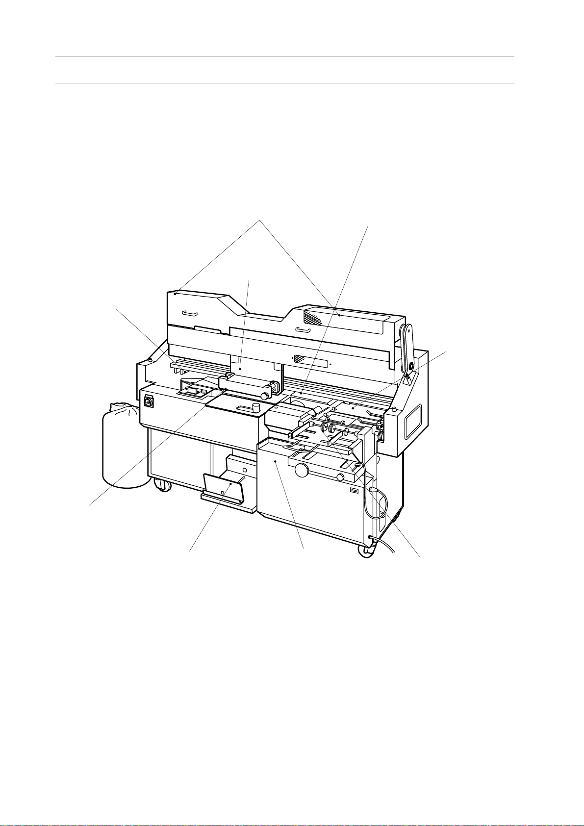
1-1 General View of BQ-260
Milling Unit
Safety Cover
Clamper Unit
Melt Tank Unit
Nipping Unit
Level Plate
Vertical Stacking Section
Control Panel
Cover Feeding Unit
(Option)
2
Page 9
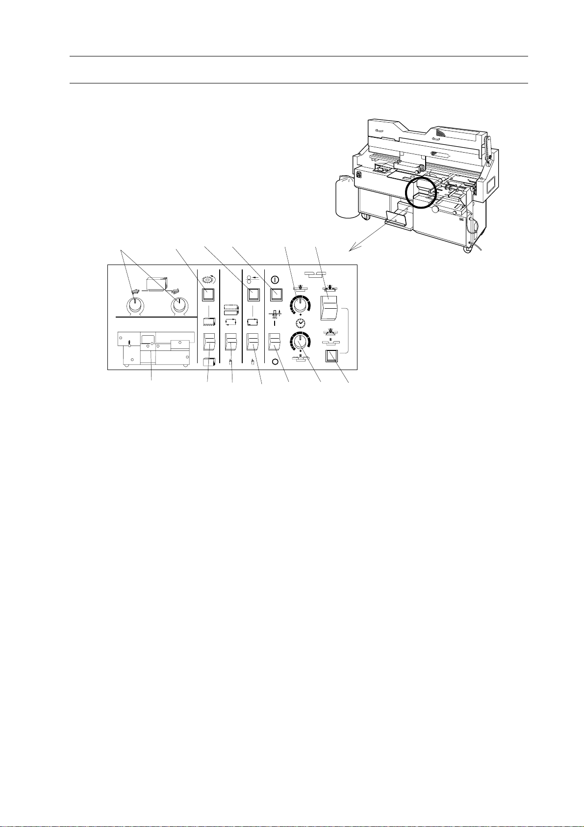
1-2 Control Panel
1 234 56
Trouble Monitor
1. Machine Parts Descriptions
7 8 9 10111213
1.Gluing Length Adjusting Knobs
Used to adjust spine glue length.
2.Milling Start Button
Used to start to rotate milling cutter.
3.Cover Single Feed Button
Used to feed one cover sheet from cover
feeder with automatic cover feeding
mode.
4.Nipper Up/Down Button
Used to raise or lower nipper unit for
setting up nipping unit.
5.Nipping Time Control Knob
Used to control nipping time.
6.Nipping Mode Select Switch
Used to select nipping mode. Three
different modes, With milling binding
mode, Signature binding mode and Pad
binding mode can be selected.
7.Trouble Monitor
(Please refer to next page.)
8.Milling Mode Select Switch
Used to select milling mode, with milling
or without milling.
9.Level Plate Mode Select Switch
Used to select reset mode of Level Plate
after one complete cycle of binding
automatic or manual.
10. Cover Feed Mode Select Switch
Used to select cover feed mode, automatic or manual
11.Clamper Pin On/OFF Switch
Used to turn on/off clamper pin which
holds stock in clamper when without
milling mode is selected..
12.Nipping Delay Time Control Knob
Used to control nipping delay time
length.
13.Pad Binding Lamp
This lamp turns on when pad binding
mode is selected.
3
Page 10
1. Machine Parts Descriptions
1-2 Control Panel
(1)
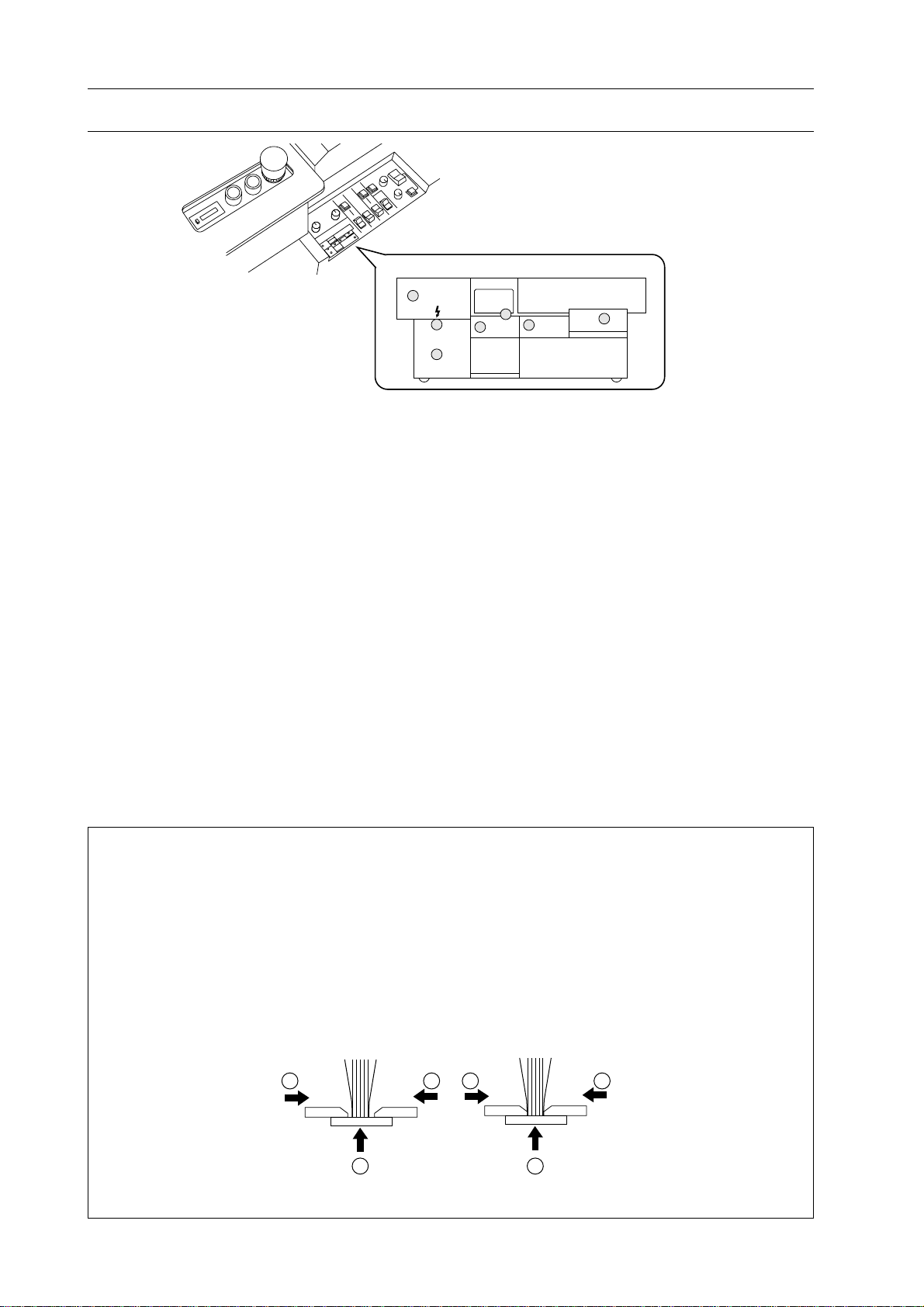
Trouble Monitor
(3)
(6)
Trouble Monitor
Indicates incorrect point on BQ-260.
When one of them turns on except power
lamp, BQ-260 can not be started.
Each LED turns on when :
(1) safety cover opens.
- Close safety cover.
(2) milling cutter does not rotate although
with milling binding mode is selected.
- Depress milling cutter start button to
rotate milling cutter.
(3) level plate opens.
- Depress start button to reset level plate.
(4) emergency stop switch is depressed.
- Pull up emergency stop switch to release it.
(7)
(2)
(5)
(4)
(5) glue is not ready for biding.
- Wait until glue will be melted.
(6) cover is not fed to stopper.
- Feed cover completely until it gets
stopped against stopper.
(7) main power is on.
NOTE : Difference of Nipper Movement
Nipping unit has two different movements, with milling binding mode and signature bind-
ing mode. In with milling binding mode, nipper plate raises at first and then front and back
nipper jaws nip stock. So, this binding mode is suitable for binding milled stock or cut sheet
stock. In signature binding mode, nipper plate and two nipper jaws raise and nip stock at
same time. So this binding mode is suitable for binding signature which spine is shaped
thicker because of folded edge. Book spine will be formed too sharp or destroyed when
spine is pressed at first as in with milling binding mode. Binding quality or book spine
shape bound with signature binding mode is not affected so much by folding.
2 211 1
1
With Milling Binding Mode Signature Binding Mode
4
Page 11
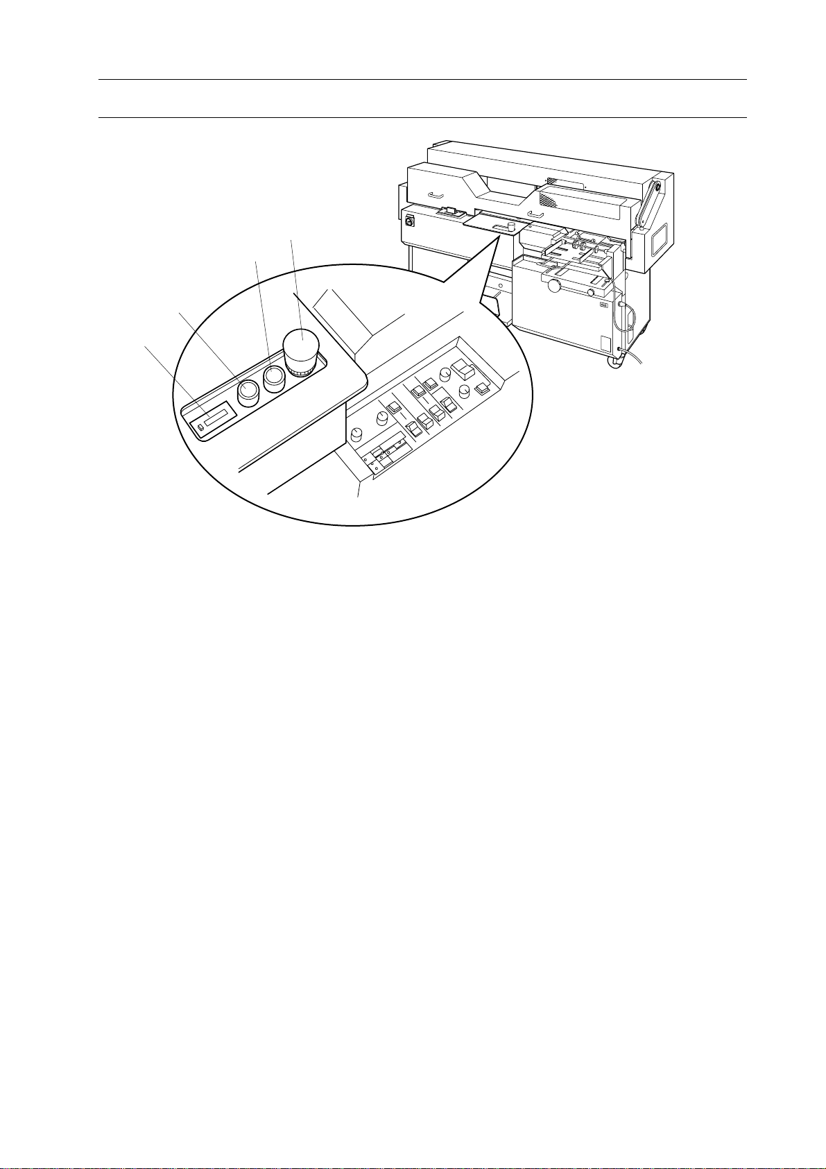
1-3 Operation Panel
4
3
2
1
1. Machine Parts Descriptions
1.Counter (with reset button)
Used to count amount of binding. When
reset button is set at far side, number in
counter can not be reset.
2.Level Plate Button
Used to open and reset level plate manually
when level plate switch is set at manual
operation mode.
3.Start Lamp and Start Button
Lamp indicates that BQ-260 is ready to
bind.
4.Stop Button
5
Page 12
1. Machine Parts Descriptions
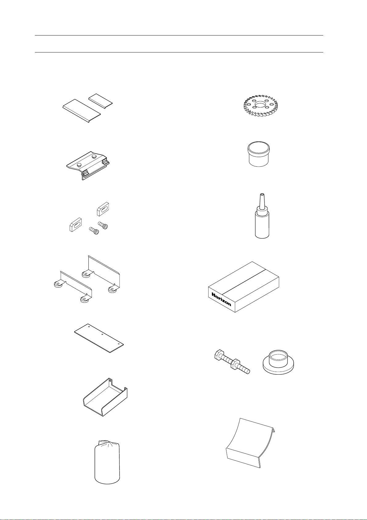
1-4 Accessories and Tools
Check all accessories are supplied with your BQ-260 when you open package.
1. Support Plates for Cover Feeder Unit
Large :1 pc
Small :1 pc
2. Small Cover Stopper (1 pc)
3. Small Cover Position Register (2 sets)
4. Clamper Support Guide
Large :1 pc
Normal : 1pc
8. Milling Cutter (1 pc)
9. Grease (1 pc)
10. Chain Oil (1 pc)
11. Hot Melt HM-110 (5 kg)
5. Space Plate (1 pc)
6. Drain for Glue Replacement (1 pc)
7. Dust Bag (1 pc)
H
M
-1
1
0
5
k
g
12. Mount Base with Leveling Bolt (3 sets)
13. Chute for small book (1 pc)
6
Page 13
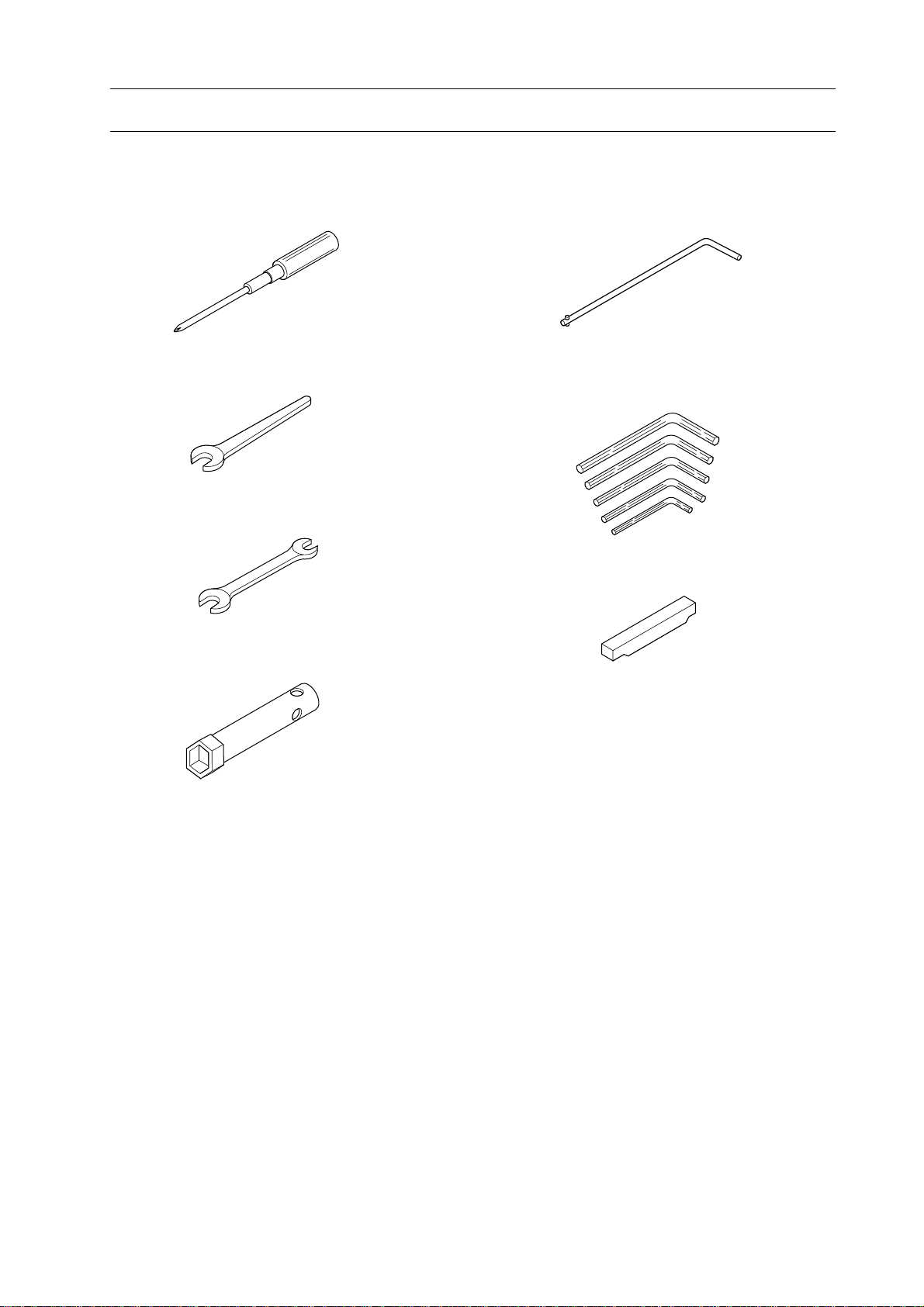
1-5 Accessory Tools
Check all tools supplied with your BQ-260 when you open package.
1. Machine Parts Descriptions
1. Screw Driver (1 pc)
2. Spanner (30 mm) (1 pc)
3. Spanner (13/17 mm) (1 pc)
4. Box Wrench ( 30 mm) (1 pc)
5. Special Wrench (1 pc)
6. Allen Wrench (2.5, 3, 4, 5, 6 mm)
(1 pc of each)
7. Roughening Cutter Height Gauge (1 pc)
.8
0
.5
0
7
Page 14

1. Machine Parts Descriptions
This page is intentionally left blank.
8
Page 15

2. Installation Instructions
2. Installation Instructions
2-1 Installation Instructions.......................................................................... 10
9
Page 16
2. Installation Instructions
2-1 Installation Instructions
2-1-1 Installing Place
This section shows condition of installing
place for BQ-260.
WARNING
Weights of BQ-260 is about 500 kg.
Pay attention enough to transportation.
BQ-260 could fall down or catch a
person with something like wall.
1. Select a flat, rigid floor free from vibra-
tion.
2. Select a place free from direct exposure
to sun light.
3. Select a place free from extremely high
temperature and humidity.
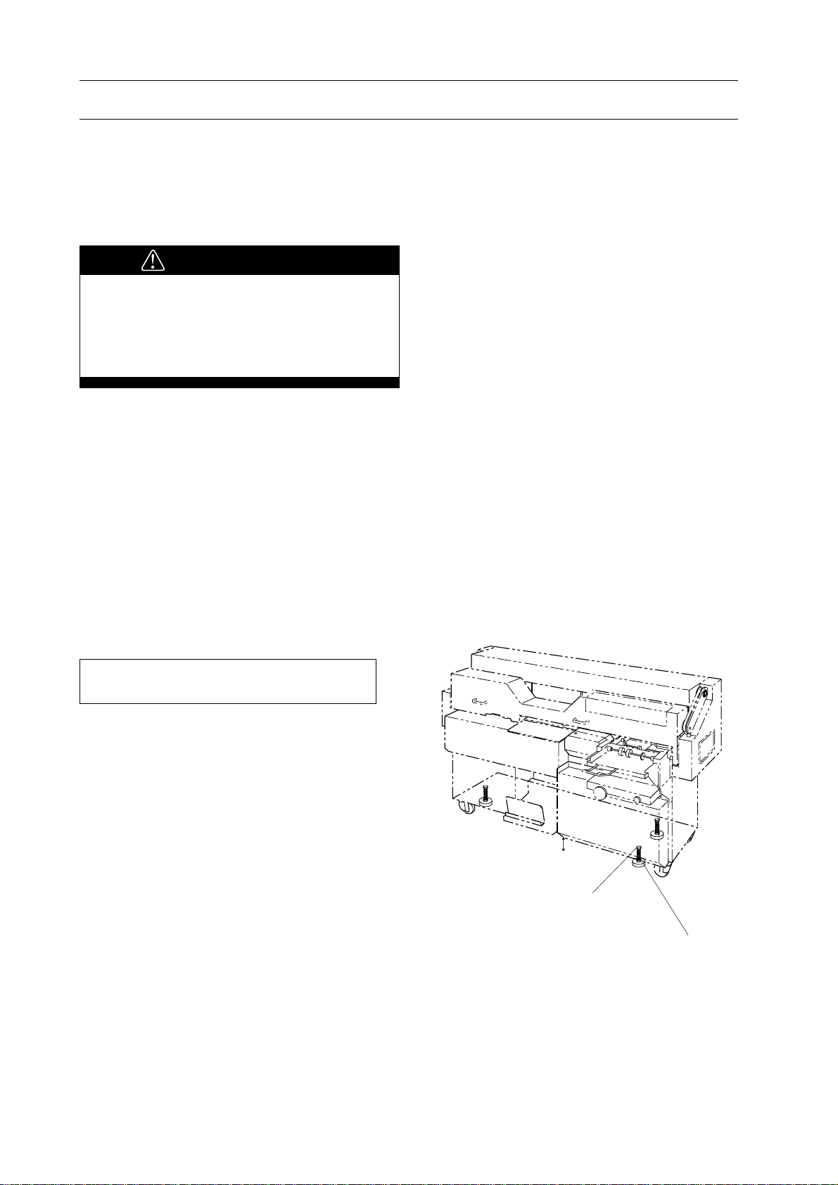
2-1-2 Installing BQ-260
This section shows how to install BQ-260.
Necessary Tools : Spanner (19 mm)
1. Place BQ-260 on installation place.
2. Place 3 mount base under levelling bolts.
3. Turn leveling bolts with spanner clock-
wise until bottom of BQ-260 is 120 mm in
height.
4. Fasten 3 lock nuts on 3 leveling bolts.
120 mm
Leveling Bolt
Mount
10
Page 17
2-1 Installation Instructions
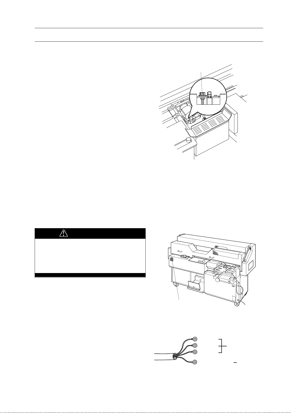
2-1-3 Releasing Transport Lock Nut
2. Installation Instructions
Melt Tank lock nut is installed to prevent
melt tank moving up and down during transportation.
1. Loosen melt tank lock nut.
NOTE
- It is not necessary to remove transport lock
nut. Remain it loosen.
- Remain height adjust bolt loosen unless
melt tank height adjustment is required.
2-1-4 Connecting Power Cord
Height Adjust Bolt
Lock
This section shows how to connect power
cord on BQ-260.
WARNING
- Be sure to depress stop button to
prevent sudden work of BQ-260.
- Confirm voltage and frequency to be
used on your BQ-260 are correct.
1. Depress stop button.
2. Make sure that power switch is off.
3. Turn off main power or breaker in your
shop.
4. Attach power cord to 3-phase power
source.
Main Switch
Blue
Brown 3-Phase
Black
11
Green/Yellow Ground
Page 18
2. Installation Instructions
2-1 Installation Instructions
5. Turn on main power or breaker in your
shop.
6. Turn on power switch on BQ-260.
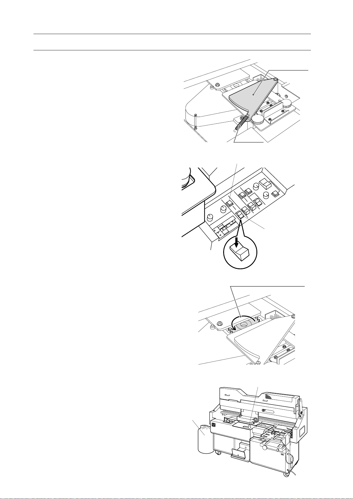
7. Remove the spring and open the shutter
plate.
8. Pull up stop button.
9. Depress milling mode select switch to
far side to select with milling mode.
10. Depress milling start button.
- Blower will start at the same time.
11. Depress milling mode select switch to
near side to stop the milling cutter, watching the rotating milling cutter from above.
- Check the rotating direction of the milling
cutter.
- The milling cutter should rotate counterclockwise.
Shutter Plate
Spring
Milling Start Button
Milling Mode
Select Switch
With Milling Mode
Normal Rotating Direction
12. If the milling cutter rotates clockwise,
stop immediately and perform as follows:
- Turn off power on BQ-260 and main
power or breaker in your shop.
- Change wiring on 3-phase terminal and
perform step 5 through 12.
13. Depress stop button after connecting
power cord correctly.
wat
Stop button
Dust Bag
12
Page 19

3. Before Starting Operation
3. Before Starting Operation
3-1 Safety Device Function Check................................................................ 14
3-2 Every Day Check Up............................................................................... 18
13
Page 20
3. Before Starting Operation
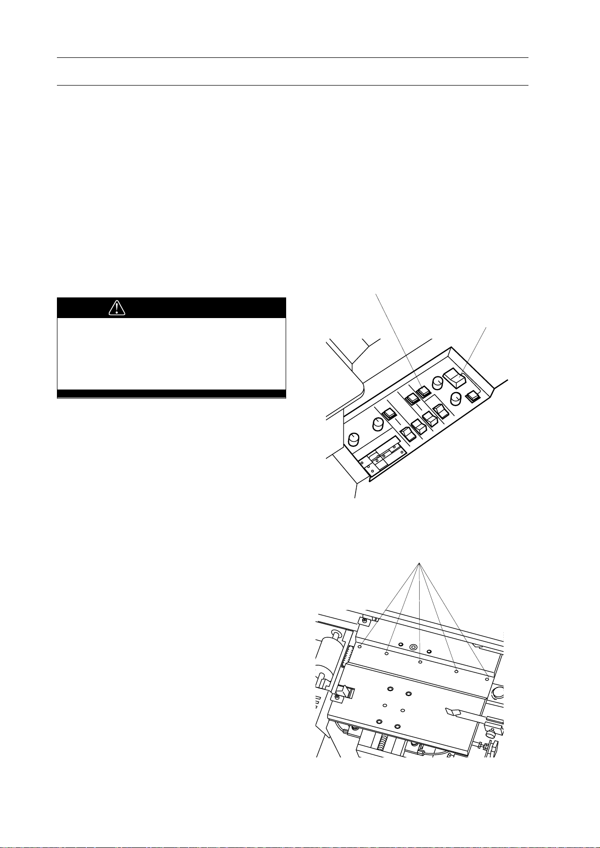
3-1 Safety Device Function Check
This section shows how to check safety device
function. Check all safety device function
before starting operation on BQ-260.
3-1-1 Stop Button
WARNING
Do not touch clamper while clamper is
moving. Moving clamper can cause
severe personal injury.
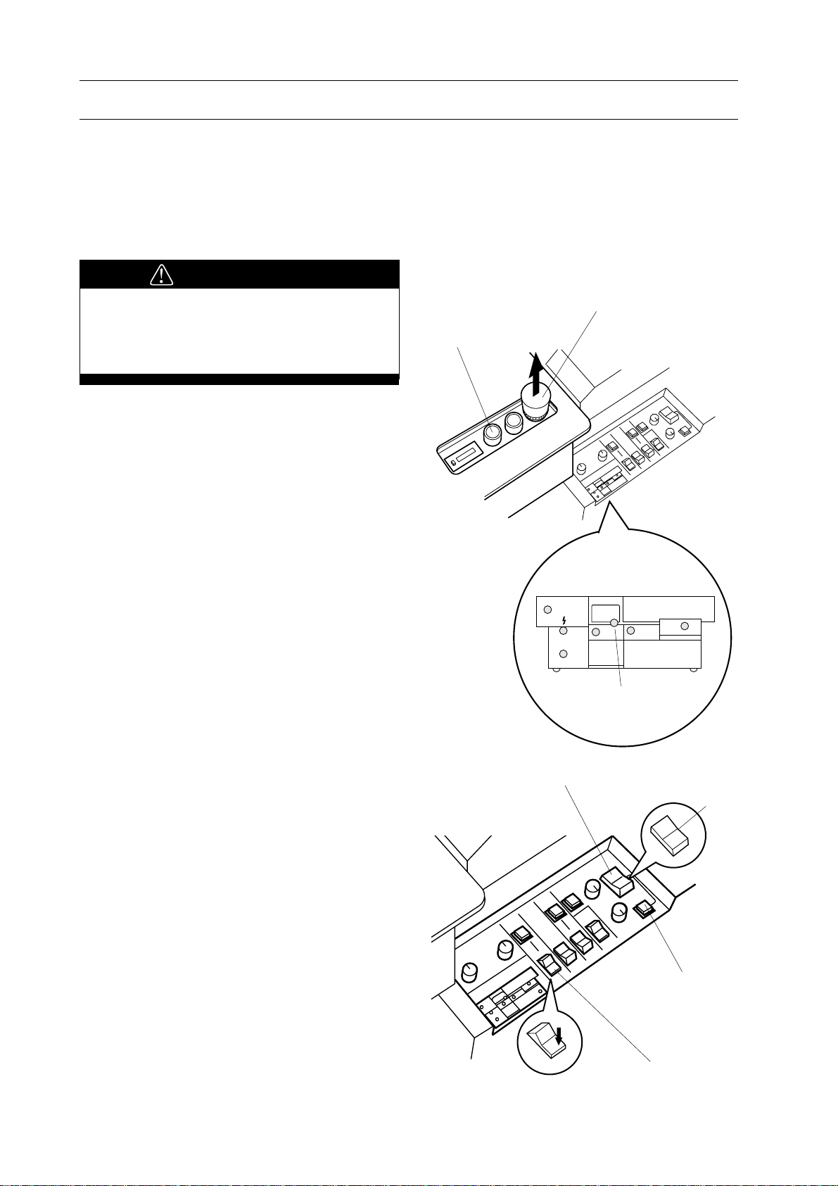
1. Pull up stop button. LED on monitor for
stop button turns off.
Stop Button
Start Button
2. Set nipping mode select switch to center
position to select pad binding mode.
- Pad binding lamp on control panel turns
on to indicate that pad binding is selected.
3. Select without milling mode with milling
mode select switch.
- Confirm lamp on start button is ON.
NOTE
Depress level plate control button when start
lamp is not on.
LED for Stop Button
Nipping Mode Select Switch
Pad Binding
Lamp
Near Side
Milling Mode
Select Switch
Center
14
Page 21
3-1 Safety Device Function Check
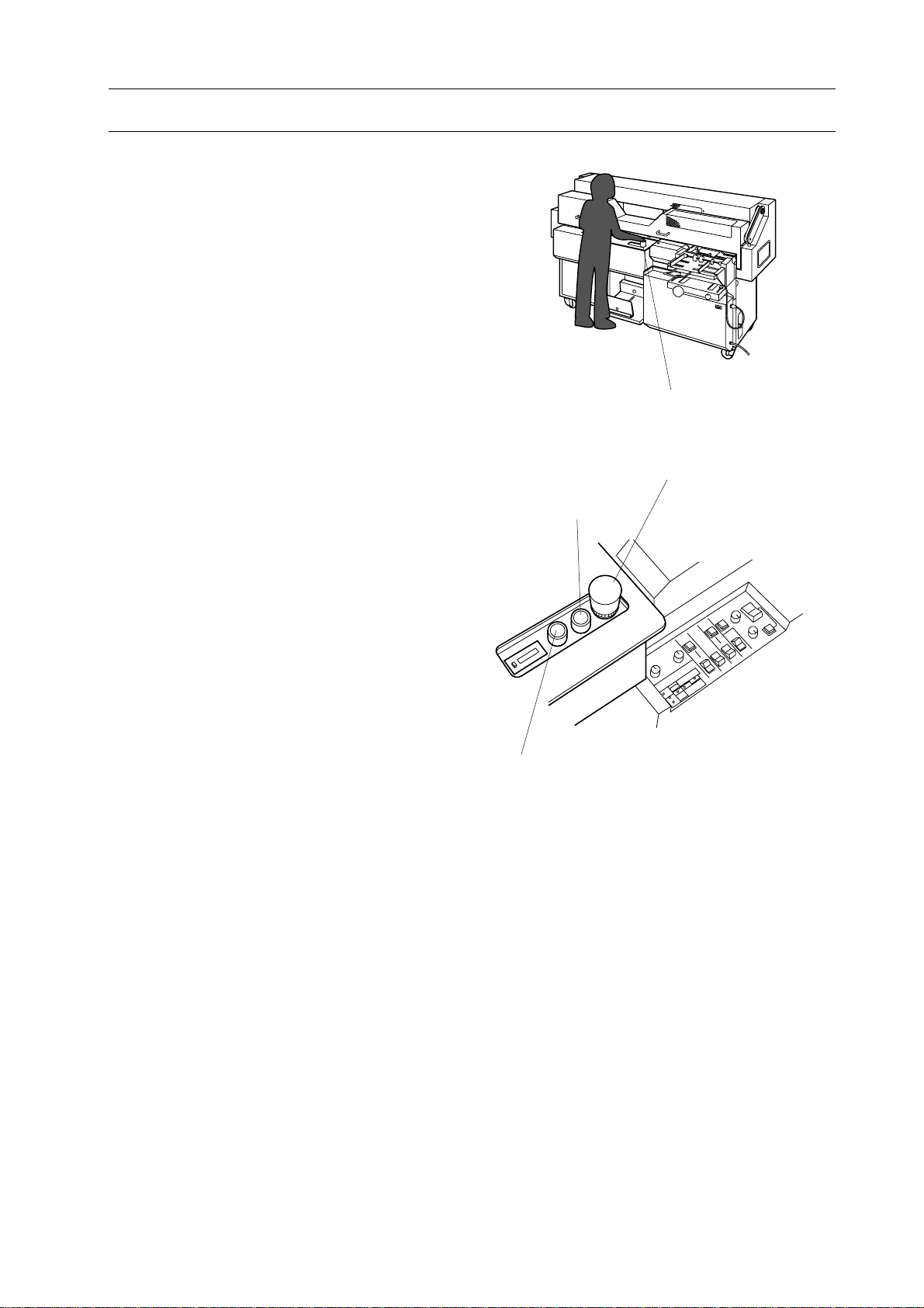
4. Check emergency stop function.
- Stand in front of operation panel.
- Hold top of stop button with your right
hand to prepare to depress stop button
immediately.
- Depress start button and depress stop
button 1 second after start button was
depressed.
- Clamper will stop in a moment to show
that emergency stop function works
correctly.
NOTE
When clamper does not stop in a moment
even if stop button is depressed, turn off main
power and call your local dealer.
3. Before Starting Operation
Stop Button
Stop Button
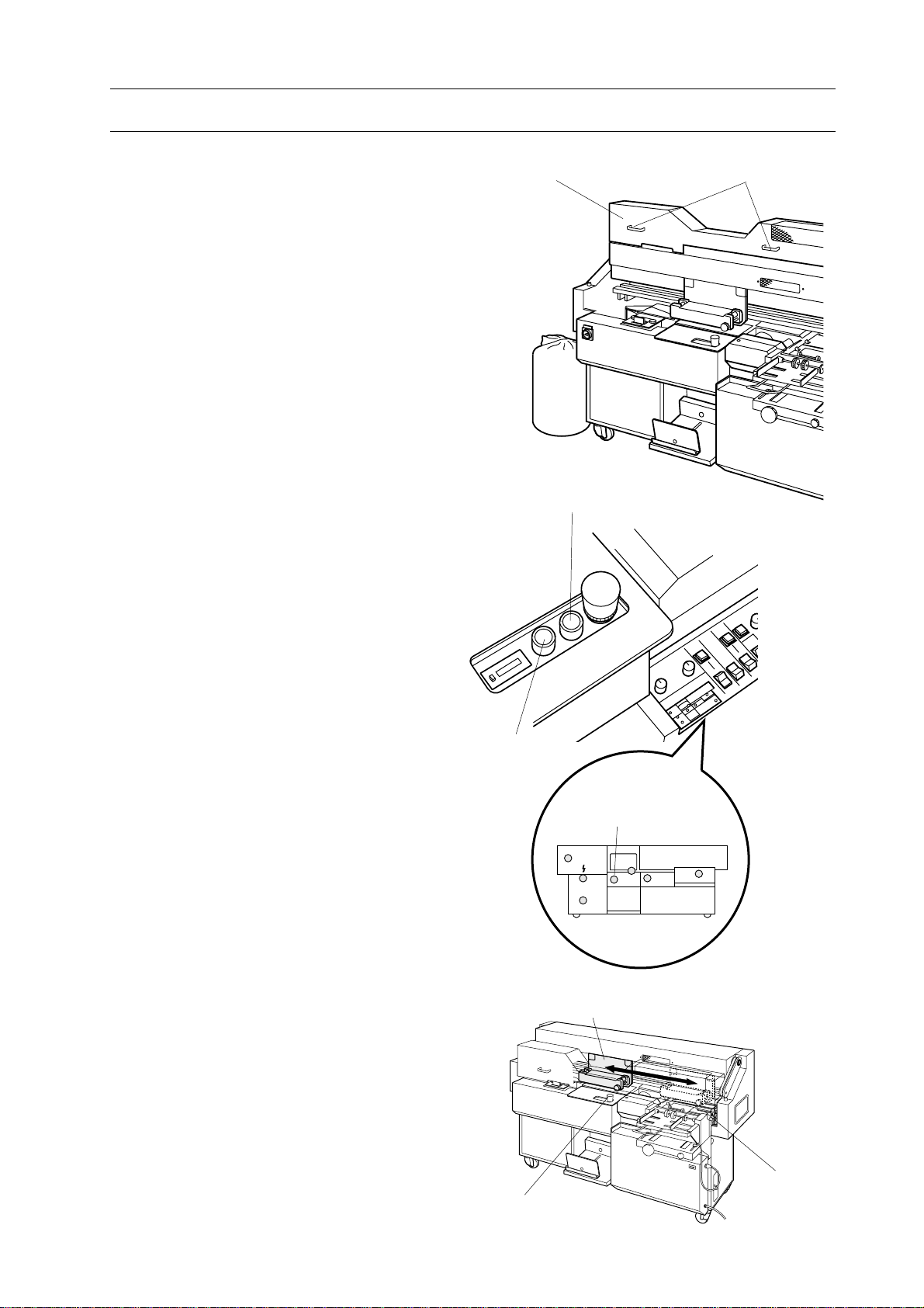
5. Move clamper to home position.
- Pull up stop button.
- Depress start button to move clamper to
its original position. Clamper will stop
over nipping unit for 10 seconds.
6. Reset level plate.
- When clamper returns to home position,
depress level plate button once to reset
level plate.
- Start button will turn on to indicate
level plate is reset.
7. Depress stop button to prevent BQ-260
works suddenly by mistake.
Start Button
Level Plate Button
15
Page 22

3. Before Starting Operation
3-1 Safety Device Function Check
This section shows how to check safety device
function. Check all safety device function
before starting operation on BQ-260.
3-1-2 Safety Cover
WARNING
Do not touch clamper while clamper is
moving. Moving clamper can cause
severe personal injury.
1. Pull up stop button. LED on monitor for
stop button turns off.
Stop Button
Start Button
2. Set nipping mode select switch to center
position to select pad binding mode.
- Pad binding lamp on control panel turns
on to indicate that pad binding is selected.
3. Select without milling mode with milling
mode select switch.
- Confirm lamp on start button is ON.
NOTE
Depress level plate control button when start
lamp is not on.
LED for Stop Button
Nipping Mode Select Switch
Pad Binding
Lamp
Near Side
Milling Mode
Select Switch
Center
16
Page 23
3-1 Safety Device Function Check
3. Before Starting Operation
4. Check safety cover function.
- Stand in front of operation panel.
- Hold handle on safety cover with your
both hand to prepare to open safety cover
immediately
- Depress start button and open safety cover
1 second after start button was depressed.
- Clamper will stop in a moment to show
that safety cover function works correctly.
NOTE
When clamper does not stop in a moment
even if safety cover is opened, turn off main
power and call your local dealer.
5. Move clamper to home position.
- Close safety cover.
- Depress start button to move clamper to
its original position. Clamper will stop
over nipping unit for 10 seconds.
Safety Cover
Start Button
Handles
6. Reset level plate.
- When clamper returns to home position,
depress level plate button once to reset
level plate.
- Start button will turn on to indicate
level plate is reset.
7. Depress stop button to prevent BQ-260
works suddenly by mistake.
Level Plate
Button
Stop Button
LED for Stop Button
Clamper
Cover Feeder
Unit
17
Page 24
3. Before Starting Operation
3-2 Every Day Check Up
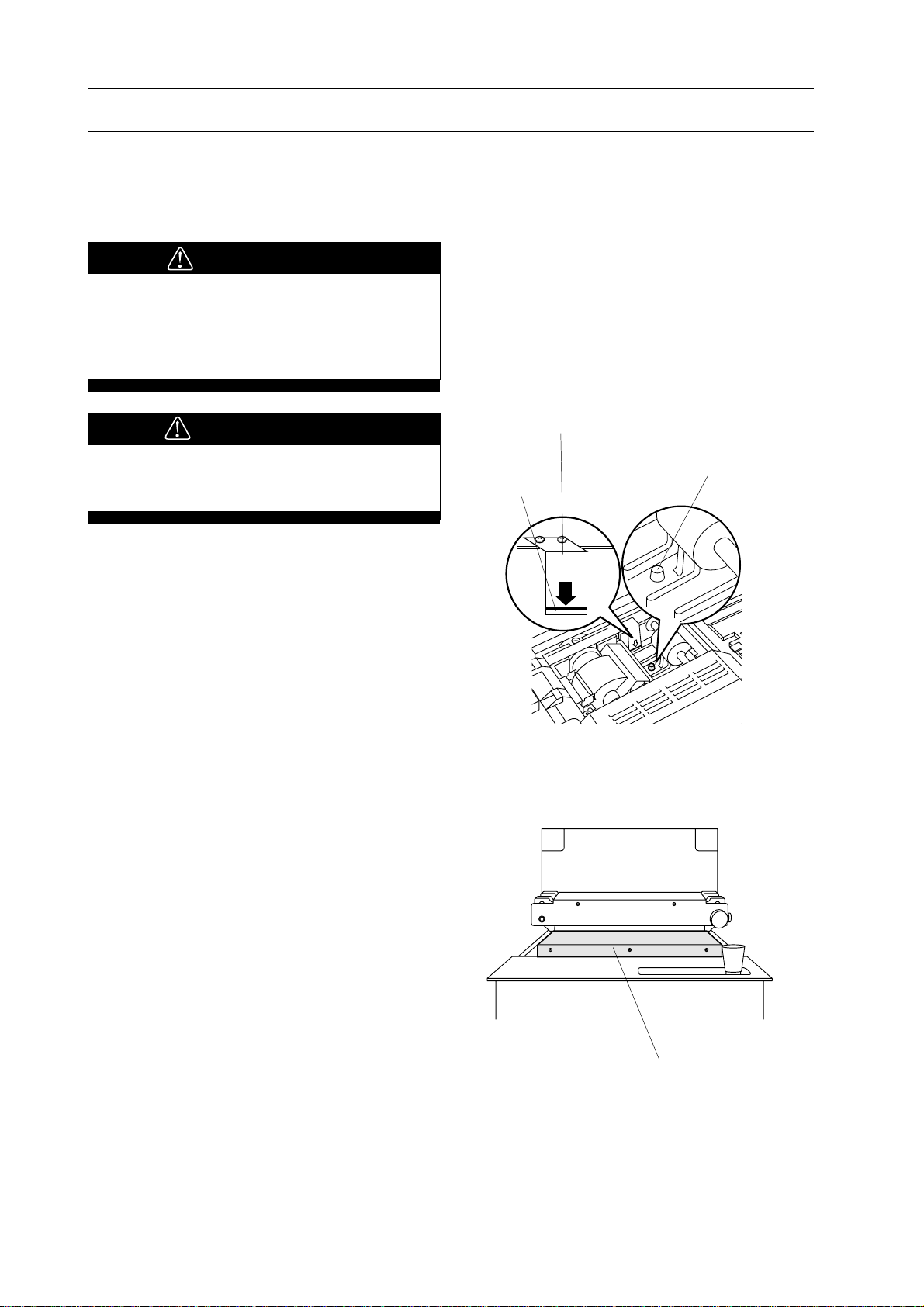
3-2-1 Glue Level Check
Before start binding, glue level in melt tank
must be checked.
WARNING
Keep off your hands or fingers from
melt tank. Melt tank is heated up to
around 200˚C. High temperature can
cause severe skin burn.
CAUTION
Do not supply glue more than Red Line
on melt tank glue level scale.
NOTE
Check glue level when glue is melted.
1. When glue lower limit mark in melt tank
appears, glue level is not enough for binding.
NOTE
See "7-1 Glue Supply" (Page 54) when you
supply glue.
3-2-2 Level Plate Cleaning Check
Melt Tank Glue Level Scale
Glue Lower Limit Mark
Red Line
CAUTION
Keep glue level
below red line.
Before start binding, surface of level plate
must be cleaned.
1. Check level plate with your eyes
whether paper dust or glue stick on level
plate.
NOTE
See "7-2-2 Level Plate Clean Up" (Page 56)
when cleaning of level plate is necessary.
Level Plate
18
Page 25
3-2 Every Day Check Up
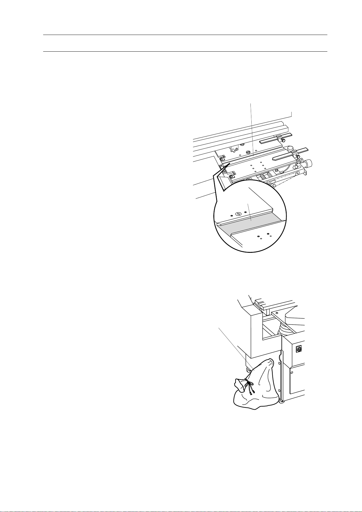
3-2-3 Nipper Unit Check
Before start binding, surface of nipper plate
and nipper jaw must be cleaned.
1. Check nipper plate and nipper jaws with
your eyes whether paper dust or glue stick
to nipper plate and nipper jaws.
NOTE
See "7-2-1 Nipping Plate and Nipper Jaw
Clean Up" (Page 55 ) when you clean nipper
unit.
3. Before Starting Operation
Nipper Plate
Nipper Plate
3-2-4 Dust Bag Check
Before start binding, dust bag must be empty.
1. Check dust bag with your hands whether
it is empty or not.
NOTE
See "7-3-1 Dust Bag Clean Up" (Page 58 )
when you clean dust bag.
Dust Bag
19
Page 26

3. Before Starting Operation
This page is intentionally left blank.
20
Page 27

4. Set Up BQ-260
4. Set Up BQ-260
4-1 Nipper Unit Set Up .................................................................................. 21
4-2 Clamper Unit Set Up............................................................................... 26
4-3 Milling Unit Set Up ................................................................................. 27
4-4 Vertical Stacker Unit Set Up .................................................................. 29
4-5 Melt Tank Unit Set Up............................................................................ 30
4-6 Operation Switches Set Up ..................................................................... 32
4-7 Test Binding ............................................................................................. 33
21
Page 28
4. Set Up BQ-260
4-1 Nipper Unit Set Up
NOTE
When your binding job is pad binding
(without cover), nipper unit set up is not
necessary to perform. Select pad binding
mode with nipping mode select switch. Then
proceed to "4-2 Clamper Unit Set Up" in
Page 26.
4-1-1 Nipper Unit Set Up for Stock Thickness
This section shows how to adjust nipping
width against stock thickness.
Nipper Up/Down Button
WARNING
Do not touch melt tank unit when
adjusting nipper unit. Melt tank is
heated up around 200˚C. High temperature can cause severe skin burn.
1. Select either with milling or without
milling binding mode by nipping mode
select switch.
Near Side : for signature binding
Far Side : for with milling binding
Center : for pad binding
2. Depress nipper up/down button to raise
nipper plate. Nipper plate stop at upper
position.
NOTE
- Nipper jaw's width must be adjusted when
nipper unit is at upper position.
- When nipper up/down button is depressed
with nipper being up position, nipper unit will
be down.
- Nipper is at lower position when 5 screws
on nipper plate appear.
Nipping Mode
Select Switch
Screws
3. Depress stop button.
22
Page 29
4-1 Nipper Unit Set Up
4. Set Up BQ-260
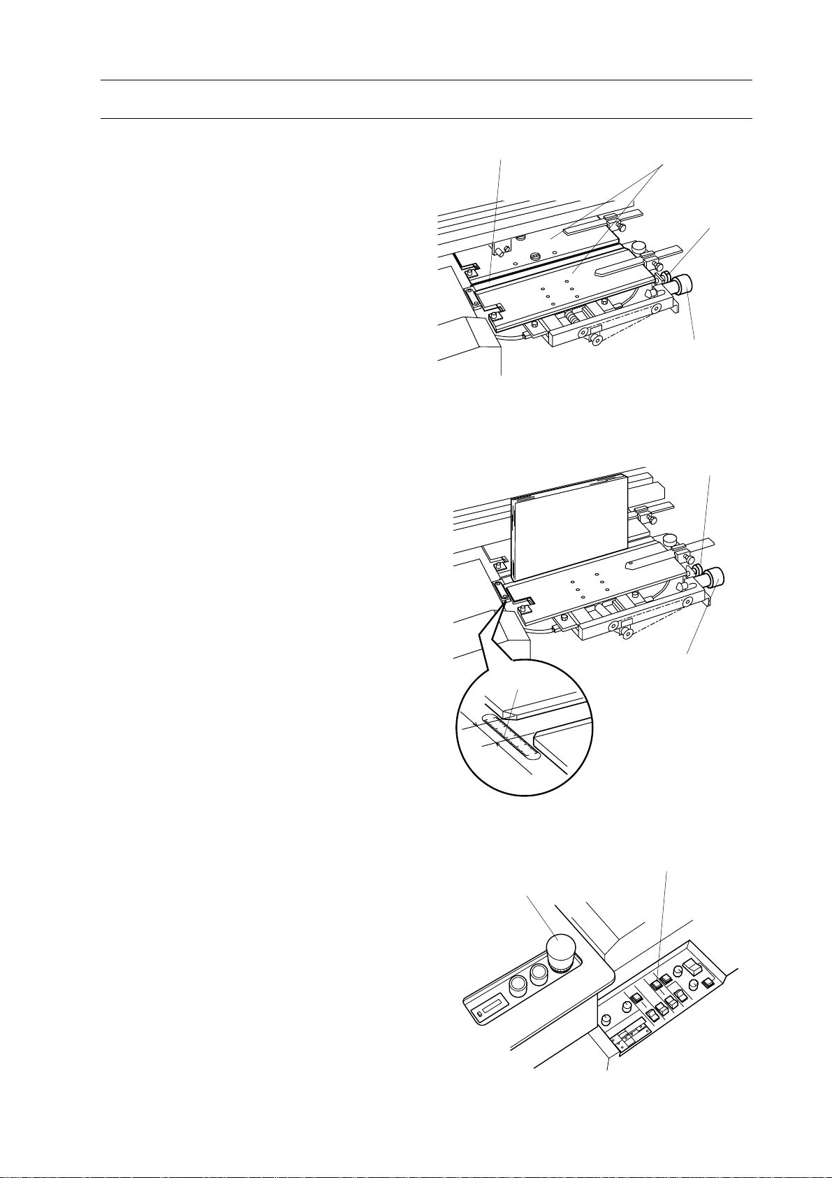
4. Hold 2 handles on safety cover with your
both hands and open safety cover.
5. Turn fix knob counterclockwise to
unlock nipping width adjusting knob.
6. Turn nipping compression adjusting
knob counterclockwise to open nipper jaws
until stock can be placed on nipper plate.
7. Place stock on nipper plate.
8. Turn nipping width adjusting knob
clockwise to nip stock.
9. Read scale on nipping unit. This mea-
surement will be used for setting up
clamper.
Nipping Plate Nipper Jaws
Lock Knob
Nipping Width
Adjusting Knob
Lock Knob
Stock
10. Slightly turn nipping width adjusting
knob counterclockwise to release the stock.
- Nipping width adjusting knob must be
turned back clockwise to secure the
adjusted width of nipper jaws.
11. Turn fix knob Clockwise to lock nipping
width adjusting knob.
12. Close safety cover.
13. Pull up stop button.
14. Depress nipper up/down button to lower
nipper unit.
15. Depress stop button to prevent BQ-260
works suddenly by misoperation.
Scale
Stop Button
Nipping Width
Adjusting Knob
Cover Single Feed Button
23
Page 30

4. Set Up BQ-260
4-1 Nipper Unit Set Up
4-1-2 Cover Positioning Set Up
This section shows how to adjust cover stopper and guide.
1. Pull up stop button.
2. Depress nipper up/down button to raise
nipper unit. Nipper unit stops at upper
position.
NOTE
Set up cover position when nipper unit is at
lower position.
Nipper Up/Down Button
3. Hold handles on safety cover with both
hands and open safety cover.
4. Prepare one cover sheet and mark center
point inside both edges of cover sheet.
5. Loosen two fix knobs for movable cover
guide.
6. Slide cover guides right to provide space
to place cover on nipper unit.
Cover Registers
Center Point
Movable Cover Guides
Fix Knobs
24
Page 31

4-1 Nipper Unit Set Up
4. Set Up BQ-260
7. Place cover inside up on nipper unit, so
that far side and left side slightly touch
cover stopper and cover registers.
NOTE
Register side of cover must be placed against
cover registers.
8. Turn cover stopper adjusting knob so
that marks on cover is positioned just on
center of nipper plate.
NOTE
Push or pull cover at the same time when
cover stopper is adjusted.
9. Slide movable cover guide against cover
to fix cover position. And then fasten fix
knobs for movable cover guide.
Cover Stopper Adjusting Knob
Movable Cover Guides
Cover
Cover Registers
Nipping Plate
Cover Stopper
Lock Knob
NOTE
- Clearance between cover and movable cover
guide must be less than 0.5 mm.
- Check whether cover does not bend or does
not have play more than 0.5 mm.
10. Close safety cover.
11. Depress nipper up/down button to lower
nipper unit.
NOTE
Cover can be fed only when nipper unit is at
lower position.
0.5 mm
Movable
Cover Guide
Cover
0.5 mm
Nipper Up/Down Button
25
Page 32

4. Set Up BQ-260
4-2 Clamper Unit Set Up
This section shows how to adjust clamper
unit opening.
WARNING
Depress stop button before setting up
clamper. Sudden start of clamper can
cause severe personal injury.
1. Depress stop button.
2. Hold two handles on safety cover with
your both hands and open safety cover.
3. Loosen lock knob on clamper.
Stop Button
Scale
4. Turn clamper opening adjusting knob to
adjust with the same measurement as in
nipper unit adjustment.
5. Fasten fix knob on clamper firmly.
6. Close safety cover.
NOTE
- Attach book guide (Accessory) on safety
cover when longer stock is placed.
Thinner book binding .. on clamper
Thicker book binding .. on safety cover
- Select guide large or small according to
stock size.
Clamper Opening
Adjusting Knob
Lock Knob
Book Guide
26
Page 33

4-3 Milling Unit Set Up
NOTE
When milling is not required on your binding, milling unit set up is not necessary to
perform.
Select without milling mode and proceed to
"4-4 Cover Feeder Unit Set Up" (Page 29).
4-3-1 Milling Guide Set Up
This section shows how to adjust milling
guide position.
1. Depress emergency stop switch.
4. Set Up BQ-260
Safety Cover
Stop Button
2. Loosen two lock knobs on front milling
guide.
3. Hold holder on stock thickness caliper
and open stock thickness caliper more than
stock thickness.
4. Place stock in stock thickness caliper.
NOTE
Use stock which will be bound.
5. Hold holder on stock thickness caliper
and push it to stock so that caliper guides
hold stock.
6. Fasten two lock knobs on front milling
guide firmly.
Holder Lock Knobs
Lock Knobs
Stock Thickness Caliper
Stock
Milling Guide
7. Take out stock from stock thickness
caliper.
27
Page 34

4. Set Up BQ-260
4-3 Milling Unit Set Up
4-3-2 Milling Depth Set Up
WARNING
Be sure to depress stop button before
adjusting milling depth and do not
touch milling cutter. Sharp cutter can
cause severe personal injury.
Necessary Tools : Allen Wrench (6 mm)
Pipe Wrench and Special
Wrench
1. Depress stop button.
2. Open safety cover.
3. Loosen lock screw on milling depth
adjusting bolt with allen wrench (6 mm).
Safety Cover
Stop Button
4. Adjust milling depth.
- Turn milling depth adjusting bolt with
pipe wrench to select milling depth.
- Align number on scale with pointer bar to
select required milling depth.
NOTE
- Unit on scale is mm.
- Milling depth is adjusted to 2 mm before
shipment.
5. Fasten fix screw on milling depth adjust-
ing bolt with allen wrench.
6. Close safety cover.
Pointer Bar
Milling Depth
Adjusting Bolt
28
Lock Screw
Scale
Allen Wrench
Pipe Wrench
Fix Screw
2.1
21
3
2.5
Page 35

4-4 Vertical Stacker Unit Set Up
This section shows how to adjust vertical
stacker.
1. Push stopper on vertical stacker unit
fully inside.
4. Set Up BQ-260
Stopper
29
Page 36

4. Set Up BQ-260
4-5 Melt Tank Unit Set Up
This section shows how to set up glue film
thickness and glue temperature.
WARNING
- Depress stop button before adjusting
melt tank.
- Ware gloves on your hands when you
set up melt tank unit. Melt tank is
heated up to around 200˚C. High temperature can cause severe skin burn.
CAUTION
Do not turn glue film thickness adjust
screw until glue is ready for binding.
Necessary Tool : Allen Wrench (5 mm)
1. Depress stop button.
2. Open safety cover. And then open melt
tank cover.
Stop Button
30
Melt Tank Cover
Page 37

4-5 Melt Tank Unit Set Up
3. Turn glue film thickness adjust screw
with allen wrench to point number 1.5 on
scale.
NOTE
Unit on scale is mm. Standard thickness of
glue film is 1.5 mm.
4. Close melt tank cover.
1.5
4. Set Up BQ-260
Scale
2
0.5
1
5. Turn glue temperature adjust knob to
select glue temperature.
NOTE
- Unit for temperature used on glue tempera-
ture indicator is centigrade degree.
- Standard temperature for glue is 180
degrees.
- Glue applied on book spine will be dry
quicker when you set glue temperature
lower. Low glue temperature is recommended
for applying thick glue film.
6. Pull up stop button.
Melt Tank Cover
Glue Temperature
Adjust Knob
Stop Button
31
Page 38

4. Set Up BQ-260
4-6 Operation Switches Set Up
This section shows how to set each switch on
operation panel.
1. Select nipping mode with nipping mode
select switch.
Far Side : With milling binding
Cut sheet binding
Near Side : Without milling binding
Signature binding
Center : Pad binding (without
cover)
Nipping Mode
Select Switch
2. Set nipping time.
- Turn nipping time control knob and
nipping delay time control knob fully
counterclockwise.
3. Select cover feed mode with cover feed
mode select switch.
Far side : Automatic feed
Near side : Manual feed
4. Select level plate reset mode with level
plate reset mode select switch.
Far side : Automatic Reset
Near side : Manual Reset
(After booklet is removed by hand, reset
level plate with level plate button.)
Far Side
Nipping Time
Control Knob
Cover Feed Mode Select Switch
Gluing Length Adjusting Knob
Nipping Delay Time
Control Knob
Near Side
5. Select milling mode with milling mode
select switch.
Far side : With Milling
Near side : Without Milling
6. Set both gluing length adjusting knobs at
12 o'clock.
Level Plate Reset
Mode Select Switch
Milling Mode Select Switch
32
Page 39

4-7 Test Binding
4-7-1 Test Binding for With Milling Binding
Test binding is necessary to confirm each
unit is set up properly.
1. Prepare stock for test binding.
NOTE
Stock for test binding must be same stock as
your job.
2. Confirm that cover is fed on nipping unit
and LED for cover on monitor is off.
4. Set Up BQ-260
Cover Single Feed Button
NOTE
When cover is not fed properly on nipping
unit and LED for cover on monitor is on, set
up cover so that cover edge touches to stopper.
3. True up stock and insert stock into
clamper. Left side of stock must touch
register shaft in clamper.
NOTE
Left side of stock must be register side. Spine
of stock must face down.
LED for Cover
Clamper
33
Page 40

4. Set Up BQ-260
4-7 Test Binding
4-1 When with milling mode is selected,
depress milling start button.
- Lamp in milling start button will turn off
and milling cutter will start rotating.
- Blower pump will start at same time and
dust bag swells with air.
4-2 When without milling mode is selected,
lamp in milling start button will not be on.
5. Depress start button.
- Confirm that lamp on start button is on
and then depress start button.
- Clamper will start for binding and returns
to its home position (start position) after
binding.
Milling Start Button
Level Plate Button
Start Button
Stop Button
6. Confirm that book is ejected at vertical
stacker unit after binding finished.
7. Check binding.
- When binding result does not satisfy your
requirement, perform "4-1" to "4-7" (page
22 to 34) again to readjust each unit on
binder.
8. Depress stop button.
9. Take out book from vertical stacker unit.
Vertical Stacker Unit
34
Page 41

4-7 Test Binding
4-7-2 Pad Binding
Test binding is necessary to confirm each
unit is set up properly.
1. Prepare stock for test binding.
NOTE
Stock for test binding must be same as your
job.
4. Set Up BQ-260
2. True up stock and insert stock into
clamper. Left side of stock must touch
register shaft in clamper.
NOTE
Left side of stock must be register side for
cover and stock. Spine of stock must face
down.
3-1 When with milling mode is selected,
depress milling start button.
- Lamp on milling start button will turn off
and milling cutter start rotating.
- Blower pump will start at same time and
dust bag swells with air.
3-2 When without milling mode is selected,
lamp in milling start button will not be on.
4. Depress start button.
- Confirm that lamp on start button is on
and then depress start button.
- Clamper will start for binding and returns
to its home position (start position) after
padding.
Clamper
Milling Start Button
Stop Button
5. Take out book from clamper and check
binding.
- When binding result does not satisfy your
requirement, perform "4-1" to "4-7" (page
22 to 35) again to readjust each unit on
binder.
6. Depress level plate button to reset level
plate.
7. Depress stop button.
Start Button
Level Plate Button
35
Page 42

4. Set Up BQ-260
This page is intentionally left blank.
36
Page 43

5. Operation Procedure
5. Operation Procedure
5-1 With Cover Binding Operation.............................................................. 38
5-2 Pad Binding.............................................................................................. 39
37
Page 44
5. Operation Procedure
5-1 With Cover Binding Operation
This section shows binding operation for with
cover binding.
1. Pull up stop button.
2. Depress milling start button.
NOTE
When without milling binding mode is selected, milling start button is not necessary to
depress.
Stop Button
Milling Start Button
3. True up stock and insert stock into
clamper. Left side of stock must touch
register shaft in clamper.
NOTE
Left side of stock must be register side. Spine
of stock must face down.
4. Confirm that lamp on start button is on
and then depress start button.
Clamper
Level Plat Button
38
Start Button
Page 45

5-1 With Cover Binding Operation
5-1 Followings are process of binding (with
milling).
1) Stock is clamped with clamper and
transported to milling unit and milled off
spine.
2) Stock is transported to home position and
clamper is automatically opened on level
plate to rejog stock.
3) Stock is applied glue on melt tank unit.
4) Stock applied glue is transported to
nipping unit. Nipping unit raises, sticks
cover to stock spine and nips them
strongly.
5. Operation Procedure
5) Stock formed spine is transported to
home position through over lowered melt
tank unit. Cover for next binding is fed on
nipping unit at same time.
6) Stock is released from clamper and falls
into vertical stacker unit.
5-2 Followings are process of binding (with-
out milling).
1) Stock is clamped with clamper and
transported to melt tank unit.
2) Glue is applied on spine at melt tank
unit.
3) Stock applied glue is transported to
nipping unit. Nipping unit raises, sticks
cover to stock spine and nips them
strongly.
4) Stock formed spine is transported to
home position through over lowered melt
tank unit. Cover for next binding is fed on
nipping unit at same time.
5) Stock is released from clamper and falls
into vertical stacker unit.
39
Page 46

5. Operation Procedure
5-2 Pad Binding
This section shows binding operation for pad
binding.
1. Pull up stop button.
2. When milling is required, depress mill-
ing start button.
Stop Button
Milling Start Button
3. True up stock and insert stock into
clamper. Left side of stock must touch
register shaft in clamper.
NOTE
Left side of stock must be register side. Spine
of stock must face down.
4. Confirm that lamp on start button is on
and then depress start button.
Clamper
Start Button
Level Plate Button
40
Page 47

5-2 Pad Binding
5-1 Followings are process of pad binding
(with milling).
1) Stock is clamped with clamper and
transported to milling unit and milled off
spine.
2) Stock is transported to home position and
clamper is automatically opened on level
plate to rejog stock.
3) Stock is applied glue on melt tank unit.
4) Stock is stopped over nipping unit for
several seconds to dry glue.
5) Stock is transported to home position
through over lowered melt tank unit.
5. Operation Procedure
6) Stock is released from clamper.
5-2 Followings are process of pad binding
(without cover)
1) Stock is clamped with clamper and
transported to melt tank unit.
2) Stock is applied glue on melt tank unit.
3) Stock is stopped over nipping unit for
several seconds to dry glue.
4) Stock is transported to home position
through over lowered melt tank unit.
5) Stock is released from clamper.
41
Page 48

5. Operation Procedure
This page is intentionally left blank.
42
Page 49

6. Special Binding Method
6. Special Binding Method
6-1 Small Size Binding................................................................................... 44
6-2 To Increase Glue Film Thickness .......................................................... 48
6-3 To Adjust Finish Condition of Spine..................................................... 52
43
Page 50

6. Special Binding Method
6-1 Small Size Binding
6-1-1 Register Shaft Position Adjustment
This section shows how to set up register
shaft when spine length of stock is shorter
than 130 mm (5.1").
WARNING
Depress stop button when you replace
register bar position. Clamper can
cause severe personal injury.
Necessary Tool : Special Wrench
(Accessory)
1. Depress stop button.
2. Remove register shaft in clamper with
special wrench.
NOTE
Do not fall removed register bar while it is
removed.
3. Fix register shaft with special wrench on
position indicated in drawing.
Stop Button
Clamper
Special Wrench
44
Register Shaft Position for
Smaller Size Binding
Page 51

6-1 Small Size Binding
6-1-2 Cover Position Register Block Installation
This section shows how to install register
block when spine length of cover is shorter
than 130 mm (5.1").
WARNING
Depress stop button when you attach
cover position register blocks. Nipper
unit can cause severe personal injury.
NOTE
Cover position register block is not required
for pad binding.
6. Special Binding Method
Necessary Tools : Allen Wrench (3 mm)
1. Depress stop button.
2. Attach cover position register blocks on
nipper.
NOTE
- Attach cover position register blocks so that
beveled corner faces to right-near side.
- Fix cover position register blocks so that it
is parallel with nipper jaw edge.
- Fix cover position register blocks so that
screw comes at center of groove.
- The blocks can be slid right and left within
10 mm.
Stop Button
Nipper Jaws
45
Cover Position
Register Block
Beveled Corner
Page 52

6. Special Binding Method
6-1 Small Size Binding
6-1-3 Small Cover Stopper Installation
This section shows how to install small cover
stopper.
WARNING
- Depress stop button when small cover
stopper is installed. Nipper can cause
severe personal injury.
- Turn off power switch when back
cover is opened.
Necessary Parts : Small cover stopper
Cover Stopper Adjusting Knob
1.
Depress stop button.
2. Turn cover stopper adjusting knob fully
clockwise.
3. Hold back cover with your hand and
loosen two lock screws.
4. Open back cover.
5. Fix small cover stopper on cover stopper
with two lock screws.
NOTE
- When small cover stopper is installed, cover
sensor recognizes as if cover sheet is always
placed. Confirm whether cover is fed properly
on nipper unit before you start binding.
- Cover must be fed manually when small
cover stopper is mounted on cover stopper.
Lock Screws
Back Cover
Lock Screws
Small
Cover
Stopper
Sensor
6. Close back cover and fix with two lock
screws.
46
Page 53

6-1 Small Size Binding
6-1-4 Shooter Attachment
This section shows how to install shooter
when spine length of stock is shorter than
160 mm.
NOTE
Any type of binding requires shooter when
stock spine length is shorter than 160 mm.
Necessary Parts : Shooter (Accessory)
1. Depress stop button.
6. Special Binding Method
Stop Button
2. Pull out stopper on vertical stacker unit
fully to near side.
3. Hung shooter on holes on stacker.
4. Keep stopper at the near side position.
Stopper
Shooter
47
Page 54

6. Special Binding Method
6-2 To Increase Glue Film Thickness
6-2-1 Spacer Plate Attachment
This section shows how to install spacer plate
on level pate to increase glue film thickness.
WARNING
Do not touch clamper when start button is depressed. Clamper can cause
severe personal injury.
Necessary Tool : Screw Driver
1. Pull up stop button.
- LED for stop button on monitor turns off.
2. Set nipping mode select switch at middle
position to select pad binding mode.
- Pad binding lamp turns on.
Stop Button
Level Plate Button
Start Button
LED for Stop Button
3. Depress milling mode select switch to
select with milling mode.
4. Confirm lamp on start button turns on.
NOTE
Depress level plate control button when lamp
on start button does not turn on.
Milling Mode
Select Switch
48
Center
Nipping Mode
Select Switch
Far Side
Page 55

6-2 To Increase Glue Film Thickness
5. Stand in front of operation panel.
6. Place your right hand on stop button.
7. Depress stop button when clamper
reaches to nipping section.
Level Plate Button
6. Special Binding Method
Stop Button
Start Button
8. Confirm level plate is clean.
NOTE
If it is not clean, see "7-2-2 Level Plate Clean
Up" (Page 56) and clean level plate.
9. Loosen three screws on level plate with
screw driver.
Screws
49
Level Plate
Page 56

6. Special Binding Method
6-2 To Increase Glue Film Thickness
10. Place spacer plate on level plate and fix
spacer plate with three screws.
11. Pull up stop button.
- LED for stop button on monitor turns off.
Level Plate Button
Spacer Plate
Stop Button
12. Depress start button to move clamper its
original position.
13. Depress level plate button once to reset
level plate.
- Start lamp will turn on to indicate level
plate is reset.
14. Depress stop button.
Start Button
LED for Level Plate
50
Page 57

6-2 To Increase Glue Film Thickness
6-2-2 Melt Tank Height Adjustment
This section shows how to adjust melt tank
height to increase glue film thickness by
lowering a melt tank unit.
WARNING
Put gloves on your hands when you set
up melt tank unit height. Melt tank is
heated up to around 200 degrees. High
temperature can cause severe skin
burn.
Necessary Tools : Allen Wrench (5 mm)
Screw Driver
6. Special Binding Method
1. Depress stop button.
2. Open melt tank cover.
3. Turn clockwise melt tank up/down screw
with Allen wrench until melt tank rises 1 to
2 mm.
4. Loosen fix screw on spacer until spacer
can be moved.
5. Turn spacer clockwise to insert it under
stopper. Confirm spacer is inserted under
stopper completely and then fasten fix
screw with screw driver.
6. Loosen melt tank up/down screw with
Allen wrench.
Melt Tank Cover
Fix Screw
Spacer
Stopper
Melt Tank Up/down Screw
7. Close melt tank cover.
51
Page 58

6. Special Binding Method
6-3 To Adjust Finish Condition of Spine
This section shows how to adjust finish
condition of spine by changing nipping
height or angle when the spine corner is too
sharp, or spine corner is round.
NOTE
Sheet quality and glue application thickness
influence the finish condition of spine.
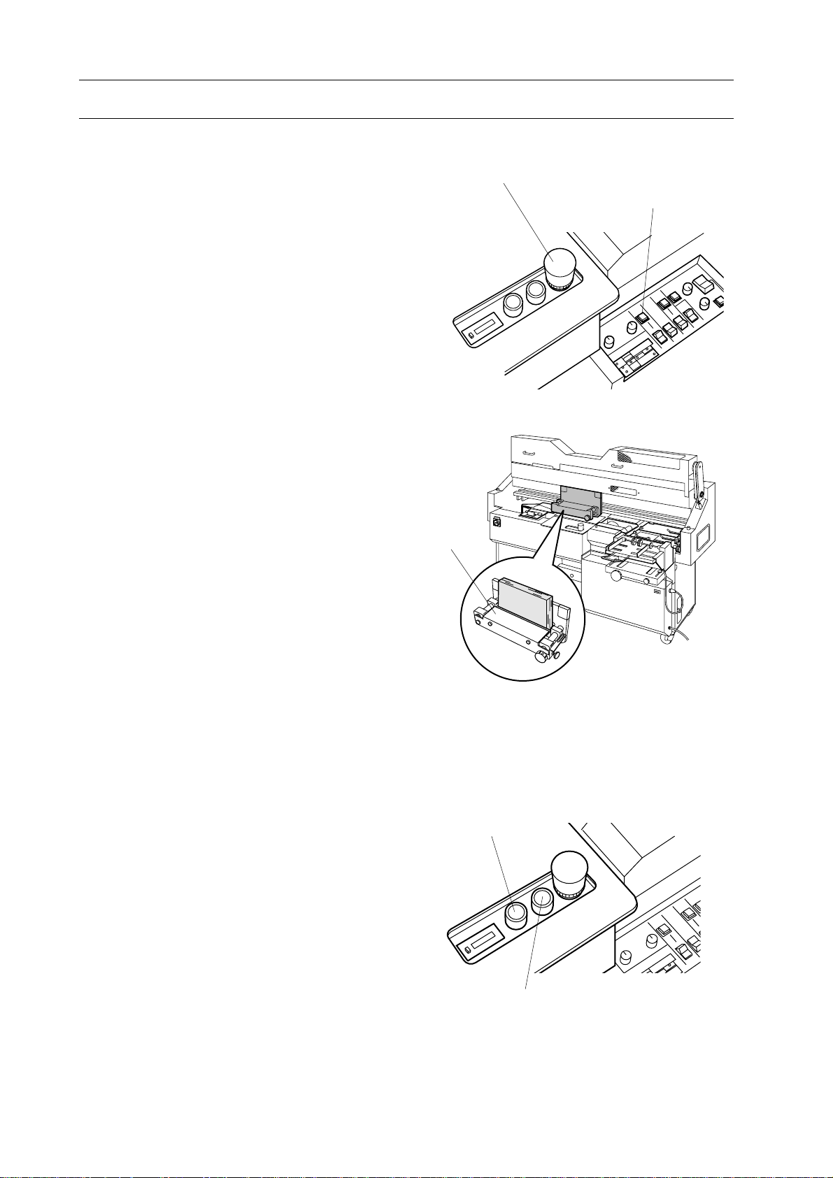
1. Move cover feeding unit to the front side
to provide access space under nipping unit.
2. Turn adjust bar to the required direction
with spanner (17 cm).
Lower Section of
Nipping Unit
Adjust Bar
Dial
Hand
3. Make sure of the finish condition by test
binding. After that, set cover feeding unit.
Dial Number
0 : Standard
- : Nipper lowers by turning adjust bar counterclockwise (arrowed direction)
and spine becomes rounder.
+ : Nipper rises by turning adjust bar clockwise and spine becomes sharper.
Adjustment of the
Right Side of Nipper
Adjustment of the
Left Side of Nipper
52
Page 59

7. After Binding Finish
7. After Binding Finish
7-1 Glue Supply.............................................................................................. 53
7-2 Clean Up While Power On ..................................................................... 55
7-3 Clean Up after Power Off....................................................................... 58
7-4 Clean Up after Power Off....................................................................... 59
53
Page 60

7. After Binding Finish
7-1 Glue Supply
Glue must be supplied in melt tank when
binding finished.
WARNING
- Put gloves on your hands when you
supply glue in melt tank which is
heated up to around 200 degrees. High
temperature can cause severe skin
burn.
- Depress emergency stop switch before
supplying glue.
1. Open malt tank cover.
2. Place glue on supply area in melt tank.
NOTE
- Supply glue into melt tank piece by piece
not to supply glue over maximum glue level.
- Glue level must be lower than RED line on
glue level indicator.
- Use only Horizon Glue (HM-110).
3. Close melt tank cover.
Melt Tank Cover
Melt Tank Glue Supply Area
54
Page 61

7-2 Clean Up While Power On
7-2-1 Nipping Plate and Nipper Jaw Clean Up
Nipping plate or nipper jaws must be cleaned
after binding finished.
WARNING
- Depress stop button before cleaning.
- Put gloves on your hands. You might
unexpectedly touch melt tank which is
heated up to around 200 degrees. High
temperature can cause severe skin
burn.
7. After Binding Finish
Clamper
Stop Button
Necessary Tool : Cloth
1. Depress stop button.
2. Confirm clamper stops over level plate.
3. Confirm nipping unit is at lower point.
NOTE
- If nipping unit is at upper position, release
emergency stop, close safety cover and depress nipping unit up/down button once to
lower nipping unit.
- When nipping unit is at lower position, five
screws on nipping unit appear.
Nipper Plate
Screws
Nipper Up/Down Button
Stop Button
4. Wipe off dust such as glue or paper dust
on nipping plate and nipper jaws with
cloth.
55
Page 62

7. After Binding Finish
7-2 Clean Up While Power On
7-2-2 Level Plate Clean Up
Level plate must be cleaned after binding
finished.
WARNING
- Depress stop button to prevent personal injury after step 4.
- Ware gloves on your hands. You
might unexpectedly touch melt tank
which is heated up to around 200
degrees. High temperature can cause
severe skin burn.
Necessary Tool : Cloth
1. Pull up stop button.
2. Select pad binding mode.
- Set nipping mode select switch to center.
Pad binding lamp in start button will turn
on.
Stop Button
Start Button
Nipping Mode Select Switch
Center
56
Pad Binding Lamp
Page 63

7-2 Clean Up While Power On
3. Move clamper
- Depress start button to move clamper to
nipping unit. And then depress stop
button when clamper come over nipping
unit.
NOTE
Application roller in melt tank keeps to rotate
even if stop button is depressed. (for about 30
seconds)
4. Clean level plate with cloth.
7. After Binding Finish
Stop Button
Start Button
Level Plate
5. Pull up stop button.
6. Depress start button to return clamper to
home position.
7. Depress level plate control button once
to reset level plate after clamper returned to
home position.
8. Depress stop button.
NOTE
Occasionally application roller in melt tank
unit keeps to rotating.
Stop Button
Start Button
Level Plate
Button
57
Page 64

7. After Binding Finish
7-3 Clean Up after Power Off
7-3-1 Dust Bag Clean Up
Dust bag must be empty after binding finished.
1. Remove dust bag and dump dust from
dust bag.
2. Knot strings of dust bag on exhaust duct
on BQ-260.
Dust Bag
7-3-2 Vertical Stacker Unit Clean Up
Stacker must be cleaned after power off.
1. Pull out stacker fully to outside.
2. Clean stacker with soft cloth.
Exhaust Duct
Strings
Stacker
58
Page 65

7-4 Clean Up after Power Off
7-4-1 Milling Unit Clean Up
Milling unit must be cleaned after power off.
7. After Binding Finish
WARNING
Do not touch milling cutter or roughening cutter with your hands or fingers.
Sharp cutter can cause severe personal
injury.
1. Open safety cover.
2. Hold holder on front milling guide and
pull front milling guide fully to near side.
Safety Cover
3. Clean paper dust on milling unit surface
with vacuum cleaner.
4. Close safety cover.
Holder
Front Milling Guide
59
Page 66

7. After Binding Finish
7-4 Clean Up after Power Off
7-4-2 Gluing Length Sensor Clean Up
Gluing length sensor must be cleaned after
power off.
WARNING
- Clean up gluing length sensor after
melt tank cooled down.
- Ware gloves on your hand to prevent
accidental touch on warm melt tank
unit.
1. Open safety cover.
Glue Length Sensor
2. Clean gluing length sensor with soft
cloth or brush.
3. Close safety cover after cleaning.
7-4-3 Cover Sensor Clean Up
Cover sensor must be cleaned after power off.
1. Open back cover.
2. Turn cover stopper adjusting knob to
move cover stopper most backward position.
Cover Stopper Sensor
Cover Stopper
3. Clean cover stopper sensor with soft
brush.
4. Close back cover after cleaning.
60
Page 67

8. maintenance
8. Maintenance
8-1 Once A Month.......................................................................................... 62
8-2 As Required.............................................................................................. 63
61
Page 68

8. Maintenance
8-1 Once A Month
8-1-1 Lubrication on Melt Tank Unit
This section shows required maintenance
once in a month.
WARNING
Ware gloves on your hands when melt
tank is lubricated. Melt tank is heated
up to 200˚C.
1.Open safety cover.
2. Lubricate marked parts of melt tank unit
with a supplied melt tank chain oil.
8-1-2 Greasing on Clamper Rail
Wipe off all dust on clamper rail.
1.
2. Grease both back and front of clamper
rail.
Lubrication Points
Clamper Rail
8-1-3 Oiling on Nipper Unit
1. Pull oil pump lever once to lead oil to
slide part of nipper unit.
NOTE
It is not necessary to push oil pump lever.
Lever will move back automatically.
Oil Pump Lever
62
Page 69

8-2 As Required
8. maintenance
8-2-1 Milling Cutter Replacement
Continuous use of dull milling cutter will
effect on binding finish quality. Replace
milling cutter as required.
WARNING
- Turn off main power before replacing
milling cutter.
- Ware gloves on your hands when
milling cutter is replaced. Cutter will
cause severe personal injury.
Necessary Tools : Double-ended Spanner
(13 mm)
Allen Wrench (4 mm)
Thick Cloth
Hook Bolt
Spring White Cutter Guard
Front Milling Guide Rear Milling Guide
1. Turn off main power.
2. Access to milling cutter.
- Open safety cover.
- Remove spring on white cutter guard
from hook bolt.
- Remove both front and rear milling
guides.
3. Remove milling cutter.
- Place thick cloth to hold milling cutter.
- Loosen four fix screws on milling cutter
and remove milling cutter.
4. Install new or resharpened milling cutter
with reverse order of removing.
5. Install milling guides.
- Install rear milling guide so that guide
aligned with three positioning pins.
- Install front milling guide.
- Hook spring on white cutter guide to
cover milling section.
Thick Cloth
Hook Spring
Allen Wrench
Milling Cutter
Positioning Pins
63
Page 70

8. Maintenance
8-2 As Required
8-2-2 Roughening Cuter Replacement
Continuous use of dull roughening cutter will
effect on binding finish quality. Replace
roughening cutter as required.
WARNING
- Turn off main power before replacing
milling cutter.
- Ware gloves on your hands when
roughening cutter is replaced. Cutter
will cause severe personal injury.
Necessary Tools : Allen Wrench (5 mm)
Thick Cloth
Milling Cutter
1. Turn off main power.
2. Access to roughening cutter.
- Open safety cover.
- Open front milling guide.
- Remove spring on white cutter guard
from hook bolt.
3. Open P.C.B. cover.
- Remove four fix screws and tilt down
P.C.B. cover.
4. Depress release button to release brake
on milling cutter motor.
Spring
White Cutter Guard
Front Milling Guide
5. Turn milling cutter slowly by hand to
access to roughening cutter lock screw.
P.C.B. Cover
64
Release Button
Page 71

8-2 As Required
6. Remove roughening cutter.
- Hold tip of roughening cutter with thick
cloth.
- Loosen roughening cutter lock screw with
allen wrench.
- Pull out roughening cutter.
NOTE
- Spring under roughening cuter will jump
out. Remove roughening cutter slowly.
- Roughening cutter is reversible parts.
Roughening Cutter
Height Gauge
8. maintenance
Allen Wrench
7. Install new or reversed roughening
cutter.
- Push down roughening cutter with thick
cloth and fix lock screw.
- Place roughening cutter height gauge over
roughening cutter.
NOTE
Select either 0.5 mm or 0.8 mm for required
height of cutter.
- Loosen lock screw once. Roughening
cutter will move up. Then fix lock screw
firmly.
8. Close all safety and P.C.B. cover.
Roughening
Cutter
Roughening
Cutter
Screw
Spring
65
Page 72

8. Maintenance
8-2 As Required
8-2-3 Glue Draining
This section shows how to drain glue in melt
tank. Deteriorated glue because of long
heating will cause decrease of adhesive
strength.
WARNING
Ware gloves on your hands when glue
is drained. Melted glue temperature is
200˚C. It can cause sever skin barn.
NOTE
Glue can only be drained when it is melted.
1. Melt glue.
- Turn on main power and wait until LED
for melt tank on monitor turns off.
2. Attach glue drain.
- Remove melt tank cover.
- Open control box.
- Attach glue drain under drain plate.
3. Provide a box for receiving glue (2 liter
capacity).
4. Drain glue
- Remove drain plug. Glue will come out
from melt tank.
- Fasten drain plug after all glue are
drained.
Met Tank Cover Control Box
Drain Plate
Glue Drain
5. Close covers
- Remove glue drain.
- Close control box , melt tank cover and
safety cover.
Box
66
Page 73

9. Installation of Suction Cover Feeder CF-260
9. Installation of Suction Cover Feeder CF-260
(Optional Equipment)
9-1 Before You Begin..................................................................................... 68
9-2 Set Up and Operation ............................................................................. 71
9-3 Trouble Shooting ..................................................................................... 76
9-4 Installation of BQ-260 ............................................................................. 78
67
Page 74

9. Installation of Suction Cover Feeder CF-260
9-1 Before You Begin
9-1-1 Specifications
Model Name CF-260
Maximum Cover Size 500 ~ 380 mm (19.7" x 15")
Minimum Cover Size 260 ~ 180 mm (10.2" x 7.1")
Cover Pile Height 100 mm (3.9")
Cover Thickness 80 to 300 gsm
Power Source 3-phase 200 V 50/60 Hz, 220 V 60 Hz, 400 V 50 Hz 0.65A
Power Consumption 0.4 kw
Motor 0.2 kw x 1, 25 w x 1, 15 w x 1
Machine Dimension 700 (W) x 690 (D) x 840 (H) mm
Machine Weight 110 kg (243 lb)
The machine design and specifications are subject to change without any notice.
9-1-2 Machine Descriptions and Functions
Operation Panel
Front Guide
Back Guide
Side Guide
68
Table Height Adjusting Knob
Skew Adjusting Knob
Table Forward/Backward Handle
Power Switch
Page 75

9. Installation of Suction Cover Feeder CF-260
9-1 Before You Begin
9-1-3 Descriptions and Functions of Operation Panel
Table Up Button
This button is used to raise table, and
to stop lowering table.
Sucker Bar Inching Button
This button is used to inch sucker bar.
Sucker bar stops at home position by
pressing this button coutinuously.
Compressor OFF Button
This button is used to turn off feed roller and
air pump.
Compressor ON Button
This button is used to turn on
feed roller and air pump.
Power Lamp
This lamp turns on when
power is on.
One Cycle Button
This button is used to operate sucker bar
one cycle. Sucker bar stops at home
position after one cycle.
Table Down Button
This button is used to lower table, and
to stop raising table.
69
Page 76

9. Installation of Suction Cover Feeder CF-260
9-1 Before You Begin
9-1-4 Tools and Accessories
Cover (M032435-00) 1 pcSucker (M014852-02) 14 pcs
Back Guide (M032433-00) 1 pc
Support Plate(S) (A933418-00) 1 pc
Support Plate(L) (A933416-00) 1 pc
(S)
Roller Cleaner(A933417-00) 2pcs
(L)
Adapter (A303401-00) 1 pc
Sucker Close/Open Tool 1 pc
(4010658-00)
Cover Sheet Holder(M032810-00) 1pc
Screw(M002000-01) 3pcs Sub Table 1pc
70
Page 77

9-2 Set Up and Operation
9-2-1 Cover Piling
This procedure shows cover piling before
starting binding.
WARNING
Do not touch moving parts parts. Moving parts may cause severe personal
injury.
CAUTION
Do not place books, tools and so on
under table. They may cause machine
damage.
9. Installation of Suction Cover Feeder CF-260
Table Lower Button
Front Guide
1. Turn on power switch.
-Power lamp turns on.
2. Press table lower button.
-Table lowers and stops at lowest position.
3. Pile covers so that covers touch front
guide and side guide.
NOTE
- Straighten covers before piling. Wavy or
curled cover will cause inferior feeding such
as misfeed.
- Do not pile covers more than 10 cm.
4. Place back guide at right corner of cover
on table.
5. Press table up button.
-Table rises and stops at feeding position.
Side Guide
Back Guide
Bin Up Button
One Cycle Button
6. Press one cycle button. Sucker bar
moves forward and then stops.
71
Page 78

9. Installation of Suction Cover Feeder CF-260
9-2 Set Up and Operation
9-2-2 Open/Close of Sucker Valve
This procedure shows how to set up suckers
for deifferent size of cover.
1. Pick up suckers which are going to suck
cover.
NOTE
Do not pick up suckers which does not completely placed on cover.
2. Open those sucker valve with sucker
open/close tool.
Close other sucker valve.
Sucker Valve
9-2-3 Cover Feeder Position Set Up
This procedure shows cover feeder set up
according to cover size.
1. Set up nipper referring to "4-1 Nipper
Unit Set Up"(page 22).
2. Make sure that nipper is at lower posi-
tion.
3. Place one cover on nipper.
4. Turn table forward/backward handle
until the clearance between cover and feed
roller is 2 to 3 mm.
9-2-4 Support Plate Set Up
This procedure shows how to set support
plate.
Feed Roller
2 ~ 3 mm
Cover
Nipper
1. Select suitable size of support plate and
place it on nipper so that the clearance
between cover feeder and support plate is
20 mm.
NOTE
When the size of cover is B4 (10.1" x 14.3")
or larger than B4 use the support plate (L).
72
20 mm
Supprt Plate
Page 79

9-2 Set Up and Operation
9-2-5 Attachment of Accessories
9. Installation of Suction Cover Feeder CF-260
- To prevent misfeeding of cover caused by
dart on support roller, support roller cleaner
is recommended to use.
- To prevent cover moves back, cover feeding
supporter is recommended to use.
NOTE
Supply a few drops of alcohol on cloth of
support roller cleaner.
1. Loosen fix screws on feed support roller
cleaners and cover feeding supporter.
Fix Screws
Fix Screw
Support Roller
Cleaner
2. Place support roller cleaner so that pad is
placed on roller and the other end is placed
under fix screw. And then fasten fix screw.
3. Attach cover feeding supporter under
middle fix screw and fasten fix screw.
Fix Screw
Middle Fix Screw
Support Roller Cleaner
Pad
Support Roller
Cover Feeding Supporter
73
Page 80

9. Installation of Suction Cover Feeder CF-260
9-2 Set Up and Operation
9-2-6 Feeding Test
This procedure shows test feeding of cover.
1. Press air pump ON button.
-Rollers rotates and air pump is turned on.
2. Press one cycle button and feed one
cover to check the cover is fed on nipper
smoothly.
3. If cover is not fed straightly and touches
some guides on nipper, adjust cover feeding direction with skew adjustment knob.
4. Try feeding covers a few times. When
covers are fed smoothly, leave only one
cover on nipper and start binding.
9-2-7 Cover Piling
This procedure shows the cover piling during
your binding job.
Compressor ON Button
One Cycle Button
Skew Adjustment Knob
WARNING
Do not pile cover during binder works.
Moving parts may cause severe personal injury.
CAUTION
Lower table when cover is piled. Ignoring the procedure may cause severe
machinery damage.
1. Press table lower button.
-Table lowers and stops at lowest position.
2. Pile covers so that covers touch front
guide and side guide.
3. Press table up button. Table rises and
stops at feeding position.
Table Up Button
One Cycle Button
4. Press one cycle button. Sucker bar
moves forward and stops.
74
Page 81

9-2 Set Up and Operation
9-2-8 Binding Finish
Turn power switch off after finishing binding.
1. Press table down button.
- Table lowers and stops at lowest position.
2. Remove cover from table.
9. Installation of Suction Cover Feeder CF-260
3. Turn power switch off.
Table Down Button
Table
Power Switch
75
Page 82

9. Installation of Suction Cover Feeder CF-260
9-3 Trouble Shooting
9-3-1 When Misfeed Occurs.
(Cause 1)
Suction air is not enough.
(Countermeasure 1)
Open necessary sucker valve referring to
"9-2-2 Open/Close of Sucker Valve
"(page 72).
(Countermeasure 2)
Move suction air adjusting ring to the
right and close valve slit.
Sucker Valve
Valve Slit
Suction Air Adjustment Ring
(Cause 2)
Sheet separator is coming out too much.
(Countermeasure 1)
Adjust sheet separator adjusting lever so
that sheet separator touches cover properly.
(Cause 3)
Table height is too low.
(Countermeasure 1)
Raise table by turning table height adjusting knob clockwise.
(Cause 4)
Cover is curled.
Sheet Separator
Adjusting Lever
Table Height
Adjusting Knob
(Countermeasure 1)
Straighten cover well.
76
Page 83

9. Installation of Suction Cover Feeder CF-260
9-3 Troubleshooting
9-3-2 When Two Covers are fed at the same time.
(Cause 1)
Sucker air is too strong.
(Countermeasure 1)
Move suction air adjusting ring to the left
and open valve slit.
(Cause 2)
Sheet separator position is not close
enough to cover.
(Countermeasure 1)
Adjust sheet separator adjusting lever so
that sheet separator come out more to
cover side.
Valve Slit
Suction Air
Adjustment Ring
(Cause 3)
Table height is too high.
(Countermeasure 1)
Lower table by turning table height adjusting knob counterclockwise.
(Cause 4)
Cover does not touch front guide.
(Countermeasure 1)
Place cover so that it touches front guide
tightly and hold cover corner with back
guide tightly.
Sheet Separator
Adjusting Lever
Table Height
Adjusting Knob
77
Page 84

9. Installation of Suction Cover Feeder CF-260
9-4 Installation of CF-260
1. Install BQ-260 referring to operation
manual for BQ-260.
2. Install guide plate on BQ-260.
3. Place CF-260 referring to right drawing.
-Fix BQ-260 with leveling bolts.
Guide Plate
4. Connect signal cable connector of CF-
260 to BQ-260.
5. Remove front cover.
WARNING
When removing front cover, do not
insert your hands or fingers into inside
of machine. Moving parts may cause
severe personal injury.
6. Connect power cord with 3-phase elec-
tricity.
7. Turn on power switch of CF-260 and
press air pump ON button. Check rotating
direction of air pump fan. Make sure that
air pump fan rotates in correct direction
before pressing air pump OFF button .
5 mm
5 mm
10 mm
Leveling Bolt
8. Turn power switch off.
9. If motor fan does not rotate in correct
direction, perform from step 7 again after
exchange two electrical cord each other .
Front Cover
Power Switch
78
Page 85

10. Installation of Friction Cover Feeder CF-220
10. Installation of Friction Cover Feeder CF-220
(Optional Equipment)
10-1 CF-220 Accessories................................................................................ 80
10-2 Set Up...................................................................................................... 81
10-3 Installation of CF-220 ........................................................................... 88
79
Page 86

10. Installation of Friction Cover Feeder CF-220
10-1 CF-220 Accessories
Feed Roller Cleaner 2 setsCover Feeding Supporter 1pc
Cover Feed Roller 2 pcs
Support Bar 1 pc
Feed Cover 1 pc
80
Page 87

10-2 Set Up
NOTE
When your binding job is pad binding (without cover), cover feed unit set up is not necessary to perform. Proceed to "4-4 Vertical
Stacker Unit Set Up" in page 29.
10-2-1 Position Set Up
This section shows how to adjust cover feeder
position.
10. Installation of Friction Cover Feeder CF-220
WARNING
Do not set up cover feeder position too
close to nipper unit, cover feeder will
touch nipper unit.
NOTE
See "10-2-2 Position Set Up for Cover longer
than 550 mm" in page 84 when cover is
longer than 550 mm.
1. Loosen two lock knobs on cover feeder
base and slide cover feeder unit fully to
operation side by cover feeder handle.
2. Open safety cover
Cover Feeder
Handle
Support Plates
Lock Knobs
3. Select support plate according to cover
size.
4. Place support plate on front nipper jaw.
- Support plate must project over 20 mm
from front nipper jaw.
NOTE
Support plate is used as a bridge between
cover feeder unit and nipper unit.
20 mm
Support Plate
Support Plate
Cover Stock
20 mm
Front Nipper Jaw
81
Page 88

10. Installation of Friction Cover Feeder CF-220
10-2 Set Up
5. Slide cover feeder unit to drive side until
support rollers will lay on support plate.
6. Release clip on support rollers to place
support rollers on support plate.
7. Place cover on nipper unit so that far
side edge touches cover stopper.
Support Roller
Support Plate
8. Turn cover feeder handle to provide 2 to
3 mm distance between cover edge and
feed support roller.
9. Fasten lock knobs for cover feeder unit
firmly.
10. Loosen two lock knobs for cover guides
and slide left cover guide to left end.
Cover Feeder Handle
Support Rollers
Cover Stock
Front Nipper Jaw
2 to 3 mm
Lock Knobs for Cover Guides
82
Cover Guides
Page 89

10-2 Set Up
11. Slide right cover guide to right to make
space for cover stock.
12. Fun and true up cover stock well.
13. Place cover stock on cover feeder table
so that left edge of cover slightly touch
cover guide.
NOTE
Register side of cover must be placed left side
when cover stock is placed on feeder table.
10. Installation of Friction Cover Feeder CF-220
Lock Knobs
Right Cover Guide
14. Slide right cover guide to left to touch
cover stock slightly. Then tighten lock
knob.
15. Push down table and push in cover stock
against front guide.
Cover Guides
Lock Knobs
Front Guide
83
Page 90

10. Installation of Friction Cover Feeder CF-220
10-2 Set Up
10-2-2 Position Set Up for Cover longer than 550 mm
1. Open safety cover.
2. Pull up support rollers and fix it on cover
feeder unit with clip.
3. Place cover on nipper unit so that far
side edge touches cover stopper.
Support Rollers
4. Place support plate on nipper unit so that
edge of support plate is positioned 10 mm
inside of cover.
Cover Feeder Handle
10 mm
Support Plate
Cover Stock
84
10 mm
Support Plate
Page 91

10-2 Set Up
5. Turn cover feeder handle to adjust
clearance between cover edge and transport
roller 2 to 3 mm.
10. Installation of Friction Cover Feeder CF-220
Cover Feeder Handle
Lock Knobs
6. Fasten lock knobs for cover feeder unit.
2 to 3 mm
Cover Stock
Support Plate
85
Page 92
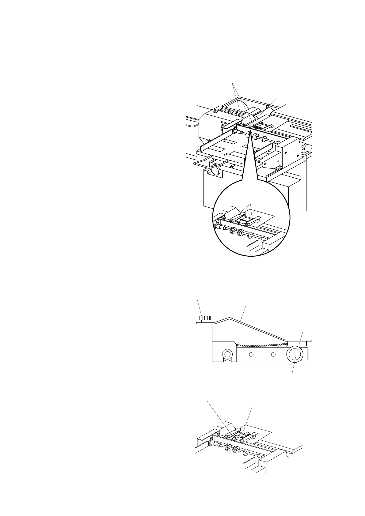
10. Installation of Friction Cover Feeder CF-220
10-2 Set Up
10-2-3 Attachment of Accessories
- To prevent misfeeding of cover caused by
dart on support roller, support roller cleaner
is recommended to use.
- To prevent cover moves back, cover feeding
supporter is recommended to use.
NOTE
Supply a few drops of alcohol on cloth of
support roller cleaner.
1. Loosen fix screws on feed support roller
cleaners and cover feeding supporter.
Fix Screws
Fix Screw
Support Roller
Cleaner
2. Place support roller cleaner so that pad is
placed on roller and the other end is placed
under fix screw. And then fasten fix screw.
3. Attach cover feeding supporter under
middle fix screw and fasten fix screw.
Fix Screw
Middle Fix Screw
Support Roller Cleaner
Pad
Support Roller
Cover Feeding Supporter
86
Page 93

10-2 Set Up
10-2-4 Test Feed of Cover
To confirm proper set up of cover feed unit
and nipping unit, cover test feeding must be
performed.
1. Confirm nipper unit is at lower position.
NOTE
Nipper unit is at lower position when five
screws on nipper unit appear.
2. Depress cover single feed button to feed
a cover to nipper unit.
10. Installation of Friction Cover Feeder CF-220
5 Screws
Cover Single Feed Button
3. Confirm that cover is fed until it touches
cover stopper and feed rollers or two
support rollers slightly touch cover edge.
NOTE
- When support rollers/transport rollers and
cover make noise or support rollers /transport
rollers push cover obviously, slide back cover
feed unit.
- When only one support roller touches, cover
or transport roller is angled against cover,
adjust angle of cover feeder with cover feeder
angle adjust knob.
4. Repeat above step 2 and 3 until cover
can be fed smoothly.
Cover
Stock
Nipper Unit
Cover Feeder
Angle Adjust Knob
87
Page 94

10. Installation of Friction Cover Feeder CF-220
10-3 Installation of CF-220
WARNING
Perform cover feeder unit installation
with two persons.
Left Upper
Screw Hole
Screws
1. Loosen five fix screws.
- Remove upper left screw.
- Loosen other four screws.
2. Attach cover feeder unit.
- Attach cover feeder unit so that cover
feeder table is hung on four screws.
- Install upper left screw and tighten all five
screws firmly.
3.Connect cover feeder cable.
- Connect cover feeder cable to BQ-260
power control box.
4. Fix side screw.
- Open control panel.
- Fix side screw on cover feeder.
2-1-4 Attach Dust Bag
Cover Feeder Table
Side Screw
- Attach dust bag on blower pipe at left side
of BQ-260.
- Fix strings on both small and large openings.
Dust Bag
88
 Loading...