

Horizon BQ-140 User Manual

UM202007-02
011127/BQ140/02E/DV
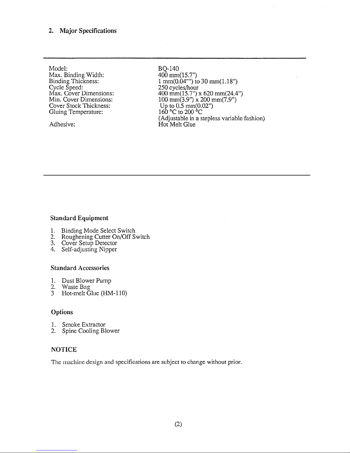
Power Required:
Power Consumption:
Dimentions:
Machine Weight:
120V 60Hz 6.0A
220V 50Hz 5.8A
220V 60Hz 4.3A
240V 50Hz 5.8A
950W/50Hz, 1050W/60Hz
1,450(W) x 525(D) x 1,040(H) [57.1" x 20.7" x 41.0"]
203 kgs (448 lb)

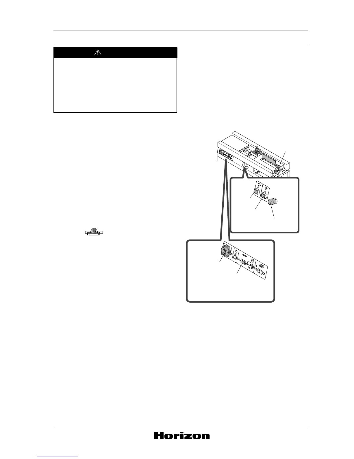
WARNING
- Turning on the power switch starts to
heat the glue tank which will finally
reach a temperature of around 180
degrees Celsius. Keep your hands and
fingers away from the glue tank, otherwise severe personal injury can result.
First, the clamper is needed to move to
the left end to perform the following
procedures.
1.
Turn on the power switch and wait for the
start lamp to light which shows that the
hot-melt glue is ready for binding.
NOTE
It takes about 20 minutes to heat the hotmelt when the BQ-140 was OFF, and about 7
minutes when the BQ-140 was in standby
mode.
2. Select with the binding mode
selector switch.
3. Insert the book block 0.04" (1 mm) into
the clamper so that the book block is
lifted about 0.2" (5 mm) from the nipper.
- The glue is not be applied on the spine.
4. Close the clamper by turning the clamp
handwheel clockwise.
5. Press the start button.
- The clamper moves to the left and stops at
the left end.
6. Press the stop button.
Cover Stopper Installation Instruction
Binding Mode
Selector Switch
Start
Button
Reset Button
Clamp
Handwheel
Stop Button
Power Switch
[Book Binder BQ-140]
UM202028-00
000905/BQ140/HN/HS/HN
(Page 1)
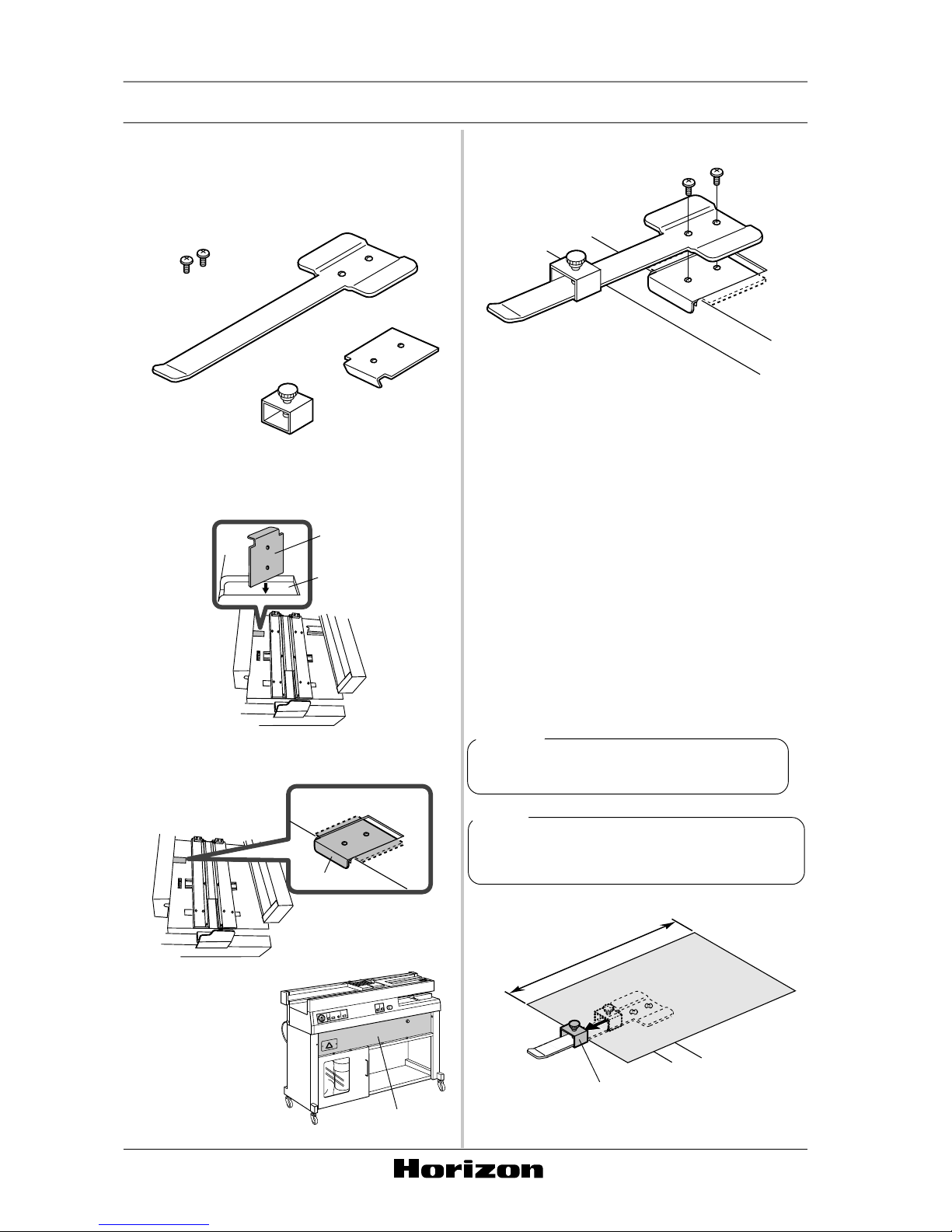
7. Install the cover stopper by performing
the following procedures.
1) Check the parts of cover stopper.
2) Insert the bracket into the hole for installation of cover stopper.
3) Hold the bracket as shown in the following drawing.
Bracket
Stopper
Fixing
Screws
(4 mm)
Cover Guide
20.25" (514 mm)
at maximum
Front Cover
Stopper
Cover Stopper Installation Instruction
Bracket
Hole
Bracket
Attention
When you dropped
the bracket off into
the hole, remove the
front cover (6 fixing
screws) to pick up the
bracket.
4) Attach the cover guide to the bracket with
2 fixing screws.
- Installation for the cover stopper is completed.
8. Pull up the stop button.
9. Press the reset button.
- The clamper moves to the right and stops
at the home position (above the nipper).
10. Open the clamper by turning the clamp
handwheel counterclockwise.
11. Remove the book block by sliding it out
to the right.
Attention
When using this cover stopper, the cover
length is 20.25 " (514 mm) at maximum.
Point
Adjust the stopper according to the cover
length.
[Book Binder BQ-140]
(Page 2)

PARTS BOOK
BQ-140/BQ-51
Perfect Bookbinding Machine
Vol.2
UB702004-07
061107/BQ140/07/MO

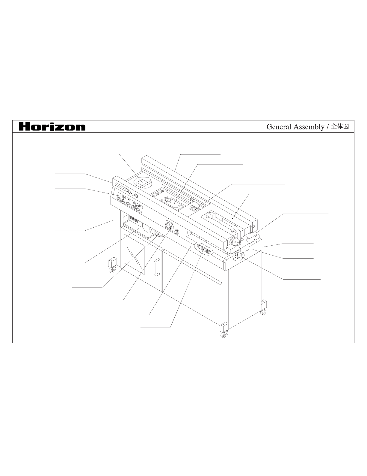
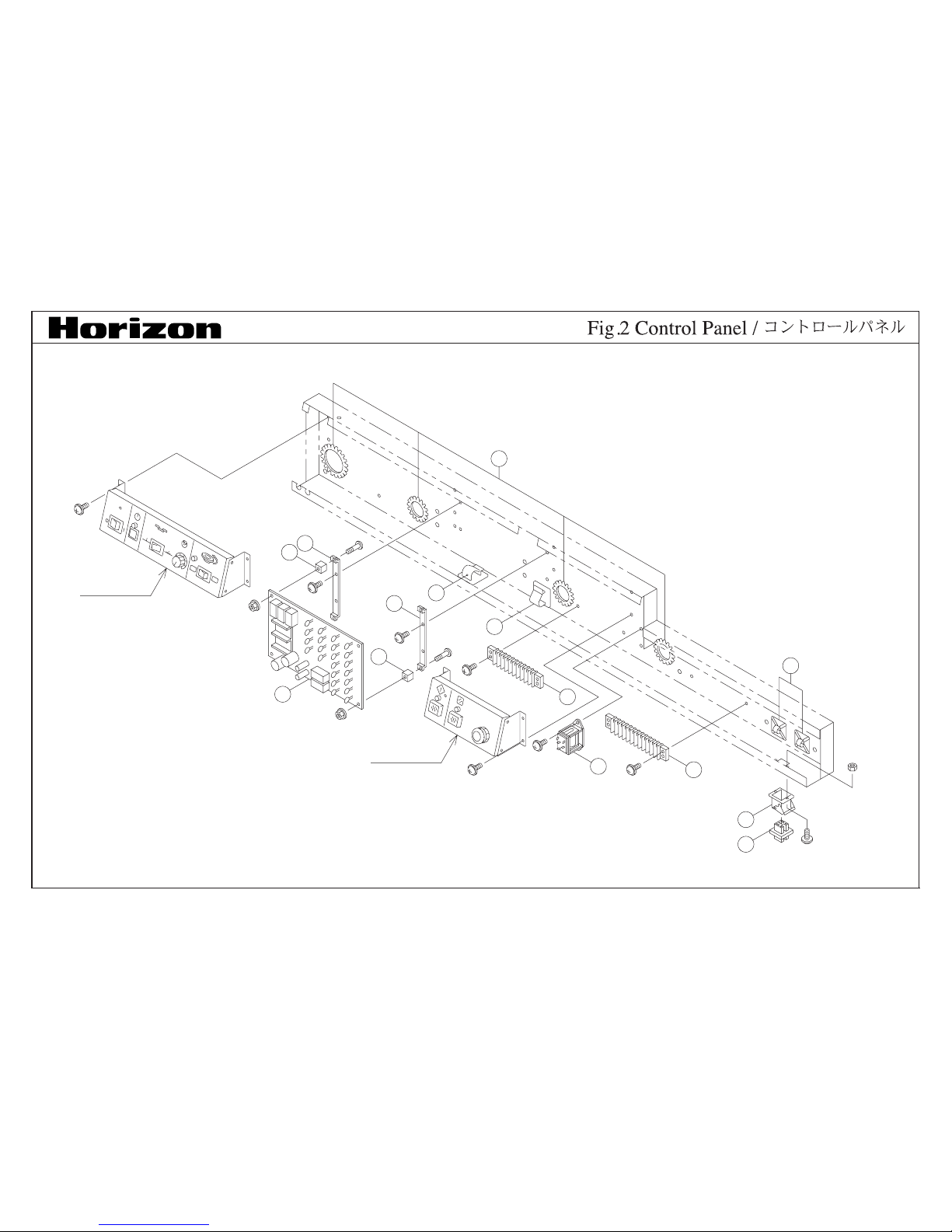
See Fig.2
See Fig.27,33
See Fig.5,7,32
See Fig.22,23,24
See Fig.18,19,20,21
See Fig.8,9,10
See Fig.12,13,15
See Fig.11
See Fig.25
See Fig.16,17
See Fig.6
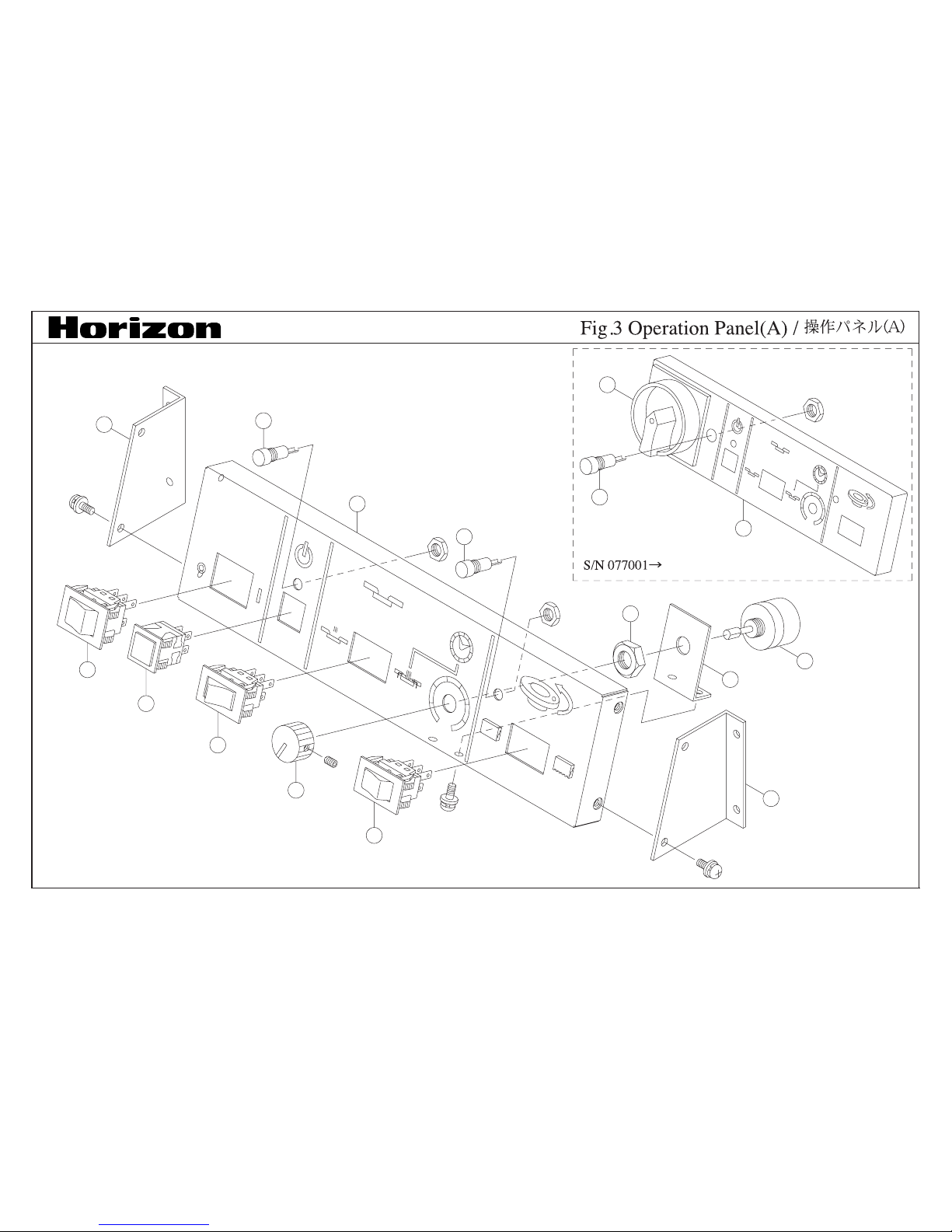
See Fig.3
See Fig.26
See Fig.30
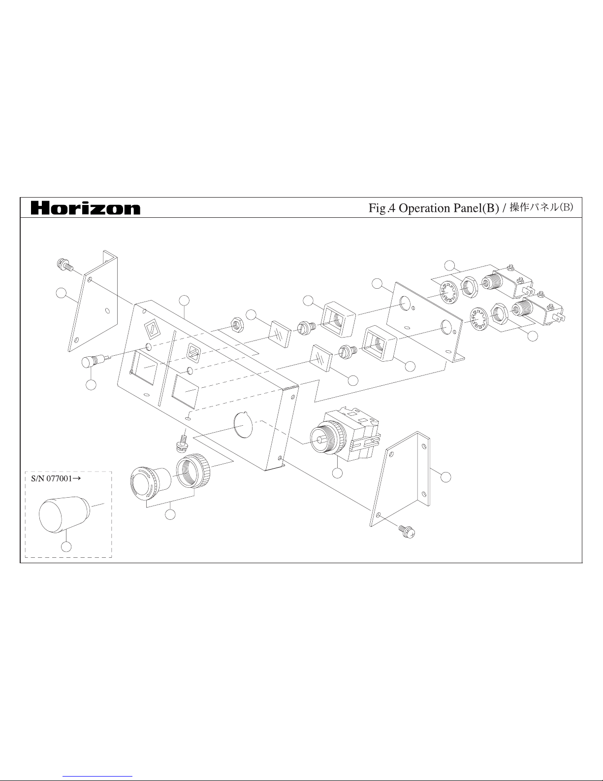
See Fig.4
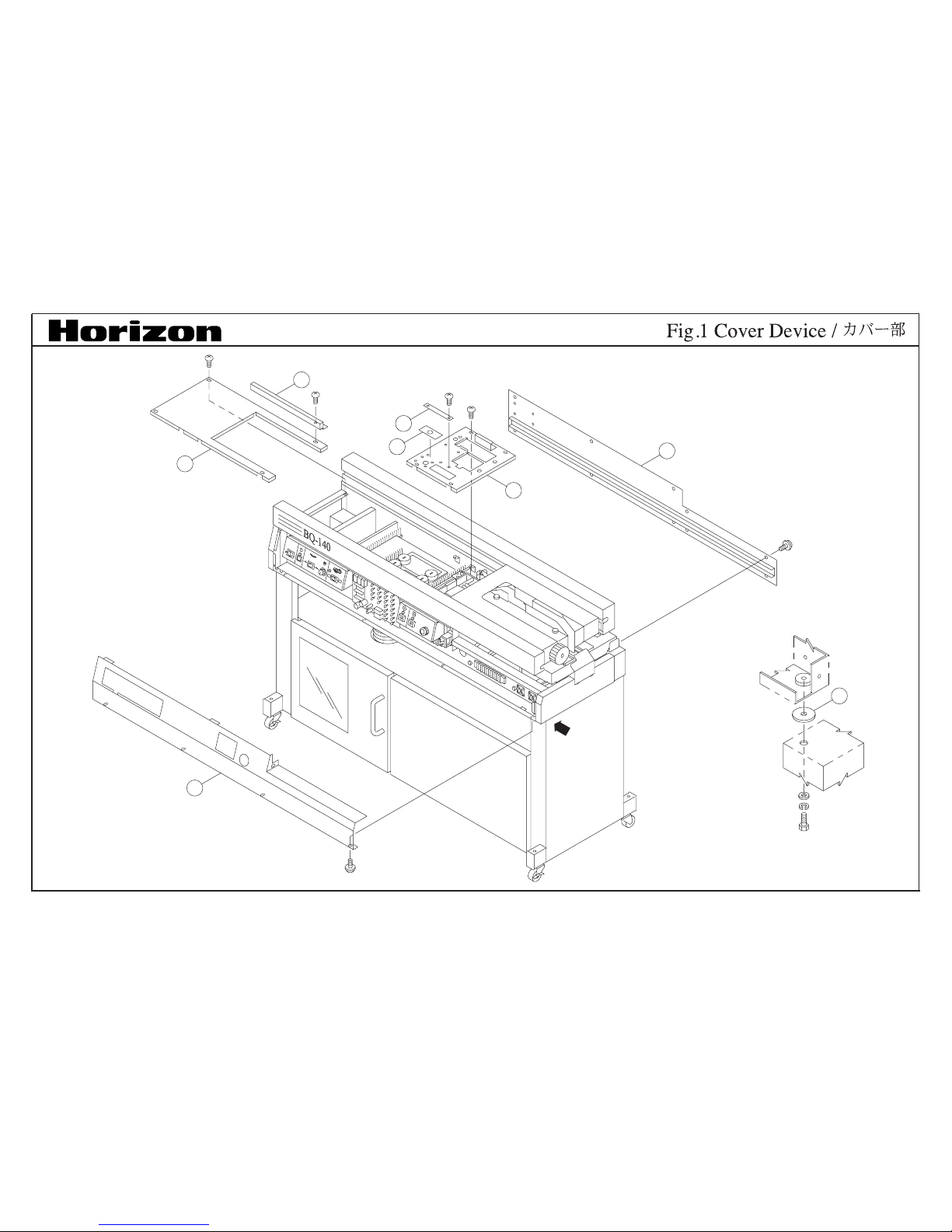
See Fig.1
See Fig.34
BQ-140/51

A
DETAIL A
6
5
1
7
3
8
4
2
BQ-140/51

BQ-140/BQ-51
INDEX Parts No. Qt
y
S/N From ToDescription Price Remarks
Fig.
1
1 M013548-02 1 COVER
2 M013542-00 1 REAR COVER
3 4000286-00 1 CAUTION PLATE
4 M013549-00 1 MELT TANK COVER
5 M013545-00 1 FRONT COVER
6 M013612-00 3 SPACER
7 M013626-01 1 COVER
8 4003143-01 1 LABEL
See Fig.3
See Fig.4
6
7
6
7
4
3
11
8
9
10
5
5
1
2
BQ-140/51

BQ-140/BQ-51
INDEX Parts No. Qt
y
S/N From ToDescription Price Remarks
Fig.
2
1 4003188-00 4 BUSH
2 4004220-00 2 BASE
3 4001557-00 1 TERMINAL BOARD
4 4002046-00 1 076899 TERMINAL BOARD
4 X01 1 077001 TERMINAL
5 4001736-00 2 CLAMP
6 M013559-00 2 BRACKET
7 M001790-06 2 SPACER
8 QPW-274 1 P.C.B.
9 4021323-00 1 077001 CONNECTOR COVER
10 A930528-01 1 077001 CONNECTOR
11 4012523-00 1 095001 CONTROLLER 100V/115V
11 4012542-00 1 095001 CONTROLLER 230V
4
5
4
3
2
6
7
6
10
1
8
9
8
2
11
7
BQ-140/51

BQ-140/BQ-51
INDEX Parts No. Qt
y
S/N From ToDescription Price Remarks
Fig.
3
1 M013564-00 1 BRACKET
2 4003235-00 1 076899 SWITCH 100/120V
2 4003242-00 1 076899 SWITCH 220/240V
2 4008830-00 1 077001 POWER SWITCH
3 4003197-00 1 SWITCH
4 4003236-00 2 SWITCH
5 M001754-03 1 KNOB
6 4001302-00 2 076899 LAMP(RED)
6 4001304-00 2 077001 098899 LAMP(YELLOW)
6 4012868-00 2 099001 LAMP
7 M013560-01 1 076899 PANEL(A)
7 M013560-04 1 077001 OPERATION PANEL(A)
8 4003202-00 1 VOLUME
9 M013561-00 1 BRACKET
10 M013565-00 1 BRACKET
11 4006389-00 1 077001 LAMP
1
2
4
10
9
6
8
5
9
7
8
3
3
3
BQ-140/51

BQ-140/BQ-51
INDEX Parts No. Qt
y
S/N From ToDescription Price Remarks
Fig.
4
1 M013564-00 1 BRACKET
2 4001302-00 1 076899 LAMP(RED)
2 4001304-00 1 077001 098899 LAMP(YELLOW)
2 4012868-00 1 099001 LAMP
3 4003205-00 1 076899 STOP BUTTON
3 4007224-01 1 077001 STOP SWITCH
4 M013562-01 1 076899 PANEL(B)
4 M013562-05 1 077001 OPERATION PANEL(B)
5 4001503-00 1 SWITCH(BLUE)
6 4001754-00 1 SWITCH(BLACK)
7 M013563-02 1 PLATE
8 4001500-00 2 SWITCH
9 M001975-04 2 FRAME
10 M013565-00 1 BRACKET
C
DETAIL A
DETAIL D
DETAIL B
DETAIL C
A
B
D
17
15
14
3
4
12
13
9
8
6
5
7
6
8
6
10
7
6
16
2
11
18
BQ-140/51
1

BQ-140/BQ-51
INDEX Parts No. Qt
y
S/N From ToDescription Price Remarks
Fig.
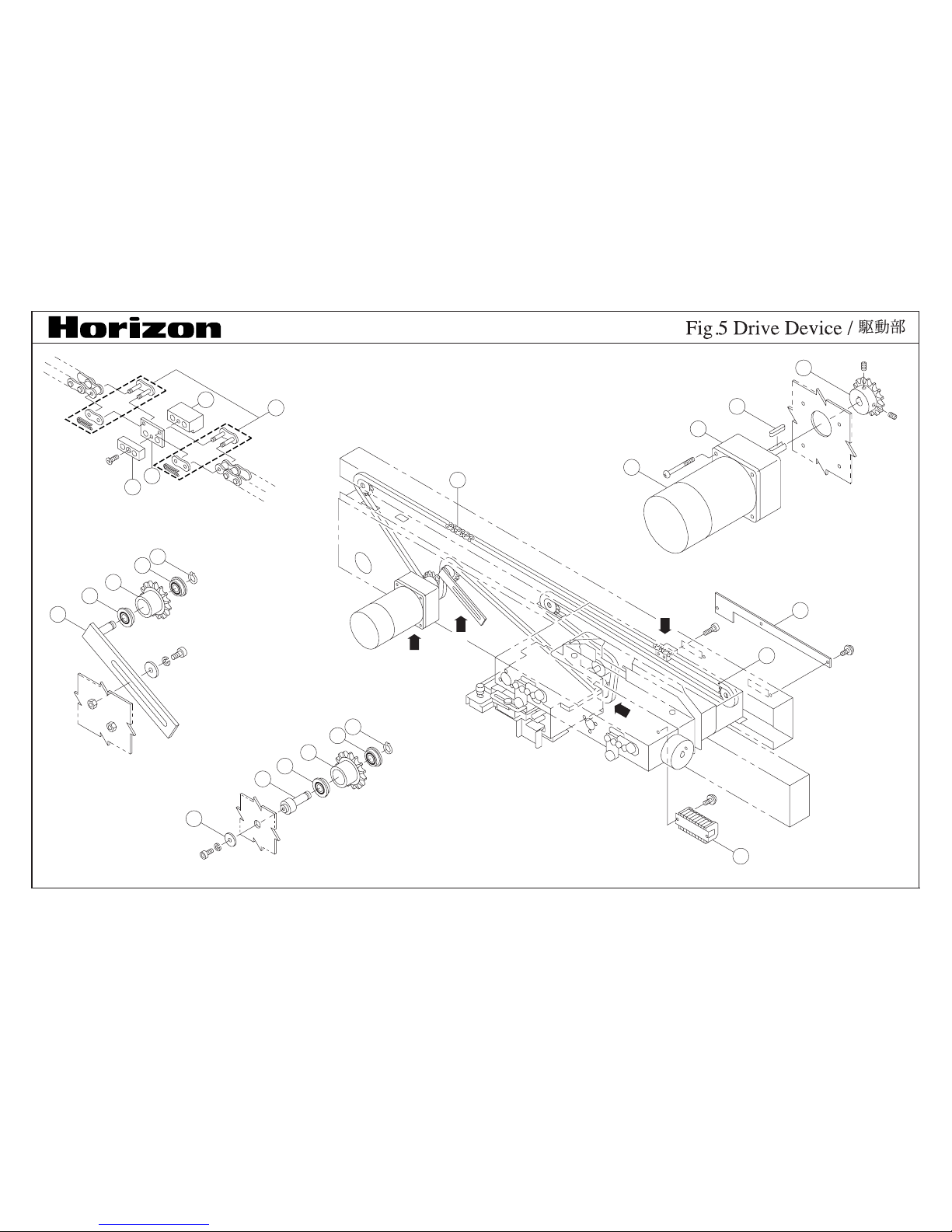
5
1 4003193-00 1 CHAIN
2 M013616-02 1 COVER
3 A930501-00 1 MOTOR
4 M013606-01 1 SPROCKET 50Hz
4 M013607-01 1 SPROCKET 60Hz
5 M013609-00 1 BRACKET
6 4003178-00 2 BEARING
7 M013526-00 4 SPROCKET
8 STW-8 1 SNAP RING
9 M013525-01 4 SPACER
10 M013519-02 1 SHAFT
11 M013667-01 1 BLOCK
12 M013645-01 1 PLATE
13 M013681-01 1 BLOCK
14 4003186-00 1 GEAR HEAD
15 4008521-00 1 KEY
16 4003192-00 1 CHAIN
17 4008962-00 1 TERMINAL BOARD
18 4001739-00 2 JOINT
 Loading...