

Horizon AVALON II Owner’s Manual
0 _k I ZO
÷ 4,
ITNES
AVALON II EXERCISE BIKE
J
f
O _, I ZO
f
U N P A C K I N G
Unpack your Exercise Bike where you will be
using it. Place your bike on a level flat surface.
It is recommended that you place a protective
covering on your floor. You will only need to
attach the following items. Verify that the
following parts and tools are included:
Parts
• 1 Rear Foot Tube
• 1 Handlebar Set
• 1 Seat Rail
• 1 Seat Back
• 1 Seat Bottom
• 1 Seat Frame
• 1 Console Mast
• 1 Console Mast Boot
• 2 Mobile Wheels
• 1 Console
• 2 AA Batteries
• 2 Pedals
• 2 Wheel Sleeves
• 1 Tension Knob
• 1 Hardware Pack (contents listed below)
Tools (included)
• 5mm Allen Wrench/
Phillips Screw Driver
• Flat Wrench
H a r d w a r e (ActualSize)
Attach the Foot Wheels
a. Insert the wheel sleeves on each
side of the front wheel tube.
b. Align the holes in the wheel sleeves
with the holes in the wheel tube.
Insert two 12mm screws (A) and
secure with a screwdriver.
c. Attach the mobile wheels to the
wheel sleeves. Insert two 14mm
washers (F) and two 20mm bolts
(G) and secure with a screwdriver.
f
Attach the Rear Foot
a. Align the holes of the rear foot
tube with the holes on the seat
rail.
b. Insert two 20mm bolts (B) and
secure with a 5mm allen wrench.
f
ITNE_
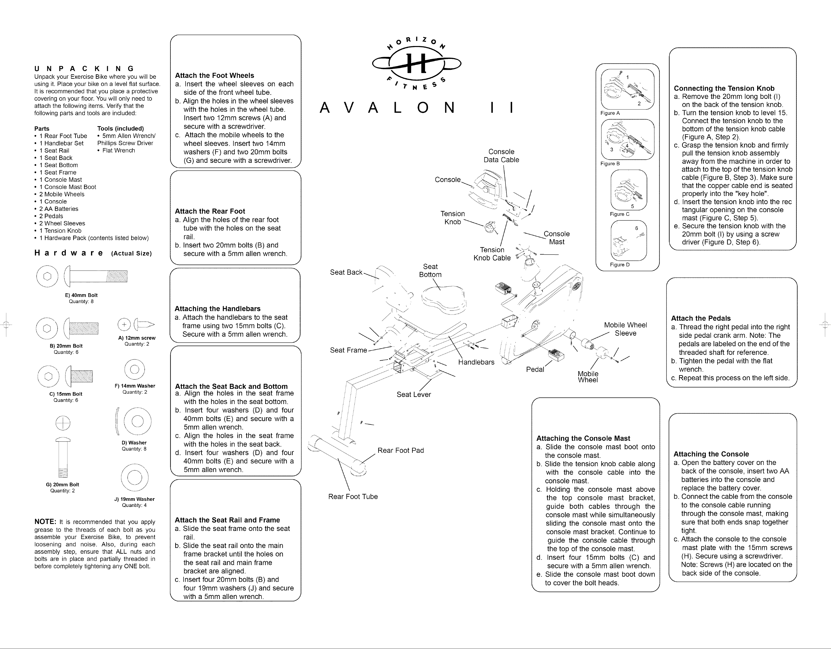
Connecting the Tension Knob
a. Remove the 20mm long bolt (I)
on the back of the tension knob.
A V A L O N I I
Figure A
J
Figure B
K"
5 j
Figure C
b. Turn the tension knob to level 15.
Connect the tension knob to the
bottom of the tension knob cable
(Figure A, Step 2).
c. Grasp the tension knob and firmly
pull the tension knob assembly
away from the machine in order to
attach to the top of the tension knob
cable (Figure B, Step 3). Make sure
that the copper cable end is seated
properly into the "key hole".
d. Insert the tension knob into the rec
tangular opening on the console
mast (Figure C, Step 5).
e. Secure the tension knob with the
20mm bolt (I) by using a screw
driver (Figure D, Step 6).
J
©
B) 20mm Bolt
©
C) 15mm Bolt
E) 40mm Bolt
Quantity: 8
Quanttty: 6
Quanttty: 6
A) 12mm screw
Quantity: 2
©
F) 14mm Washer
Quantity: 2
f
Attaching the Handlebars
a. Attach the handlebars to the seat
frame using two 15mm bolts (C).
Secure with a 5mm allen wrench.
f
Attach the Seat Back and Bottom
a. Align the holes in the seat frame
with the holes in the seat bottom.
J
Figure D
J
/-
Attach the Pedals
Mobile Wheel
Sleeve
J
a. Thread the right pedal into the right
side pedal crank arm. Note: The
pedals are labeled on the end of the
\
Handlebars
Pedal
threaded shaft for reference.
b. Tighten the pedal with the flat
wrench.
Mobile
Wheel
c. Repeat this process on the left side.
Seat Lever
/-
D) Washer
Quanttty: 8
,/
c I
G) 20mm Bolt '\/
Quantity: 2
J) 19mm Washer
Quantity: 4
NOTE: It is recommended that you apply
grease to the threads of each bolt as you
assemble your Exercise Bike, to prevent
loosening and noise. Also, during each
assembly step, ensure that ALL nuts and
bolts are in place and partially threaded in
before completely tightening any ONE bolt.
I
b. Insert four washers (D) and four
40mm bolts (E) and secure with a
5mm allen wrench.
c. Align the holes in the seat frame
with the holes in the seat back.
d. Insert four washers (D) and four
40mm bolts (E) and secure with a
5mm allen wrench.
f
Attach the Seat Rail and Frame
a. Slide the seat frame onto the seat
rail.
b. Slide the seat rail onto the main
frame bracket until the holes on
the seat rail and main frame
bracket are aligned.
c. Insert four 20mm bolts (B) and
four 19mm washers (J) and secure
with a 5mm allen wrench.
f
Attaching the Console Mast
Rear Foot Pad
J
Rear Foot Tube
a. Slide the console mast boot onto
the console mast.
b. Slide the tension knob cable along
with the console cable into the
console mast.
c. Holding the console mast above
the top console mast bracket,
guide both cables through the
console mast while simultaneously
sliding the console mast onto the
console mast bracket. Continue to
guide the console cable through
the top of the console mast.
d. Insert four 15mm bolts (C) and
secure with a 5mm allen wrench.
e. Slide the console mast boot down
to cover the bolt heads.
Attaching the Console
a. Open the battery cover on the
back of the console, insert two AA
batteries into the console and
replace the battery cover.
b. Connect the cable from the console
to the console cable running
through the console mast, making
sure that both ends snap together
tight.
c. Attach the console to the console
mast plate with the 15mm screws
(H). Secure using a screwdriver.
Note: Screws (H) are located on the
back side of the console.
J
 Loading...