

Page 1

A
PC-61 Revision Control List
x
1-9,1-10,1-11,2
Manual No. Date Bulletin Code S/N applied History
US504004-00 Jan/17/2001 (First Edition)
1.Correcting the description of "2-11 Hydraulic Pressure Does not Operate." 2-20
2.Correcting the Hydraulic Circuit to (For S/N 100001 to 122899) and (For S/N
123001 or above). 5-3.4
US504004-01 Jun/4/2001 1.Adding precautions on P.C.board and ROM IV
2.Adding the relay in the control bo
3.Correcting producers No. for the rlay 7-8
4.Correcting wiring diagrams 7-6, 7-10, 7-11
US504004-03 Feb/27/2008 1. Adding the 61II-related pages.
2. Correcting the term "cut knife" to the "cutting knife".
3. Correcting the term "back gauge" to the "backgauge".
Page
6-4
23,2-24,2-25,226,2-27,2-28,316,3-17,6-5,6-6,67,6-8,6-9,7-14,715,7-16,7-17,718,7-19
All Page
All Page
Page 2

Page 3

FOREWORD
Paper Cutter
Model APC-61
Important Information
This service manual is designed to help you to repair and maintain the APC-61 in order to keep it in good operating condition.
Please read and understand the instructions in this service manual before performing any repair or maintenance.
- Horizon International Inc. shall not be liable for incidental or consequential damages resulting from: improper or inadequate
maintenance by the customer; unauthorized modification or misuse; or operation outside of the environmental specifications
for the product.
- Horizon International Inc. follows a policy of continuing improvement in design and performance of the product. Therefore,
the product design and specifications are subject to change without prior notice and without our legal obligation.
- All rights are reserved. No part of the manual may be photocopied, reproduced or translated to another language without the
prior written consent of Horizon International Inc.
US504004-03080131/APC61/03E/KY/NT/P6/I9/P7
1
Page 4

Safety Precautions
- Please read and understand all safety instructions which include the terms WARNING, and CAUTION. If these safety instruc-
tions are ignored, personal injury may result.
- The repair, maintenance and safety instructions in this manual are valid only when the repair or maintenance work is performed
according to the procedures described in this manual.
- The term WARNING indicates a potentially hazardous situation which, if not avoided, could result in death or serious injury.
- The term CAUTION indicates a potentially hazardous situation which, if not avoided, may result in damage on machines. It may
also be used to alert against unsafe practices.
- Horizon International Inc. cannot anticipate every possible situation that might involve a potential hazard. The instructions in this
manual and the warning labels on the machine are therefore not all-inclusive.
- All equipment shall be locked out or tagged out to protect against accidental or inadvertent operation when such operation, repair
or maintenance could cause injury to personnel. Do not attempt to operate any switch, valve, or any electrical device when it has
been locked or tagged out.
- Some of the drawings in this manual show the machine uncovered for explanations of the details inside the machine.
2
Page 5
I. Necessary Tools for Maintenance and Repair
9
n
n
n
K
e
y
n
n
a
y
)
.C
B
.
b
alue
ef
e
f
otal Counts Setting
e
CA
UTION
umeric
e
umbers
par
n
g
Use the following tools for maintenance and repair.
1. Screw Driver No. 2
2. Screw Driver 6 to 7 mm
3. Allen Wrenches 1.5, 2, 2.5, 3, 4, 5, and 6 mm
4. Open-ended Wrench 5.5 x 7, 8 x 10, 13 x 17 mm
5. Box Wrench 5.5 mm
6. Snap-ring Expander
II. Abbreviations in This Manual
2. The following abbreviation represent electronic and electrical parts.
Abbreviation
Meaning
CL Clutch
BK Brake
SW Switch
PS Proximity Switch
mSW Micro-switch
M Motor
1. The following abbreviations represent wire colors.
Abbreviation
Color
Abbreviations
Color
BRN Brown PNK Pink
RED Red LBL Light Blue
ORN Orange YEG Yellow Green
YEL Yellow YEO Yellow Orange
GRN Green LYE Light Yellow
BLU Blue GND Ground
VIO Violet
GRY Gray
WHT White
BLK Black
LED Light Emitting Diode
VR Potentiometer
RY Relay
AS Assembly
1-5 Entering Service Scree
"Numeric
"Normal Cutting" Scree
"Maintenance" Scree
"ormation" Scree
pad" Scree
se
our digits
utton is pressed,the
1-
.
"Service" Scree
Moter Home Position Displ
R
r to 1-7
iz
OK]
.
means
a page that is
related to
APC-61II.
will
3
Page 6

Contents
FOREWORD........................................................................... 1
Paper Cutter ............................................................................ 1
Model APC-61 ......................................................................... 1
Important Information ........................................................... 1
I. Necessary Tools for Maintenance and Repair .................. 3
II. Abbreviations in This Manual .......................................... 3
1. Machine Parts Descriptions
1-1 General View ..................................................................... 1-2
1-2 Operation Panel Descriptions (T61)................................ 1-5
1-3 Operation Panel Descriptions (M61) .............................. 1-7
1-4 Cover Descriptions............................................................ 1-8
1-5 Entering Service Screen (61II)......................................... 1-9
1-6 Calibration of Home position (61II)................................ 1-10
1-7 Checking Motor Home Position Distance (61II)............ 1-11
2. Troubleshooting
2-1 blinks on the Display (Backgauge Does Not Operate)
Part 1 ................................................................................. 2-2
Part 2 ................................................................................. 2-3
Part 3 ................................................................................. 2-4
Part 4 ................................................................................. 2-5
2-2 Cut Size is Not Equal
Part 1 ................................................................................. 2-6
Part 2 ................................................................................. 2-7
2-3 Knife Does Not Lower (Clamp Does Not Lower Either)
Part 1 ................................................................................. 2-8
Part 2 ................................................................................. 2-9
Part 3 ................................................................................. 2-10
2-4 Knife Does Not Lift
Part 1 ................................................................................. 2-11
Part 2 ................................................................................. 2-12
2-5 Clamp Lowers but Knife Does Not Lower ..................... 2-13
2-6 Clamp Does Not Lower Though Foot Pedal
Is Stepped On................... 2-14
2-7 Backgauge Does Not Operate
Part 1 ................................................................................. 2-15
Part 2 ................................................................................. 2-16
2-8 Backgauge Does Not come Forward
(But goes backward) .......... 2-17
2-9 Backgauge Operates By Itself.......................................... 2-18
2-10 Nothing Is Shown on Displays ....................................... 2-19
2-11 Hydraulic Pressure Does Not Operate.......................... 2-20
2-12 Knife Is Down before Operation ................................... 2-21
2-13 Knife Lower Limit Position Varies ............................... 2-22
2-14 Backgauge Does Not Move (61II) ................................. 2-23
2-15 Error Code (61II)............................................................ 2-24
4
Page 7

3.Adjustment
3-1 Fine Adjustment of Cut Size
(Different is about 0.1 mm) ................. 3-2
3-2 Adjustment of Cut Size
(Different is about between 0.1 and 0.2 mm)................. 3-3
3-3 Rough Adjustment of Cut Size
(Different is about 0.5 mm) ................. 3-4
3-4 Adjustment of Electromagnetic Brake Gap................... 3-5
3-5 Adjustment of Electromagnetic Clutch Gap .................. 3-6
3-6 Adjustment of Knife Replacement Position ................... 3-7
3-7 Adjustment of Knife Lower Limit Position.................... 3-8
3-8 Adjustment of Cutting Line Width ................................. 3-9
3-9 Release of Locked Knife................................................... 3-10
3-10 Pressure Adjustment of Hydraulic Pump .................... 3-12
3-11 Right Angle Adjustment of Backgauge to the Table....... 3-13
3-12 Horizontal Adjustment of Backgauge to the Table ..... 3-14
3-13 Parallel Adjustment of Backgauge to the Knife .......... 3-15
3-14 Backgauge Drive Section Mechanism (61II) ............... 3-16
3-15 Spindle Section Mechanism (61II)................................ 3-17
4.Repair
4-1 Replacing Knife Holder.................................................... 4-2
4-2 Replacing Clamp............................................................... 4-5
4-3 Replacing Backgauge........................................................ 4-8
4-4 Replacing Backgauge Block............................................. 4-9
4-5 Replacing Knife Link A and B......................................... 4-10
4-6 Replacing Clamp Link A and B....................................... 4-11
4-7 Replacing Joint (For Clamp) ........................................... 4-13
4-8 Replacing Joint (For Knife) ............................................. 4-14
4-9 Replacing Rod End ........................................................... 4-16
4-10 Replacing Rod ................................................................. 4-17
4-11 Replacing Encoder .......................................................... 4-18
4-12 Replacing Electromagnetic Brake................................. 4-19
4-13 Replacing Electromagnetic Clutch................................ 4-20
4-14 Replacing Belt (For High Speed)................................... 4-21
4-15 Replacing Belt (For Low Speed).................................... 4-22
4-16 Replacing Motor (For High Speed)............................... 4-23
4-17 Replacing VC Relay and Contactor .............................. 4-24
4-18 Replacing Sensors (Detecting Knife Replacement
Position, Knife Lower Limit Position) ..... 4-25
4-19 Replacing Power Supply ................................................ 4-26
4-20 Replacing Operation Panel ............................................ 4-27
4-21 Replacing Control Board ............................................... 4-28
4-22 Replacing Fuse and Resetting Thermal Relay ............. 4-29
4-23 Replacing Limit Switches............................................... 4-30
4-24 Replacing Knife Holder Upper Limit Position Sensor 4-31
4-25 Replacing Limit Switch
for Clamp Upper Limit Position.................. 4-32
4-26 Replacing Cutting Line Bulb ......................................... 4-33
4-27 Replacing Electromagnetic Valve.................................. 4-34
5
Page 8

5.Hydraulic Parts
5-1 Hydraulic Parts Description
(For S/N 100001 or above) ............................................... 5-2
5-2 Hydraulic Circuit .............................................................. 5-3
(For S/N 100001 to 122899) .............................................. 5-3
(For S/N 123001 or above) ................................................ 5-4
5-3 Hydraulic Parts Descriptions
(For S/N 099999 or below) ................................................ 5-5
5-4 Hydraulic Circuit (For S/N No.099999 or below) .......... 5-6
6. Electrical Parts Description
6-1 Identification and Location of Motors and Encoder ..... 6-2
6-2 Identification and Location of Sensors and Switches .... 6-3
6-3 Identification and Location
of Components in the Control Box .... 6-4
6-4 Location and Name of Pairs in Control Box(61II) ........ 6-5
6-5 Panel Internal Layout and Name (61II) ......................... 6-6
6-6
Hydraulic Pressure and Motor Unit Layout and Name (61II) ..
6-7 Backgauge Motor Section Layout and Name (61II) ...... 6-8
6-8 Parameter Settings of Amplifier
for Servo Motor (61II) ........................ 6-9
6-7
7-4 Control Board (QPW-153D), LED and Main Parts ...... 7-5
7-5 Control Board (QPW-153D) Connector Layout ............ 7-6
7-6 Foot Switch Control Board (QPW-155A) ...................... 7-7
7-7 Foot Switch Control Board (QPW-155A) ...................... 7-8
7-8 Control Box Schematic Diagram ..................................... 7-9
7-9 Wiring Diagram ................................................................ 7-10
7-10 Terminal-1 ....................................................................... 7-11
7-11 Terminal-2 Wiring Diagram (Inside of Control Box) . 7-12
7-12
LED and DSW of Control P.C.B. P083411(QPM-195) (61II) ....
7-13
LED and DSW of Panel P.C.B. P071811(QPM-157) (61II)..
7-14 P083411(QPM-195) Connector Connection (61II) ...... 7-16
7-15 New Circuit (Power System) (61II) ............................... 7-18
7-16 Safety Circuit Performance (61II) ................................ 7-19
7-14
7-15
7. System Wiring and Connections
7-1 Board Connections ............................................................ 7-2
7-2 CPU Board (QPW-162) .................................................... 7-3
7-3 Display Board M61:QPW-175, T61:QPW-176 .............. 7-4
6
Page 9

1.Machine Parts Descriptions
1-1 Machine Parts Descriptions ........................................................................... 1-2
1-2 Operation Panel Descriptions (T61) ..............................................................1-5
1-3 Operation Panel Descriptions (M61) .............................................................1-7
1-4 Cover Descriptions ..........................................................................................1-8
1-5 Entering Service Screen (61II) .......................................................................1-9
1-6 Calibration of Home Position (61II) ............................................................1-10
1-7 Checking Motor Home Position Distance (61II) ........................................ 1-11
1-1
Page 10
APC-T61
HYDRULIC CUTTER
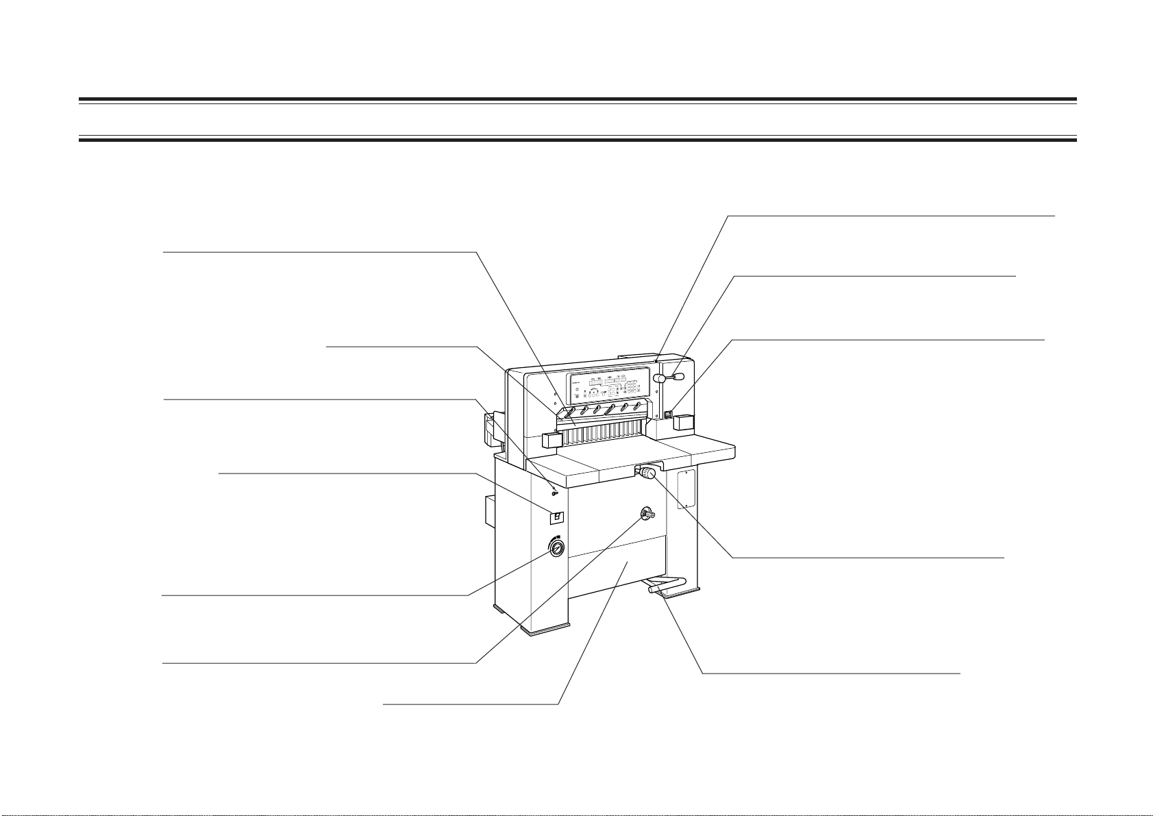
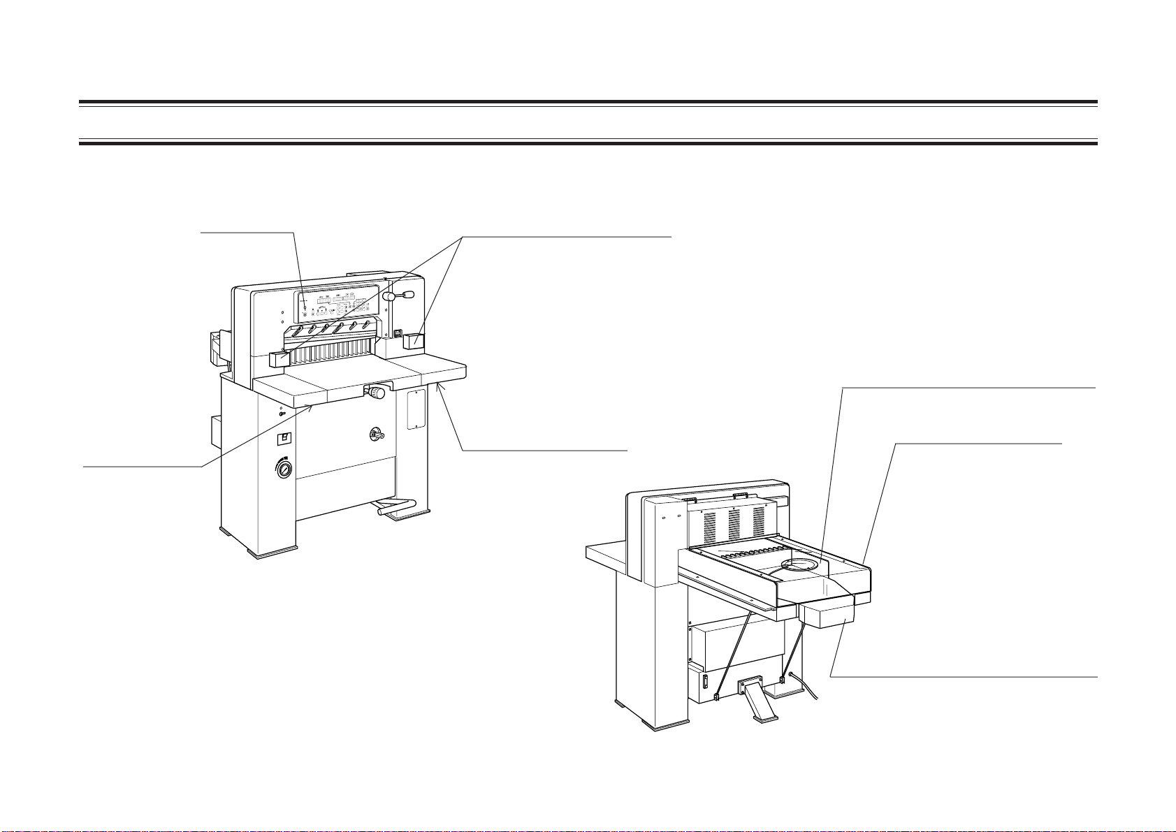
1-1 General View
Clamp
This clamp holds sheets not to move the sheets
when they are cut.
(500 to 1,700kg/cm )
Knife Angle Adjust Lever Fix Screw
Knife angle adjust lever is fixed with this screw.
Knife Angle Adjust Lever
2
The knife angle adjusted with this lever.
Cutting Knife
Cutting Depth Adjust Dial
This dial is used to adjust the knife lower limit
position only when Knife Operation Mode
Select Switch is turned off.
Cutting Knife ON/OFF Switch and Lamp
?
?
APC-T61
HYDRULIC CUTTER
7 8 9
4 5 6
1 2 3
-
P
+
P
.
E
c
0
-
S
+
S
When this switch is turned up, only clamping
will be performed with lamp lighting.
Power Switch
The type of this switch is the breaker.
Backgauge Adjust Knob
This knob is used to adjust backgauge.
Paper Clamp Pressure Indicator
Paper Clamp Pressure Adjusting Knob
Foot Pedal
This pedal is used to lower clamp.
Oil Tank
It can contain 40 liter of oil.
1-2
Page 11
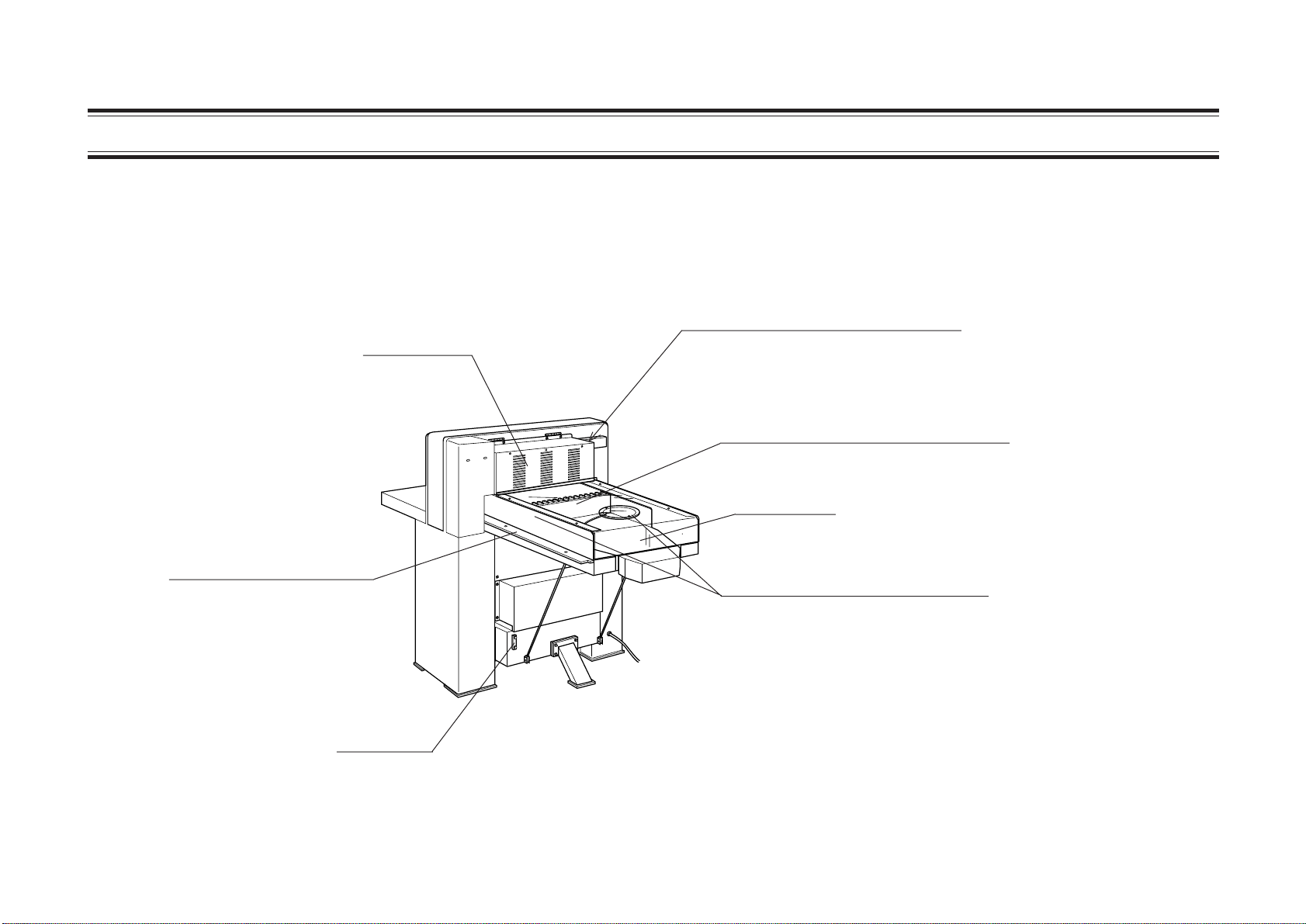
1-1 General View
Pressure Support Plate
Control Box
Light Switch
When turning up the lever, the table is
lightened up, but it becomes difficult to
see the cut line.
Backgauge
This backgauge is the back stop of
sheets to be cut.
Back Table
Side Guides
These guides are register plates for
preparing the sheets right angle
against cutting knife.
Oil Gauge
1-3
Page 12
APC-T61
HYDRULIC CUTTER
1-1 General View
Cutting Button A
Key Switch
Photoelectric Guard
When there is a foreign object
on the optical line between
?
?
APC-T61
HYDRULIC CUTTER
7 8 9
4 5 6
1 2 3
-
P
+
P
.
E
c
0
-
S
+
S
photoelectric guards, the ray is
blocked and safety function
operates. Therefore, knife and
clamp does not lower.
Oil Feed Cover For Backgauge
Backgauge Cover
Cutting Button B
This button and cutter A
button must be pressed
simultaneously to start
to cutting operation.
1-4
Motor encoder Section
The high speed motor, low speed motor,
electromagnetic clutch, brake and encoder are housed.
Page 13
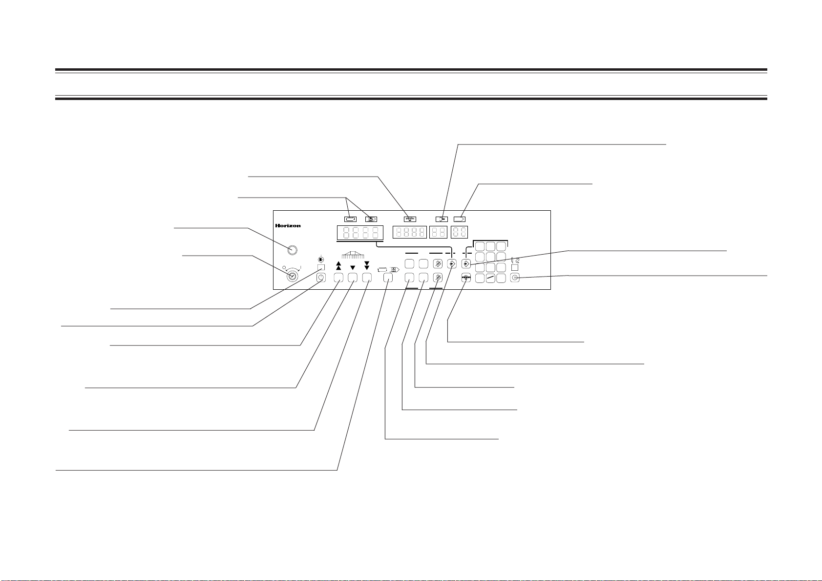
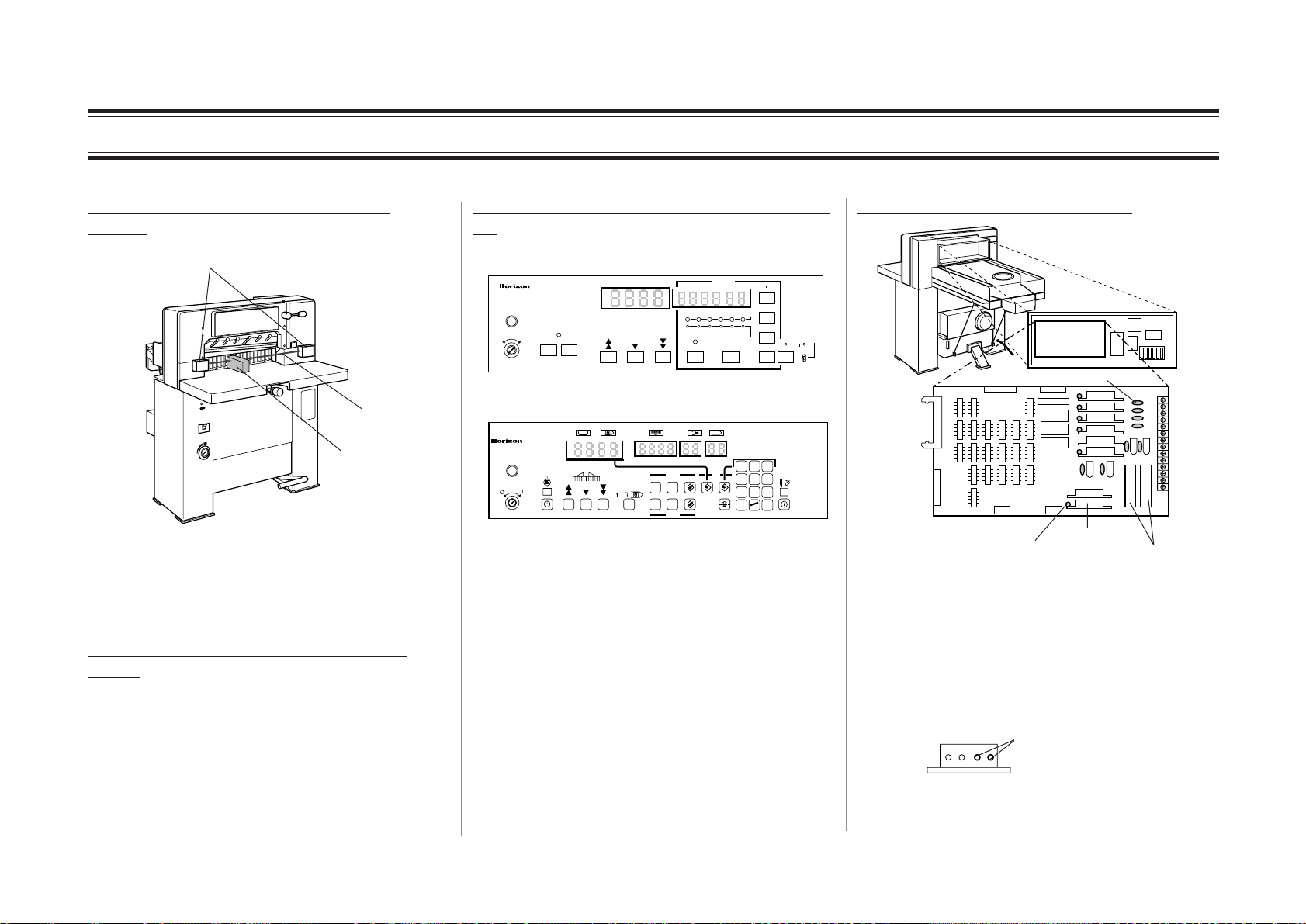
1-2 Operation Panel Descriptions (T61)
APC-T61
HYDRULIC CUTTER
Full Memory Lamp
This lamp lights when input memory is full.
Push-out Memory Lamp
Repeat/Setup Lamp
Power Lamp
HYDRULIC CUTTER
Key Switch
Hydraulic Pressure Lamp
Hydraulic Pressure ON/OFF Switch
High Speed Backward Button
This button is used to move backgauge
backward at high speed.
Low Speed Forward Button
This button is used to move backgauge
forward at low speed.
High Speed Forward Button
This button is used to move backgauge forward at
high speed.
Repeat/Setup Select Button
In normal operation, this switch must be set to the repeat
mode. (The above repeat lamp lights up.) The size memory
button must be set to the setup mode.(The above setup Lamp
lights up.)
Repeat
Current position
Setup
Put-out
Memory
Presetting
P
S
Program
P+-
S+-
Setup
No More
Memory Opar Error
?
Program No.
Delete
Memory Button (for the Current Position)
Step Delete Button
Step Backward Button
Step Forward Button
Operation Error Lamp
?
Step.No.
Memory
Push-out
789
456
123
.
0
E
c
Replacing
knife
ON
Memory Button (for the Keypad Input)
Knife Operation Mode Select Switch
This switch is used select knife operation
mode, cutting mode or knife replace
mode. In normal operation, this switch
must be set to the cutting mode.
Push-out Memory Button
1-5
Page 14
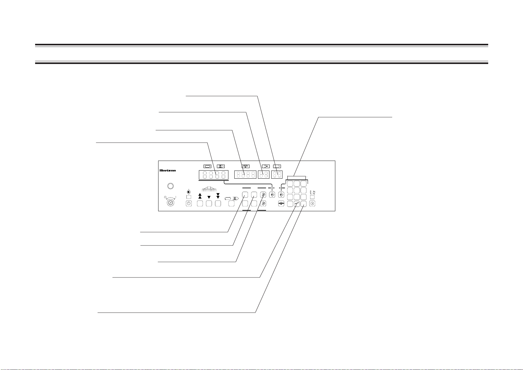
APC-T61
HYDRULIC CUTTER
1-2 Operation Panel Descriptions (T61)
Step Number Display
Program Number Display
Presetting Size Display
Current Position Display
This display shows the backgauge
current position.
Repeat
Current position
HYDRULIC CUTTER
Program Forward Button
Program Backward Button
Program Delete Button
Decimal Point/Clear Key
The decimal point is input in the first press and
the number is deleted for the delete key in the
second press.
Numeric Keypad
Setup
Put-out
Memory
Presetting
P
S
Program
P+-
S+-
Setup
No More
Memory Opar Error
?
Program No.
Delete
Step.No.
Memory
?
Push-out
789
456
123
.
0
E
c
Replacing
knife
ON
Enter Key
When this key pressed after inputting the number,
the backgauge moves to the set position.
1-6
Page 15
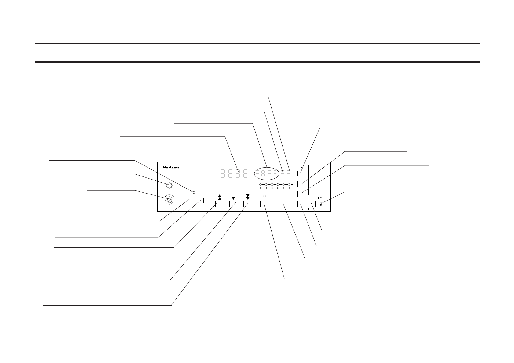
APC-M61
HYDRULIC CUTTER
1-3 Operation Panel Descriptions (M61)
Program Number Display
Step Number Display
Current Position Display
This display shows the backgauge
current position.
Hydraulic Pressure Lamp
Power Lamp
Key Switch
Hydraulic Pressure ON Button
Hydraulic Pressure OFF Button
High Speed Backward Button
This button is used to move
backgauge backward at high
speed.
Low Speed Forward Button
This button is used to move backgauge
forward at low speed.
High Speed Forward Button
This button is used to move backgauge
forward at high speed.
Presetting Size Display
Current Position Display
Power
Hydraulic
Backgauge Travel
Memory
Program No. Step No.
Presetting
Step
1 2 3 4 5 6
Memory Delete
Repeat / Setup
Step Forward Button
Size Memory Button
Push-out Memory Button
Knife Operation Mode Select Switch
This switch is used to replace knife.
In normal operation, this switch must be set
Step Forward
Size
Memory
Push-out
Memory
Program
Forward
Replacing Knife
Be sure to set "knife Angle
Adjustmant" knob and "Knife
Operation Mode" select
switch to each "Replacing
Knife"Position
Cutting Operation & Knife
Vertical Adjustment
Be sure to set "knife
Operation Mode" select
switch to "cutting"
position
knife Operation
Program Extension
Mode
Replacing
Knife
Cutting
to the cutting mode.
Program Extension Button
Program Forward Button
Memory Delete Button
Repeat/Setup Select Button
In normal operation, this switch must be set to the
repeat mode. The above repeat/Setup Lamp lights up.
The size memory button must be set to the setup mode.
(The above setup Lamp lights up.)
1-7
Page 16
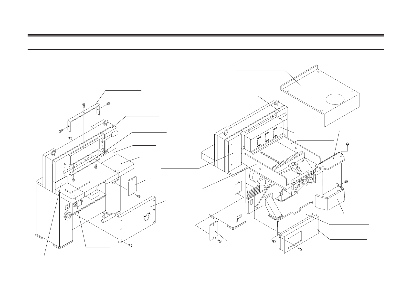
1-4 Cover Descriptions
Backgauge Cover
M013345-02
Upper Cover
Rear Cover L
Front Cover
Plate L
Table L
Lower Cover
Plate R
Table R
Small Cover
Rear Cover R
Side Gauge R
Front Cover L
Small Cover
Control Box
Side Gauge L
Back Cover B
Back Cover A
Back Cover U
Back Cover L
1-8
Page 17
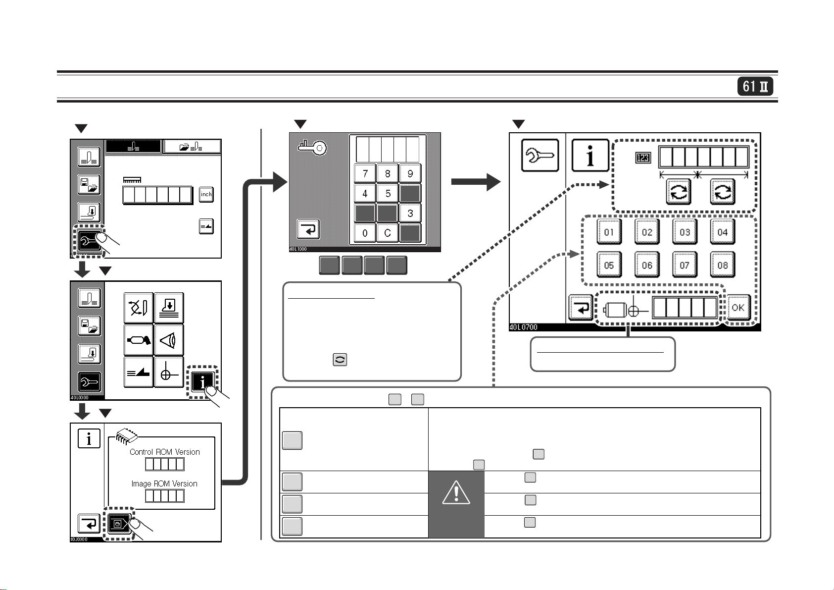
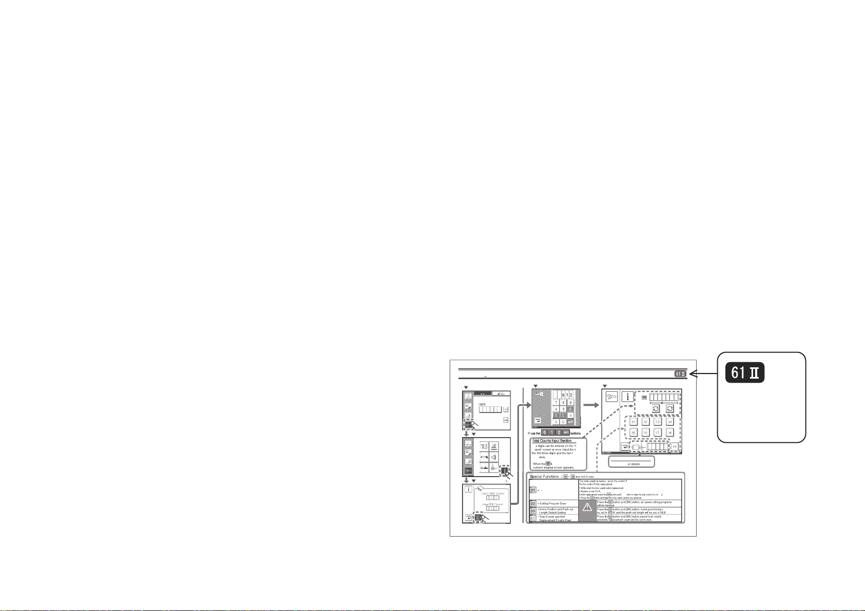
1-5 Entering Service Screen
"Normal Cutting" Screen
"Maintenance" Screen
"Information" Screen
"Numeric Keypad" Screen
612
6
2
1
ent
.
ent
05
08
- are not used.)
(
The total counts is memorized on the control P.C.B.
When replacing the control P.C.B.,
1. Write down the total counts before replacing the P.C.B.
2. Replace a new P.C.B.
3.
4. Press the button and input the total count number you wrote down.
CAUTION
Press the buttons.
6 1 2
Total Count Input
Up to five digits can be entered using the
"numeric keypad" screen at once. Input the
numbers the first three digits and the last
four digits separately
When the button is pressed, the
numeric keypad screen appears.
Special Functions
= Total Count Setting
01
= Cutting Program Clear
02
=
Resetting Home Position and
03
Push-out Length to Default
=
Total Count and Count after
04
Replacing Knife
"Service" Screen
Motor Home Position Display
Refer to 1-7 for details.
After replacement, press the button and the [OK] button to clear the total counts of a new P.C.B.
01
Press the button and the [OK] button. Saved cutting programs will be
deleted completely. Deleted cutting programs cannot be restored.
Press the button and the [OK] button. Home positioning value will be
set to 620.0, and the push-out length will be set to 50.0.
Press the button and the [OK] button. Memorized total counts and
count after replacing knife will be set to zero.
04
02
03
04
1-9
Page 18
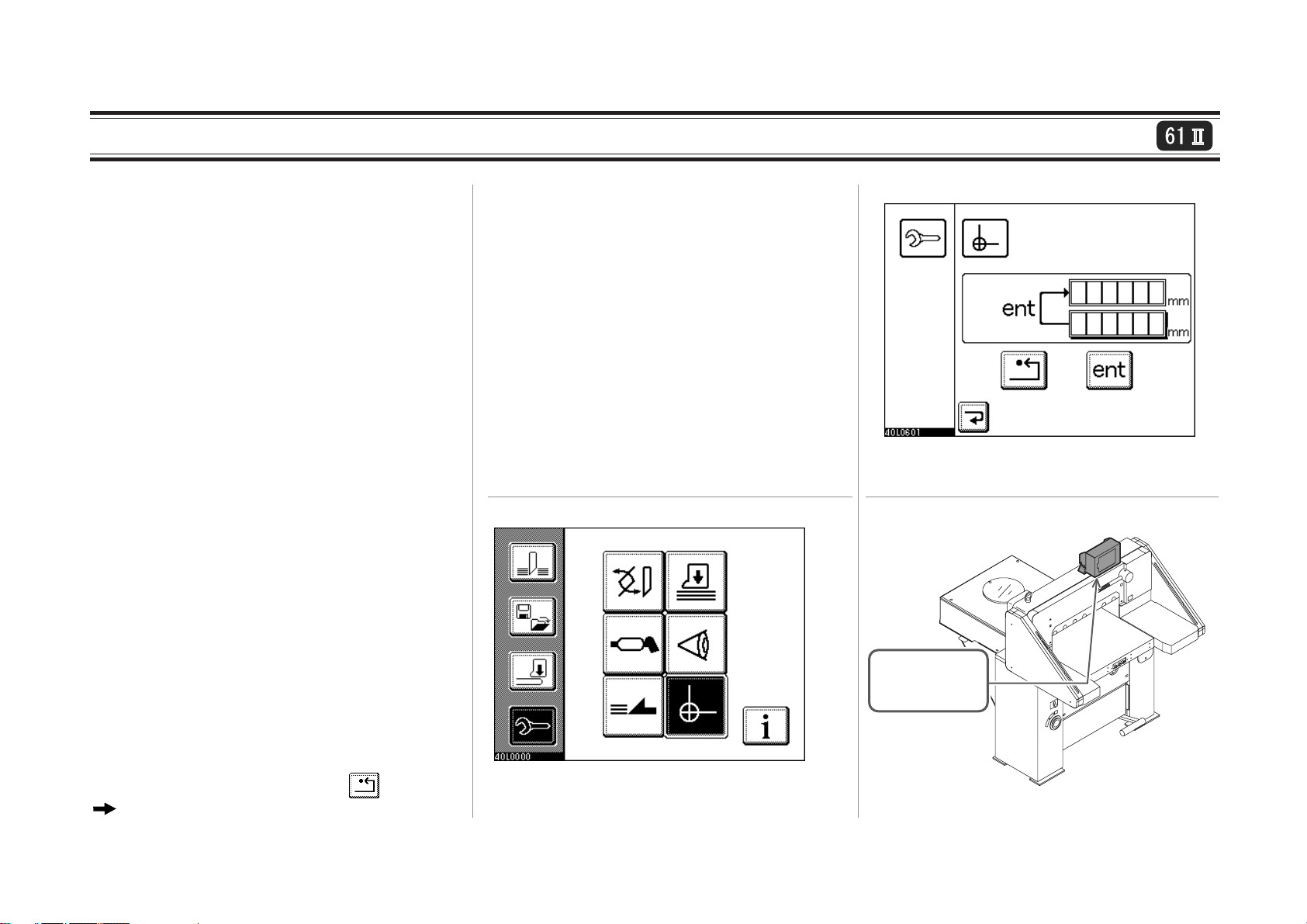
1-6 Calibration of Home Position
1. Set the cutting length to 100.0mm.
- This is the temporary value for comparing the
set value with the actual cut length.
2. Cut some sheets.
- Do not align the sheets on the side guide. Align the
sheets only on the backgauge properly, and cut.
3. Measure the dimension of cut sheets.
- Measure the dimension of the sheets by one
decimal place. 100.6mm is given for an example here.
4. Obtain the correction value.
- Correction value is a half of the difference
between the set value and the actual cut length.
- The actual cut length is 100.6mm. Therefore,
the correction value is 0.3mm.
5. Enter a new home position. (Fig.2)
- Show the Backgauge Calibration screen.
(Fig.1, Fig2)
- Add or subtract the correction value which was
calculated in step 4 to or from the current home
position value, and enter the new home position
value. (When the actual cut length is larger than
the set value, substract the correction value.)
In the case of the example, enter the value which
is subtracted by 0.3 and press the button.
The backgauge will move to the new home
position.
6. Check.
- Follow the steps 1 through 3 and check that the
set value matches the actual cut length.
7. Rewrite the home position sheet.
- The home position sheet is attached to the
bottom of the control panel box shown in Fig.3.
Rewrite the new home position on it.
504007
1_6_1A
Fig.1 "Maintenance" Screen
504007
1_6_1B
Fig.2 "Backgauge Calibration" Screen
The home position
sheet is attached to
the bottom of the
control panel box.
504007
1_6_1C
Fig.3 Location of the Home Position Sheet
1-10
Page 19
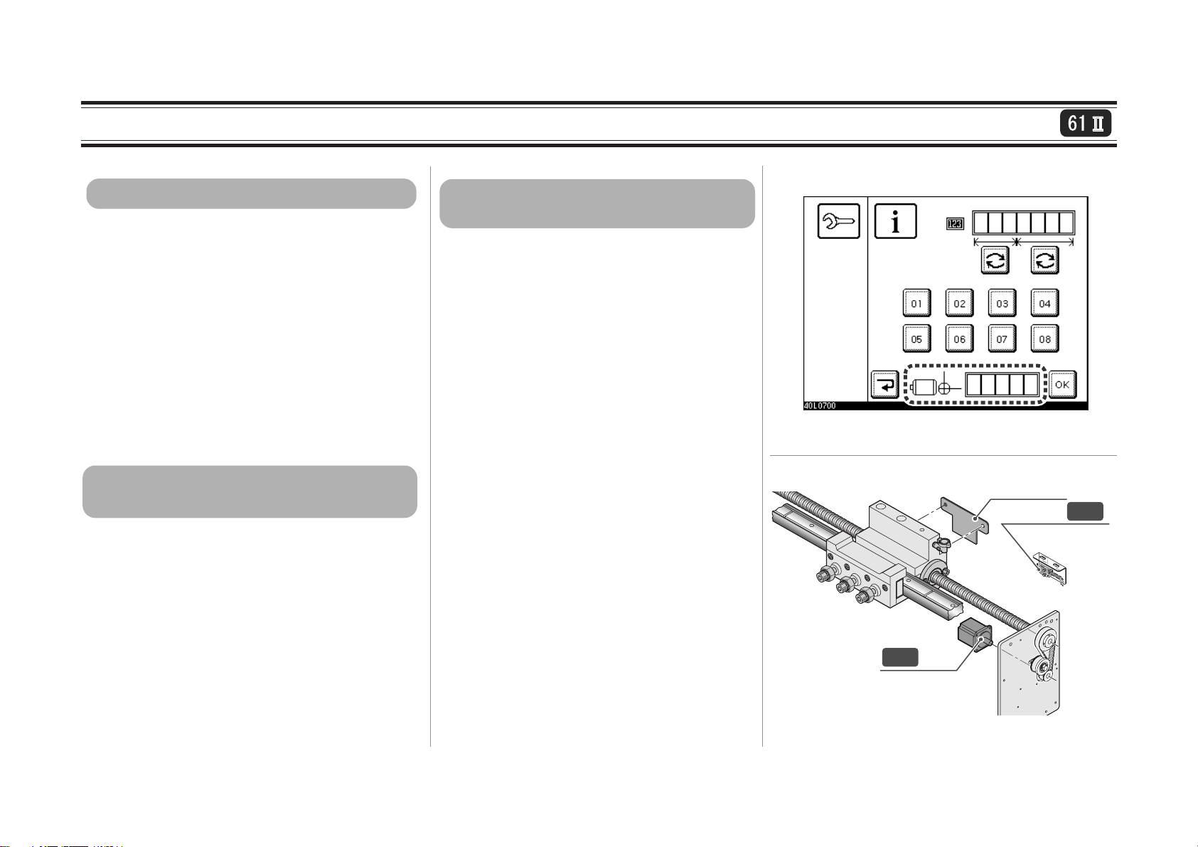
1-7 Checking Motor Home Position Distance
504007
1_7_1A
404007
1_7_1B
Home Position Sensor
Sensor Plate
B21
Servo Motor
M20
Explanation of "Home Positioning"
1. At first, the backgauge moves backward and
B21 home position sensor (Fig.2) detects the
sensor plate and turns on.
2. When B21 turns on, the servo motor M20
rotates in the reverse direction and moves the
backgauge forward, and B21 turns off.
3. The motor stops at the position where Z-phase
from the encoder is detected for the first time
in one rotation of M20. This position is the
home position.
- The encoder is housed in M20.
Explanation of "Motor Home Position
Distance"
- The motor home position distance is the
distance between the position which the B21
home position sensor turns off from on and
the position where the Z-phase from the
encoder is detected for the first time in one
rotation of M20. (steps 2 and 3 above).
- One rotation of M20 servo motor is set to 250
in APC-61II. The position of the home position sensor B21 is set so that Z-phase will be
detected at the middle of the motor rotation.
Therefore, the motor home position distance
should be around 125. (Fig.1)
Checking the Motor Home Position
Distance
- The Z-phase cannot be detected correctly
around the area that the B21 home position
sensor turned off from on, and the boundary
line of the first and second rotation of M20.
If the Z-phase appears at these areas, the
encoder may misread it, and
phase which appears next. This will set the
home position to the wrong position.
Therefore, checking the home position dis-
tance is necessary to make sure the encoder
reads Z-phase correctly in the stable area.
detects the Z-
Fig.1 "Service" Screen
Fig.2 Home Position Sensor B21
1-11
Page 20

This page is intentionally left blank.
1-12
Page 21

2. Troubleshooting
2-1 blinks on the Display (Backgauge Does Not Operate) .........2-2
2-2 Cut Size is Not Equal ...................................................................2-6
2-3 Knife Does Not Lower (Clamp Does Not Lower Either) ..........2-8
2-4 Knife Does Not Lift ....................................................................2-11
2-5 Clamp Lowers but Knife Does Not Lower...............................2-13
2-6 Clamp Does Not Lower Though Foot Pedal Is Stepped On. ..2-14
2-7 Backgauge Does Not Operate....................................................2-15
2-8 Backgauge Does Not come Forward (But goes backward) ....2-17
2-9 Backgauge Operates By Itself ...................................................2-18
2-10 Nothing Is Shown on Displays.................................................2-19
2-11 Hydraulic Pressure Does Not Operate....................................2-20
2-12 Knife Is Down before Operation........................................... -2-21
2-13 Knife Lower Limit Position Varies .........................................2-22
2-14 Backgauge Does Not Move (61II) ..........................................2-23
2-15 Error Code (61II) .....................................................................2-24
2-1
Page 22
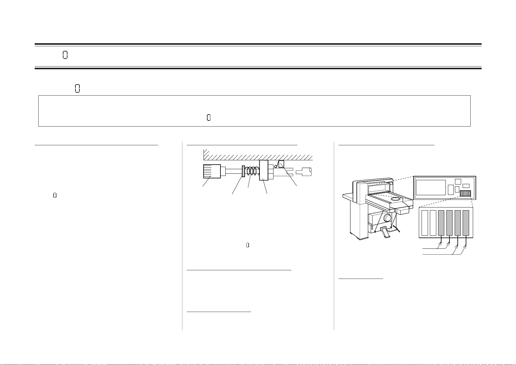
2-1 blinks on the Display (Backgauge Does Not Operate) Part 1
Why does blink on the display ?
Backgauge is traveled by the screw shaft which is driven by motor. Encoder is installed directly at the back end of the screw shaft, and
the operation distance of backgauge is controlled by counting the number of pulse from the encoder. In case that pulse signal does not
come from encoder while the backgauge is moving, blinks on the display inform to the trouble.
Backgauge is at the front limit position.
When backgauge is at the front limit position
(in normal case about 25mm, when support
plate is fixed about 75mm), limit switch is on.
When turning the power switch on this condition, blinks on the display.
After moving the gauge a little backwards with
adjust knob, turn the power switch on again.
Adjust knob remains being pressed
Adjust Knob
Snap Ring
Spring
Bearing Unit
Micro Switch
In normal case, the adjust knob is pressed by
compression spring to the operation side.
Even if you try to move the backgauge forwards or backwards when the adjust knob
remains being pressed for some reasons, motor
does not drive and
blinks on the display
because the machine is in manual mode.
Shaft of knob is difficult to move.
When the knob does not move smoothly
forwards and backwards, check bearing unit.
Lubricate when movement is dull.
Snap ring unfastens.
When snap ring (STW-20) unfastens, fix it
again.
Compression spring is broken.
When compression spring is broken, replace it
with a new one.
2A2A5A5A5A5
A
High Speed Motor Fuse
Low Speed Motor Fuse
Fuse is blown.
When motor protection fuse is blown, screw
shaft does not operate and no pulse rises from
encoder. Replace fuse according to Ò4-22Ó and
observe it.
2-2
Page 23
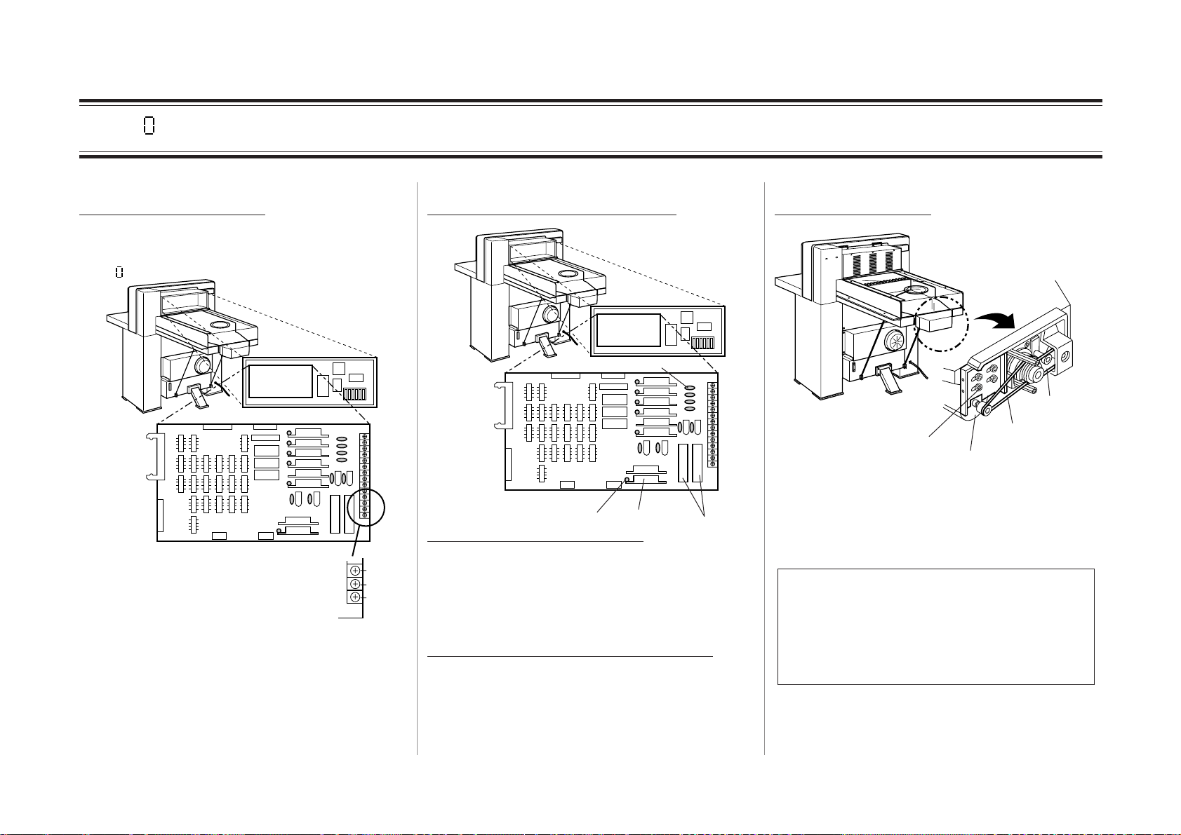
2-1 blinks on the Display (Backgauge Does Not Operate) Part 2
Phase of power is lacking.
Even if one of the three-phases AC power
results in open phase, motor does not operate
and
blinks on the display.
Control Box
1
2
3
4
5
6
T
S
R
Check input voltage which comes to every
section of this terminal board between R-S, ST, and T-R.
When there is no voltage even at one point,
original power is in open phase.
There is problem in control board.
Control
Box
Varistor
1
2
3
4
5
6
SSR
LED
Cement Resistance
Cement resistance is damaged
When switching the motion of the backgauge
(forwards or backwards), short circuit exists
momentarily and this cement resistance can be
damaged. In this case, replace P.C.B.
LEDs from No.1 to No.6 do not turn on.
When LEDs from No.1 to NO.6 showing
operation of knife, clamp, and backgauge turn
on normally, input signals are OK. If there is
no problem in output motor, SSR may has a
problem. Replace P.C.B.
Backgauge belt is cut.
Low Speed Belt
High Speed Belt
Motor Blacket
High Speed Motor
When belt is cut or overturned, power is not
transmitted and screw shaft does not drive.
Therefore, no pulse rises from encoder.
Replace belt with a new one.
As for high speed belt for S/N 103001 or
above, a new wider belt is used which is hard
to overturn. To attach this wider belt to a
previous machine, gauge base and motor base
also must be replaced.
(In case of order, please notice it.)
2-3
Page 24

2-1 blinks on the Display (Backgauge Does Not Operate) Part 3
Coupling of encoder unit is broken
Screw Shaft
Coupling
Encoder
Set Screws
When coupling is broken or set screws are
loose, rotation of screw shaft is not transmitted
to encoder and no pulse rises.
When coupling is broken, replace it with a new
one.
When set screw is loose, fasten it again.
Adjust knob is heavy
Gauge Rail
Adjust Knob
Fix Nut
Adjust Nut
Screw Shaft
Adjust nut and fix nut prevent screw shaft
returning (backlash) of the backgauge. When
there is problem in screw shaft, nuts or guide,
screw shaft is hard to move and normal pulse
does not rise. Therefore,
blinks on the dis-
play.
Oil on rail and screw shaft is running out.
When oil is running out, lubricate operating
the backgauge for-and backwards to circulate
oil.
There are some foreign objects on rail and
screw shaft.
When there are some foreign objects such as
paper dust, wipe them off and lubricate
enough.
There is problem in encoder.
Encoder is very delicate. When its shaft bends
because of external shock, it does not operate
correctly, even if it is connected with coupling.
Stay
Coupling
Encoder Bracket
Encoder
Screw Shaft
Axis difference or bent of shaft
should be within 0.1mm.
When there is an axis difference as shown in
the drawing, replace not only the coupling but
also the bracket and the stay.
There is contact failure or breaking of cable
from encoder.
Check the voltage between terminal 6 and 8 on
the terminal board 1 (refer to page 7-11) while
rotating the adjust knob slowly.
If the voltage changes
while rotating the knob
signal is output
from encoder normally.
87654
2-4
Page 25
2-1 blinks on the Display (Backgauge Does Not Operate) Part 4
Motor has burned out
Backgauge is moved by 2 motors. Above all,
high speed motor repeats driving in the normal
and reverse direction according to using condition. For each motor circuit, there is 5A fuse.
However, after using for many years, motor
insulation weaken gradually and motor coil
burns out without blowing of fuse.
Control Box
6
High Speed
TAN-1
5
4
3
2
1
Low Speed
Motor
A2016
VC-1
A 19151311
Motor
14 12
To check motor coil,
For high speed motor:
Check continuity among pins 4, 5, 6 on TAN-1
on control board.
For low speed motor:
Check continuity among terminals 12, 14, 16
on electromagnetic contactor VC-1 in control
box.
Brake surface smuts.
Brake
Encoder
0.15 to 0.3mm
Coupling
Armature
There is a gap between brake and armature for
0.15 or 0.30mm. when brake surface smuts
with metal powder because of surface wear,
semi-brake condition occurs and drive system
of backgauge becomes heavier. In this case,
clutch operation becomes dull and correct
pulse does not rise. Therefore,
blinks on the
display. Remove the metal powder with compression air or wipe off paper.
2-5
Page 26
2-2 Cut Size is Not Equal Part 1
Backgauge position is determined only by
high speed for- and backward buttons.
When backgauge is operated only using the
high speed forward or backward button, the
backgauge can not stop in the correct position
because of overrun. Determine precious position using low speed forward button or forward operation with adjust knob.
Set screw of coupling is loose.
Brake
Set Screws
Coupling
Encoder
When set screw is loose, rotation of screw
shaft is not transmitted to the encoder accurately, As a result, the size indicated on the
display becomes different from the actual
cutting size.
Adjust it referring to ÒAdjustment of Cut
SizeÓ, from 3-1 to 3-3.
Encoder
Backgauge driving belt is loose.
Low Speed Belt
Motor Bracket
High Speed Belt
3 to 4mm
2 to 3mm
High Speed Belt
High Speed Motor
Motor Pulley
Low Speed Belt
The high speed belt is bent by 2 to 3mm, low
speed belt 3 to 4mm, when the part pointed
with an arrow is pressed by 1kg force.
Tension of high speed belt can be adjusted by
position of motor bracket, low speed motor by
idle pulley. Adjust able range of idle pulley
becomes larger when it is attached upside
down.
2-6
Page 27
2-2 Cut Size Is Not Equal Part 2
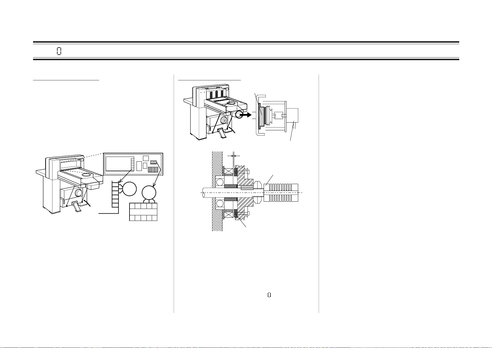
24VDC is not output from power supply.
PW-24
Power Supply PW-24
If output voltage of power supply PW-24 is
too low, the backgauge is delayed moving or
stop and the cumulative defference gets larger.
Check whether there is 24VDC output between 1 and 2 . Check whether there is
100VAC input between 4 and 5 . When there
is not 24VDC output in spite of 100VAC
input, replace power supply.
Gap of clutch or break is not correct.
Operation Side
0.15 to 0.30
0.2 to 0.3
12345
Brake
Gap of brake should be 0.15 to 0.30 mm.
Gap of clutch should be 0.2 to 0.3 mm.
Clutch
When gap of brake or clutch is not in these
ranges, the time lag results in the motion of the
screw shaft. Therefore, defference between
the indicated size on the display and the actual
cut size results.
Adjust it to correct gap.
Or when there is foreign object such as metal
powder on friction surface, remove it with
compression air or wipe off with paper.
2-7
Page 28
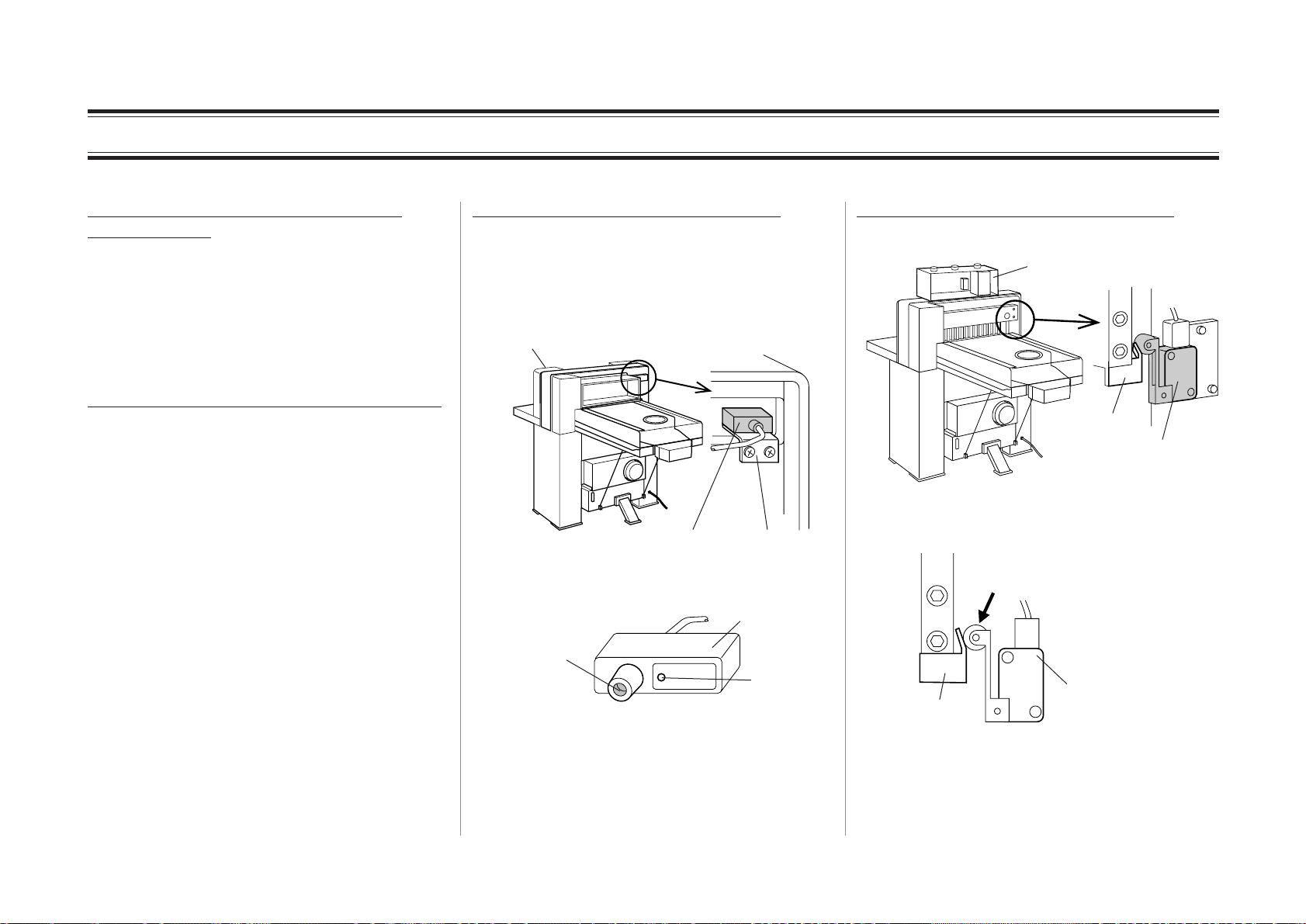
2-3 Knife Does Not Lower (Clamp Does Not Lower Either) Part 1
Cutting button A and B are not pressed
simultaneously.
For safety, when the timing to press cut buttons A and B differs more than 0.5 second, the
machine judges the abnormal operation and
hydraulic system does not operate. Press them
simultaneously (within 0.5 second).
There is a problem with cutting button A or B.
When each of cuttig button is pressed separately and slowly, it sounds click. When there
is no sound, there is mechanical problem or of
switch itself. Replace the cutting button
switch.
The cable from cutting button switch is connected with the machine under the front table.
Disconnect this connector and check the continuity with a tester. If there is the continuity
with cutting button pressed, it is OK. If there is
no continuity, replace cutting button switch.
When LED L2 and L4 on control board (See
Ò7-4 Control BoardÓ) lights for a moment and
go out again at the moment of pressing cutting
button, knife or clamp does not reach to the
upper limit position. See the next description.
Knife is not at the upper limit position.
The cutting operation does not start when
either knife or clamp is not at the upper limit
position. Check the sensor for upper limit
whether knife is at the upper limit position is
observed by sensor.
Front Cover
Sensor
Fixing Blacket
Remove front cover and check whether sensor
lamp is on.
Sensitive Area
Sensor
Lamp
When the lamp is on, knife is at the upper limit
position. When the lamp is not on though
knife is at the upper limit position, put a piece
of metal to sensitive of the sensor. If the lamp
turns on, sensor operates properly. Lower the
sensor bracket.
Clamp is not at the upper limit position.
Control Box
Dock
Lamp Upper Limit Position
Detecting Switch
The limit switch detecting the clamp upper
limit position should be on.
When this actuator is turned to the
right, there must be no detection
sound.
Dock
Lamp Upper Limit Position
Detecting Switch
Or check continuity between 8 and 9 of CON1
on control board with tester.
2-8
Page 29
1
2
3
4
5
6
2-3 Knife Does Not Lower (Clamp Does Not Lower Either) Part 2
APC-M61
HYDRULIC CUTTER
APC-T61
HYDRULIC CUTTER
There is an obstruction between beam
guards.
Beam Guards
When there is an obstruction on the optical line
between beam guards, the beam is blocked and
safety function operates. Therefore, knife does
not lower.
There is trouble with foot switch control
board.
If board is replaced and problem disappeared,
some of relays on the board has the contact
failure.
Ray
Obstruction
Some of switches on operation panel remains
on.
(APC-M61)
Power
(APC-T61)
Hydraulic
Repeat Setup
Current position
Current Position Display
Backgauge Travel
Put-out
Memory
Presetting
P
S
Presetting
1 2 3 4 5 6
Repeat / Setup
No More
Memory
?
Program No.
Program
Delete
P+-
S+-
Setup
Memory
Program No. Step No.
Step
Memory Delete
Opar Error
?
Step.No.
Memory
Push-out
Step Forward
Size
Memory
Push-out
Memory
Program
Forward
789
456
123
.
0
E
c
Replacing Knife
Be sure to set "knife Angle
Adjustmant" knob and "Knife
Operation Mode" select
switch to each "Replacing
Knife"Position
Cutting Operation & Knife
Vertical Adjustment
Be sure to set "knife
Operation Mode" select
switch to "cutting"
position
knife Operation
Program Extension
Replacing
knife
ON
Mode
Replacing
Knife
Cutting
For APC-M61:
Any of the step forward button, the size
memory button, and the push-out memory
button remains pressed.
For APC-T61:
After button is pressed, there is no sound and it
does not return.
When any of the switches are out of order or
remain pressed, the machine judges that it is in
the setting mode. Therefore, hydraulic system
does not operate.
2-9
There is problem in control board.
Control
Box
Varistor
SSR
LED
Cement Resistance
SSR (solid stay relay) or cement resistance is
damaged.
If its white exterior is broken or cracked because of heat, cement resistance get damaged.
And if there is continuity between the two
parts of the bottom in the following drawing,
SSR is out of order. However, no continuity
does not always mean normal.
If there is continuity,
SSR is out of order.
If this part is damaged, hydraulic pressure is
not applied. Replace the board.
If knife does not lower though hydraulic
pressure applied, check the hydraulic valve.
Page 30
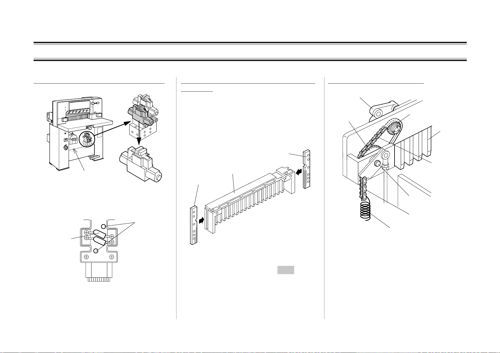
2-3 Knife Does Not Lower (Clamp Does Not Lower Either) Part 3
Hydraulic valve does not operate correctly.
[Valve Section]
Hydraulic Section
[Electromagnetic Valve]
Remove the apron cover under the table and
check whether LED of electromagnetic valve
turns on, when cutting button is pressed.
LED
Spark Killer
[Top of Electromagnetic Valve]
If LED turns on, the signal comes correctly.
The internal damage of electromagnetic valve
can be considered. Replace electromagnetic
valve.
Grease on clamp rails is not enough to move
the clamp.
Clamp lifts and lowers guided by right and left
rails. However, when there is not enough
grease between clamp and rail, clamp is difficult to move because of metal friction and does
not return to the upper limit position. When the
upper limit position of clamp is not detected,
cutting operation does not start.
Rail
Clamp
Rail
[Back view of the machine]
When there is enough grease on part of
right and left rail, there is no problem. When
there is little grease, lubricate with a grease
gun. (See Ò6-4 LubricationÓ in operation
manual.)
2-10
There is problem in clamp link.
Link A
Sprocket B
Spring
Sprocket A
Clamp
Chain
Hook shaft
Chain
Check the followings.
Chain is damaged.
Sprocket A or B is detached from shaft.
Spring is detached or loose.
(For old model link A) needle bearing is detached. When an old model of the machine has
link A.
When there is problem with any of these parts,
clamp can not be lifted and return to the upper
limit position. When clamp is not the upper
limit position, the machine can not start cutting
operation.
Page 31

2-4 Knife Does Not Lift Part 1
Ajusting Knife's
Lower Dead Point
Down UP
7
When cut buttons are pressed, first clamp lowers. Second, knife lowers to cut . After that, knife stops and does not lift again. (Clamp
does not lift either.) Or when you release your hands from cut buttons, knife lifts again. However, Step does not proceed automatically.
The depth of knife is too short.
[When knife resharpened for many
times is used]
Resharpened and shortened knife should be
lowered to cutting stick by loosening 2 screws
of knife holder according to “6-2 Knife Replacement” of operation manual. However, in
this case, the tip of knife does not reach to the
cutting stick, though 2 screws are lowered to
the lowest position.
In this condition, if cutting operation starts
with all 7 screws tightened, sensor can not
detect the tip of knife. Therefore, knife tries to
continue lowering.
Replace knife to new one and operate again.
Lift the knife with the cutting depth adjust
dial in advance. Otherwise new knife can cut
into the cutting stick.
Knife does not touch cutting stick when
replacing knife.
When replacing knife, loosen 2 screws of the
knife fastened at the lower limit position in
“Knife Replace Mode”, and lower knife until
the end of knife touch cutting stick, and fix
knife again. Otherwise, knife tries to continue
lowering during normal cutting operation,
because knife is not detected by the lower limit
sensor.
Screw
knife
No Gap
Cutting Stick
After replacing knife, the position of knife
lower limit position sensor is still lower.
Cutting Depth Adjust Dial
When using knife resharpened for many times,
the position of lower limit position sensor must
be adjusted depending on shortened length of
knife. However, if the position of lower limit
position sensor does not change after replacing
knife with a new one and knife lowered, knife
cuts into cutting stick. Therefore, knife is not
detected by sensor and hydraulic system continue operating so that knife continues lowering.
After releasing your hands from cut buttons
and knife lifts, adjust the position of lower
limit position sensor upward.
2-11
Page 32

2-4 Knife Does Not Lift Part 2
Knife lower limit position sensor does not
operate correctly.
WARNING
LED
Knife Exchange
Position Sensor
LED
Lower Limit
Position Sensor
When knife lower limit position sensor is out
of order with its switch off, it does not detect
knife at the detection point and no signal rises.
Therefore, the machine determines knife does
not reach the lower limit point and operates to
continue lowering knife.
Turn off the switch of hydraulic pressure
before the following operation. Otherwise heavy accident will result.
When knife is at the upper limit position,
measure the voltage between 4 and 5 of CON1
on the control board (See “7-5 Control Board,
Connector Layout) is 5VDC. Next, in this
situation, approach a ferrous piece within
2mm. If the voltage changes into 0V, the
sensor has no problem. (LED of the sensor
turns on.)
24V
7
6RED
5WHT
4Shield
3
2
1
Sensor
Output
0V
If the voltage remains 5VDC though ferrous
piece is approached, the sensor is out of order
with its switch off.
2-12
Page 33

2-5 Clamp Lowers but Knife Does Not Lower
Clamp operates only and knife never
operates, though cut buttons are pressed.
Cutting knife ON/OFF switch is on.
View A
Knife Lower Limit
Position Sensor
Cutting Knife
ON/OFF Switch
When cutting knife ON/OFF switch is on, only
clamp operates and knife does not operate. In
normal cutting operation, turn off this switch.
When pressed cut buttons, clamp lowers
at first and knife begins to lower. But
knife lifts before it is reached to the
lower limit and clamp also lifts.
Knife lower limit position sensor does not
operate correctly.
LED
Knife Exchange
Position Sensor
LED
Lower Limit
Position Sensor
[View A]
If knife lower limit position sensor shortcircuits to ON side (close side), it determines
that knife has reached lower limit position
though it does not. Therefore, when knife
begins to lower it soon returns to the upper
limit position.
WARNING
Turn off the switch of hydraulic pressure
before the following operation. Otherwise heavy accident can result.
Check the voltage between 4 and 5 of CON1
on the control board (See “7-5 Control Board,
Connector Layout”). If it is 5VDC, sensor has
no problem. However, if it is 0VDC, sensor
short-circuits to ON (close) side.
24V
7
6RED
5WHT
4Shield
3
2
1
Sensor
Output
0V
2-13
Page 34

2-6 Clamp Does Not Lower Though Foot Pedal Is Stepped On.
RL
Joint or rod has problem.
Rod End
Rod
Rod End
Upper or lower rod end is loose and detached
from rod. Or rod is broken.
In either case, because the stepping force on
foot pedal is not transmitted to clamp, that is
why clamp does not lower.
If rod is broken, replace it and adjust to the
right position according to Ò4-10 Replacing
RodÓ.
For machines of S/N 010999 or below, the
drawing of rod is as follows.
To replace it with the present one, not only
upper and lower rod ends and rod but also
hook on parts book Fig.3-30 (M013220-00)
need to be replaced together.
Stepping Position Detecting Micro switches
are out of order (For T-58.)
Foot Pedal
Micro Switch
Cam
Check 2 micro switches detecting the position
of foot pedal. If they do not turn on or off
though foot pedal is stepped on, check whether
cams are loose. If the switches do not turn on
or off though cams are not loose, micro
switches are out of order.
2-14
Page 35

1
2
3
4
5
6
2-7 Backgauge Does Not Operate Part 1
Power is distributed to each motor.
Control Box
6
High Speed
TAN-1
5
4
3
2
1
Low Speed
Motor
A2016
VC-1
A 19151311
Motor
14 12
Check whether 200V voltage is output among
these motor terminals. When there is no voltage, check whether power switch (breaker) is
on or the following fuses are blown.
Motor coil is burnt out.
Remove the motor terminals from each terminal board and check continuity among 3
cables.
M
A
B
C
When there is no continuity in any of A, B,
and C, coil is burnt out inside the motor.
Replace motor.
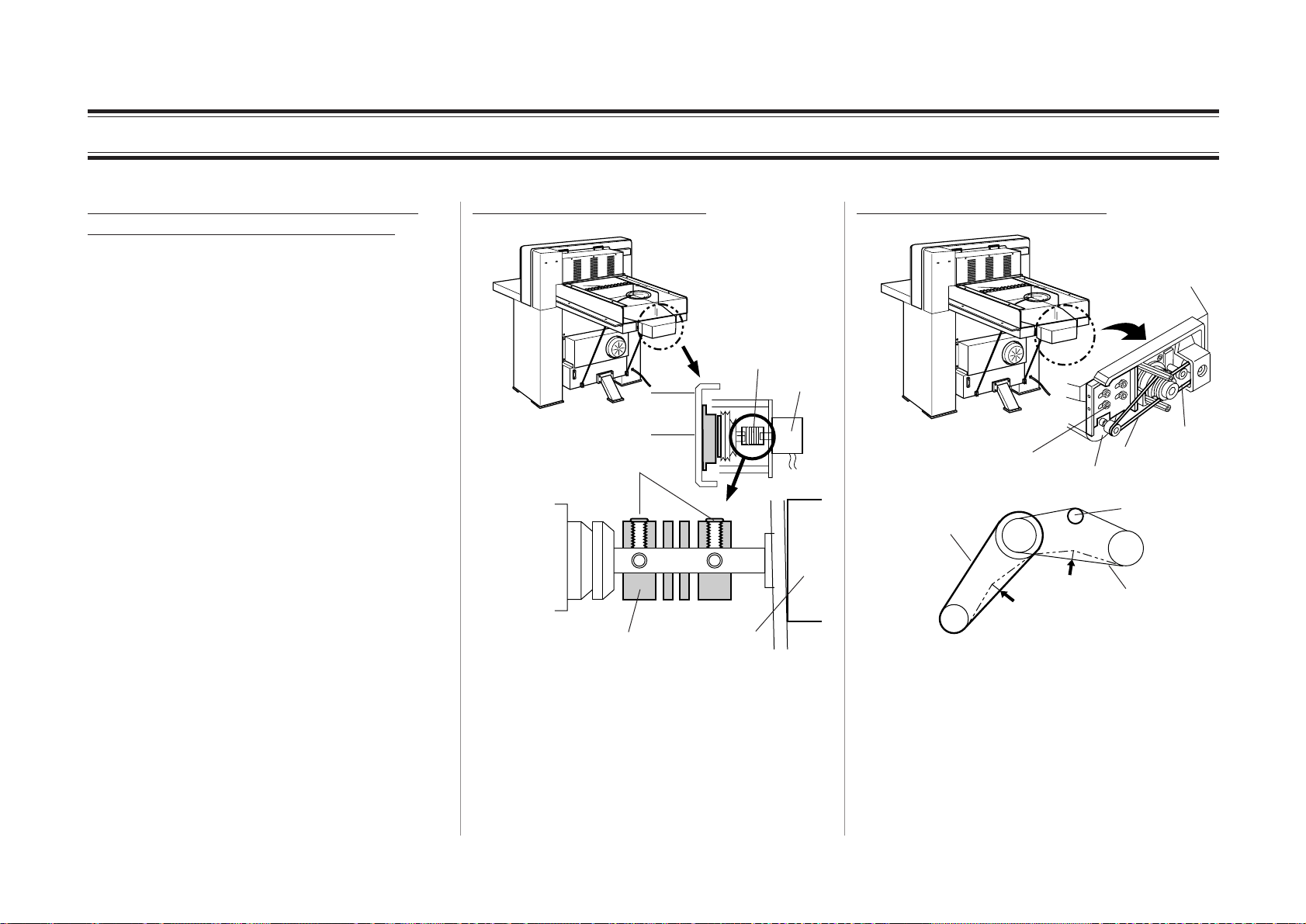
Backgauge driving belt is cut.
There is problem with control board,
Control
Box
Varistor
SSR
Cement Resistance
When the cement resistance (rectangle shape
in white) is damaged, replace the whole board.
High Speed Motor Fuse
Low Speed Motor Fuse
2A2A5A5A5A5
When LED 5 (backgauge forward) and LED 6
(backgauge backward) turn on, control signal
from the board rises correctly. The damage of
A
High Speed Belt
If belt is cut, replace it.
Low Speed Belt
2-15
SSR can be considered. Replace it with the
board.
Page 36

2-7 Backgauge Does Not Operate Part 2
APC-M61
HYDRULIC CUTTER
APC-T61
HYDRULIC CUTTER
Adjust knob remains pressed.
Adjust Knob
Snap Ring
Spring
Bearing Unit
Micro Switch
Backgauge adjust knob is normally pushed to
the operation side by spring. However, when
knob remains pressed for some reason, micro
switch turns on and the machine changes into
manual mode. Therefore, backgauge does not
operate.
When the adjust knob remains pressed and
does not return, check whether there is problem with snap ring, spring, and bearing.
Any of switches on operation panel remains
on.
(APC-M61)
Power
Hydraulic
(APC-T61)
HYDRULIC CUTTER
Repeat Setup
Current position
Current Position Display
Backgauge Travel
Put-out
Memory
Presetting
P
S
Program
P+-
S+-
Setup
Memory
Program No. Step No.
Presetting
Step
1 2 3 4 5 6
Repeat / Setup
Memory Delete
No More
Opar Error
Memory
?
?
Program No.
Step.No.
Memory
Delete
Push-out
Step Forward
Size
Memory
Push-out
Memory
Program
Forward
789
456
123
.
0
E
c
Replacing Knife
Be sure to set "knife Angle
Adjustmant" knob and "Knife
Operation Mode" select
switch to each "Replacing
Knife"Position
Cutting Operation & Knife
Vertical Adjustment
Be sure to set "knife
Operation Mode" select
switch to "cutting"
position
knife Operation
Program Extension
Replacing
knife
ON
Mode
Replacing
Knife
Cutting
For APC-M61:
Any of step forward button, size memory
button, and push-out memory button remains
pressed.
For APC-T61:
After button is pressed, it can be felt that the
button returns back with a sound.
When any of the switches is out of order or
remains pressed, the machine determines
setting mode is operated. Therefore, backgauge
does not operate.
When the switch cap locks, return it to normal
condition. When the switch itself is out of
order, replace the board itself. (When replacement of switch itself only is possible, replace
separately.)
2-16
Page 37

2-8 Backgauge Does Not come Forward (But goes backward)
Limit switch remains ÒONÓ.
SW2
Limit switch 1
SW3
Limit switch 2
(When pressure support
plate is used.)
Limit switch 1 or 2 shows normally ÒClosed
(=NC)Ó. When backgauge moves forwards
and activates limit switch, it shows ÒOpenÓ
and stops backgaugeÕs forward motion. If the
actuator of limit switch is on or connector is
disconnected, the control board determines the
detection circuit is ÒOpenÓ and backgauge
can not operate forwards. (Backgauge can go
backwards.)
Check of limit switch: See Ò7-5 Control
Board, Connector LayoutÓ.
GRN
12
13WHT
14empty
15BLK
16
CON3
Control Box
When there is continuity between 16 and 15 of
CON3, there is no problem with SW2. When
there is continuity between 16 and 13, there is
no problem with SW3.
There is problem with high speed motor.
Power is supplied to the high speed motor.
Coil of high speed motor is burnt out.
High speed belt is cut.
There is problem with control board.
As for these 4 symptoms, follow the description in Ò2-7 Backgauge Does Not Operate.Ó
2-17
Page 38

2-9 Backgauge Operates By Itself
12345
PW-05
Check knife lower limit position sensor.
LED
View A
Knife Lower Limit
Position Sensor
[View A]
When ÒRepeatÓ mode is selected and lower
limit position sensor is out of order with ON
side (close side), the sensor determines
wrongly that knife reached lower limit position
soon after knife has begun to lower. Therefore, knife returns to upper limit position and
backgauge move to the position for the next
step.
WARNING
Turn off the switch of hydraulic system
before the following operation. Otherwise heavy accident will result.
24V
7
Sensor
Output
0V
When the voltage between 4 and 5 of CON1
on the control board (See Ò7-5 Control Board,
Connector LayoutÓ) is 5VDC with the knife at
upper limit position, there is no problem with
the sensor. When the voltage is 0VDC, the
sensor short-circuits to ON side. Replace the
sensor.
6RED
5WHT
4Shield
3
2
1
The voltage of power supply (PW-05)
declines.
CON7
Control Box
Power Supply (PW-05)
When the voltage between 1 and 2 becomes
lower than 5V, the operation of CPU board
becomes unstable and operate wrongly. When
under 5V, adjust the volume on this power
supply board to supply the voltage between
5.15 and 5.25V to the CPU board. The voltage
can be measured also on CON7 of the control
board. (See Ò7-5 Control Board, connector
LayoutÓ.)
When cable is pinched between power supply
and control board, cover of the cable tears and
the voltage can decline. In this case, put a
piece of paper for insulation between them.
2-18
Page 39

2-10 Nothing Is Shown on Displays
Fuse for electronic circuit is blown.
Control Box
2A2A5A5A5A5
A
Fuses for Electronic Circuit
When fuse for electronic circuit is blown,
P.C.B. does not operate and operation panel
records nothing.
Replace the fuse with a spare one in the control
box.
Distributor does not operate.
Check whether the breaker in the distributor is
on.
Check whether the fuse in the distributor is
blown.
There is problem with power switch.
Power Switch
Check the continuity of power switch.
2-19
Page 40

2-11 Hydraulic Pressure Does Not Operate
Thermal relay trips.
Thermal Relay
Control Box
14 6 4 2
Reset Button
Trip Bar
13 5 31
If there is excessive pressure on hydraulic
system, thermal relay operates and contactor
opens to shut the power off to protect the
hydraulic motor.
When thermal relay operates, trip bar is pushed
in. When green reset button is pressed, thermal
relay will be reset.
Contactor can not cut electricity because of
heat.
Thermal Relay
14 6 4 2
Contactor
13 5 31
When hydraulic pressure is not on,
There is electrification between 2 and 1 .
There is electrification between 4 and 3 .
There is electrification between 6 and 5 .
If there is electrification in any of these parts,
contactor can not cut electricity because of
heat. Replace thermal relay and contactor .
If hydraulic pressure switch is turned on in this
condition, the breaker of control box will
operate or the fuse will blow.
Any of Phases is Open.
The voltage 200V is not supplied among
contactor output terminals 1, 3, and 5.
5 3 1
When there is no voltage at any of the three
points, or when the voltage is declining to
about 100V (Open phase), the thermal relay
operates and hydraulic system does not operate.
Check the circuit between the plug of this
machine and the contactor.
Reset Button
2-20
Page 41

2-12 Knife Is Down before Operation
After finishing operation of the day before and
turning off hydraulic pressure, the oil in
hydraulic circuit return to the tank because of
slight leak of oil from valves. Therefore knife
lowers depending on the amount of leak
through the night. As a result, when turning
on the power on the next day and pressing
hydraulic pressure switch, knife lifts a little to
return to the upper limit position. If knife is
not lower than clamp before turning on hydraulic pressure switch, there is no problem
for safety and operation.
When knife is lower than clamp, a large oil
leak is occurring in hydraulic system.
Remove the cover of the machine and check
hydraulic system by the following procedure.
WARNING
Oil is leaking at hydraulic hose joint.
Touch the joint between hydraulic hose and
each hydraulic parts. If oil clings to your
finger, the connection of joint is not tight. Fix
the parts side by turning the pipe side.
Oil is leaking from hydraulic cylinder.
When oil is leaking from this part pointed by
an arrow, the problem with the cylinder packing can be considered. Replace cylinder or
disassemble the cylinder and replace rod
packing.
When replacing rod packing, replace
also dust wiper.If knife still lowers,
there is problem with interior
packing inside. Replace the whole
cylinder.
C spring to return the knife is cut.
C spring
I Bolt
Hydraulic Cylinder
When C spring is cut or loose, the force to
return the knife to upper limit position weakens and knife lowers even by a slight oil leak.
When spring is cut, replace it.
Turn power switch off before checking
hydraulic system.
2-21
Page 42

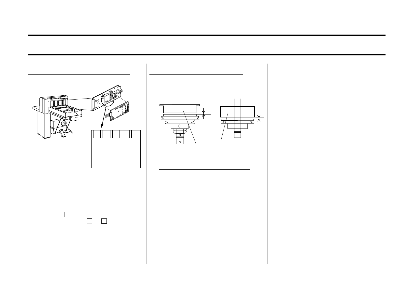
2-13 Knife Lower Limit Position Varies
[Cause 1: Oil temperature variation]
When this machine is operated for a long time,
oil temperature rises and viscosity weakens.
Therefore, the speed of hydraulic cylinder
becomes slightly faster.
When knife lowering speed becomes faster,
because lower limit position becomes lower,
lower limit position needs to be rised with the
cutting depth adjust dial. When operation
begins after long break, because oil temperature returns, uncutting occurs.
[Solution]
Because knife lower limit position changes
depending on the oil temperature variation,
adjust with cutting depth adjust dial for each
time. For S/N 103001 or above, because
hydraulic unit is renewed and oil cooler is
equipped as standerd, the temperature variation
does not occur.
The oil suited to ISO VG32 should be used.
[Cause 2: The timing of lower limit position
detection]
The signal is sent with about 10msec cycle in
this machine. Therefore, the time difference at
10m sec maximum between lower limit position detection and CPU exists.
The variation are caused by the knife moving
distance for this time.
But this variation is in allowable range.
2-22
Page 43

2-14 Backgauge Does Not Move
- Check that the drive mechanism of the
machine is not damaged.
Refer to 3-14 for details.
Check the items below.
1 The timing belt is not cut.
2 The idle shaft is fixed tightly.
3 The locking screw of the timing pulley is
not loose.
4 The key is attached on the spindle.
5 The locking screws of the servo motor are
not loose.
504007
2_14_1A
- Check that grease is applied.
Block
Gauge Rail
Refer to the drawing above and check the
items below.
1 Oil is applied to the spindle.
2 Grease is applied to the gauge rail.
Spindle
504007
2_14_1B
- Check that the electrical wiring is correct.
52
Q21
'
LL
2A
Q22
'
LL
2A
Q23
'
L
5A
(on the page 7-16)
M20
3
Servo Motor
54
A
55
To SD1
504007
2_14_1C
X24
WHT
BLK
T20
200V
WHT
11
BLK
22
07
0V
06
WHT
BLK
24V
2A
0V
WHT
LL
'
Q24
BLK
NN
'
5A
L
N
200V 500VA
Amplifier for
Servo Motor
A24
RED
RED
BLK
58
L
5657
RED
U
WHT
V
BLK
W
GRN
Refer to 7-14 for details
- Check at the display of A24 amplifier for
servo motor.
When the display does not show anything, go
to step 1 below. When the display shows an
alarm of A**, go to step 2 below. When the
display shows CL, go to step 3 below.
1. Refer to the electrical wiring above to check
the power circuit from transformer T20 to A24.
2. Follow the [Solution] on the displayed error
code A
3.
Remove the motor cover at the back of the
at section 2-15, No.1351.
**
machine, and turn the timing pulley by hand.
When you can turn it by hand, replace QPM-195
if the wiring and connection between A24 and
CON9 on QPM-195 are normal.
When you cannot
turn it by hand, the command from the P.C.B is
defective.
Replace control P.C.B. QPM-195.
2-23
Page 44

2-15 Error Code
】
- If an error code which is not included in the following table is displayed, it can be a communication error.
Error Code Error Details
101
801
Knif e Lower
Limit Error
Memory Error
Causes and Solut ions
【Cause】 The knife lower limit sensor B11 did not turn on, although a specific time has passed after the knife started to lower.
Check if the lower limit was set too low using the knife up and down adjusting dial. If the dial has not been op erated, check if the
lowering speed is slower than usual. If it is slower, go to following 1. If it is as usual, go to following 2.
1. Check if grease is applied to the knife holder. If it is OK, check if there is no foreign object on the sliding surface of the knife holder. If
there is no such object, the hydraulic system is defective. Check the system.
【Solution】
Cause
【
【
Information
【Solution】
】
Additional
2. Refer to section 6-6 to check the installing condition of B11. If it is OK, check B11 itself. If the LED of B11 blinks when B11 is turned
on or off (metal piece is fit completely to the detector of B11/ set apa rt from it), go to following 3. If it dose not blink, go to following 4.
3. Check if the LED5 on the control P.C.B. QPM-195 blinks when B11 is turned on or off. If LED5 blinks, although the signal reaches
normally from B11 to the P.C.B., the signal is not processed correctly. Replace QPM-195. If the LED5 does not blink, the wiring and
connection between B11 and CON5, pins 10 through 12 on QPM-195 is defective.
4. Replace B11 when the wiring and connection between B11 and CON5, pins 4 through 6 is normal. If the same error still occurs,
restore B11, and replace the control P.C.B QPM-195.
The set value of the saved data is out of range.
Data means job setting, backgauge home position and counter value.
】
If the cutting length is normal, this error can be ignored.
If this error appears repeatedly, turn off the main power for about 10 seconds and then turn it on again. If the same error still occurs,
refer to section 7-12 to replace the IC. If the same error still occurs, restore B11, and replace the control P.C.B QPM-195. After
replacing the IC or P.C.B., enter a home position again. The sheet on which home position is written is attached on the bottom of the
control panel box.
【Cause】 The program is full in the memory.
Additional
802 Memory Full
【
Information
Solution
【
99 courses and 99 processes can be saved. However, the capacity is limited. Not all can be saved.
Delete unnecessary programs. If this error appears although not many programs are memorized, replace the control P.C.B. QPM-195.
】
2-24
Page 45

2-15 Error Code
proj
g
p
Error Code Error Details
Safety Light
1051
Beam Sensor
ON Error
Photo Area
1061
Guard Sensor
ON E rro r
【
【
In form at io n 1】
【
In form at io n 2】
【
Solution
【Cause 】
【
Additional
In form at io n 1】
【
Additional
In form at io n 2】
【
Solution
【
】
Cause
Additional
Additional
】
Cause
】
】
Causes and Solutions
When B51L projector of the safety light beam sensor does not light, the B51R receiver turns on.
The APC-61II checks the B51 safety light beam sensor every time the cutting operation is done. It checks that the B51R receiver
turns on when B51L projector turns on, and when the projector turns off, the receiver turns off.
LED L41 on the control P.C.B. QPM-195 lights when the B51L projector lights. When B51L goes out, LED L41 does not light.
LED L4 2 on the control P.C.B. QPM-195 lights when B51L projector lights and the B51R receiver receives the light (th ere is no
object between the sensors).
It does not light when the receiver do es not receive the light (something is between the sensors) although the projector lights.
When the
Check the installing cond ition of B51R receiver of the sensor. Check the wiring and connection between B51R and CON13 on the
control P.C.B. If it is OK, replace the control P.C.B. QPM-195.
Although B50L projector of the sensor does not light, the B50R receiver of the sensor turns on. Or, the receiver detects as if all
beams are received although not all the beams are received.
The APC-61II checks the photo area guard sensor every time the cutting operation is done. It checks if lighting and receiving each
beam of the guard is detected correctly by sending test signals from the control P.C.B.QPM-195.
LED L2 2 on the control P.C.B. QPM-195 lights when B50L projector lights and the receiver receives all beams (there is no object
between the sensors).
It does not light wh en the receiver does not receive all beams (something is between the sensors) although the projector lights.
When LED L25 on the control P.C.B. QPM-195 lights, B50L photo area guard does not light.
When LED L25 on the control P.C.B. QPM-195
Check the wiring and connection between B50R receiver and CON13 on the contro l P.C.B.QPM-195. If it is OK, replace the control
P.C.B. QPM-195.
The knife upper limit sensor B12 did not turn on, although specific time has passed after the knife started to raise.
ector does not light, the L42 does not light.
oes out, B50L photo area guard lights and the guard function operates.
1151
Knife Upper
Limit Error
【
Solution
Refer to section 6-6 to check the installing condition of the knife upper limit sensor B12. If it is OK, check if the knife raising speed is
not slower than usual. If it is slower, go to following 1. If it is as usual, go to following 2.
1.Check if grease is applied to the knife holder. If it is OK, check if there is no foreign object on the sliding surface of the knife holder.
If there is no such object, the hydraulic system is defective. Check the system.
2.Check B12 knife upper limit sensor. If LED of B12 blinks when B12 is turned on or off (metal piece is fit completely to the detecto r
】
of B12/ set apart from it), go to following 3. If it does not blink, go to follow ing 4.
3.Check if the LED3 on the control P.C.B. QPM-195 blinks when B11 is turned on or off. If LED3 blinks, although the signal from B12
to the P.C.B. i s normal, the signal is n ot processed correctly. Replace QPM-195. If the LED3 does not b link, the wiring and
connection between B12 and CON5,
4. Replace B12 if the wiring and connection between B12 and CON5, pins 4 through 6 is normal. If the same error still occurs,
restore B12, and replace the control P.C.B QPM-195.
ins 4 through 6 on QPM-195 is defective.
2-25
Page 46

2-15 Error Code
Error Code Error Details
1351
Back gauge
Servo Error
Causes and Solutions
【Cause】 The control P.C.B. QPM-195 received an alarm signal from A24 amplifier of M20 servo motor.
Turn off the main power switch for 10 seconds and then turn it on again. If this error still appears, refer to the alarm numbers A** below
【Solution】
Additional
【
Information
Alarm A10
Alarm A12
Alarm A14
Alarm A15
Alarm A16
Alarm A17
Alarm A20
which is displayed on the screen of A24 amplifier. Regarding the mechanical troubles, refer to section 3-15 to check if enough grease
is applied to the spindle and the gauge rail. If grease is applied, remove the timing belt for the backgauge section and turn the spindle
manually to find the cause.
If a trouble occurs in servo system, the A24 sends only one signal to the control P.C.B. Check the alarm number "A**" below which is
】
displayed on the screen of the A24 amplifier to specify the cause of the trouble.
【Cause】A24 input voltage drops.
【Solution】Check the customer power source. If it is normal, check if the main power is not turned on within 5 seconds after it is
turned off. If it is OK, remove the con necto rs CN1 and CN2 o f A2 4 an d tu rn of f th e m ai n po w e r fo r m or e than 10 s e co n ds , a nd th e n turn
it on again. If this alarm appears again, replace the A24 amplifier. If the A10 does not appear, check if ground fault does not occur in
the input circuit of A24.
Cause】There is a problem with RAM/ROM in A24.
【
Solution】Disconnect the connectors CN1 and CN2 of A24 and turn off the main power for more than 10 seconds and then turn it
【
on again. If this alarm occurs again, replace the A24 amplifier.
【Cause】The CPU in A24 overdrives.
Solution】Disconnect the connectors CN1 and CN2 of A24 and turn off the main power for more than 10 seconds and then turn it
【
on again. If this alarm appears again, replace the A24 amplifier.
【Cause】There is a problem with EEPROM in A24
【Solution】Disconnect the connectors CN1 and CN2 of A24 and turn off the main power for more than 10 seconds and then turn it
on again. If this alarm appears again, replace the A24 amplifier.
Cause】The amplifier and the servo motor does not match.
【
Solution】Turn off the main power for more than 10 seconds and then turn it on again. If this alarm appears again, replace the M20
【
servo motor.
Cause】There is a problem with CPU in A24 or P.C.B.
【
Solution】Disconnect the connectors CN1 and CN2 of A24 and turn off the main power for more than 10 seconds and then turn it
【
on again. If this alarm appears again, replace the A24 amplifier.
【Cause】There is a problem with the communication between the A24 amplifier and M20 motor.
【Solution】Check the wiring and connection between A24 and M20. If it is OK, replace the cable. If the same error still occurs, either
A24 or M20 is defective.
2-26
Page 47

2-15 Error Code
Error Code Error Details
1351
(continued)
Back gauge
Servo Error
Alarm A30
Alarm A31
Alarm A32
Alarm A33
Alarm A34
Alarm A35
Alarm A37
Alarm A50
Alarm A52
Caus es and Soluti ons
【
Cause】Regenerative energy causes the main circuit DC voltage or current inside A24 to excess the specified value.
【
Solution】Check if the backgauge is not moved forward or backward in a short period. If it is not moved, check the set value of the
parameter P00 on A24. If it is OK, replace A24.
【Cause】The rotating speed of M20 exceeds the maximum momentary value.
【
Solution】Check the value of parameter P02. If it is OK, turn off the main power for more than 10 seconds and then turn it on again.
If the same alarm still appears, replace M20 servo motor.
【Cause】The current on A24 Amplifier exceeds the maximum limit.
【Solution】Disconnect output side of the wiring on A24. If the same error stil l ap pears, re place A24. If this error d oes not ap pear,
check if output side of the A24 is not short circuit, or ground fault does not occur.
【
Cause】The converter bus voltage becomes over 400 V.
【
Solution】Check if input power voltage is not too high. If it is OK, turn the main power off for more than 10 seconds and turn it on
again. If the same alarm appears again, check the main power circuit. If it is normal, replace A24 amplifier.
【Cause】The input number of command pulse becomes over 250kpps.
【Solution】Che ck i f there i s n o d e vi ce ne a r A 2 4 which gen era te s noi se. If it is OK, turn off the main po wer for m or e th an 1 0 se cond s
and then turn it on again. If the same alarm still appears, replace A24 amplifier.
【
Cause】The input number of command pulse becomes over 250kpps.
【
Solution】Che ck i f there is n o d e vi ce ne a r A 2 4 which gen era te s noi se. If it is OK, turn off the main po wer for m or e th an 1 0 se cond s
and then turn it on again. If the same alarm still appears, replace A24 amplifier.
【Cause】The setting value of the parameter is not proper.
【Solution】The set value of the parameter may be rewritten because of the error on A24. Refer to section 6-8 an d ch eck the set
value s of th e pa r am e te r.
【Cause】Load exceeds the limit of the overload protection value. (300% of overloading for more than 4 seconds, or 200% of
overloading for more than 4 seconds, or locking for more than 0.3 seconds)
【Solution】Check if the backgauge does not hit any obstacles. If it i s OK, check i f large shee ts are n ot push ed o ut by the ba ckgaug e
in a short period of time. If it is OK, check the wiring between A24 and M20. If it is OK, check the set value of the para meter P01 (auto
tuning). If it is OK, turn the main power off for more than 10 seconds and turn it on again. If the same alarm appears ag ain, replace
A24. If the error still occurs, refer to section 3-15 and 3-16 to check the mechanism of the backgauge.
【
Cause】The residual pulse of the deviation counter excesses 50k.
【
Solution】Check if the backgauge does not hit any obstacles. If it is OK, check neither power voltage dropped rapidly nor shortage
of torque occurred. If it is OK, check the wiring between A24 and M20. If it is OK, check the set value of the p arameter P09 (torque limit
value). If it is OK, turn off the main cover for more than 10 seconds and turn it on again. If the same alarm still appears, replace A24
amplifier. If the error still occurs, replace M20 servo motor.
2-27
Page 48

2-15 Error Code
g
Error Code Erro r Details
1361
Bac kg auge
Res et Error1
1362
1363
Bac kg auge
Res et Error2
Bac kg auge
Res et Error3
Cause
【
Additional
【
Inform ation
Solution
【
Cause
【
Additional
【
Inform ation
Solution
【
Cause
【
Additional
【
Inform ation
Solution
【
Caus es a nd Solutions
B21 home pos ition sens or did not turn on within the specific time afte r home po sitioning operation of the backgauge is started.
】
Hom e position of the backgauge;
1. The backgauge m oves backward and B21 home position sen sor turns o n.
2. The servo motor rotates in the reverse direction and m ove s the backgauge forward. B21 turns off.
3. The motor stops at th e position where Z-pha se from the encoder is detecte d for the first time in one rotation of M20. This error 1361 appe ars whe n there
】
is a problem in step 1 above.
Turn off the main power for more than 10 se conds a nd then turn it on again. Keep pressing the forward button and m ove the backgauge fo rward . If th e
backgauge moves fo rward sm oothly, go to 1. If it doe s not m ove or work normally, g o to 2.
1. Refer to s ection 3-15 to check the installation condition of B21 backgauge home position sensor. If it is OK, check the p ositiona l relatio n betwe en the
ins talling condition of s ensor plate and B21. If it is OK, check if there is no obstacle which prevents the backgauge from m oving to the farth er end. If th e
L ED of B21 b links wh ile B2 1 tu rns on or off (m e tal piece is fi t com pl ete ly to the de tector of B2 1/ s et ap art from it), go to 3. If it d oes n ot b link, g o to 4.
2 . Re fer to section 3-15 to c heck if ther e i s no obs tacle w h ich preven ts the bl ock fro m m ovin g to the fa rther end. If it is OK, check if enoug h greas e is
】
applied to the spin dle and gaug e rail. If it is OK, rem ove th e timing belt of the backgauge, turn the pulley of the spindle m anu al ly to m ove the back gaug e to
the farther end, a nd find a cause of the error.
3. Check if LED11 on the control P.C.B. QPM-195 blinks while B21 turn s on/off. If LE D11 b li nks althoug h th e s ign al from B 21 to P .C.B. is no rma l, th e s ign al
is not pro cess ed correctly. Replace QPM-195. If LED11 does not blink, the wiring and connection between B21, and CON17, pins 3 through 5 on QPM-195
is defective.
4.Replace B21 if the wiring and connection between B21 and CON17, pins 3 through 5 is not defective. If the error still occurs , restore B21 and replace the
control P.C.B. QPM-1 95.
B2 1 h ome p osi tion s ens o r did n ot tu rn o ff w ith in the s pe ci fic tim e a fter it turns o n during the ho m e p ositio ning op e ration of the backga uge.
】
Hom e positioning operation of the backgauge;
1. The backgauge m oves backward and B21 home position sen sor turns o n.
2. The servo motor rotates in the reverse direction and m ove s the backgauge forward. B21 turns off.
3. The motor stops at th e position where Z-pha se from the encoder is detecte d for the first time in one rotation of M20. This error 1362 appe ars whe n there
】
is a problem in step 2 above.
Refer to section 3-15 to check the in stalling condition of B21 backgauge hom e position sen sor. If it is OK, ch eck the the installing condition of sensor
p late. If it i s OK, ch eck if th e LED of B 21 blin ks while B 21 turn s on o r off (m etal pi ece i s fit co m pl etely to the de tector of B2 1/ se t ap art from i t). If it b links , go
to 1. If it d oe s not bl in k, go to 2 .
1 . Ch eck if L ED 11 on the con trol P.C.B. QPM-195 b li nks whil e B2 1 turn s on or off. If LED1 1 blinks alth ou
】
s ignal is not proce ssed correctly. Replace QPM-195. If LED11 does not blink, the wiring and connection between B21 and CON17, pins 3 through 5 on
QPM-195 is defective.
2. B21 is defective. Replace B21. If the error still occurs, restore B21 and replace the con trol P.C.B. QPM-1 95.
B21 hom e pos ition sens or did not detect Z-phase w ithin the s pecific time after it turns off while the home positioning ope ration of the backgauge.
】
Hom e positioning operation of the backgauge;
1. The backgauge m oves backward and B21 home position sen sor turns o n.
2. The servo motor rotates in the reverse direction and m ove s the backgauge forward. B21 turns off.
3. The motor stops at th e position where Z-pha se from the e ncoder is detected for the first time while M20 rotates once. This error 1363 appea rs when
】
there is a problem in s tep 3 above .
Check the wiring and connection between A24 amp lifier and M20 servo motor. If it is OK, the en coder in the servo motor is defective. R epla ce M20. If th e
】
error still occurs, restore M20 and replace A24 amplifier.
h the signa l from B21 to P.C .B. is norm al, the
2-28
Page 49

3.Adjustment
3-1 Fine Adjustment of Cut Size (Different is about 0.1 mm) ...........................3-2
3-2 Adjustment of Cut Size (Different is about between 0.1 and 0.2 mm) .......3-3
3-3 Rough Adjustment of Cut Size (Different is about 0.5 mm)........................3-4
3-4 Adjustment of Electromagnetic Brake Gap ..................................................3-5
3-5 Adjustment of Electromagnetic Clutch Gap .................................................3-6
3-6 Adjustment of Knife Replacement Position..................................................3-7
3-7 Adjustment of Knife Lower Limit Position...................................................3-8
3-8 Adjustment of Cutting Line Width ................................................................3-9
3-9 Release of Locked Knife ...............................................................................3-10
3-10 Pressure Adjustment of Hydraulic Pump .................................................3-12
3-11 Right Angle Adjustment of Backgauge to the Table.................................3-13
3-12 Horizontal Adjustment of Backgauge to the Table ..................................3-14
3-13 Parallel Adjustment of Backgauge to the Knife .......................................3-15
3-14 Backgauge Drive Section Mechanism (61II)............................................3-16
3-15 Spindle Section Mechanism (61II) ............................................................3-17
3-1
Page 50

3-1 Fine Adjustment of Cut Size (Different is about 0.1 mm)
APC-T61
HYDRULIC CUTTER
Screw
Upper Cover
1. Remove the upper cover. (3 screws on the
operation panel)
2. Switch the position of the two switches on
the upper left side of the operation panel
according to the error condition and the
following chart.
Standard position (for shipment)
When the current position indicating
size on the display is sometimes
smaller by 0.1mm than that of presetting
When the current position indicating
size on the display is always smaller
by 0.1mm than that of presetting
Switch
3. Cut paper and check the error. When the
error still exists though the step 2 above is
performed, adjust according to “3-2 Adjust-
Opar Error
?
.
o
y
r
h
s
u
P
t
u
o
-
789
456
123
.
c
0
g
n
i
c
a
l
p
e
e
f
R
i
n
k
ON
ment of Cut Size (Difference is between 1
and 2 mm)”.
E
4. Fix the upper cover with 3 screws.
No More
N
.
p
Memory
e
t
S
?
.
o
N
m
a
r
g
o
t
r
u
o
P
t
y
u
r
o
P
m
e
M
g
n
i
t
t
e
s
e
r
P
o
m
e
Setup
n
o
i
t
i
s
o
Repeat
p
t
n
e
r
r
u
C
1
6
-T
C
P
A
R
E
T
T
U
C
IC
L
U
R
r
H
D
e
Y
w
H
o
P
Repeat Setup
c
i
l
u
a
r
d
y
M
e
t
e
l
m
e
a
D
r
g
o
r
P
-
P
+
P
-
S
+
p
u
S
t
e
S
3-2
Page 51

3-2 Adjustment of Cut Size (Different is about between 0.1 and 0.2 mm)
1.To clarify the difference of the size between
indicate size and actual cut size, for example,
cut by the presetting 100 and measure the size
of cut paper accurately.
- Thick paper is better for easier measurement.
- Measure the size with a caliper which can
read off scale of 0.1mm.
2.Remove back cover B.
3. Loosen the screws of encoder coupling (2
screws on operation side).
(Operation side)
Screw
Coupling
Encoder
Encoder
4. Rotate coupling slowly until display shows
the same drawing as preset in the step 1 is
indicated on the display.
5. Tighten screws of encoder coupling.
6. Cut and measure with different size as
step 1, for example 90, and check the gap
between indicated size and actual cut size.
7. When indicated size accords with actual size
cut, fix back cover B.
Back Cover B
One rotation of 360 degrees corresponds to
5mm. Therefore, 0.1mm corresponds to 7.2
degrees.
Encoder
3-3
Page 52

3-3 Rough Adjustment of Cut Size (Different is about 0.5 mm)
When the position of the limit switch for
homeposition is shifted, the gap between display size and actual cut size occurs by 5mm.
View from here
(Operation Side)
Screw Shaft
1. Turn off the power switch.
2. Loosen the screws of switch bracket A.
(Screws is not necessary to remove.)
Screw
A
(Rear Side)
Switch Bracket A
3. Move this limit switch and fasten the
screws. (Limit switch is movable by 2mm
for- and backwards.)
4. Turn on the power switch and check the gap
between actual cut size and indicated size.
When there is a little gap, adjust according
to “3-2 Fine Adjustment of Cut Size Adjustment of Cut Size (Difference is about between 0.1 and 0.2 mm).”
B
Switch Bracket A
Limit Switch for
homeposition
When actual cut size is bigger than indicated
size: direction A
When actual cut size is smaller than indicated
size: direction B
3-4
Page 53

3-4 Adjustment of Electromagnetic Brake Gap
Spacer
Shim
Large Pulley
Small Pulley
Set Screw
Nut
(Encoder Part)
1. Remove encoder according to “4-11 Replac-
ing Encoder.”
3. Loosen the nut with wrench between 25 and
28mm.
For easier loosening the nut, fit an allen
wrench into the screw (SS6-8) fixing large
pulley to the shaft.
4. Loosen the screw of large pulley and pull
out the pulley.
- There is a key inside. Do not lose it.
- The armature of electromagnetic brake and
small pulley are fixed to large pulley.
Handle them together.
5. Adjust the gap between coil and armature to
between 0.15 and 0.3mm by combining
the thickness and pieces of shims.
The gap should be between
0.15 and 0.3mm
Shim
Collar
Armature
Coil
6. Fix the pulley with the opposite procedure.
Do not stick oil or grease on brake side.
7. Fix the encoder parts.
2. Remove 2 belts.
Because encoder was once removed, adjust
the gap between actual cut size and indicated
size according to “Adjustment of Cut Size,
from 3-1 to 3-3”.
3-5
Page 54

3-5 Adjustment of Electromagnetic Clutch Gap
3. Remove the snap ring. Do not lose shims at
4. Pull out low speed pulley. Armature is fixed
Bracket
5. Pull out the collar and shims. These shims
Low Speed Belt
Key
Armature
Collar
Coil of Electromagnetic Clutch
Shim
Low Speed Pulley
Shim
Snap Ring
6. Fix the pulley with the opposite procedure.
the back of snap ring. (These are for removing the play because of thrust.)
at the back of low speed pulley. Handle
them together.
adjust the gap. Adjust the gap between coil
and armature to between 0.2 and 0.3mm by
combining the thickness and pieces of
thimbles.
The gap should be between
0.2 and 0.3mm
Shim
Shim
Low Speed Pulley
Armature
Coil
Do not stick oil or grease on clutch side.
1. Remove encoder according to “4-11 Replac-
ing Encoder.”
2. Remove the bracket and the low speed belt.
7. Fix the encoder parts.
Because encoder was once removed, adjust
the gap between actual cut size and indicated
size according to “Adjustment of Cut Size,
from 3-1 to 3-3”.
3-6
Page 55

3-6 Adjustment of Knife Replacement Position
When replacing knife replacement position
detecting sensor or knife hydraulic cylinder,
the adjustment is needed to keep the position of
knife holder stable.
Knife Replacement
Position Detecting Sensor
7mm Hexagon
Head Bolt
1. Fix the knife at the top position whether the
knife is new or resharpened.
See “Knife Replacement” of the operation
manual.
2. Turn cutting depth adjust dial to the left to
lower the knife lower limit position detecting sensor.
Ajusting Knife's
Lower Dead Point
Down UP
7
Cutting Depth Adjust Dial
3. Set knife replacement mode and turn on the
hydraulic pressure bottun to lower the knife.
In this time, the LED of knife replacement
position sensor should be on and knife lower
limit position sensor should not. If on,
lower the knife more deeply in step 2 and
perform this step again.
LED
Knife Replacement
Position Sensor
LED
Knife Lower Limit
Position Sensor
4. Loosen 2 hexagon head bolts pointed by the
arrows and adjust the position of knife
replacement position detecting sensor up- or
downwards so that the projecting length of
the cylinder in this condition should be
between 175 and 177mm. Repeat the procedure step 3 and 4 so that the length is between 175 and 177mm.
WARNING
Turn off the switch of hydraulic system
before the measurement. Otherwise
heavy accident will result.
Cutter Link
176+1
Cylinder
3-7
Adjustment is complete when the length is
between 175 and 177mm.
Confirm the gap between the sensor and knife
holder is between 0.5 and 1.5mm.
Page 56

3-7 Adjustment of Knife Lower Limit Position
When replacing knife lower limit position
detecting sensor or the lower limit position of
new knife is shifted from dial scale “3” by 2
scales and over, the adjustment is needed to set
the lower limit position.
View A
7mm Hexagon Head Bolt
Knife Lower Limit
Position Sensor
1. Loosen the 2 hexagon head bolts pointed by
the arrows and lift the bracket to the top.
Fix the bolts at this position.
Cutting Depth Adjust Dial
Knife Replacement
Position Detecting Sensor
Bracket
Knife Lower Limit
Position Sensor
3. Remove the paper dust from the cutting stick
groove and set a new cutting stick.
4. Turn on the power switch and hydraulic
pressure. Put a piece of 116gsm paper and
cut it. The sensor is lifted in step 1, that is
why a piece of paper will not be cut.
5. Loosen the bolt and hit the head of dial to
lower the bracket a little and fix it.
6. Repeat the step 4 and 5 until paper can be
cut. Then fasten the bolts.
View A
2. Set cutting depth adjust dial to “3”.
3-8
Page 57

3-8 Adjustment of Cutting Line Width
When double cutting line appears or after
replacing the lamp, adjust as follows.
1. Pull up the control box at the back of this
machine so that the interior of the machine
can be seen.
Pull up
Control Box
2. When double cutting line appears, adjust the
position of the socket for- and backwards.
Bulb
(Operation Side)
Wrap an insulation tape
Knife Holder
Clamp
Knife
Ray
Hit the socket of the bulb pointed by the
arrow lightly with screwdriver with insulated flat tip to adjut the position.
The part harden with a white silicon can be
seen. Insert a screw driver in this part. Pull
the electric cable to return the socket.
3. To make the cutting line clear, so that the
filament is horizontal.
Set as the filament is horizontal
WARNING
Put on gloves before rotating the lamp.
The bulb has high temperature.
- Rotate the bulb with the socket.
- When grease sticks on the knife or at the
back of knife holder, cutting line breaks or
becomes thinner. Put a paper between the
clamp and knife to remove the grease.
The socket of the bulb can be
seen over the arrow.
Lamp Folder
Socket
Bulb
From the back
From the front
3-9
Page 58

3-9 Release of Locked Knife
Cause for knife locking
Knife Holder
Clamp
Screw
Washer
Knife
Clamp is at right back of the knife holder.
When knife is fixed with screw without washer
by replacement, the tip of the screw hits on the
clamp. Especially,the left most screw disappears behind the bridge as the knife lifts, the
problem is difficult to find.
To check whether knife is locking
Clamp Valve
Knife Valve
Hydraulic Section
[Electromagnetic Valve]
If either of LED in the head of electromagnetic
valve is on when both power and hydraulic
system are turned on, knife is locked.
LED
To release knife (When washer is not set in
the left screw)
Upper Limit Position Sensor
Detection Part
Lamp
[View from the front side of the machine]
1. Remove front and rear covers of this machine.
2. Turn the power switch on and put a piece of
steel with tape on the sensitive area of upper
limit position sensor.
For S/N 103001 or above, the screw is
changed so that washer does not come out
from screw. For the machines before, we
recommend you to replace the screw with a
new set of the washer M013192-10 and screw
M013397-00.
[Head of Electromagnetic Valve]
3-10
- LED on sensor should be on.
- LED of electromagnetic valve turns off.
The machine determines knife holder is at
the upper limit position and stops operation
to lift the knife.
Page 59

3-9 Release of Locked Knife
3.Next, operate the electromagnetic valve by
hand to lower the knife holder.
[Top view of electromagnetic valve]
2
1 3
4
[Front view of electromagnetic valve]
4. Put washer to the left most screw of the
knife.
5. Turn off the hydraulic pressure and power
switch. Then remove the ferrous piece put in
the step 2.
6. When the power switch is turned on and
hydraulic pressure off again, the knife lift to
the upper limit position.
7. Step on foot pedal and lower clamp to check
whether there is scratch on the clamp. When
there is large scratch, shave off the rising
part of the scratch with file.
8. Fix the front and rear covers.
For electromagnetic valve
When pressing 4, clamp lowers.
When pressing 4 and 2, knife lowers.
When pressing 4 and 1, knife lifts.
When pressing 3, clamp lifts.
Press 2 shown in the drawing above with a
thin stick. The knife lowers by being
pressed. Repeat this procedure and lower the
knife to the lower limit position.
3-11
Page 60

3-10 Pressure Adjustment of Hydraulic Pump
Hydraulic Section
Compensator
Machine up to serial number
09999
Hydraulic
Pump
Machine from serial number
10001
The hydraulic pump of this machine is adjustable. The pressure can be adjusted with the
pressure adjust screw shown in the following
drawing.
Hydraulic Pressure Adjust Screw
Nut
WARNING
This procedure is performed during
operating the pump. Do not put your
hands in other parts except compensator. Severe personal injury will result.
1. Turn the power switch and hydraulic pres-
sure on.
3. Press cut buttons and lower knife. Knife
still remains at the lower limit position even
though cut buttons are released.
4. Remove the apron cover under the table so
that hydraulic unit can be seen.
5. Loosen the nut of compensator of hydraulic
pump.
6. Insert Allen wrench in the part pointed with
the arrow and adjust so that the paper clamp
pressure indicator shows 9 Mpa.
7. Fasten the nut and fix the hydraulic pressure
adjust screw.
8. Press cut buttons and lift the knife.
9. Set knife operation mode switch into ÒCut-
tingÓ and fix apron cover.
Hydraulic Section
Compensator
2. Set knife operation mode select switch into
ÒReplacing KnifeÓ.
Hydraulic
Pump
3-12
Page 61

3-11 Right Angle Adjustment of Backgauge to the Table
Backgauge is fixed as the gap between square
on the table and backgauge should be under
0.1mm. When the gap is not less than 0.1 mm
because of parts replacement or use for many
years, adjust as follows.
Less than 0.1mm
Square
Table
Backgauge
(The table itself also transforms strictly. Measure the gap when backgauge is at 500mm
position.)
1. Loosen lock lever.
2. Loosen lock nut for backgauge angle adjust
screw for a half turn.
3. Rotate backgauge angle adjust screw and
adjust the angle between backgauge and the
table.
(When the screw is fastened, back table
inclines forward.)
4. After adjustment, fasten lock nuts and lock
lever.
Backgauge Angle Adjust Screw
Lock Lever
Gap
Table
- Check the gap with thickness gauge.
(Gap tends to be seen larger by eye
measurement.)
- Backgauge needs also parallelism to the
knife and the horizontality to the table.
Follow each chapter and adjust
simultaneously.
Lock Nut
3-13
Page 62

3-12 Horizontal Adjustment of Backgauge to the Table
Backgauge is fixed as it should be horizontal
to the table. When the gap is not less than 1.5
mm because of parts replacement or use for
many years, adjust as follows.
Backgauge
A
Table
B
The gaps A and B between backgauge and
table should be about 1.5mm.
Lock nut
Backgauge horizontal
adjust screws
1. Loosen lock lever.
2. Loosen right and left nuts locking backgauge
horizontal adjust screws.
3. Adjust horizontal adjust screws so that the
gap between backgauge and the table is
identical on right and left side.
4. Adjust the spacer so that the gap between
the spacer and table is within 0.1mm by
rotating the spacer with a hand.
5. Fasten lock nuts.
Lock Lever
Backgauge needs also right angle to the table
and parallelism to the knife. Follow each
chapter and adjust simultaneously.
Table
Backgauge
Spacer
3-14
Page 63

3-13 Parallel Adjustment of Backgauge to the Knife
B
1
2
A
B
A
Backgauge is fixed as the gap between square
on the knife and backgauge should be less
than 0.1mm. When the gap is less than 0.1 mm
because of parts replacement or use for many
years, adjust as follows.
1. Cut a book actually and check the difference
between right and left.
- Touch the paper neither right nor left side
gauge, but only backgauge when cutting.
- The difference between right and left can be
seen when the paper is folded in the middle
and lapped.
Difference
between right
and left
2. Loosen lock lever.
3. Loosen lock nuts of parallel adjust screws
for a half turn.
4. Rotate parallel adjust screws and adjust the
parallelism to the knife.
When one of the parallel adjustment screws
was loosened, fasten another for the same
amount as loosened one.
5. Fasten the lock lever after adjustment.
Lock Lever
- Point for adjustment
- When parallel adjust screw 1 is fastened,
backgauge can be moved in direction A.
- When parallel adjust screw 2 is fastened,
backgauge can be moved in direction B.
- Backgauge needs also right angle and
horizontality to the table. Follow each
chapter and adjust simultaneously.
- Another way to see the gap between right
and left. Cut the paper of thickness over
1cm. Reverse the upper part of the paper
and lap on the lower one. Step results and
the difference becomes easier to be seen.
Parallel Adjustment Screw
Lock Nut
3-15
When screw is fastened too strongly, mold
will break.
Page 64

3-14 Backgauge Drive Section Mechanism
Shims
Spindle
Fig 11
-
A20
Servo Amplifier
3-16
Bearing
SS5-10
SS5-5
M10
Servo Motor
Timing Pulley
(Spindle Pulley)
Idle Pulley
Timing Belt
Timing Pulley
(Motor Pulley)
Fig 11
Fig 11
Fig 11
Fig 11
Fig 11
-
-
-
-
-
404007
3_14_1A
Page 65

3-15 Spindle Section Mechanism
Spindle and Block Section Cross-View
These three pairs of a screw
and a nut adjust the gap
between the block and the
gauge rail.
Fig 10
Adjusting Rack
The backlash is removed using the adjuster, and the adjuster is
locked using the adjusting rack. The ditch of the adjusting rack
holds a snap ring.
-
Snap Ring
Adjuster
Fig 10
Fig 10
Backgauge
Block
Sensor Plate
Fig 10
-
Nut for Spindle
Fig 10
-
B21
Backgauge Home Position Sensor
Fig 10
-
When the backgauge moves
backward, B21 detects the sensor
plate and turns on. When B21 turns on,
M20 rotates in the reverse direction
Spindle
Fig 10
-
and the backgauge moves forward,
and B21 turns off. The motor stops at
the position where Z-phase from the
encoder is detected for the first time in
one rotation of M20.
-
-
Gauge Rail
This position is the home position.
3-17
M20
Servo Motor
404007
3_15_1A
Page 66

This page is intentionally left blank.
3-18
Page 67

4.Repair
4-1 Replacing Knife Holder ................................................................. 4-2
4-2 Replacing Clamp ............................................................................ 4-5
4-3 Replacing Backgauge ..................................................................... 4-8
4-4 Replacing Backgauge Block .......................................................... 4-9
4-5 Replacing Knife Link A and B .................................................... 4-10
4-6 Replacing Clamp Link A and B .................................................. 4-11
4-7 Replacing Joint (For Clamp)....................................................... 4-13
4-8 Replacing Joint (For Knife)......................................................... 4-14
4-9 Replacing Rod End ...................................................................... 4-16
4-10 Replacing Rod............................................................................. 4-17
4-11 Replacing Encoder ..................................................................... 4-18
4-12 Replacing Electromagnetic Brake ............................................ 4-19
4-13 Replacing Electromagnetic Clutch ........................................... 4-20
4-14 Replacing Belt (For High Speed) .............................................. 4-21
4-15 Replacing Belt (For Low Speed) ............................................... 4-22
4-16 Replacing Motor (For High Speed)........................................... 4-23
4-17 Replacing VC Relay and Contactor.......................................... 4-24
4-18 Replacing Sensors (Detecting Knife Replacement Position,
Knife Lower Limit Position) .. 4-25
4-19 Replacing Power Supply............................................................ 4-26
4-20 Replacing Operation Panel........................................................ 4-27
4-21 Replacing Control Board........................................................... 4-28
4-22 Replacing Fuse and Resetting Thermal Relay......................... 4-29
4-23 Replacing Limit Switches .......................................................... 4-30
4-24 Replacing Knife Holder Upper Limit Position Sensor............ 4-31
4-25 Replacing Limit Switch
for Clamp Upper Limit Position ............................. 4-32
4-26 Replacing Cutting Line Bulb..................................................... 4-33
4-27 Replacing Electromagnetic Valve.............................................. 3-44
4-1
Page 68

4-1 Replacing Knife Holder
WARNING
During this operation, hydraulic pressure is turned on and off. If operated
with wrong order, the machine will be
heavily damaged or severe personal
injury will result to operator. Read carefully to the last procedure and understand the contents well before operation.
[As preparation, operate as follows.]
1.Remove the knife according to operation
manual Ò6-2 Knife replacementÓ.
2.Turn on the power switch and hydraulic
pressure, and return backgauge to return the
homeposition.
1
3.Remove the lever
4.Remove the 3 screws 2 and remove upper
cover. (For T61, remove also lower cover
under this.)
5.Remove the 4 screws 3 and remove front
cover.
6.Remove rear cover R.
(2 screws).
Upper Cover
2
3
4
1
Rear Cover R
Front Cover
3
6
Beam Sensor
5
Plate
4
7. Set Òknife operation mode select switchÓ on
operation panel into ÒReplacing knifeÓ.
Press cut buttons and stop knife at the position where the joint of hydraulic cylinder
aligns with the hole on the frame. Then,
turn hydraulic pressure and the power switch
off.
[Remove side table.]
8. Remove the 4 screws M10 on the right and
left back of the side table and remove the
side table
4
. Plate 5 and beam sensor
are fixed on side table 4.
Pull out the cable of safety beam sensor in
advance.
Frame Hole
Joint Part
Bridge
A
B
A
A
C
Knife Holder
A
C
[Remove the bridge.]
9. Remove 4 screws M12 at positions A. For 2
lower positions, remove under the table.
Bridge does not fall even after 4 screws are
removed because it is held with 2 pins at
positions C.
10.Loosen one screw M8 at position B.
11.Pull out the whole bridge shifting little by
little.
6
Shims for gap adjustment are inserted at the
back of the bridge (the 4 positions pointed by
the arrow). Do not lose them. And these
shims are to insert at the same positions when
fixing the bridge again. Remember their
positions.
4-2
Page 69

4-1 Replacing Knife Holder
Pin B
Pin D
Link B
Pin C
Link A
Spring C
Knife Holder
View A
[Remove knife holder]
12. Insert a brochure or wood between knife
holder and table. This is an important
measure not to lower knife holder when
removed the joint of knife holder and hydraulic cylinder.
14. Remove pin B. This pin is fixed with snap
ring STW-20. There is a hole on the frame
of main body at the back of this pin B.
Remove the snap ring at the back from this
hole and push out this pin from the back side
of this machine.
Do not use a steel stick to push out the pin.
The end of the pin is deformed and the pin
can not be inserted to the hole. Use a stick
made from wood or aluminum.
15. Remove knife holder shifting little by little.
Be careful not to pull out with pin C and D.
(Pin C and D are not screwed. They are
only pinched between main frame and
bridge.)
Pin E
M5 Hole
Magnification of View A
Flat Head Bolt
Plate
[Remove links A and B.]
16. Loosen flat head bolt and remove the plate
sliding it rightwards or leftwards.
17. Insert a screw into the M5 hole on the end of
pin E and pull the head of the screw with
pliers. Knife holder can be removed.
13. Remove spring C.
Put on gloves before removing the spring.
When removing spring can shrink and your
hand can be pinched.
4-3
Page 70

4-1 Replacing Knife Holder
[Fixing a new knife holder]
18. Grease the surface (polished part) of the new
knife holder sliding with the main frame.
19. Insert links A and B into knife holder, pin E
by the opposite procedure of step 17 and 16
and fix the board.
Insert after greasing around pin E.
20. Put pins C and D to the fulcrum holes of
links A and B.
21. Insert the pin B into the link A and assemble
the link A with the hydraulic cylinder with
snap ring.
22. Apply the spring C. Hook a tough string on
the spring and pull it to apply.
23. Grease polished part of knife holder.
24.Fix the bridge removed in the step 11. Insert
shims at the same position as removed.
25. Fix pin C with the screw at the upper left
side of the bridge (section B).
26. Fix side table.
27. Fix the parts removed in the step 4, 5, and 6.
28. Remove the brochure or wood put in the
step 12.
29. Turn the power switch and hydraulic pressure on and press cut buttons to lift knife
holder from lower limit position.
30. Check the gap between knife holder and
bridge is less than 0.05mm. When the gap is
not proper, insert or remove the shims on the
step 11 to adjust the gap.
31. Grease from the 2 parts in the operation
manual “6-4 Lubrication”.
32. Fit the knife according to operation manual
“6-2 Knife Replacement”.
4-4
Page 71

4-2 Replacing Clamp
WARNING
During this operation, hydraulic pressure is turned on and off. If operated
with wrong order, the machine will be
heavily damaged or severe personal
injury will result to operator. Read carefully to the last procedure and understand the contents well before operation.
[As preparation, operate as follows]
1.Remove knife according to operation
manual Ò6-2 Knife ReplacementÓ. This is
why it prevents you from severe personal
injury.
2.Remove rear table cover, rear cover R and
L.(See section 1-4.)
3.Pull up control box on the machine and fix it
with screw.
4.Remove right and left side gauges on rear
table.(See section 1-4.)
Control Box
Dumper
Clip
Clamp
Clamp Upper Limit
Position Detection Switch
5. Turn on the power switch and operate the
backgauge backwards to the limit.
6. Turn the hydraulic pressure switch on, set
Òknife operation mode select switchÓ to
ÒReplacing KnifeÓ, and turn cutting knife
ON/OFF switch up under the left side of the
table to operate clamp only.
7. Press the cut buttons. Only clamp lowers
and press the table.
[Remove some parts around clamp]
9. Loosen 2 screws of dumper to remove it
dumper.
10.Remove the clamp upper limit position
detection switch from the bracket.
[Remove clamp connection parts]
Joint
M6
Pin G
11.Loosen the screws M6 at the bottoms of the
joints and pull out pins G. There is a hole of
5mm diameter for removal on pin G at
operation side. Hit the pins from this hole
with a thin stick.
8. Turn the hydraulic pressure and the power
switch off in this condition.
4-5
Use a stick made from wood or aluminum. If
hit with steel, the end of pin is performed and
can not be fixed again.
Page 72

4-2 Replacing Clamp
Rail
Lock Nut
Hexagon Bolts
Screw
Rail
Frame
(8 mm)
[Remove rail]
12. There are 2 hexagon bolts (8 mm) at the
right rail end of clamp seen from the back of
the machine. Loosen lock nuts for these
bolts and fasten bolts to make a gap between
rail and frame.
13. Remove screws fixing right and left rail (3
screws each).
[Remove clamp]
14. Turn the power switch and the hydraulic
pressure on. Only upper parts combined with
clamp lift and clamp remains on the table.
After that, turn the hydraulic pressure and
the power switch off.
15. Hit clamp lightly from front side of the
machine with plastic hammer and remove it.
Positioning pin still remains on the right rail
of clamp. Therefore, when hitting clamp with
plastic hammer, hit right side mainly so that
the whole clamp moves parallel and
backwards.
[Fix a new clamp]
16. Fix the rail and slide plate (parts book Fig.3-
43, 44, 46) removed from the old clamp to
the new clamp. Let remain the bolts fastened in the step 12.
Grease the groove on the clamp rail enough.
17. Determine the position of new clamp ac-
cording to the removal position of step 15
and fix right and left rails with 3 screws for
each from the back of the machine. After
fixing, loosen the right 3 screws seen from
the back of the machine for one turn to
adjust the gap.
18. Step on foot pedal slowly, fix joints removed in the step 11 to clamp, insert the
pins G (2 pcs) from the back to the bottom,
and screw them. Step on foot pedal 2 or 3
times and check the movement of clamp.
19. Fix dumpers and clamp upper limit position
detection switch removed in the step 9 and
10.
4-6
Page 73

4-2 Replacing Clamp
20.Turn the power switch and the hydraulic
pressure on. Press cut buttons and lift and
lower clamp several times.
Grease Nipple
Rail
Lock Nut
Screw
Rail
Frame
Hexagon Bolts M5
21. Turn the hydraulic pressure and power
switch off. Loosen the hexagon bolts to
remove the gap in the step 12. Step on foot
pedal and check the load to step does not
differ. Then, fix the screws with lock nuts.
22. Lubricate right and left grease nipples on rail
with grease with the accessory grease gun.
23. Fix the parts removed in the step 1, 2, 3, and
4.
4-7
Page 74

4-3 Replacing Backgauge
Block
Handle
Backgauge
Vertical Adjustment
Screw
Backgauge
Ball
Lock Nut
Parallel Adjustment
Screw
Handle
Vertical
Adjustment
Screw
Backgauge is fixed with one handle and a ball
on the block under the table. The ball functions as fulcrum and vertical and horizontal
right angle and parallel adjustments can be
operated.
1. Loosen the lock nuts and 2 parallel adjust-
ment screws.
2. Loosen handle and pull it out. Backgauge
can be removed.
There is a ball under the backgauge center.
Do not lose it. The blocks at the top of
backgauge remain on the table. Do not lose
them bond them with a tape not to lose.
3. Turn the new backgauge up side down and
insert blocks at its top.
Block
4. Stick 20 blocks on backgauge with a tape so
that blocks do not come out when turning
over backgauge.
5. Fit backgauge with the ball and fix it with
handle.
6. Remove the tape sticking blocks.
However, the right angle and parallelism of
backgauge are not yet adjusted. Adjust
verticality, horizontality, and parallelism
according to Ò3-11, 3-12, 3-13Ó.
Table
Top of Backgauge
Screw Block
4-8
Page 75

4-4 Replacing Backgauge Block
Backgauge
Handle
4. Lift the tip of backgauge about 20mm and
pinch something so that it does not fall.
Lock Nut
Angle Adjustment
Screw
Parallel Adjustment
Screw
1.Move the backgauge backwards as much as
possible so that it can be operated more
easily. Turn the power switch off.
2.Fix blocks except those which will be re-
placed with a tape.
3.Remove the handle.
About 20 mm
5. Remove blocks to be replaced and replace
them with new ones.
6. Return the lifted backgauge and fix it with
the handle.
For S/N 106002 or above, the aluminum
blocks are used instead of plastics ones.
(parts book Fig.4-17 M001829 ÒBlockÓ)
4-9
Page 76

4-5 Replacing Knife Link A and B
WANING
During this operation, hydraulic pressure is turned on and off. If operated
with wrong order, the machine will be
heavily damaged or severe personal
injury will result to operator. Read carefully to the last procedure and understand the contents well before operation.
2. (This step is not necessary for link B. Go to
the next.)
Fix the hook to link A
Hook
Link A
Reform the step 1 to 17 in Ò4-1 Replacing
Knife HolderÓ. Here the procedures after
removing knife holder and the knife link A, B
are shown.
1.Check there are bearings metals in the holes
of links A and B pointed by the arrow.
Link B
Link A
3. Grease the gray parts in the drawing
and the holes of each link. (For both sides)
Next, follow from the step 19 in the Ò4-1
Replacing Knife HolderÓ.
4-10
Page 77

4-6 Replacing Clamp Link A and B
9
11
10
Rear Cover R
Large Sprocket
Chain
Eye Bolt
Foot Pedal
4
1
Control Box
Clamp Link A
1. Remove rear cover, pull up control box on
the machine and screw it.
2. Step on foot pedal and stretch the spring.
6. Loosen 3 screws at the end of friction joint
6
and remove friction joint 6. (Loosen
each screw little by little and repeat this
operation.)
Insert a stick in eye bolt 1 and hold between main frame and case
7. Loosen screws and remove plate 7 remain-
ing hook 8 and large sprocket fixed.
3.Loosen the nut (N12) fixing joint
2
and
Link B
remove rod 3.
Chain
The fixing position of rod will be adjusted
7
Plate
5
Small Sprocket
6
Friction Joint
later. Mark with marker-pen before loosening
so that the position can be seen.
4. Lift clamp by hand and insert something
under it so that chain
4
a little. Remove
Link A
Joint Plate
Set Screw
chain 4.
2
Joint
Lift clamp to the position of 100 or 103mm
Nut(N12)
8
Hook
Rod
3
from the table and pinch something.
5. Remove chain
5
.
8. Remove joint plate 9 by removing 2 snap
9. Loosen set screws at the side of joints and
Joint
rings.
pull out pin H
10
. Links A and B can be
Pin H
removed.
10. Replace links A and B.
4-11
Page 78

4-6 Replacing Clamp Link A and B
11. Insert pin H 10 in joints and fix it with set
screw.
9
12. Put joint plate
in the shafts of joint A and
B and fasten snap rings.
13. Fix plate 7.
14. Put friction joint 6 and small sprocket.
(Friction joint should not be fixed yet.)
Large Sprocket
Small Sprocket
Put so that 2 sprockets are aligned each other.
15. Fix chain 4.
16. Put joint 2 and rod 3 on the position
marked in the step 3.
17. Pull out the stick inserted in the step 2.
18. Check that clamp is from 100 to 103mm
above the table. Fasten friction joint
6
that chain 5 does not slacken.
Fasten each screw of friction joint little by
little and equally and repeat this operation.
19. Remove something for supporting under
clamp.
so
Joint
2 to 5mm
Washer
Robber
Nut(N12)
20. Adjust the position of lower nut so that the
play (the distance of pedal until 1 clamp
starts to lower) when stepping on foot pedal
is from 2 to 5mm. (Clamp should be at the
upper limit position.) Fasten the nuts.
21. Return control box and fix rear cover R.
4-12
Page 79

4-7 Replacing Joint (For Clamp)
Screw
Adjusting
Screw
Joint
Elbow
Pressure hydraulic
cylinder
Elbow
Snap Ring
1. Remove parts up to plate according to “4-6
Replacing Clamp Link A, B, from the step 1
to 7”.
2. Remove hose of hydraulic cylinder.
Elbow
Hydraulic Hose
Fix elbow with monkey wrench and loosen
the part of hydraulic hose pointed by the
arrow with wrench.
3. Remove snap ring at the bottom of hydraulic
cylinder and remove cylinder from the
machine.
4. Remove joint.
Hydraulic
Cylinder
Joint
Screw
Cylinder Rod
Loosen screw, put a wrench in the part
pointed with the arrow, and hit joint counterclockwise by hammer.
5. Replace joint with a new one and fix by the
opposite order.
Grease the parts.
Put joint so that screw faces outside.
When joint can not be removed as follows, do
not remove forcibly but replace the whole
cylinder.
- Do not move the elbow. The elbow is fixed
after adjustment.
- When hose is removed, oil leaks from the
hose. Prepare something to clean.
4-13
Screw
Page 80

4-8 Replacing Joint (For Knife)
Frame Hole
WARNING
During this operation, hydraulic pressure is turned on and off. If operated
with wrong order, the machine will be
heavily damaged or severe personal
injury will result to operator. Read carefully to the last procedure and understand the contents well before operation.
Upper Cover
3
4
Joint
2
1
3
Side Table
4
Rear Cover R
5
Small Cover
When joint can not be removed as follows, do
not remove forcibly but replace the whole
cylinder.
1. Remove knife according to operation
manual “6-2 Knife Replacement”.
2. Remove lever
1
by loosening 2 screws.
3. Remove upper cover by loosening 3 screws
of 2. (For T61, remove also lower cover
under this.)
4. Remove front cover by removing 4 screws
3
.
of
5. Remove rear cover.
6. Turn power switch and hydraulic pressure
on.
7. Set “knife operation mode select switch” to
“Replacing Knife”. Press cut buttons and
stop knife at the position where the joint of
hydraulic cylinder is aligned with the hole of
main frame.
Bridge
Spring C
Knife Holder
Hydraulic Cylinder
Joint Part
9. Pull out connector of photoelecric guard and
remove right side table 4.
10. Remove small cover 5.
11. Put a disposal booklet between knife holder
and table. This is to prevent knife holder
from lowering because of its weight when
hydraulic hose is removed in the next step
12.
12. Remove spring.
8. Turn hydraulic pressure and power switch
off.
4-14
Page 81

4-8 Replacing Joint (For Knife)
13. Remove hydraulic hose.
When removing hose, oil leaks from hydraulic
cylinder. Put receiver under the cylinder
before removing. Fix elbow with other wrench
and loosen hydraulic hose with wrench.
Elbow
Hydraulic Hose
Do not move elbow. The elbow is fixed after
adjustment.
14.
Link A
Hole
Joint
Pin B
Pull out pin B fixed link A with joint. Pin B
is also fixed with a snap ring STW-20. Push
out the pin from the back through the hole
on main frame.
Do not use a steel stick to push out the pin.
The end of the pin is deformed and the pin
can not be inserted to the hole. Use wood or
aluminum sticks.
15. Remove snap ring at the bottom of hydraulic
cylinder and remove cylinder itself from the
machine.
16. Remove joint.
Hydraulic
Cylinder
Joint
Screw
Cylinder Rod
Loosen screw, put a wrench in the part
pointed by the arrow, and hit joint counterclockwise with a hammer.
17. Replace joint with a new one.
18. Assemble the parts by the opposite order:
Fix hydraulic cylinder to the machine, insert
pin B, connect hydraulic hose, hang spring
C, and remove the disposal booklet under
clamp.
19. Turn the power switch and hydraulic pressure on and lift and lower knife several
times.
20. Fix tables and covers removed in the steps 1,
2, 3, 4, and 5.
4-15
Page 82

4-9 Replacing Rod End
[Rod Positon seen from the rear of machine] 1. Loosen nuts under rod and pull out washers
and rubber. (Wrench 19mm)
2. When stepping on fool pedal, rod pulls out
from lower rod end.
Upper Rod End
3. Loosen nut of upper rod end and rotate rod.
Rod can be removed.
4. Upper rod end can be pulled out when snap
ring STW12 is removed. Lower rod end can
be removed after fixing nut (N14) is loos-
N12
Nut (N12)
Rod
Lower Rod End
Washer
Nut (N12)
Rubber
ened and rod end is rotated. (Wrench
21mm)
5. Replace rod end with a new one. Fix lower
rod end as the drawing below.
5
7. Insert rod to lower rod end. Step down from
foot pedal, insert washer, rubber, nuts and
fix them.
Grease the sphere of rod ends.
8. Adjust the position of lower nut so that the
play (the distance of pedal until clamp starts
to lower) when stepping on foot pedal is
from 2 to 5mm. (Clamp should be at the
upper limit position.) Fasten the nuts.
For S/N 010999 or below, the drawing and
size of upper and lower rod end are different.
The diameter of rod is smaller. (The latest
one has 12mm of diameter). To replace with
latest ones, hook (parts book Fig.3-30,
M013220-00) also must be replaced.
0 to1mm
[View from Inside machine]
2 to 5mm
6. Insert rod to upper rod end to the bottom and
fix with nut.
Check one paper can be pressed with clamp
when stepping on foot pedal.
4-16
Page 83

4-10 Replacing Rod
[Rod Positon seen from the rear of machine]
Friction Joint
Upper Rod End
Nut (N12)
Hook Shaft
Rod
Lower Rod End
Washer
1. Loosen nuts under rod and pull out washers
and rubber. (Wrench 19mm)
2. When stepping on fool pedal, rod pulls out
from lower rod end.
3. Loosen nut of upper rod end and rotate rod.
Rod can be removed.
4. Fix a new rod by the opposite order. Operate as follows to fix it at the same position as
before exactly.
Grease the glove of rod ends.
6. Adjust the position of lower nut so that the
play (the distance of pedal until clamp starts
to lower) when stepping on foot pedal is
from 2 to 5mm. (Clamp should be at the
upper limit position.) Fasten the nuts.
2 to 5mm
Check one paper can be pressed with clamp
when stepping on foot pedal.
Rubber
N12
The diameter of old type rod is smaller. (The
latest one has 12 mm of diameter.)
5. Insert rod to the bottom of upper rod end and
lock it by fastening nut.
4-17
Page 84

4-11 Replacing Encoder
Terminal New Old
Power (+VCC) BRN RED
Output A phase BLK WHT
Output B phase WHT GRN
Output Z phase ORN YEL
0V(COMMOM) BLU BLK
GND Shield Shield
1. Remove back cover of the machine.
Stay
Coupling
Back Cover A,B
Encoder
2
Encoder
2. Loosen 4 screws 1 of coupling. (Allen
wrench 1.5mm)
2
3. Remove 2 screws
and pull out encoder
unit.
4. Loosen 3 screws 3 and remove encoder.
Encoder is a delicate part. Handle with care.
5. Replace encoder with a new one and fix
with screws 3.
6. Fix encoder by the opposite order.
7. Adjust according to 3-1, 3-2, and 3-3 “Ad-
1
justment of Cut Size” and fix screws
.
8. Fix back covers A and B.
There are two different encoders depending
on S/N of the machine. But these are
interchangable each other.
Now one: E6B2-CWZ6C-100P/R
Old one: E6B-CWZ3C-100P/R
With the change of product numbers, the
coloring of cables is also changed depending
on the S/N of the machine. See the section
7-10 for wiring.
1 3
4-18
Page 85

4-12 Replacing Electromagnetic Brake
Electromagnetic Brake (Coil)
3. Loosen the nut with wrench between 25 and
28mm.
For easier loosening the nut, fit allen wrench
into the screw (SS6-8) of large pulley to the
shaft.
The gap should be between
0.15 and 0.3mm
Shim
Spacer
Shim
Large Pulley
Small Pulley
Screw
Nut
[Encoder Part]
1. Remove encoder unit according to “4-11
Replacing Encoder”.
2.Remove 2 belts.
4. Loosen the screw of large pulley and pull
out the pulley.
- There is a key inside. Do not lose it.
- The armature of electromagnetic brake and
small pulley are fixed with large pulley.
Handle them together.
5. Pull out shins and spacer.
6. Remove the cable from terminal board and
remove coil of electromagnetic brake.
7. Remove armature from large pulley removed in the step 4
8. Replace brake with a new one.
Collar
Coil
Armature
9. Fix brake by the opposite order. Adjust the
gap by pieces of shims so that the gap between coil and armature is between 0.15 and
0.3mm.
Do not stick oil or grease on brake side.
10. Fix the encoder parts.
Because encoder was once removed, adjust
the gap between actual cut size and indicated
size according to “Adjustment of Cut Size,
from 3-1 to 3-3”.
4-19
Page 86

4-13 Replacing Electromagnetic Clutch
Coil of
Electromagnetic Clutch
Collar
Shim
Low Speed Belt
Key
Armature
Low Speed Pulley
Shim
Snap Ring
Bracket
3. Replace snap ring. Do not lose shims (to
remove the play) at the back of snap ring.
4. Pull out low speed pulley. Armature is fixed
at the back of low speed pulley. Handle
them together.
5. Pull out the collar and shims. These shims
are for adjusting the gap. Distinguish these
shims from shims in the step 3.
6. Remove the cable from electromagnetic
clutch and pull out electromagnetic clutch
and coil. Do not lose inside key.
7. Remove armature from low speed pulley
removed in the step 4.
8. Replace clutch with a new one.
The gap should be between
0.2 and 0.3mm
Shim
Shim
Low Speed Pulley
Coil
Armature
9. Fix brake by the opposite order. Adjust the
gap by pieces of shims so that the gap between coil and armature is between 0.15 and
0.3mm.
1. Remove encoder according to “4-11 replac-
ing encoder.”
2. Remove bracket and low speed belt.
Do not apply oil or grease on brake side.
10. Fix the encoder parts.
Because encoder was once removed, adjust
the gap between actual cut size and indicated
size according to “Adjustment of Cut Size,
from 3-1 to 3-3”.
4-20
Page 87

4-14 Replacing Belt (For High Speed)
Gauge Base
Motor Base Plate
High Speed Belt
Motor Pulley
High Speed Motor
Idle Pulley
Low Speed Belt
Low Speed Motor
Gauge Pulley
1. Remove encoder unit according to “4-11
Replacing Encoder”.
2. Loosen idle pulley and remove low speed
pulley.
3. Loosen 4 screws fixing motor base, move
motor, and remove high speed belt.
4. Replace belt with a new one.
5. Move motor base and fix it at the position
where the belt is bent between 2 and 3mm.
Motor Base
Idle Pulley
6. Put low speed belt and adjust so that the
flexure of belt is between 3 and 4mm with
idle pulley when applying the load of 1 kgf
to belt.
7. Fix encoder unit.
8. Because encoder was once removed, adjust
the gap between actual cut size and indicated
size according to “Adjustment of Cut Size,
from 3-1 to 3-3”.
9. Fix back covers A and B.
High speed belt is altered into a wider one
which is hard to remove for S/N 103001 or
above. With this change, motor pulley,
gauge pulley, motor base, and gauge base
are also changed.
1kgf3 to 4mm
1kgf2 to 3mm
High Speed Belt
4-21
Page 88

4-15 Replacing Belt (For Low Speed)
Idle Pulley
Bracket
Low Speed Belt
High Speed Belt
1. Remove encoder according to “4-11 Replac-
ing Encoder”.
2. Remove bracket.
3. Loosen idle pulley and remove low speed
belt.
4. Replace belt with a new one.
5. Adjust so that the belt is bent between 3 and
4mm with idle pulley when applying the
load of 1 kgf to belt and fix. The movable
range of idle pulley will become larger if it it
is attached upside down.
Idle Pulley
Low Speed Belt
6.Fix encoder unit.
7.Because encoder was once removed, adjust
the gap between actual cut size and indicated
size according to “Adjustment of Cut Size,
from 3-1 to 3-3”.
8.Fix back covers A and B.
1kgf3 to 4mm
1kgf2 to 3mm
4-22
Page 89

4-16 Replacing Motor (For High Speed)
Motor Base
High Speed Motor
Idle Pulley
Bracket
SB6-15
1. Remove encoder according to “4-11 Replac-
ing encoder”.
2. Remove bracket.
3. Loosen idle pulley and remove low speed
belt.
4. Loosen 4 screws of motor base and remove
high speed belt.
5. Disconnect cable from high speed motor.
6. Remove motor base.
7. Remove motor from motor base and replace
with a new one.
8. Fix with the opposite order.
9. Adjust tension of belts.
Idle Pulley
High Speed Belt
3 to 4mm
2 to 3mm
Low Speed Belt
High speed belt is bent between 2 and 3mm,
low speed belt is bent between 3 and 4mm,
when it is pressed by 1kg force.
Tension of high speed belt can be adjusted
by position of motor bracket, low speed
motor by motor pulley. The movable range
of idle pulley become larger if it is attached
upside down.
10. Fix encoder unit.
11. Because encoder was once removed, adjust
the gap between actual cut size and indicated
size according to “Adjustment of Cut Size,
from 3-1 to 3-3”.
SB6-15
12. Fix covers.
Motor Pulley
4-23
Page 90

4-17 Replacing VC Relay and Contactor
Generation
Type
Thermal Contactor
First Generation Second Generation Third Generation
(Presence)
Thermal Relay Contactor
TYPE
Model No.
TYPE
Model No.
FKT-15E (
Separative
)
BMK922E
VC15S
BW22141
FKT-15N
BMK922E
FC-10N
BMFT6104
BMKT12210IN(the type No. for unified type)
Dimension for screw holes for attachment
FC-10N
BMFT6104
Thermal Relay
Control Box
5
2
4
1
5 4 3 2 1
PW-05
3
5 4 3 2 1
PW-24
14 6 4 2
13 5 31
Contactor
6 4 2
9897
2A
V
B 20 16 14 12
A 19 15 13 11
5A
2A
VC-1
5A
RRSSRRSSUUV
5A
5A
[To replace]
1. Turn the power switch off and remove the
Thermal relay and contactor as right chart
depending on the production period. Especially for contactor of the first generation,
because VC relay is used, we recommend you
2. When spark killer is fixed on the contactor
to replace with the unified third generation
one (unified type). (In this case, 2 screw holes
for attachment need to be added.)
3. Replace thermal relay and contactor with
cover of control box.
(VC relay), remove it. (Remember its
position because it will be fixed again.)
new ones and fix them with the opposite
order.
2-M4
54 mm
34 mm
4-24
Page 91

4-18 Replacing Sensors (Detecting Knife Replacement Position, Knife Lower Limit Position)
Top Cover
Knife Angle Adjust Lever
Front
Cover
Allen Screw
Table R
LED
Knife Replacement
Position Detecting Sensor
LED
Knife Lower Limit
Position Sensor
View A
Before this operation, check each sensor is out
of order.
When ferrous piece is
approaching this side and
LED turns on, this sensor is
not out of order.
1. Remove knife angle adjust lever, upper
cover, and front cover so that the interior can
be seen.
2. Disconnect the connector of photoelectric
guard and remove right side table.
3. Remove connectors from sensors (knife
replacement position, lower limit position).
4. Remove the whole sensor unit by loosening
screws pointed by the arrow.
5. When replacing knife replacement position
detecting sensor, remove screws and replace.
When replacing knife lower limit position
detecting sensor, remove the sensor directly
and replace.
7. Adjust the position of sensor according to
“3-6 Adjustment of Knife Replacement
Position“ and “3-7 Adjustment of Knife
Lower Limit Position”, because the position
is shifted.
8. Fix left side cover, front cover, upper cover
R, and knife angle adjust lever.
View A
6. Fix with the opposite order.
4-25
Page 92

4-19 Replacing Power Supply
12345
Input
AC
100V
Ourput
1. Remove the cover of control box.
2. Disconnect all the connectors connected
with control P.C.B. Let cables connected
with terminal board TAN-1 remain.
PW-05(DC5V)
PW-24(DC24V)
Power Supply
PW-05
Control P.C.B
Noise Filter
Power Supply
PW-24
TAN-1
3. Remove 6 screws fixing control board.
Rotate control board in the direction of the
arrow around terminal board TAN-1.
Power supplies under the control board can
be seen.
4. The right power supply is PW-24 for 24V,
the left is PW-05 for 5V. Replace power
supply.
Though size is different from former ones,
replacement is possible equally.
5. Fix with the opposite order.
[Power Supply]
4-26
Page 93

4-20 Replacing Operation Panel
5
Lower Cover
3
Upper Cover
3
1. Loosen 2 screws of
2. Loosen 3 screws of
2
1
and remove lever.
2
and remove upper
cover. (For T61, remove also lower cover
under this.)
5. Disconnect the connector at the back of
6
1
5
CPU Board
Display Board
Panel
panel and remove panel unit.
6. Loosen 4 screws of
and remove panel.
7. Loosen screw 6 and remove the small
board at the back (CPU board). Replace the
large board (display board).
8. Fix panel unit with the opposite order and
check buttons on the panel operate correctly.
3
,2, and 1.
4
4. Loosen screws
4
on front side of panel.
9. Fix screws of
(T61)
The upper screw of 4 has a washer. Do not
lose it.
3. Loosen 4 screws of 3 and remove front
cover by pulling to the operation side.
In this condition, panel is wired with
connector at its back. Therefore, when
loosening the last screw, support the bottom
of the panel by hand.
4-27
Page 94

4-21 Replacing Control Board
2
1
1.Loosen 4 screws of table cover
1
and
remove table cover.
2
2. Remove cover
.
3. Pull out connector connected to control
board.
Contrl Box
Terminal Board
(TAN-1)
Control Board
4. Pull out cables connected to terminal board
(TAN-1) on the right end of control board.
Some cables have the same thickness and
color. If cables are identified with marker pen
before disconnecting, cables would not be
mistaken during the next connecting.
See “7-5 Control Board, Connector Plan“ for
connection to terminal board (TAN-1).
5. Remove 4 screws fixing control board and
replace P.C.B. with a new one.
6. Fix with the opposite order.
4-28
Page 95

4-22 Replacing Fuse and Resetting Thermal Relay
To replace fuse
Control Box
2A2A5A5A5A5
For Board
For High Speed Motor
For Low Speed Motor
1. Turn hydraulic pressure and power switch
off.
2. Remove cover of control box.
3. Replace blown fuse. Spare fuses are pro-
vided inside control box with a tape.
To reset thermal relay
Thermal Relay
Control P.C.B
A
Tip Bar
Reset Button
1. Turn hydraulic pressure and power switch
off.
2. Remove cover of control box.
3. When tip bar is projecting, thermal relay is
operating. Press the reset button.
When reset button does not operate, the inner
temperature of thermal relay is too high. Wait
for a while and operate again.
4-29
Page 96

4-23 Replacing Limit Switches
To replace front limit detection limit switch
Table
SW2 Front Limit Detection 1
SW3 Front Limit Detection 2
1.For easy operation, operate backgauge
backwards to the limit and turn power
switch of the machine off.
2.Pull out connector of the limit switch (=LS)
under back table. Remove and replace the
LS.
There are greased bolt and guide rail around
the LS.
To replace original detection limit switch
Table
SW4 Original Detection
1. For easy operation, operate backgauge
forwards and turn power switch off.
2. Pull out connector of the limit switch (=LS)
under back table. Remove and replace the
LS.
3. After replacement, turn power switch and
hydraulic pressure on and check cutting size
actually. If it is not correct, adjust according
to 3-1, 3-2, and 3-3 ÒAdjustment of Cut
SizeÓ.
To replace backgauge adjust knob detection
limit switch
Table
SW1 Backgauge Adjust Knob Detection
1. Turn power switch off.
2. The limit switch (=LS) is under the table of
machine operation side. Pull out connector,
remove LS and replace.
There should be about 0.5mm gap with
backgauge adjust knob pressed.
4-30
Page 97

4-24 Replacing Knife Holder Upper Limit Position Sensor
Rear Cover L
Front Cover
Detection Part
Bracket
Upper Limit Position Sensor
Sensor
LED
1. Remove front cover and rear cover L so that
upper limit position sensor can be seen.
2. Check whether the LED of the sensor turns
on when ferrous piece is approaching (almost adhering) on the sensor.
When not turning on, sensor is out of order.
Go to the next procedure.
When turning on, sensor is OK. Lower
bracket and fix it at the position where lamp
turns on.
3. Remove bracket and replace sensor with a
new one. If the lamp of sensor does not turn
on, change the position of bracket and fix it
at the position where it turns on.
This explanation supposes knife holder is at
the upper limit position. Operate the machine
once and check the position of tip of knife is
higher than clamp. If the tip of knife is lower
than clamp, lift the position of sensor.
4-31
Page 98

4-25 Replacing Limit Switch for Clamp Upper Limit Position
Control Box
Dock
Clamp Upper Limit Position
Limit Switch
Bracket
1. Remove transparent table cover.
2. Remove rear covers A and B and pull up
control box so that clamp upper limit position limit switch can be seen.
3. Check there is no sound when actuator
pointed by the arrow is turned to the right.
If there is sound, limit switch is not activated
though clamp is at the upper limit position.
Adjust the position of bracket and fix at the
position where limit switch is activated .
If there is no sound, go to the next procedure.
Actuator
Clamp Upper Limit
Dock
Position Limit Switch
4. Remove bracket and replace limit switch.
Fix limit switch so that actuator is still
movable about 0.5mm after actuator is
pressed by dock and sounds.
4-32
Page 99

4-26 Replacing Cutting Line Bulb
1. Pull up control box at the back of the ma-
chine and put it on the machine.
Control Box
Plate
Bulb
Bulb Holder
Bulb attaching knob
2. Bulb holder can be seen at the position of
left drawing. Remove screw and hold bulb
attachment knob. Bulb can be removed.
WARNING
Bulb has high temperature. Put on
gloves before rotating bulb.
3. Press bulb a little and rotate to the left. Bulb
can be removed. Replace it with a new one.
4. Fix with the opposite order.
After replacement, when the double cutting
line appears or line dims, adjust according to
Ò3-8 Adjustment of Cutting Line Wid thÓ.
4-33
Page 100

4-27 Replacing Electromagnetic Valve
Hydraulic Unit
4 Screws of
Electromagnetic
Valve
T mark
Terminal Box
Spark Killer
Terminal Box
Valve for Clamp
Valve for Knife
1. Remove apron cover under the table so that
hydraulic unit can be seen. There are 2
electromagnetic valves. Seen from front
side, right one is valve for clamp, left one is
for knife.
2. Loosen 2 screws of terminal box for electromagnetic valve and remove terminal box by
lifting it.
3. Remove 4 screws of electromagnetic valve.
The screws are long ones fixing also hydraulic unit under electromagnetic valve.
4. Hold hydraulic unit under the electromagnetic valve to be removed and remove
electromagnetic valve. Oil in the valve
come out. Wipe off with a cloth.
O rings are inserted between electromagnetic
valve and hydraulic unit under that. Do not
lose them.
5. Fix a new electromagnetic valve.
If there is dust on attaching side, oil leak will
result or it will influence hydraulic operation
system.
- See “T” mark on the side of valves to check
fixing direction.
- The torque of screws should be the same as
normal: between 65 and 85kgf/cm
(They need not be fastened more strongly.)
6. Fix new terminal box. Fix symbol plate,
spark killer, and cables at the same position
as before.
7. Turn power switch and hydraulic pressure
on and check operation.
4-34
 Loading...