

Page 1
Horizon Fitness 612T Service Manual
1
Page 2

TABLE OF CONTENTS
CHAPTER 1: SERIAL NUMBER LOCATION……………………………………………….………3
CHAPTER 2: ENGINEERING MODE
2.1 Engineering Mode…………………………………….……………………………………………...……..4
2.2 Engineering Mode Overview…………………………………………….…………………………..…….5
CHAPTER 3: ELECTRAL DIAGRAM
3.1 Electrical Diagram …………………………………………………………………………………….…….6
CHAPTER 4: TROUBLESHOOTING
4.1 Troubleshooting – No Power to the Console ………………………………………………….………....7
4.2 Troubleshooting – No Console Response ……………………………………………...……....….…….9
4.3 Troubleshooting – Incline Motor Issues…………………………..………………………..…………….10
4.4 Troubleshooting – Speed Feedback Inaccurate……………………………………….……………..…11
4.5 Troubleshooting – Noise Issues ……………………………………………………………..…..…….…12
4.6 Troubleshooting – Speaker / Audio Issues……………………………………………………..……..…14
2
Page 3
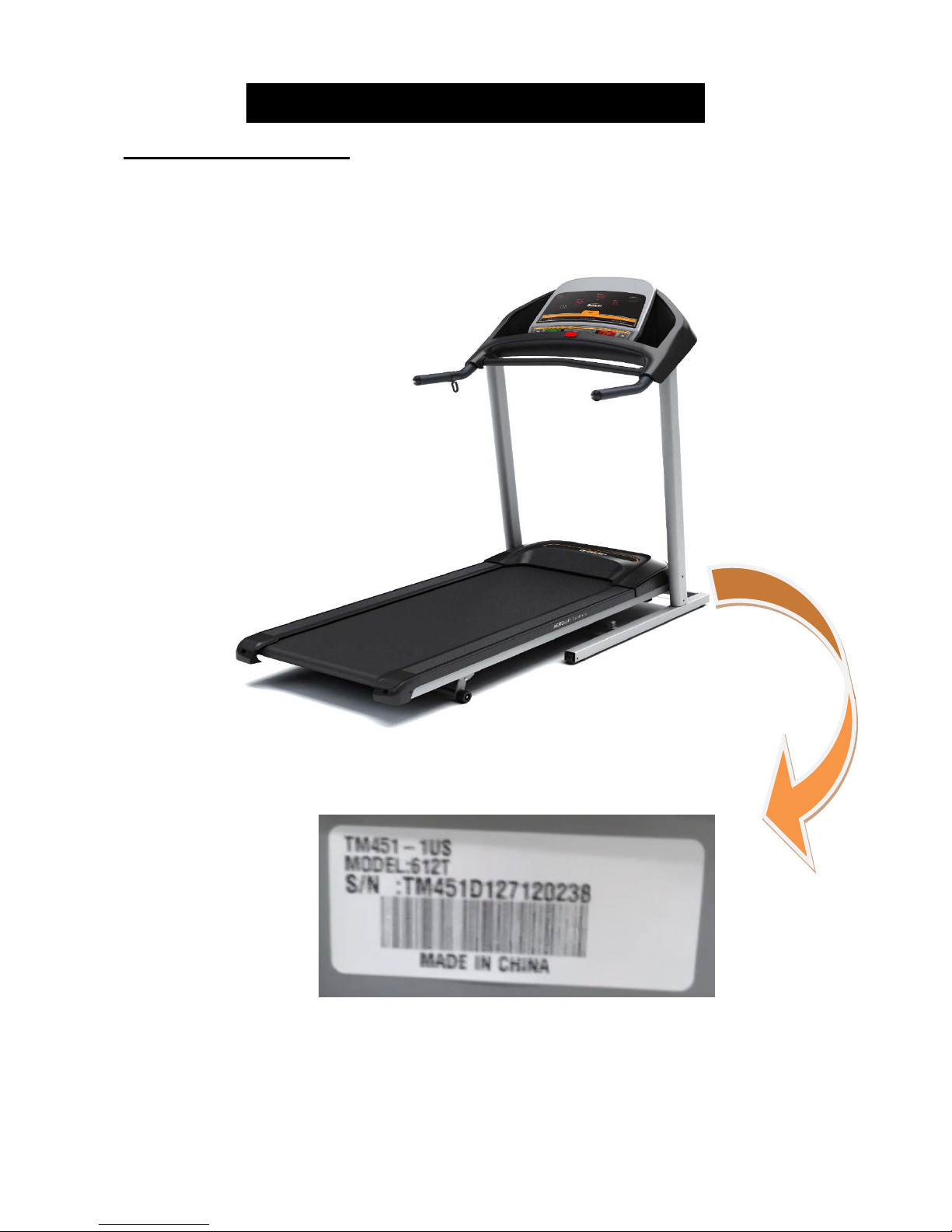
CHAPTER 1: SERIAL NUMBER LOCATION
1.1 Serial Number Location
3
Page 4
CHAPTER 2: ENGINEERING MODE
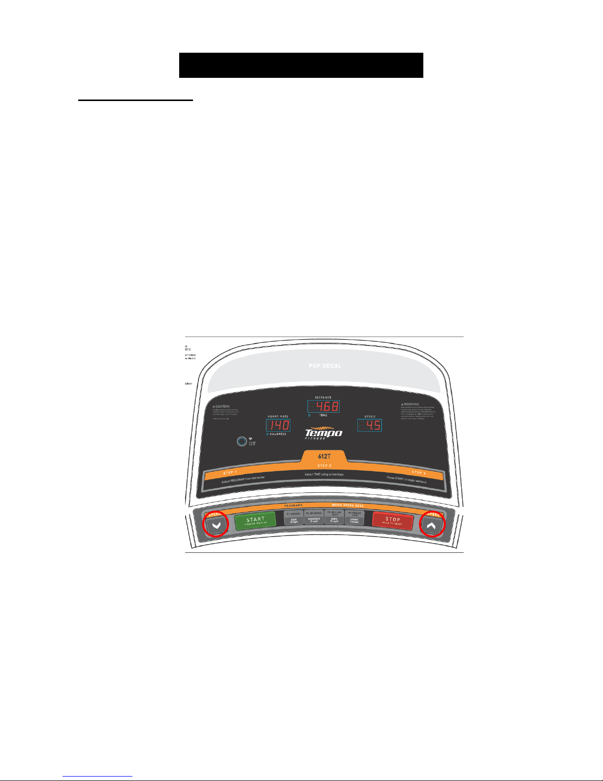
2.1 Engineering Mode
1) To enter Engineering Mode, press & hold the SPEED UP and DOWN keys at the same time for 3-5
seconds until Engineering Menu appears on the display.
2) Use the SPEED UP and DOWN keys to scroll through a list of modes.
3) Press START to enter a mode.
4) Use the SPEED UP and DOWN keys to change the parameter.
5) Press the START key to save the change to the parameter.
6) Press and hold the STOP key to exit Engineering Mode and return to normal operation.
4
Page 5

CHAPTER 2: ENGINEERING MODE
2.2 Engineering Mode – Overview
MODE FUNCTION DESCRIPTION
ENG 0 Display Test Start Key – LCD/LED on
Stop Key – LCD/LED off
Any Other Key - Will show on the display window.
Hold the STOP key for 3 seconds to return to the Engineering Menu.
ENG 1 Hardware Test Motor Test. Press START and the belt should start moving, press
SPEED UP or DOWN to change the speed.
ENG 2 Auto Calibration Auto calibrates the speed only. If the auto calibration passes, the unit
will return to normal operation.
ENG 3 Switch Function Use the START key to select unit (1 = KM & 0 = Mile in the Speed
window).
ENG 4 Information Accumulated Time and Distance
Press the START key to toggle between Time and Distance. Press
and hold the START key for 5 seconds to clear all data.
Unit of Time is Hour & Unit of Distance is KM or Mile based on your
setting.
* Demo Mode – The console will display Figure A after the removal of the safety key; Demo Mode will turn on
60 seconds after the removal of the safety key. The LED and LCD will display in turns in Demo Mode (Figure
B).
FIGURE A FIGURE B
5
Page 6

CHAPTER 3: ELECTRICAL DIAGRAM
3.1 Electrical Diagram
6
Page 7

CHAPTER 4: TROUBLESHOOTING
4.1 Troubleshoo ting – No Power to the Console
Symptom:The power switch is in the on position, but the console will not turn on.
Reason:
1. The outlet is not providing the correct power, or the power cord / switch is defective.
2. The power receptacle or power wiring to the MCB is defective.
3. The MCB is defective.
4. The console cable or console is defective.
Solution:
1. Check to see if there is power to the power switch. If it does not, try a different outlet.
a. If the power switch still does not have power with a known good outlet, replace the power switch.
2. Check to see if the MCB has power. There is a red power LED on the MCB that should be lit.
3. If the MCB does not have power, check the connection of the power wiring from the power
receptacle to the MCB.
a. Use a multi-meter to measure voltage at AC1 & AC2, AC voltage should be the same as local
standard voltage (110V-240V).
b. If the AC voltage value is standard, replace the MCB as it is defective.
7
Page 8

CHAPTER 4: TROUBLESHOOTING
4.1 Troub leshooting – No Power to the Console – Continued
4. If the MCB does have power, check the connection of the console cable wire at the MCB and UCB.
a. Remove the console cable from the MCB, and use a multi-meter to measure the DC voltage
between the “GND pin” (Pins 4 & 5) and the “+ 15V Pin” (Pins 7 & 8). DC output is normally around
15VDC. If there is no output, replace the MCB.
b. If output is around 15VDC, check the console cable for pinches or kinks. If any damage is found,
replace the console cable. Disconnect the console cable at the UCB and measure the DC voltage
between the “GND pin” (Pins 4 & 5) and the “+ 15V Pin” (Pins 7 & 8). DC output is normally around
15VDC. If there is no output, replace the console cable.
c. If there output, replace the UCB.
8
Page 9

CHAPTER 4: TROUBLESHOOTING
4.2 Troubleshooting – Keypads Not Responding
Symptom:
Reason:
1. The keypads are defective.
2. The console is defective.
Solution:
1. Press the SPEED UP and DOWN keys together for 3 seconds to enter Engineering Mode.
2. If any keypads are not chiming during Step 1, check the connection of the keypad ribbon cable at the
UCB.
3. If the keypads do not resolve the issue, replace the UCB.
The keypads are not responding when pressed.
a. Use the SPEED UP or DOWN key to scroll to ENG0, and press START.
b. Test each of the keypads using Display Test. The console should chime as each key is
pressed.
a. Even if the connection appears good, detach the ribbon cable from the UCB, and then
re-attach and retest.
b. Replace the keypads as needed.
9
Page 10

CHAPTER 4: TROUBLESHOOTING
4.3 Troub leshooting – No Console Response
Symptom:
pressed.
Reason:
1. The keypads are defective.
2. The console is defective.
3. The drive motor is defective.
4. The speed sensor is defective.
5. The MCB is defective.
Solution:
1. Check if the console beeps when all keys are pressed. If not, troubleshoot the keypads as outlined in
Section 4.2.
2. Enter Engineering Mode (See Section 2.1), and scroll to ENG 1 (Hardware Test). Press the START
key.
a. Press the SPEED UP and DOWN keys, if the data in windows TIME and DISTANCE changes, the
3. Turn off the power switch, and open the upper motor cover. Remove the red & black wires coming
from the motor to the MCB, and use a multi-meter to measure the resistance of the drive motor wire.
a. If the resistance is higher than 10 Ω, the drive motor is defective. Replace the drive motor.
b. If the resistance is lower than 10 Ω, the drive motor is ok.
4. Check the connection of the speed sensor (encoder disk group) at the MCB (Figure A).
a. Remove the speed sensor from the motor and clean it (Figure B), then re-test.
b. If the speed sensor is clean and has a good connection but still will not operate, replace the speed
sensor.
5. Replace the MCB as the last step if the unit still does not run after taking the above actions.
The power is on and the console lights up, but the treadmill does not run when keys are
console is ok. If the data does not change, replace the UCB.
FIGURE A FIGURE B
10
Page 11

CHAPTER 4: TROUBLESHOOTING
4.4 Troubleshooting – Speed Feedback Inaccurate
Symptom:
Reason:
1. The treadmill needs to be calibrated.
2. The speed sensor is defective.
3. The MCB is defective.
Solution:
1. Enter Engineering Mode (See Section 4.1), and scroll to ENG 2 (Auto Calibrate). Press the START
key (Figure A). The treadmill running belt will begin to move automatically from speed level P0 to P4.
P1 – speed range of 0-1 MPH P2 – speed range of 1-2.7 MPH P3 – speed range of 2.7-6.5 MPH
P4 – speed range of 6.5-8.9 MPH P2 – speed range of 8.9-10 MPH
a. Upon successful calibration, the treadmill will beep several times. The console will automatically
exit Engineering Mode and return to the start-up screen.
b. If Auto Calibration can be completed successfully, the issue will normally be fixed.
c. If an “E1” error is presented on the console during auto-calibration (Figure B), check the connection of
the speed sensor wire from the front roller to the MCB (Figures C & D). Replace the speed sensor
wire if needed.
The treadmill speed shown on the display is higher or lower than the actual speed.
FIGURE A FIGURE B
FIGURE C FIGURE D
2. If auto calibration can be still not performed, replace the MCB as the last step.
11
Page 12

CHAPTER 4: TROUBLESHOOTING
4.5 Troubleshoo ting – Noi se Issues
Symptom:
1. Thumping noise twice per rotation on a new machine.
2. Rubbing / grinding noise.
3. High pitched “bell-like” sound from under the motor cover.
4. Banging or clunking sound.
5. Slapping / thunking / squeaking sound with each footstep.
6. Rubbing sound underneath the treadmill.
Reason:
1. Roller or belt noise.
2. Moving component is rubbing.
3. Optic disk rubbing.
4. The unit is not level.
5. Running deck or belt system is not tight.
6. The running belt is rubbing on something.
Solution:
1. This noise is typically from the roller or running belt.
a. If this is a new unit, some noise is normal as the running belt forms around the rollers.
b. Check that the belt is centered and tensioned correctly.
c. Remove and clean the rollers if needed.
d. Replace the rollers or running belt as needed.
2. This sound is likely a moving component.
a. Remove the motor cover and check the drive belt for alignment and make sure it is not slipping or
is frayed / cut in any way. Replace the drive belt if needed.
b. Make sure the optic disk on the motor is not rubbing the speed sensor.
c. Turn the motor by hand to see if motor brushes or bearings are rubbing. Replace the motor
if needed.
d. Check the front and rear rollers, replace if needed.
3. This sound is likely caused by the optic disk.
a. Check that the optic disk is tight on the motor and not rubbing the speed sensor.
12
Page 13

CHAPTER 4: TROUBLESHOOTING
4.5 Troubleshoo ting – Noi se Issues - Continued
4. The sound is likely due to the unit not being level.
a. Check that all levelers are touching the ground.
b. Move the treadmill to another flat surface.
5. This sound is likely from the running deck / belt.
a. Check that the running deck is tightly attached to the frame.
b. Check the deck shocks for deterioration or crumbling. Replace if needed.
c. Check to see if the air shock is making this noise, lubricate or replace if needed.
6. This sound is likely due to the belt rubbing on something.
a. Make sure the belt is not rubbing on the deck, side rails, or deck shocks.
b. Check that the running belt is tensioned correctly.
C
13
 Loading...