

Horizon 24VF Installation Operation & Maintenance

Installation
Horizon
Operation &
Maintenance
24VF
Vent Free
Gas Fireplace
Adjustable from
14,000 BTU/H to
18,000 BTU/H
Check local codes and read all
instructions prior to installation.
Installer: Leave this manual
with the appliance.
Consumer: Leave this man-
ual for future reference.
WARNING:
If the information in this manual
is not following exactly, a re or
explosion may result causing
property damage, personal injury,
or loss of life.
What To Do If You Smell Gas:
• DO NOT try to light any appliance.
• DO NOT touch any electrical switch; DO NOT use any phone in your
building.
• Immediately call your gas supplier from a neighbor's phone. Follow the
gas supplier's instructions.
• If you cannot reach your gas supplier, call the re department.
Installation and service must be performed by
a qualified installer, service agency, or the gas
supplier.
F O R Y O U R
SAFETY:
Do not store or use gasoline
or other ammable vapors
and liquids in the vicinity of
this or any other appliance.
This is an unvented
gas-fired heater. It
uses air (oxygen) from
the room in which it
is installed. Provisions
for adequate combustion and ventilation
air must be provided.
Refer to page 3.
359
24VF Gas Fireplace
Horizon
Table Of Contents
Introduction .............................................................................. 2
Installation
Installing the Fireplace Shell .......................................... 2
Vent Free Installation ..................................................... 3
Installing the Gasline ...................................................... 4
Construction around the replace
Facing ................................................................ 5
Mantels and Surrounds ..................................... 5
Removing and Installing the Screen Door...................... 6
Installing the Logset ....................................................... 6
Safety Considerations ............................................................. 7
Operation .................................................................................. 8
Maintenance ........................................................................ 9-10
Troubleshooting Guide ......................................................... 11
Warranty ................................................................................. 12
Introduction
Thank You for choosing a Montigo C-Series Fireplace.
About the 24VF Fireplace:
The 24VF includes an adjustible burner from 18,000 BTU/H to 14,000
BTU/H and a 2 piece ceramic bre logset. The 24VF is rated for
Propane with a maximum input of 18,000 BTU/H and a minimum
input of 14,000 BTU/H.
Important Warranty and Installation Information:
The Montigo warranty will be voided by, and Montigo disclaims any
responsibility for, the following actions:
Modication of the replace and/or components including the
rebox door.
Use of any component part not manufactured or approved by
Montigo in combination with this Montigo replace system.
Installation other than as instructed in this manual.
Consult your local Gas Inspection Branch on installation requirements
for factory-built gas replaces. Installation & repairs should be done
by a qualied contractor.
Installation
CAUTIONS
Due to its high operating temperatures, the appliance
should be located out of trafc & away from furniture and
draperies.
Children and adults should be alerted to the hazards of
the high surface temperature, which could cause burns
or clothing ignition.
Young children should be carefully supervised when they
are in the same room as the appliance.
Clothing or other ammable materials should not be
placed on or near the appliance.
Any safety screen or guard removed for servicing an ap-
pliance must be replaced prior to operating the heater.
Installation and repair should be done by a qualied service
person. The appliance should be inspected before use
and at least annually by a professional service person.
More frequent cleaning may be required due to excessive
lint from carpeting, bedding material, etc. It is imperative
that control compartments, burners and air-circulating
Choosing a Location
The replace may be installed in a location that maintains proper
clearances to air conditioning ducts, electrical wiring and plumbing.
Safety, as well as efciency of operation, must be considered when
selecting the replace location. Try to select a location that does not
interfere with room trafc and has adequate ventilation. This re-
place cannot be installed in a high rise at, in a bedroom or in a
bathroom.
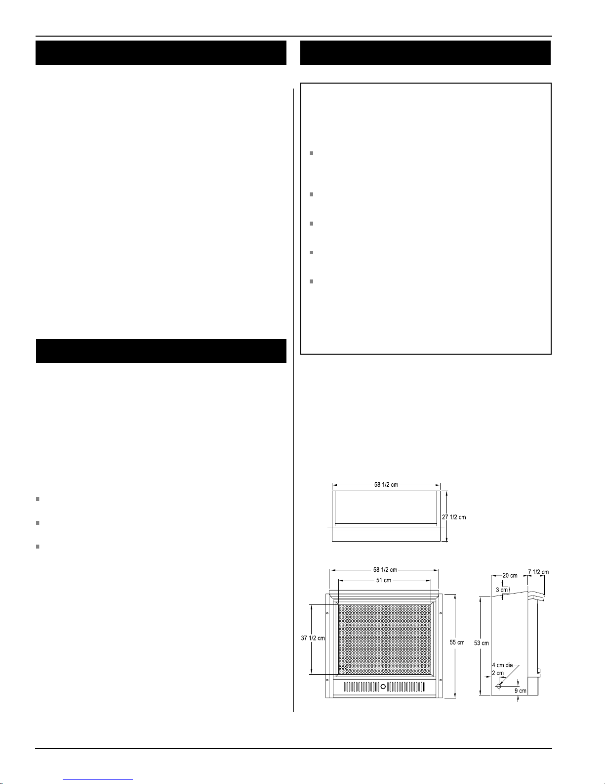
Top Veiw
Page 2
Figure 1.
Front View Side View
Fireplace dimensions.
Part No. XG0138
Horizon
Installation
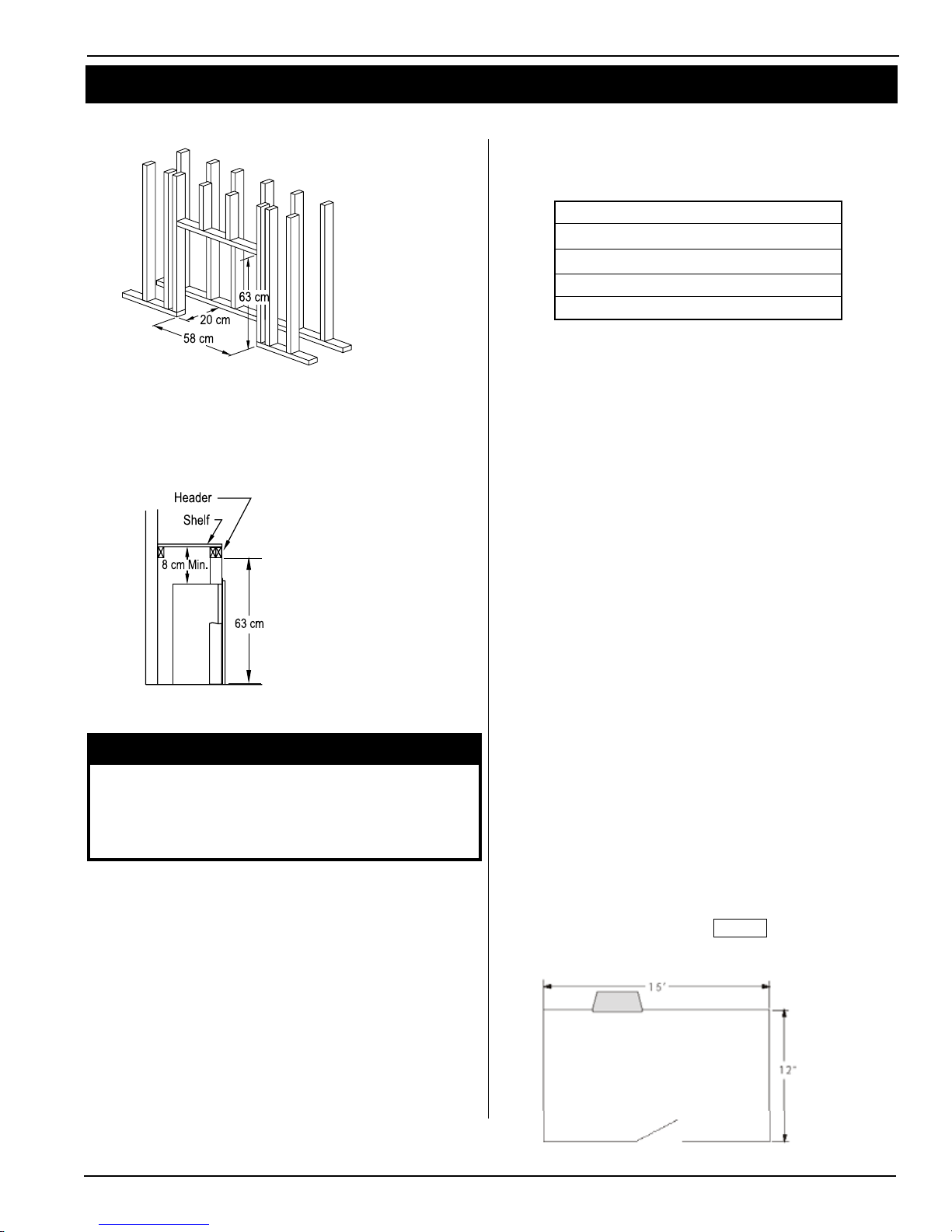
Framing
* When sheetrock is
not used behind the
fireplace, framing
depth may be reduced
to 18 cm
Figure 2. Framing dimensions.
When installing a shelf over the top of the replace, the following
guidelines must be adhered to: The minimum clearance from the top
of the replace to a shelf is 8 cm.
24VF Gas Fireplace
Clearances
These clearances apply to all dimensions except the framed opening,
where the clearance to combustibles is 0 cm. The 24VF clearances to
combustible materials are:
Top 8 cm
Back 0 cm
Sides 0 cm
Floor 0 cm
Mantle** 31 cm
* Clearance from the top of the replace to a combusti-
ble ceiling within the replace enclosure.
** Refer to page 5.
Unprotected combustible walls which are perpendicular to the replace opening, must fall within the limits outlined in Figure 7.
For protection against freezing temperatures, it is recommended that
outer walls of the chase be insulated with a vapour barrier. This will
reduce the possibility of a cold-air convection current on the replace.
Figure 3. Framing for shelves over the fireplace.
WARNING:
When this appliance is installed directly on carpeting, tile or
any combustible material other than wood ooring, it must
be installed on a metal or wood panel extending the full
width and depth of the appliance.
Space Requirements
This heater must not be installed in a conned space or unusually
tight construction unless provisions are made for adequate combustion and ventilation air.
The National Fuel Gas Code, ANSI Z223.1, denes a conned space
as a space whose volume is less than 50 cubic feet per 1,000 BTU
per hour (4.8 m3 per kw) of the aggregate input rating of all appliances
installed in that space and an unconned space as a space whose
volume is not less than 50 cubic feet per 1,000 BTU per hour (4.8 m3
per kw) of the aggregate input rating of all appliances installed in that
space. Rooms communicating directly with the space in which all the
appliances are installed, through openings not furnished with doors,
are considered a part of the unconned space.
Example:
If you are installing this replace in a rectangular room which measures 12' × 15' × 8' in height, that room will have a volume of 1440 cu.
ft. (ft3). If there is no other appliances in the room which consume
oxygen, then the maximum BTU replace which can be installed in
such a room is 28,800 BTU (1440 ft3 ÷ 50 × 1000) The minimum
volume of space in which this replace can be installed is equal
to:
18,000 BTU's / hour ÷ 1000 = 18 kBTU/h
18 kBTU/h × 50 ft3 / kBTU/h = 900 ft
Therefore this heater may be installed in the space
3
Part No. XG0138
Figure 4. Dimensions of the room example.
Page 3
24VF Gas Fireplace
Horizon
Installation
WARNING:
If the area in which the heater may be operated is smaller
than that dened as an unconned space, or if the building
is one of unusually tight construction, provide adequate
combustion air by one of the methods described in applicable local codes.
Unusually tight construction is dened as construction where:
Walls and ceilings exposed to the outside atmosphere have a
continuous water vapour retarder with a rating of 1 perm ( 6x 10
kg per pa-sec-m2) or less with openings gasketed or sealed, and
Weather Stripping has been added on openable windows and
doors, and
Caulking or sealants are applied to areas such as joints around
window doors and frames, between sole plates and oors, between wall-ceiling joints, between wall panels, at penetrations for
plumbing, electrical and gas lines, and at other openings.
WARNING:
Do not allow fans to blow directly into the replace. Avoid
any drafts that alter burner ame patterns.
Keep appliance area clear and free from combustion materials, gasoline and other ammable vapors and liquids.
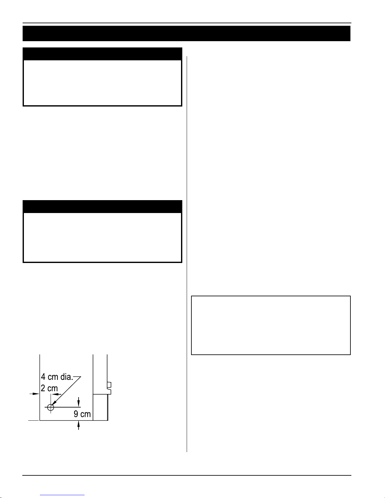
Installing The Gas Line
1. The gas line must be installed before nishing the 24VF Fireplace.
Propane Gas requires a minimum inlet gas supply pressure of 35
mbar W.C. & a manifold pressure of 24 mbar Provision must also
be made for a 1/8" N.P.T. plugged tapping and be accessible for test
gauge connection immediately upstream of the gas supply controls to
the appliance. The replace gas connection and the main operating
gas valve is located behind the removable brass trim at the bottom of
the unit and need only be attached to the gas line with an approved
tting, as required by the applicable installation codes.
2. The appliance and its individual shutoff valve must be disconnected
from the gas supply piping system during any pressure testing of that
system at test pressures in excess of 3.5 kPa.
3. The appliance must be isolated from the gas supply piping system
by closing its individual manual shutoff valve during any pressure
testing of the gas supply piping system at test pressures equal to or
less than 3.5 mbar.
4. Determine that the gas pressure does not exceed 3.5 mbar and/or
check the corresponding minimum inlet ratings. Once the gas ratings
are determined adequate and the system does not leak, then connect
-11
the gas appliance and retest gas pressure for a total system leakage
by meter measuring at the gas valve pressure measuring port. If leaks
are determined, then repair and repeat the pressure test procedure.
5. Turn main gas control pilot knob OFF during any pressure testing.
Test pressure should be equal to or less than 3.5 kPa to prevent damage to control valve.
6. Installation requirements and combustion and ventilation air provisions must conform with local codes.
7.Keep the operating area clear and free of: combustible materials,
gasoline, or any vapours that would be ammable.
8. Never install a replace in a bathroom, recreational vehicle, high
trafc areas, windy or draft areas, or where ammable objects, such
as curtains, furniture or clothing, are less than 1 meter from the front
of the replace.
9. Due to high temperatures, the appliance should be located out
of trafc and away from furniture and draperies.
10. Children and adults should be alerted to the hazard of high
surface temperatures and should stay away to avoid burns or
Note: After gas line is connected, each appliance connection,
valve and valve train must be checked while under normal
operating pressure with either a liquid solution, or leak
detection device, to locate any source of leak. Tighten
any areas where bubbling appears or leak is detected until
bubbling stops completely or leak is no longer detected.
DO NOT use a flame of any kind to test for leaks.
Figure 5. Gas line access.
Page 4
Part No. XG0138
Horizon
Installation
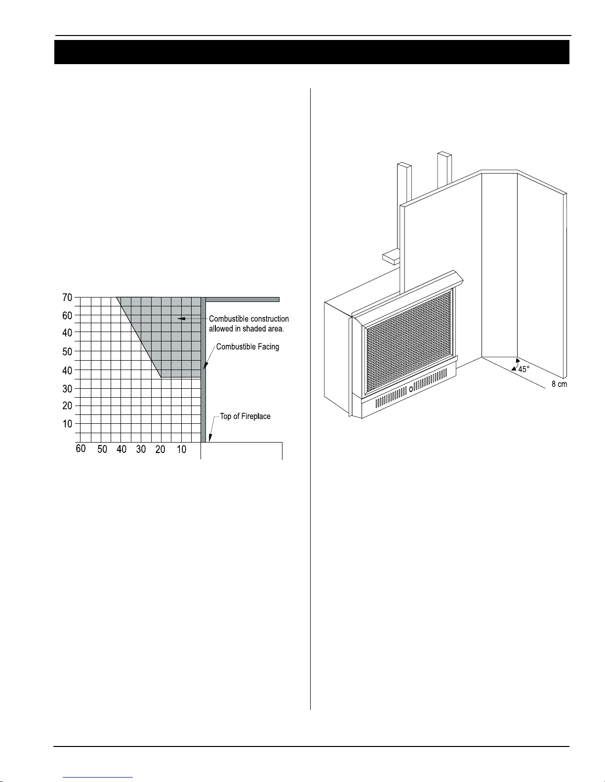
Finishing Around the Fireplace
Combustible mantels and mouldings may be safely installed over the
top and on the front of the replace provided that they do not project
beyond shaded area shown in Figure 6. Side wall clearances are 8
cm. Combustible surrounds may be installed with an 8cm clearance to
the side of the replace as shown in Figure 7.
Fireplace Facing
When selecting the nish material for your replace, it is important
to remember the following: THE BOTTOM GRILL MUST NOT BE
OBSTRUCTED IN ANY WAY - to do so restricts the air supply for
the control compartments and it also prevents access for servicing controls.
The face of the replace may be painted to match the room decor,
provided you use a heat-resistant paint. Decorative facing must not
extend past the replace opening at all, because it will interfere with
the access to retainers for removal of screen door.
24VF Gas Fireplace
Association, when painting the replace surrounds, to select and apply a quality Alkyd sealer prior to the applying of latex paints. This is
to prevent leaching of water from evaporation and causing a brownish
staining effect to paint over coats.
Figure 6. Combustible mantles and facings (measurements in cm).
Mantels & Surrounds
New technology, to meet consumer and government demands for the
wise use of energy, has prompted us to manufacture many models of
replaces which are hot, fuel and energy efcient.
Please be aware; temperatures over the mantel will rise above normal room temperature and walls above replace may be hot to touch.
We recommend careful consideration be given to the effects of
elevated mantel temperatures which may be in excess of product
design, for example: candles, plastic or pictures. This can cause
melting, deformation, discoloration or premature failure of T.V. and
radio components.
Painting:
Figure 7. Combustible surrounds.
Part No. XG0138
Page 5
 Loading...