

Horiba U-50 Operating Manual

Multi Water Quality Checker
U-50 Series
Instruction Manual
CODE:GZ0000144342C

Preface
This manual describes the operation of the Multi Water Quality Checker, U-50 Series.
Be sure to read this manual before using the product to ensure proper and safe operation of
the instrument. Also safely store the manual so it is readily available whenever necessary.
Product specifications and appearance, as well as the contents of this manual are subject to
change without notice.
■ Warranty and Responsibility
HORIBA warrants that the Product shall be free from defects in material and workmanship
and agrees to repair or replace free of charge, at HORIBA’s option, any malfunctioned or
damaged Product attributable to HORIBA’s responsibility for a period of one (1) year from the
delivery unless otherwise agreed with a written agreement. In any one of the following cases,
none of the warranties set forth herein shall be extended;
z
Any malfunction or damage attributable to improper operation
z
Any malfunction attributable to repair or modification by any person not authorized by
HORIBA
z
Any malfunction or damage attributable to the use in an environment not specified in this
manual
z
Any malfunction or damage attributable to violation of the instructions in this manual or
operations in the manner not specified in this manual
z
Any malfunction or damage attributable to any cause or causes beyond the reasonable
control of HORIBA such as natural disasters
z
Any deterioration in appearance attributable to corrosion, rust, and so on
z
Replacement of consumables
HORIBA SHALL NOT BE LIABLE FOR ANY DAMAGES RESULTING FROM ANY
MALFUNCTIONS OF THE PRODUCT, ANY ERASURE OF DATA, OR ANY OTHER USES
OF THE PRODUCT.
■ Trademarks
Generally, company names and brand names are either registered trademarks or trademarks
of the respective companies.
April, 2009 © 2008 − 2009 HORIBA, Ltd.
Conformable Directive
This equipment conforms to the following directives and standards:
Directives:
Standards:
the EMC Directive 2004/108/EC
[the EMC Directive]
EN61326-1:2006 Class B, Portable test and measurement
equipment
J Information on Disposal of Electrical and Electronic Equipment
and Disposal of Batteries and Accumulators
The crossed out wheeled bin symbol with underbar shown on the product or accompanying
documents indicates the product requires appropriate treatment, collection and recycle for
waste electrical and electronic equipment (WEEE) under the Directive 2002/96/EC, and/or
waste batteries and accumulators under the Directive 2006/66/EC in the European Union.
The symbol might be put with one of the chemical symbols below. In this case, it satisfies the
requirements of the Directive 2006/66/EC for the object chemical.
This product should not be disposed of as unsorted household waste.
Your correct disposal of WEEE, waste batteries and accumulators will contribute to reducing
wasteful consumption of natural resources, and protecting human health and the environment
from potential negative effects caused by hazardous substance in products.
Contact your supplier for information on applicable disposal methods.
FCC Rules
Any changes or modifications not expressly approved by the party responsible for compliance
shall void the user's authority to operate the equipment.
■ WARNING
This equipment has been tested and found to comply with the limits for a Class A digital
device, pursuant to part 15 of the FCC Rules. These limits are designed to provide reasonable
protection against harmful interference when the equipment is operated in a commercial
environment. This equipment generates, uses, and can radiate radio frequency energy and, if
not installed and used in accordance with the instruction manual, may cause harmful
interference to radio communications.
Operation of this equipment in a residential area is likely to cause harmful interference in
which case the user will be required to correct the interference at his own expense.

For your safety
Warning messages are described in the following manner. Read the messages and follow the
instructions carefully.
● Meaning of warning messages
This indicates an imminently hazardous situation which, if not avoided, will
result in death or serious injury. This signal word is to be limited to the most
extreme situations.
This indicates a potentially hazardous situation which, if not avoided, could
result in death or serious injury.
This indicates a potentially hazardous situation which, if not avoided, may
result in minor or moderate injury. It may also be used to alert against
unsafe practices.
Without safety alert indication of hazardous situation which, if not avoided,
could result in property damage.
● Symbols
Description of what should be done, or what should be followed
Description of what should never be done, or what is prohibited
■ Safety Precautions
This section provides precautions to enable you to use the product safely and correctly and to
prevent injury and damage. The terms of DANGER, WARNING, and CAUTION indicate the
degree of imminency and hazardous situation. Read the precautions carefully as it contains
important safety messages.
WARNING
Do not disassemble or modify the meter.
May cause overheating or fire, resulting in accidents.
CAUTION
The pH and ORP sensors are made of glass. Handle them carefully to avoid breakage.
Do not ingest the DO, pH or ORP standard solutions.
If it comes into contact with the eyes, rinse thoroughly with water. If swallowed, consult a physician.
Keep away from water when using USB communication. Improper use may result in fire or damage.
Points of concern
Use of the equipment in a manner not specified by the manufacturer may impair the protection
provided by the equipment. It may also reduce equipment performance.
Q Sensor probe
z
Do not immerse the sensor probe in seawater or other samples with high salinity. Doing
so may erode metallic parts. After use, promptly wash the sensor probe thoroughly in
water.
z
Do not immerse the sensor probe in alcohol, organic solvent, strong acid, strong alkaline,
and other similar solutions.
z
Do not subject to strong shocks.
z
Do not perform measurement in environments of magnetic fields. Measurement errors
may result.
z
The sensor probe is no longer waterproof when the sensors are not mounted.
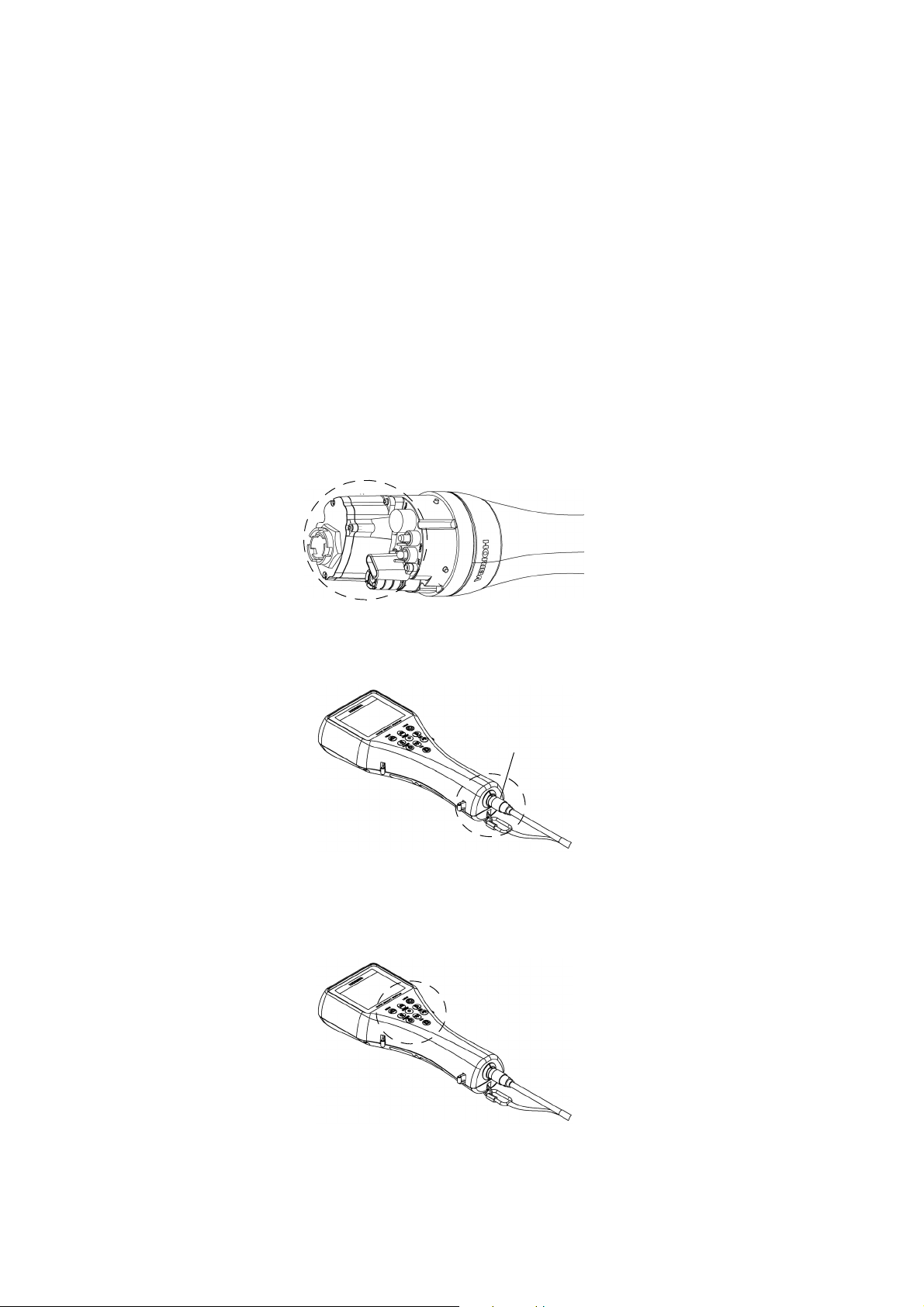
Appearance of mounted sensors
z
Does not support measurement of samples containing fluorine.
z
To disconnect the sensor cable or interface cable, pull them out with holding the
connector part. Do not pull the cable part; it may cause breakage.
Q Control unit
z
Do not subject to strong shocks.
z
The operation keys are designed to operate using the pad of a finger, sharp objects can
tear the control unit cover damaging the operation keys.
Connector part
Operation keys
z
The control unit is no longer waterproof when the USB cable is connected.
z
When operating the control unit only, protect the connector with the connector cap
provided.
z
Remove the batteries when not using the control unit for an extended period of time.
Battery fluid leakage may cause equipment failure.
z
Do not wipe the control unit with organic solvents or powder polish. The surface may
deteriorate or its printing may disappear. If the display becomes dirty, wipe the dirt off with
a soft cloth soaked in neutral detergent.
z
Do not turn the power OFF or disconnect the cable during calibration or setting. Memory
data may be erased.
z
To perform measurement, connect the sensor probe cable before turning the power ON.
z
Do not remove the battery gasket or twist it.
z
When opening the battery case, make sure that no foreign matter is attached to the
battery gasket.
z
Do not use any unspecified batteries; it may cause breakage.
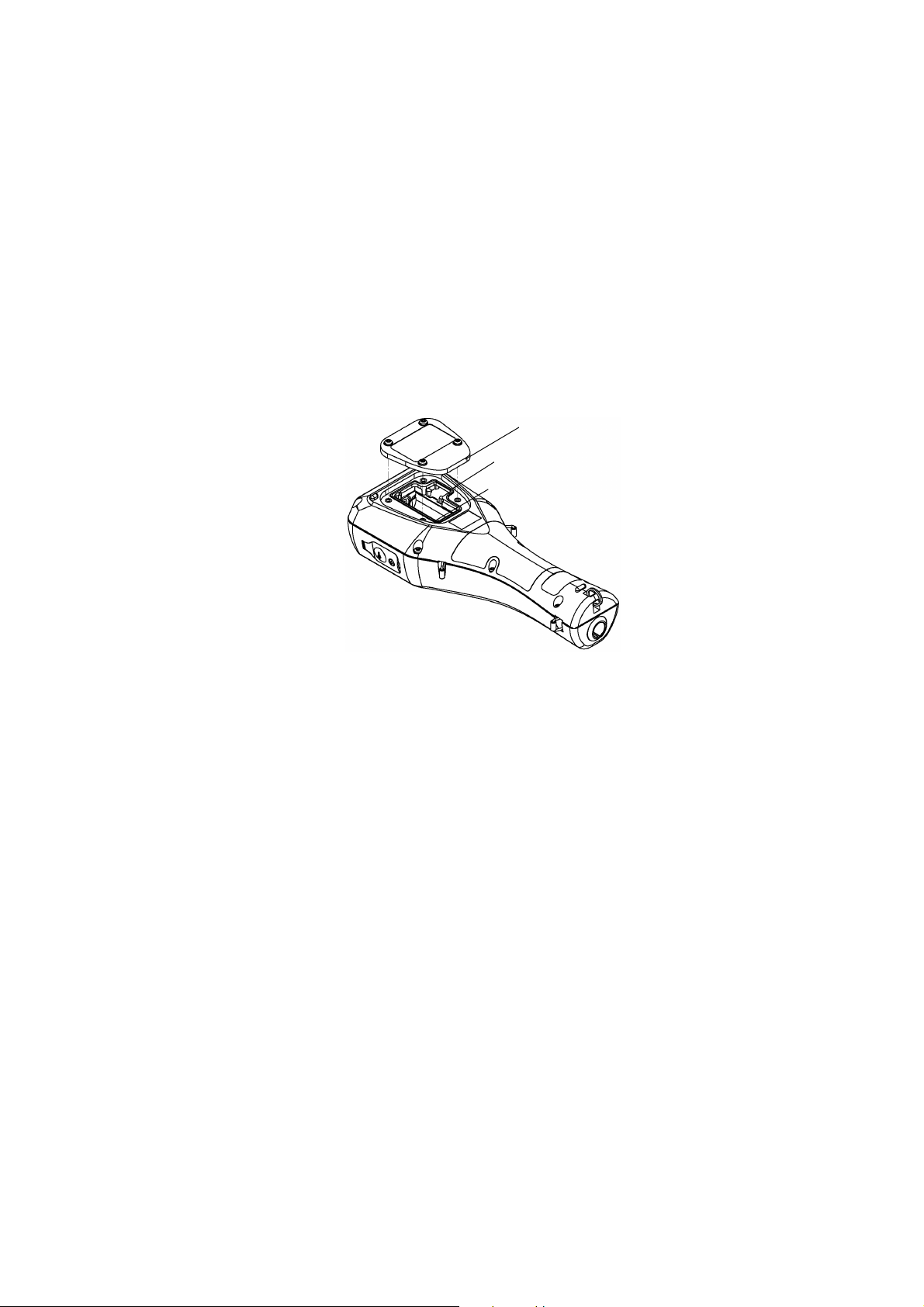
Battery cover
Battery gasket
Batteries
Q Measurement
z
Do not pull the cable when lowering the sensor probe into the sample during
measurement. Lower the sensor probe into the sample on a chain or string.
z
Before lowering the sensor probe into the sample, do not connect the hook on the unit to
a human body.
z
The correct values are not displayed if the sensor is not mounted when the measurement
display is activated.
z
Perform DO measurement with no air bubbles in the internal solution.
z
Do not reuse a membrane cap of DO sensor.
z
Use the spanner for DO sensor provided to attach or remove the DO sensor.
z
Avoid both U-53 and U-53G turbidity measurement in air, since the rubber wiper will
quickly become damaged.
z
Avoid turbidity measurement in direct sunlight, since the readout may be affected.
Q Calibration
During atmosphere calibration for the DO electrode with DO salinity compensation set to
automatic, values are compensated based on electrical conductivity, but calibration is
performed normally.
Location of use and storage
z
Storage temperature: −10°C to 60°C
z
Relative humidity: Under 80% and free from condensation
Store the meter in locations void of dust, strong vibrations, direct sunlight, corrosive gases,
near air conditioners or windy areas.
Disposal of the product
When disposing of the product, follow the related laws and/or regulations of your country for
disposal of the product.
Description in this manual
Note
This interprets the necessary points for correct operation and notifies the important points for
handling the unit.
Reference
This indicates where to refer for information.
Tip
This indicates reference information.

Contents
1 About this Unit . . . . . . . . . . . . . . . . . . . . . . . . . . . . . . . . . . . . 1
2 Device Information. . . . . . . . . . . . . . . . . . . . . . . . . . . . . . . . . 2
2.1 Measurement parameters . . . . . . . . . . . . . . . . . . . . . . . . . . . . . . 2
2.2 Packing list . . . . . . . . . . . . . . . . . . . . . . . . . . . . . . . . . . . . . . . . . . 3
2.3 Parts name and functions . . . . . . . . . . . . . . . . . . . . . . . . . . . . . . . 4
2.4 Setting menu items . . . . . . . . . . . . . . . . . . . . . . . . . . . . . . . . . . . . 7
2.5 Calibration menu items . . . . . . . . . . . . . . . . . . . . . . . . . . . . . . . . . 7
2.6 Data operation menu items . . . . . . . . . . . . . . . . . . . . . . . . . . . . . 7
3 Basic Operation . . . . . . . . . . . . . . . . . . . . . . . . . . . . . . . . . . . 8
3.1 System setup . . . . . . . . . . . . . . . . . . . . . . . . . . . . . . . . . . . . . . . . 8
3.1.1 Inserting and replacing the batteries . . . . . . . . . . . . . . . . . . . . . . . . . 8
3.1.2 Replacing the coin battery . . . . . . . . . . . . . . . . . . . . . . . . . . . . . . . . . 10
3.1.3 Attaching sensors . . . . . . . . . . . . . . . . . . . . . . . . . . . . . . . . . . . . . . . 11
3.1.4 Connecting the control unit and sensor probe . . . . . . . . . . . . . . . . . . 14
3.1.5 Conditioning . . . . . . . . . . . . . . . . . . . . . . . . . . . . . . . . . . . . . . . . . . . . 14
3.1.6 GPS (U-52G, U-53G) . . . . . . . . . . . . . . . . . . . . . . . . . . . . . . . . . . . . 15
3.2 Settings . . . . . . . . . . . . . . . . . . . . . . . . . . . . . . . . . . . . . . . . . . . . . 18
3.2.1 Setting measurement methods . . . . . . . . . . . . . . . . . . . . . . . . . . . . . 18
3.2.2 Setting sites . . . . . . . . . . . . . . . . . . . . . . . . . . . . . . . . . . . . . . . . . . . . 20
3.2.3 Unit for report . . . . . . . . . . . . . . . . . . . . . . . . . . . . . . . . . . . . . . . . . . . 23
3.2.4 Sensor selection . . . . . . . . . . . . . . . . . . . . . . . . . . . . . . . . . . . . . . . . 25
3.2.5 Compensation . . . . . . . . . . . . . . . . . . . . . . . . . . . . . . . . . . . . . . . . . . 26
3.2.6 System settings . . . . . . . . . . . . . . . . . . . . . . . . . . . . . . . . . . . . . . . . . 32
3.3 Calibration . . . . . . . . . . . . . . . . . . . . . . . . . . . . . . . . . . . . . . . . . . 39
3.3.1 Auto calibration . . . . . . . . . . . . . . . . . . . . . . . . . . . . . . . . . . . . . . . . . 39
3.3.2 Manual calibration . . . . . . . . . . . . . . . . . . . . . . . . . . . . . . . . . . . . . . . 42
3.4 Measurement . . . . . . . . . . . . . . . . . . . . . . . . . . . . . . . . . . . . . . . . 61
3.4.1 Storing data in memory manually . . . . . . . . . . . . . . . . . . . . . . . . . . . 61
3.4.2 Automatic, continuous measurement . . . . . . . . . . . . . . . . . . . . . . . . 63
3.5 Data operations . . . . . . . . . . . . . . . . . . . . . . . . . . . . . . . . . . . . . . 64
3.5.1 Displaying data . . . . . . . . . . . . . . . . . . . . . . . . . . . . . . . . . . . . . . . . . 64
3.5.2 Deleting data . . . . . . . . . . . . . . . . . . . . . . . . . . . . . . . . . . . . . . . . . . . 68
3.5.3 Checking the data memory . . . . . . . . . . . . . . . . . . . . . . . . . . . . . . . . 69
3.5.4 Checking the calibration record . . . . . . . . . . . . . . . . . . . . . . . . . . . . . 70
3.5.5 GPS data operations . . . . . . . . . . . . . . . . . . . . . . . . . . . . . . . . . . . . . 71
3.6 Sensor information . . . . . . . . . . . . . . . . . . . . . . . . . . . . . . . . . . . . 72
3.7 USB communication . . . . . . . . . . . . . . . . . . . . . . . . . . . . . . . . . . . 73
3.7.1 Communication settings . . . . . . . . . . . . . . . . . . . . . . . . . . . . . . . . . . 73

3.7.2 Commands . . . . . . . . . . . . . . . . . . . . . . . . . . . . . . . . . . . . . . . . . . . . 74
4 Maintenance. . . . . . . . . . . . . . . . . . . . . . . . . . . . . . . . . . . . . . 82
4.1 Routine care . . . . . . . . . . . . . . . . . . . . . . . . . . . . . . . . . . . . . . . . . 82
4.2 Every 2 months maintenance . . . . . . . . . . . . . . . . . . . . . . . . . . . . 83
4.3 Storage . . . . . . . . . . . . . . . . . . . . . . . . . . . . . . . . . . . . . . . . . . . . . 85
4.4 Replacing the turbidity sensor . . . . . . . . . . . . . . . . . . . . . . . . . . . 86
4.5 Replacing the membrane cap . . . . . . . . . . . . . . . . . . . . . . . . . . . . 87
4.6 Troubleshooting . . . . . . . . . . . . . . . . . . . . . . . . . . . . . . . . . . . . . . 89
4.6.1 Error displays . . . . . . . . . . . . . . . . . . . . . . . . . . . . . . . . . . . . . . . . . . 89
4.6.2 Error displays in sensor information . . . . . . . . . . . . . . . . . . . . . . . . . 94
5 Specifications . . . . . . . . . . . . . . . . . . . . . . . . . . . . . . . . . . . . 95
6 Reference . . . . . . . . . . . . . . . . . . . . . . . . . . . . . . . . . . . . . . . . 98
6.1 Consumable parts . . . . . . . . . . . . . . . . . . . . . . . . . . . . . . . . . . . . . 98
6.2 Options sold separately . . . . . . . . . . . . . . . . . . . . . . . . . . . . . . . . 99
6.3 pH measurement . . . . . . . . . . . . . . . . . . . . . . . . . . . . . . . . . . . . . 100
6.3.1 Principle of pH measurement . . . . . . . . . . . . . . . . . . . . . . . . . . . . . . 100
6.3.2 Temperature compensation . . . . . . . . . . . . . . . . . . . . . . . . . . . . . . . 100
6.3.3 Standard solutions . . . . . . . . . . . . . . . . . . . . . . . . . . . . . . . . . . . . . . 100
6.4 DO measurement . . . . . . . . . . . . . . . . . . . . . . . . . . . . . . . . . . . . . 101
6.4.1 Principle of DO measurement . . . . . . . . . . . . . . . . . . . . . . . . . . . . . . 101
6.4.2 Salinity calibration . . . . . . . . . . . . . . . . . . . . . . . . . . . . . . . . . . . . . . . 102
6.5 Conductivity (COND) measurement . . . . . . . . . . . . . . . . . . . . . . . 103
6.5.1 Four-AC-electrode method . . . . . . . . . . . . . . . . . . . . . . . . . . . . . . . . 103
6.5.2 SI units . . . . . . . . . . . . . . . . . . . . . . . . . . . . . . . . . . . . . . . . . . . . . . . 104
6.5.3 Temperature coefficient . . . . . . . . . . . . . . . . . . . . . . . . . . . . . . . . . . 104
6.6 Salinity (SAL) conversion . . . . . . . . . . . . . . . . . . . . . . . . . . . . . . . 106
6.7 TDS conversion . . . . . . . . . . . . . . . . . . . . . . . . . . . . . . . . . . . . . . 106
6.8 σt conversion . . . . . . . . . . . . . . . . . . . . . . . . . . . . . . . . . . . . . . . . 106
6.9 Turbidity (TURB) measurement . . . . . . . . . . . . . . . . . . . . . . . . . . 107
6.9.1 Principle of turbidity measurement . . . . . . . . . . . . . . . . . . . . . . . . . . 107
6.9.2 Standard solution . . . . . . . . . . . . . . . . . . . . . . . . . . . . . . . . . . . . . . . 107
6.10 Depth (DEPTH) measurement . . . . . . . . . . . . . . . . . . . . . . . . . . . 107
6.10.1 Principle of depth measurement . . . . . . . . . . . . . . . . . . . . . . . . . . . . 107
6.10.2 Influence of temperature and calibration . . . . . . . . . . . . . . . . . . . . . 107

6.11 Oxidation reduction potential (ORP) measurement . . . . . . . . . . . 108
6.11.1 Principle of ORP measurement . . . . . . . . . . . . . . . . . . . . . . . . . . . . . 108
6.11.2 Standard electrode (reference electrode) types and ORP . . . . . . . . 108


1 About this Unit
The U-50 Series Multi Water Quality Checker features an integrated control unit and sensors.
It is capable of making a maximum of eleven simultaneous measurements for various
parameters, and is perfect for use in the field. The U-50 Series is designed with on-site easeof-use in mind, provides a wide variety of functions, and can be used for water quality
measurements and inspections of river water, groundwater, and waste water.
1 About this Unit
1
2 Device Information
2 Device Information
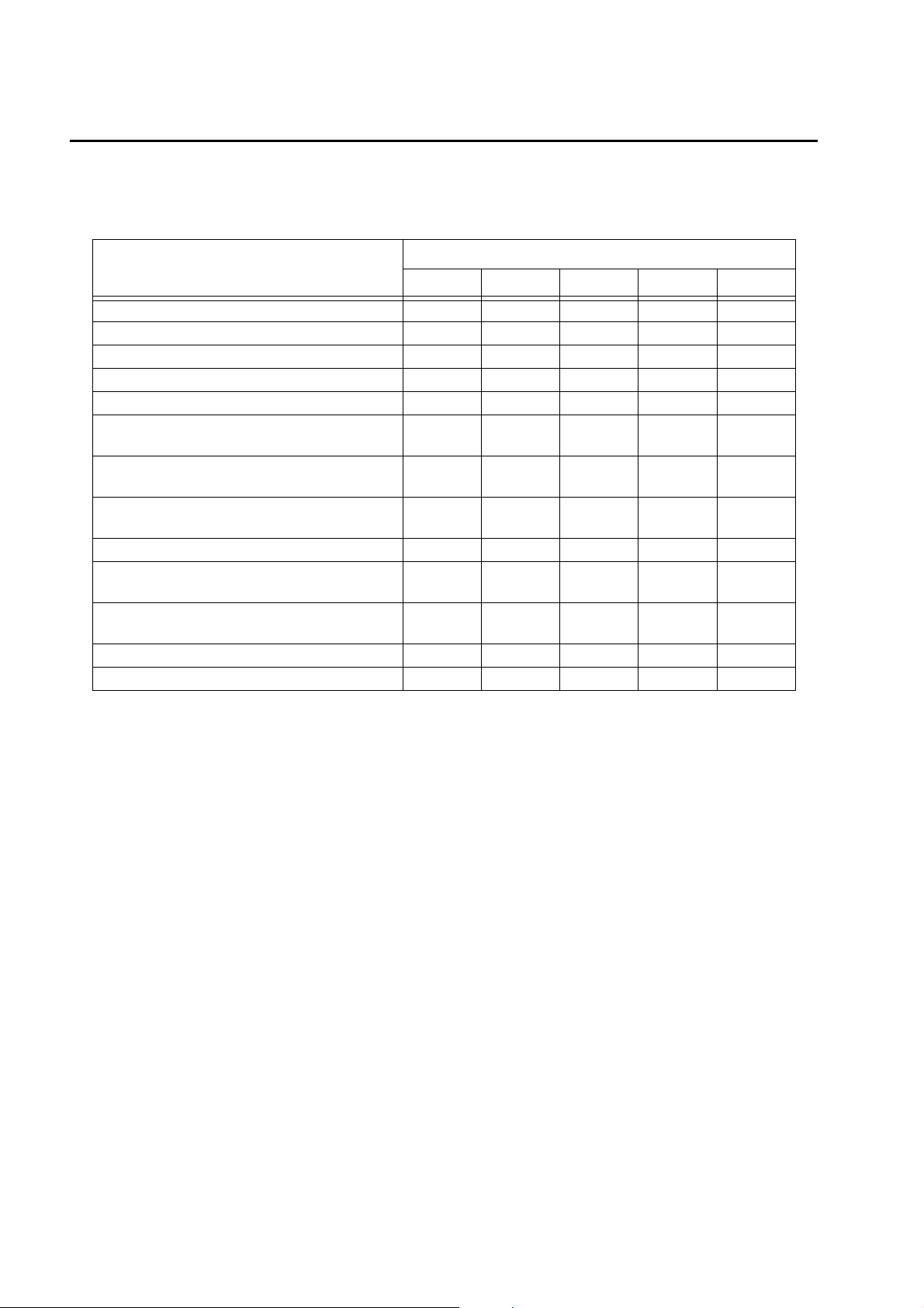
2.1 Measurement parameters
Parameters
pH (pH) 33333
pH (mV) 33333
Oxidation reduction potential (ORP) 33333
Dissolved oxygen (DO) 33333
Electrical conductivity (COND) 33333
Salinity (SAL) [expressed as electrical
conductivity]
Total dissolved solids (TDS) [expressed
as electrical conductivity]
Seawater specific gravity (SG)
[expressed as electrical conductivity]
Water temperature (TEMP) 33333
Turbidity (TURB) [LED transmission/front 30°
scattering method]
Turbidity (TURB) [tungsten lamp 90°
transmission/scattering method] with wiper
Water depth (DEP) −−333
GPS −−3 − 3
U-51 U-52 U-52G U-53 U-53G
33333
33333
33333
− 33 −−
−−−33
Model
"3" indicates a measurable parameter.
2
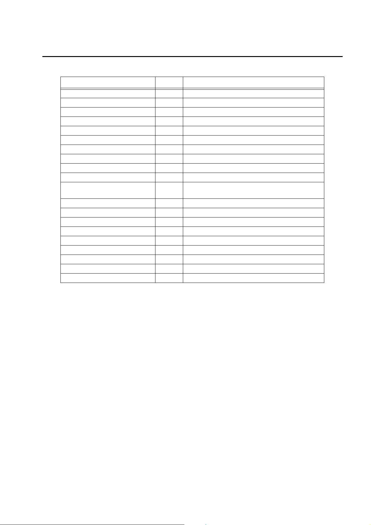
2.2 Packing list
Parts Name Quantity Note
Control unit 1
Sensor probe 1
pH sensor (#7112) 1
ORP sensor (#7313) 1
Reference electrode (#7210) 1
DO sensor (#7543) 1
Turbidity sensor (#7800) 1 With U-52/U-52G only. Attached to the sensor probe.
Turbidity sensor (#7801) 1 With U-53/U-53G only. Attached to the sensor probe.
pH 4 standard solution (#100-4) 1 500 mL
pH reference internal solution (#330) 1 250 mL
DO sensor internal solution set
(#306)
DO Membrane spare parts set 1
Spanner for DO sensor 1
Cleaning brush 1
calibration cup 1 transparent calibration cup, black calibration cup
Back pack 1
Strap 1
Alkaline batteries 4 LR14
Silicon grease 1
Instruction manual 1
Internal solution (50 mL), Sandpaper (#8000, #600),
1
Syringe
2 Device Information
3
2 Device Information
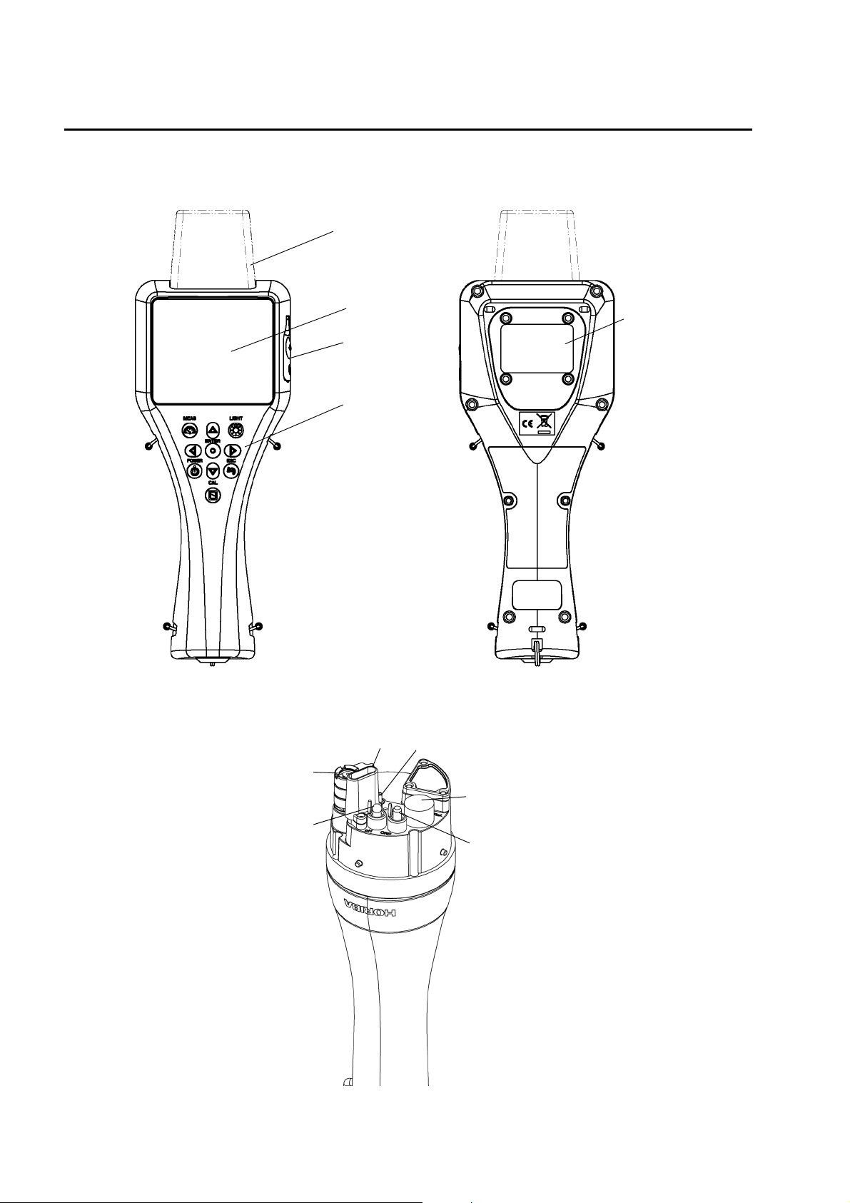
2.3 Parts name and functions
Q Display
GPS unit
(U-52G, U-53G)
Front view Back view
Q Sensor probe (U-51)
Display screen
USB connector
Operation key
Battery cover
DO sensor
pH sensor
COND sensor
Temp. sensor
Reference electrode
ORP sensor
4
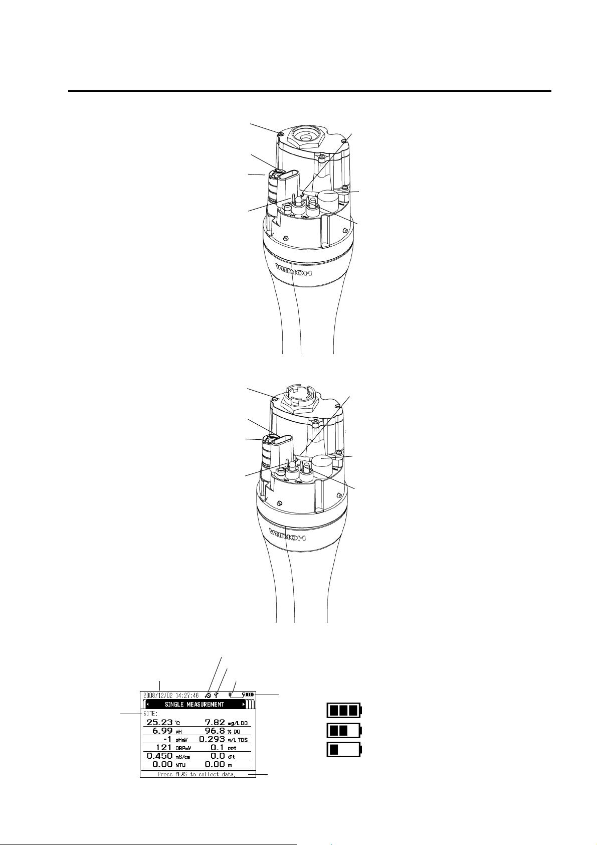
Q Sensor probe (U-52)
2 Device Information
TURB sensor
COND sensor
DO sensor
pH sensor
Q Sensor probe (U-53)
TURB sensor
Temp. sensor
Reference electrode
ORP sensor
Temp. sensor
Q Display screen
YYYY/MM/DD Time
Site name
COND sensor
DO sensor
pH sensor
GPS reception
USB connection status
Reference electrode
ORP sensor
Sensor probe connection status
Battery level
Level 3
Level 2
Sufficient power remaining
Remaining power does not affect operation
Level 1
Operation guidance
Batteries need replacing
5

2 Device Information
Q Operation key
Key name description
POWER key
MEAS key
Turns the system’s power ON/OFF. The initial screen appears
immediately after turning the power ON.
Press and hold down the POWER key for about 3 seconds to turn
the power ON and OFF.
When pressed in the measurement screen, used to set the
measurement values of all the measurement parameters.
Measurement values flash until the data stabilizes.
When pressed in the setting, calibration or data operation screen,
returns to the measurement screen.
ENTER key
CAL key Switches to the calibration screen.
ESC key Returns to the immediately preceding operation.
LIGHT key
Left key Moves the cursor to the left.
Used to execute functions, set entered values or store data in
memory.
Turns the backlight ON/OFF.
z
Using the backlight shortens battery life.
z
The backlight does not light for about 3 seconds after power
ON.
z
When the sensor probe is connected while the display's
backlight is lit, the backlight goes out for about 3 seconds.
Right key Moves the cursor to the right.
Up key Moves the cursor up.
Down key Moves the cursor down.
6
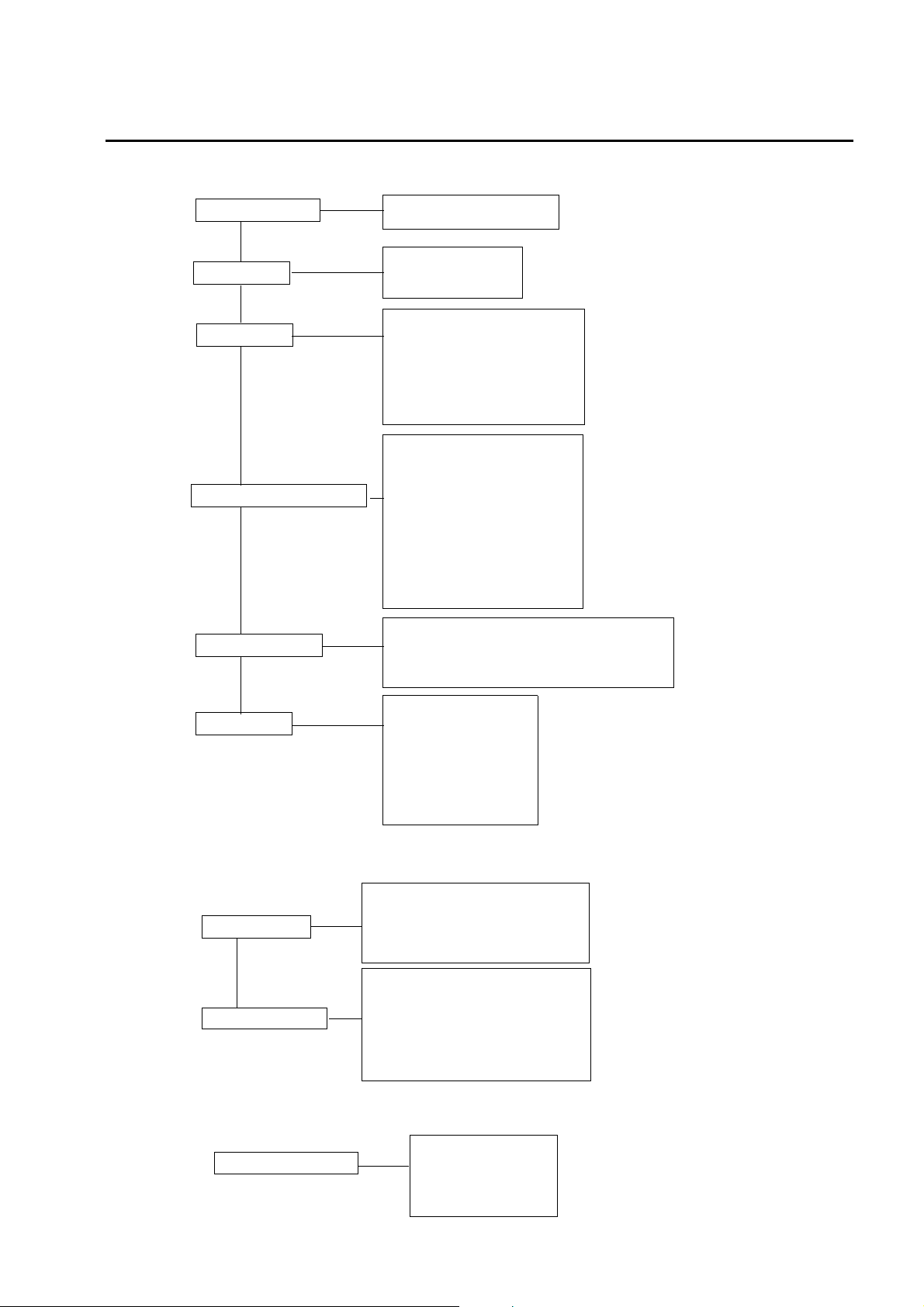
2.4 Setting menu items
2 Device Information
Measurement
Site
Unit for report
Sensor selection
Compensation
Single measurement
Interval measurement
Select site
Create new site
Delete site
TEMP (temperature)
TURB (turbidity)
DO (dissolved oxygen)
COND (electrical conductivity)
SG (seawater specific gravity)
Depth (water depth)
SALT (salinity)
TEMP (temperature)
pH
pH mV
ORP
COND (electrical conductivity)
TURB (turbidity)
DO (dissolved oxygen)
TDS (total dissolved solids)
SALT (salinity)
SG (seawater specific gravity)
DEPTH (water depth)
DO salinity compensation
DO atmospheric pressure compensation
Electrical conductivity temperature coefficient
TDS
“ 3.2.1 Setting measurement
methods ” (page 18)
“ 3.2.2 Setting sites ” (page 20)
“ 3.2.3 Unit for report ” (page 23)
“ 3.2.4 Sensor selection ”
(page 25)
“ 3.2.5 Compensation ”
(page 26)
Language
System
Version
Date/time
Auto power OFF
Display contrast
Initialize
GPS locate*
GPS locating accuracy*
2.5 Calibration menu items
pH
COND (electrical conductivity)
Auto calibration
Manual calibration
TURB (turbidity)
DO (dissolved oxygen)
DEPTH (water depth)
TEMP (temperature)
pH
ORP
COND (electrical conductivity)
TURB (turbidity)
DO (dissolved oxygen)
DEPTH (water depth)
2.6 Data operation menu items
View data
Data operation
Delete data
Check data memory
Calibration record
GPS information*
“ 3.2.6 System settings ” (page 32)
*Only on models with a GPS unit.
“ 3.3.1 Auto calibration ” (page 39)
“ 3.3.2 Manual calibration ” (page 42)
“ 3.5 Data operations ” (page 64)
*Only on models with a GPS unit.
7
3 Basic Operation
3 Basic Operation
3.1 System setup
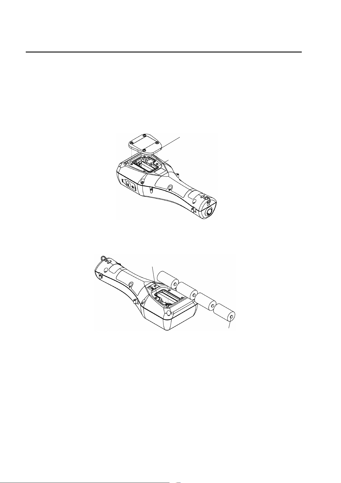
3.1.1 Inserting and replacing the batteries
The control unit is shipped without batteries. Follow the steps below to insert the batteries
when using the system for the first time or replacing old batteries.
1. Loosen the 4 screws on the battery cover by using No. 2 Phillips head screwdriver
and remove the cover.
Battery cover
Batteries
2. If replacing the batteries, discard the old batteries.
3. Insert new batteries in the control unit.
Check that the battery gasket is not dirty or twisted.
Battery gasket
+ side
4. Replace the battery cover and fasten it with the 4 screws.
Tighten the screws to less than 0.5 N⋅m.
8

Note
z
Data and settings will not be lost when the batteries are replaced.
z
If dirty or twisted, the battery gasket will fail to keep the batteries dry. Check its condition before
closing the cover.
z
To ensure long service life, replacing the battery gasket periodically (once a year) is
recommended.
Precautions when using dry cell batteries
z
Batteries to use: LR14 alkaline dry cell batteries (C-size dry cell batteries) or rechargeable nickelmetal hydride dry cell batteries (C-size)
Do not use manganese batteries.
z
Dry cell batteries used incorrectly may leak or burst. Always observe the following
- Orient the batteries correctly (positive and negative ends in correct positions).
- Do not combine new and used batteries, or batteries of different types.
- Remove the batteries when not using the system for a prolonged period.
- If batteries leak, have the system inspected at your nearest Horiba service station.
Battery life
z
The battery life for continuous operation when using C-size alkaline dry cell batteries is
about 70 hours.
z
Using the backlight consumes a proportionate amount of battery power, shortening
battery life.
z
Searching position information using the GPS unit consumes a proportionate amount of
battery power, shortening battery life.
z
Nickel-metal hydride secondary batteries can be used, but the battery life is not
guaranteed since it will vary according to usage (number of times data is saved, number
of charges and amount of each charge). In general, secondary batteries have one-half to
one-third the life of C-size alkaline batteries.
z
The 70-hour battery life figure applies to a control unit operating temperature of 20°C or
more. The battery characteristics shorten the battery life at operating temperatures lower
than 20°C, so check the remaining battery level, and replace the batteries before it
reaches Level 1.
z
The batteries packed with the system at the time of shipment are for checking operation.
Their life is not guaranteed.
z
The 70-hour battery life figure is the amount of operating time the batteries can provide
until the system stops operating. The system may fail during operation if the remaining
battery level is low, so it is a good idea to check the remaining battery level and replace
the batteries with new ones well before the batteries run out completely.
3 Basic Operation
U-51/52
Battery life: 70 hours (backlight off)
U-53
Battery life: 500 measurements (backlight off)
z
Since U-53 is designed for turbidity measurement with wiper, its battery life is estimated in
terms of the number of turbidity measurement sequences performed.
z
Battery power is also consumed by measurement operations other than turbidity measurement.
z
The battery life when turbidity measurement is not performed is about 70 hours.
9
3 Basic Operation
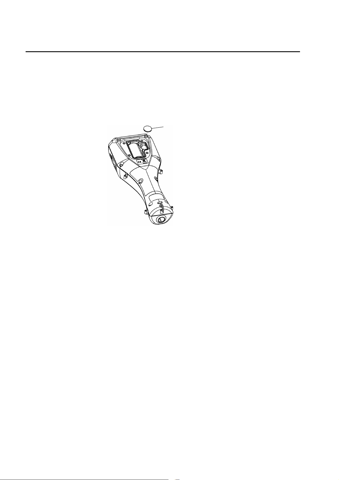
3.1.2 Replacing the coin battery
z
Coin battery to use: CR-2032
z
The coin battery is only for the clock. It will provide problem-free operation for three years,
but when using the clock continuously, it should be replaced every two years as a
precaution.
z
When replacing the coin battery for the clock, leave the control unit ON. If the coin battery
is replaced when the control unit is turned OFF, the clock will be reset to the default
settings.
Coin battery
10
3.1.3 Attaching sensors
Note
z
When attaching or replacing a sensor, wipe any moisture off the sensor probe and sensor.
z
Be sure to keep water out of sensor connectors. If moisture comes in contact with a sensor
connector, blow-dry it with dry air.
z
The sensor probe is not waterproof when the sensor is not mounted.
z
Take care not to tighten the sensor too much.
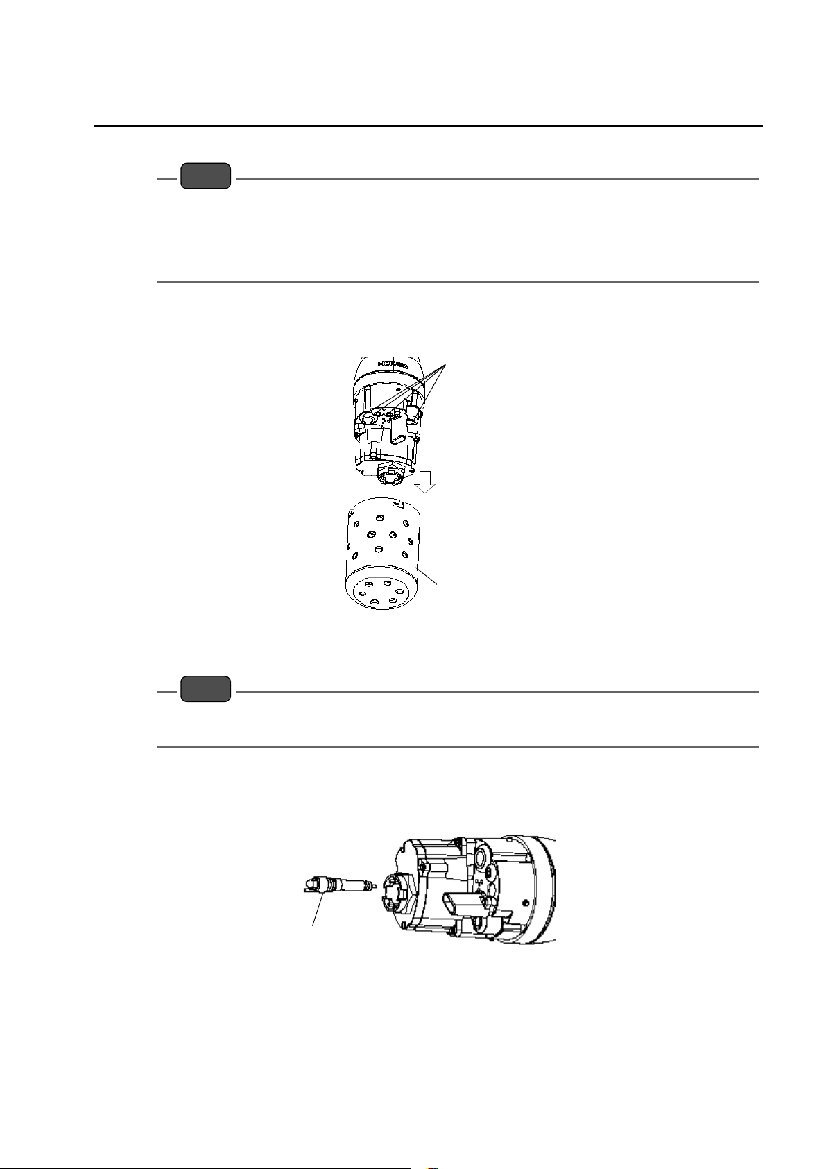
Q Attaching the pH sensor
1.
Remove the sensor guard.
3 Basic Operation
sensor plug
sensor guard
2. Remove the sensor plug.
3. Coat the pH sensor O-ring with a thin layer of silicon grease (part No. 3014017718).
Note
Be sure no grease from the O-ring gets on the sensor connector. If the sensor connector gets grease
on it, wipe it off with a soft cloth soaked in alcohol.
4. Make sure there is no moisture on the sensor probe’s sensor connector (marked
"pH").
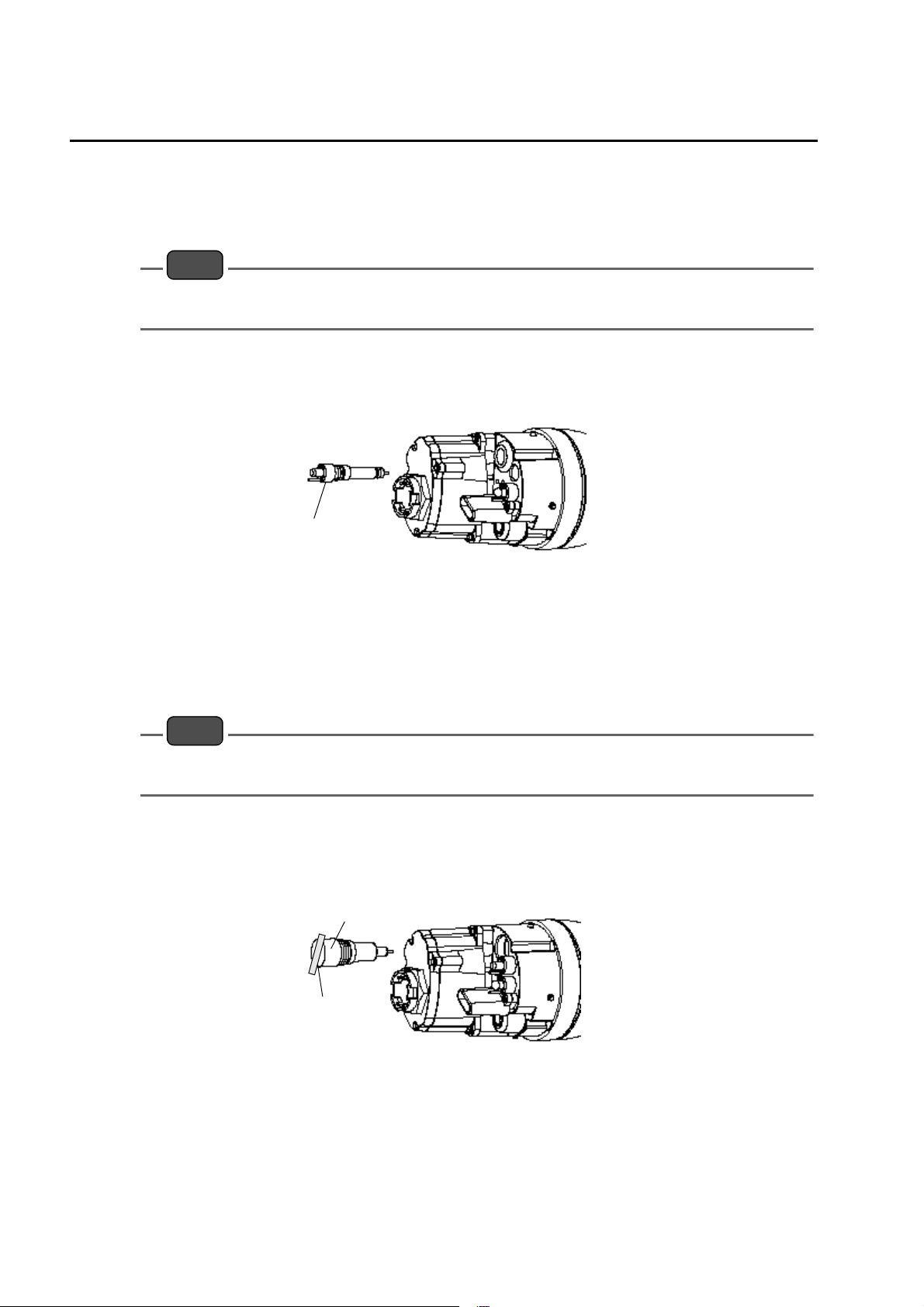
5. Fasten the pH sensor securely by hand.
pH sensor
6. Clean the sensor with an alcohol-soaked cloth.
11
3 Basic Operation
Q Attaching the ORP sensor
Remove the sensor guard.
1.
2. Remove the sensor plug.
3. Coat the ORP sensor O-ring with a thin layer of grease (part No. 3014017718).
Note
Be sure no grease from the O-ring gets on the sensor connector. If the sensor connector gets grease
on it, wipe it off with a soft cloth soaked in alcohol.
4. Make sure there is no moisture on the sensor probe’s sensor connector (marked
"ORP").
5. Fasten the ORP sensor securely by hand.
ORP sensor
6. Clean the sensor with an alcohol-soaked cloth.
Q Attaching the reference electrode
1.
Remove the sensor guard.
2. Remove the sensor plug.
3. Coat the reference electrode O-ring with a thin layer of grease (part No.
3014017718).
Note
Be sure no grease from the O-ring gets on the sensor connector. If the sensor connector gets grease
on it, wipe it off with a soft cloth soaked in alcohol.
4. Make sure there is no moisture on the sensor probe’s sensor connector (marked
"REF").
5. Fasten the reference electrode securely by hand.
6. Remove the tape from the liquid junction part of the reference electrode.
Reference electrode
Tape
12
3 Basic Operation
Q Attaching the dissolved oxygen (DO) sensor
Remove the membrane cap mounted on the DO sensor beforehand, and replace it
1.
with the new membrane cap provided. Replace the internal solution with fresh
solution. The main component of the internal solution is potassium chloride (KCl),
so the old solution can be disposed of down a sink or other drain.
Reference
“ 4.5 Replacing the membrane cap ” (page 87)
2. Screw in the DO sensor to attach it, allowing the internal solution to overflow
slightly.
3. Use a soft cloth to wipe off the internal solution that overflowed onto the DO
sensor.
4. Remove the sensor guard.
5. Remove the sensor plug.
6. Coat the DO sensor O-ring with a thin layer of grease (part No. 3014017718).
Note
Be sure no grease from the O-ring gets on the sensor connector. If the sensor connector gets grease
on it, wipe it off with a soft cloth soaked in alcohol.
7. Make sure there is no moisture on the sensor probe’s sensor connector (marked
"DO").
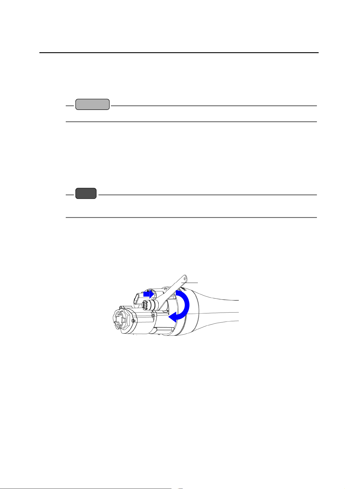
8. Fasten the DO sensor securely using the spanner for DO sensor.
z
Hold the DO sensor with the provided spanner for DO sensor and push the sensor
down. (Step 1 in figure below)
z
Screw the DO sensor in place. (Step 2 in figure below)
①
Spanner for DO sensor
②
13
3 Basic Operation
3.1.4 Connecting the control unit and sensor probe
Note
Connect the control unit with its power OFF.
Zoom
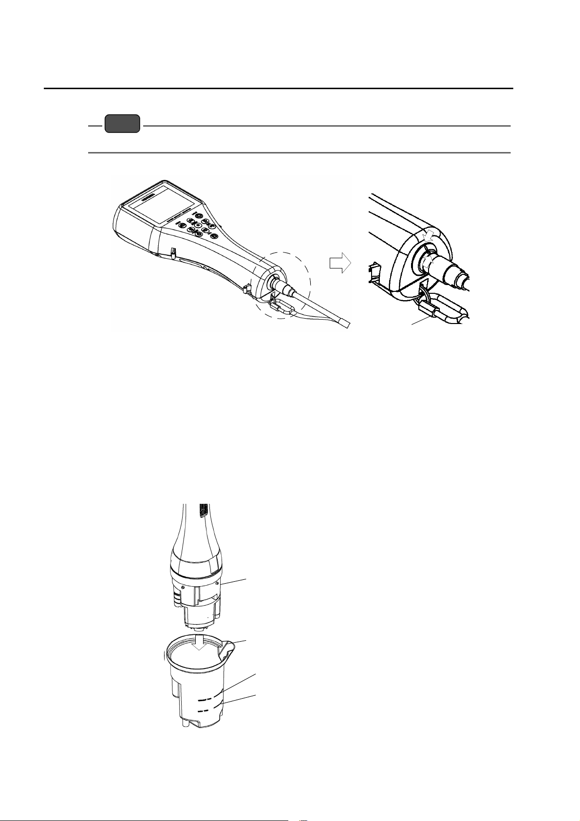
1. Align the red mark on the connector, and press the connector in until you hear it
click.
2. Connect the cable’s hook to the display.
Red mark
Hook
3.1.5 Conditioning
Carry out the steps below when using the unit for the first time or when the system has not
been used for 3 months or longer.
1. Fill the transparent calibration cup to the line with pH 4 standard solution.
The transparent calibration cup has With TURB Measurement and Without TURB
Measurement gauge lines.
2. Insert the sensor probe in the transparent calibration cup.
Sensor probe
Transparent calibration cup
Without TURB Measurement gauge line
14
With TURB Measurement gauge line
3 Basic Operation
Note
Check that all sensors are attached.
3. Press and hold down the control unit’s POWER key for about 3 seconds to turn the
power ON. Leave the unit for at least 20 minutes to condition the sensors.
Note
The operation keys are designed to operate using the pad of a finger, sharp objects can tear the
control unit cover damaging the operation keys.
Tip
z
The procedure for immersing the sensor probe in the pH standard solution is the same as that
described in “ 3.3.1 Auto calibration ” (page 39).
Auto calibration can be performed using the same pH 4 standard solution that was used in the
conditioning procedure.
z
Immersing the sensor in the standard solution is generally required for sensor conditioning, but a
voltage supply is required for DO sensor conditioning. Turning ON the power of the control unit is
necessary during sensor conditioning.
3.1.6 GPS (U-52G, U-53G)
The GPS position measurement precision is proportional to the GPS position measurement
time. When the position measurement precision increases, the position measurement time
also increases. See " Q GPS locating accuracy" (page 17) for how to set the position
measurement precision. See " Q GPS locate" (page 15) below for how to check acquired
GPS data.
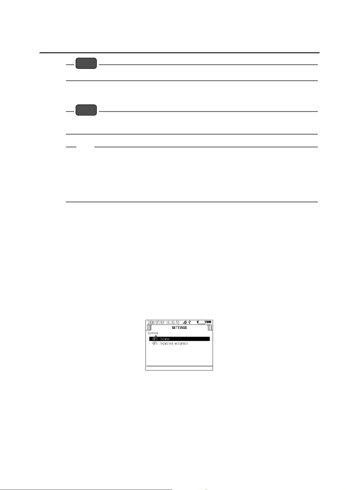
Q GPS locate
1.
Press the right (Z) key to switch the display to the "SETTINGS" screen.
2. Press the down (V) key to move the cursor to "System", then press the ENTER key.
3. Press the down (V) key to move the cursor to "GPS locate", then press the ENTER
key.
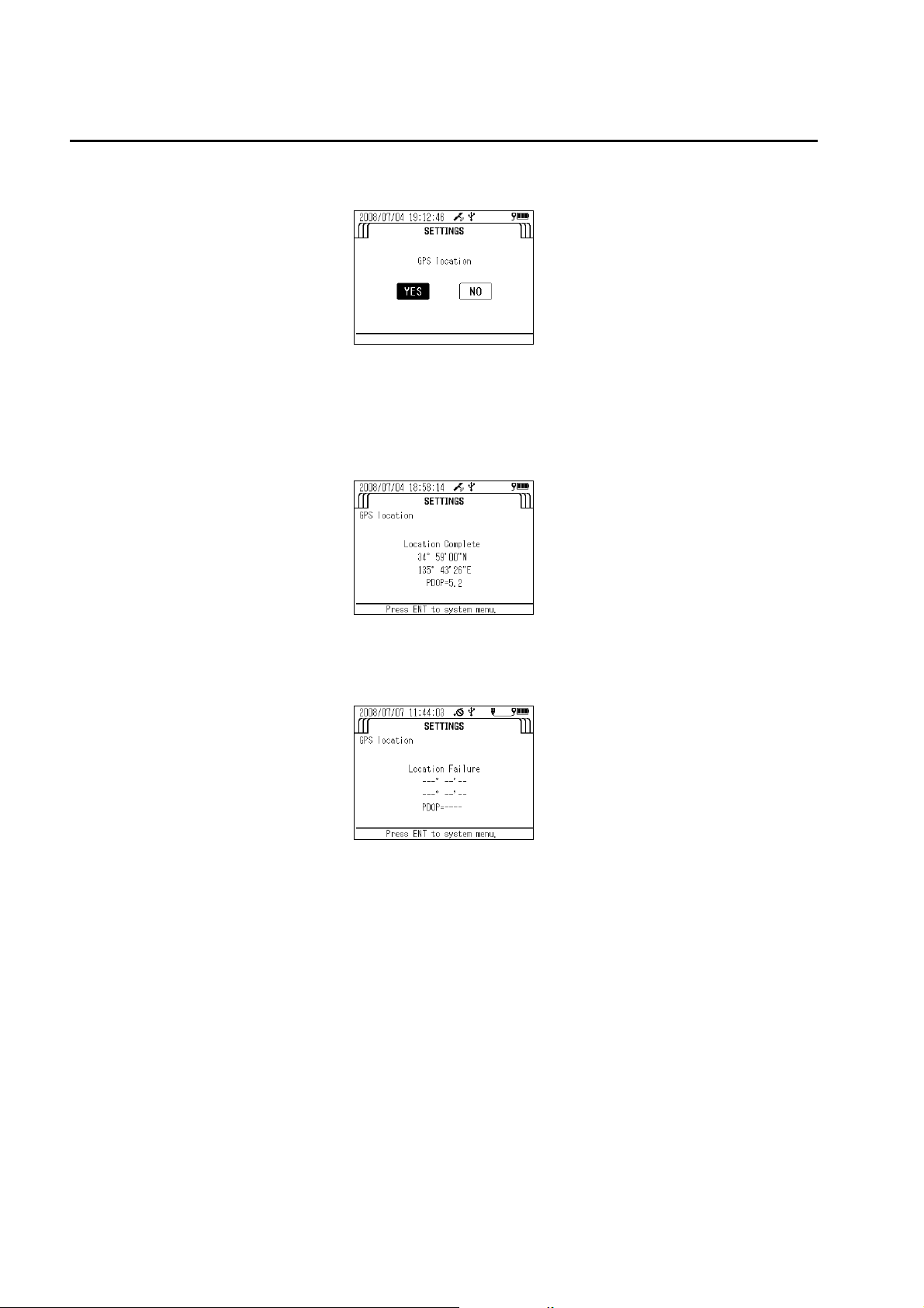
4. The message "Press ENT key to start position measurement." appears. Press the
ENTER key.
15
3 Basic Operation
5. The message "Execute GPS position measurement?" appears. Move the cursor to
6. The message "Warming up. Please wait." appears. Wait until the system has
"YES", then press the ENTER key.
finished warming up (about 10 seconds).
z
Position measurement starts automatically when warmup has finished. Position
measurement is performed up to 10 times.
z
The GPS location complete screen appears after successful position measurement.
z
The GPS location failure screen appears after position measurement has failed. Redo
the measurement in a location free from obstacles, or wait for the meteorological
conditions to improve before redoing the measurement.
16
3 Basic Operation
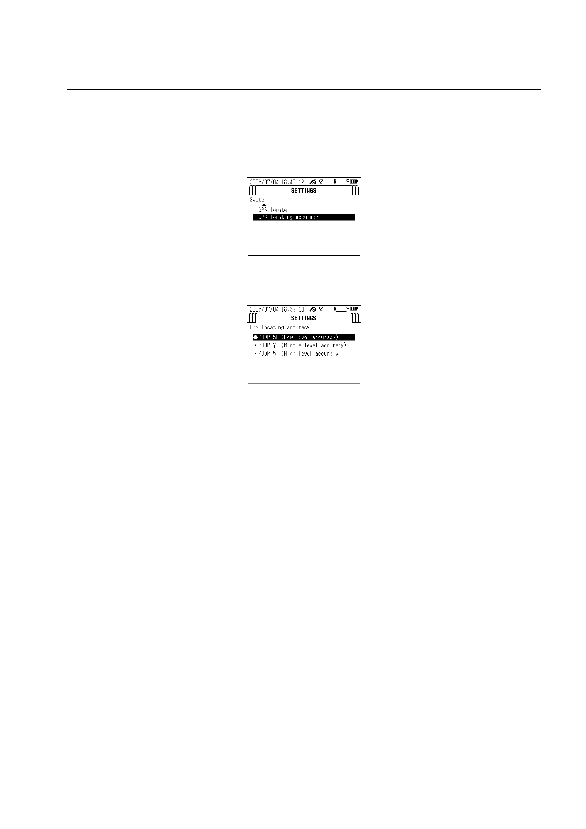
Q GPS locating accuracy
Press the right (Z) key to switch the display to the "SETTINGS" screen.
1.
2. Press the down (V) key to move the cursor to "System", then press the ENTER key.
3. Press the down (V) key to move the cursor to "GPS locating accuracy", then press
the ENTER key.
4. The screen below appears. Move the cursor to the locating accuracy, then press
the ENTER key. The black circle ( ● ) indicates the currently set precision.
17
3 Basic Operation
3.2 Settings
3.2.1 Setting measurement methods
This section describes how to set the measurement method.
Q Measurement methods
U-51/U-52
Single measurement
Interval measurement
U-53
The U-53 turbidity sensor uses a tungsten lamp. The lamp lights for about 10 seconds, and
the average measurement value acquired during this interval is displayed.
Single measurement
Interval measurement
Reference
“ 3.4 Measurement ” (page 61)
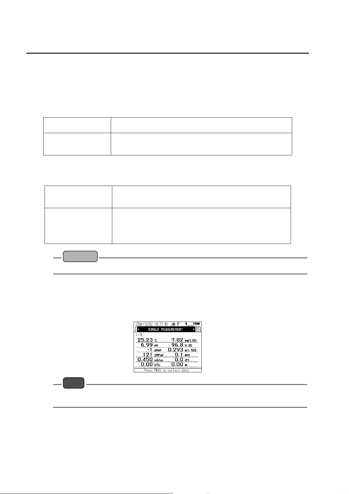
Q Operation method
Press and hold down the control unit’s POWER key for about 3 seconds to turn the
1.
power ON.
The "MEASUREMENT" screen appears after about 10 seconds.
]
Pressing the MEAS key acquires the 5-second average for the selected
measurement parameter.
Pressing the MEAS key acquires and saves the 5-second average for the
selected measurement parameter in the set interval. The measurement
interval can be set to any value between 10 seconds and 24 hours.
Pressing the MEAS key acquires the 5-second average for the selected
measurement parameter after wiper operation. The 10-second average is
acquired when measuring turbidity.
Pressing the MEAS key acquires and saves the 5-second average for the
selected measurement parameter in the set interval. The 10-second
average is acquired when measuring turbidity. The measurement interval
can be set to any value between 10 seconds (final check of this value
required; 30 seconds may be better for U-52) and 24 hour.
18
Note
The operation keys are designed to operate using the pad of a finger, sharp objects can tear the
control unit cover damaging the operation keys.
2. Press the right (Z) key to switch the display to the "SETTINGS" screen.
 Loading...