

horiba TPNA-500 Instruction Manual

Automatic Total Nitrogen/Phosphorus Monitoring
System
TPNA-500
Instruction Manual
CODE:GZ0000371324D

Preface
This manual describes the operation of the Automatic Total Nitrogen/Phosphorus Monitoring
System, TPNA-500.
Be sure to read this manual before using the product to ensure proper and safe operation of
the product. Also safely store the manual so it is readily available whenever necessary.
Product specifications and appearance, as well as the contents of this manual are subject to
change without notice.
Warranty and responsibility
HORIBA Advanced Techno, Co., Ltd. warrants that the Product shall be free from defects in
material and workmanship and agrees to repair or replace free of charge, at option of HORIBA
Advanced Techno, Co., Ltd., any malfunctioned or damaged Product attributable to
responsibility of HORIBA Advanced Techno, Co., Ltd. for a period of one (1) year from the
delivery unless otherwise agreed with a written agreement. In any one of the following cases,
none of the warranties set forth herein shall be extended;
Any malfunction or damage attributable to improper operation
Any malfunction attributable to repair or modification by any person not authorized by
HORIBA Advanced Techno, Co., Ltd.
Any malfunction or damage attributable to the use in an environment not specified in this
manual
Any malfunction or damage attributable to violation of the instructions in this manual or
operations in the manner not specified in this manual
Any malfunction or damage attributable to any cause or causes beyond the reasonable
control of HORIBA Advanced Techno, Co., Ltd. such as natural disasters
Any deterioration in appearance attributable to corrosion, rust, and so on
Replacement of consumables
HORIBA Advanced Techno, Co., Ltd. SHALL NOT BE LIABLE FOR ANY DAMAGES
RESULTING FROM ANY MALFUNCTIONS OF THE PRODUCT, ANY ERASURE OF DATA,
OR ANY OTHER USES OF THE PRODUCT.
Trademarks
CompactFlash is a registered trademark or trademark of SanDisk Corporation in the
United States and other countries.
Modbus is a registered trademark of Schneider Automation Inc.
PharMed is a trademark of Saint-Gobain Performance Plastics Corporation.
Other company names and brand names are either registered trademarks or trademarks of
the respective companies. (R), (TM) symbols may be omitted in this manual.
February, 2019 © 2015 2019 HORIBA Advanced Techno, Co., Ltd.

Regulations
Note
Conformable Directive
This equipment conforms to the following directives and standards:
EMC:
RoHS:
Warning:
When the sensor cable, the transmission cable, or the contact input cable is extended to 30 m or
longer, the surge test specified in the EMC directive for CE marking is not applied.
EN61326-1
Class A, Industrial electromagnetic environment
EN50581
9. Industrial monitoring and control instruments
This is a Class A product. In a domestic environment this
product may cause radio interference in which case the user
may be required to take adequate measures.
Installation environment
This product is designed for the following environment.
Overvoltage Category II
Pollution degree 2
Information on disposal of electrical and electronic equipment
and disposal of batteries and accumulators
The crossed out wheeled bin symbol with underbar shown on the product or accompanying
documents indicates the product requires appropriate treatment, collection and recycle for
waste electrical and electronic equipment (WEEE) under the Directive 2012/19/EU, and/or
waste batteries and accumulators under the Directive 2006/66/EC in the European Union.
The symbol might be put with one of the chemical symbols below. In this case, it satisfies the
requirements of the Directive 2006/66/EC for the object chemical.
This product should not be disposed of as unsorted household waste.
Your correct disposal of WEEE, waste batteries and accumulators will contribute to reducing
wasteful consumption of natural resources, and protecting human health and the environment
from potential negative effects caused by hazardous substance in products.
Contact your supplier for information on applicable disposal methods.
FCC rules
Any changes or modifications not expressly approved by the party responsible for compliance
shall void the user's authority to operate the equipment.
Warning
This equipment has been tested and found to comply with the limits for a Class A digital
device, pursuant to part 15 of the FCC Rules. These limits are designed to provide reasonable
protection against harmful interference when the equipment is operated in a commercial
environment. This equipment generates, uses, and can radiate radio frequency energy and, if
not installed and used in accordance with the instruction manual, may cause harmful
interference to radio communications.
Operation of this equipment in a residential area is likely to cause harmful interference in
which case the user will be required to correct the interference at his own expense.
Korea certification
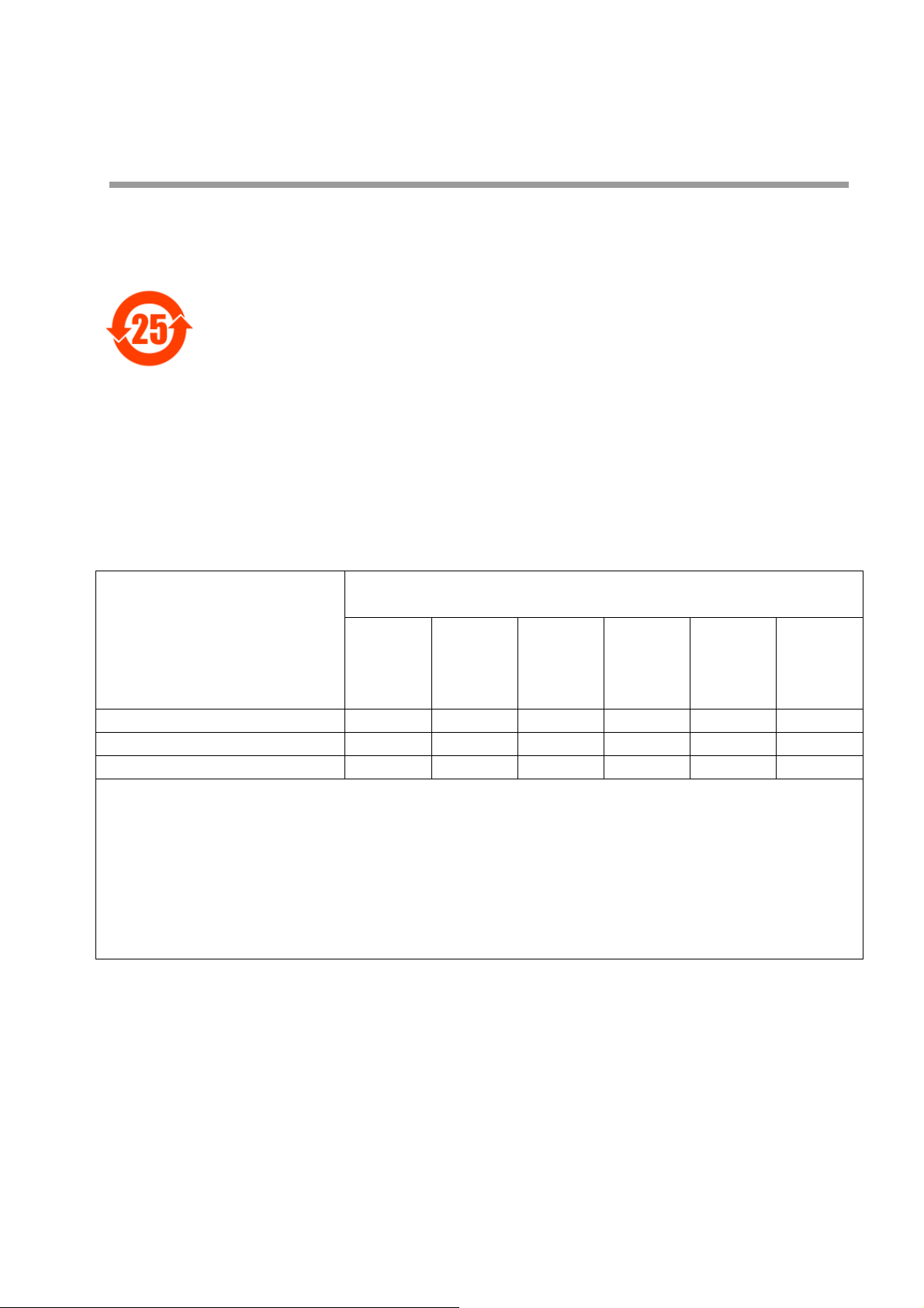
China regulation
本标记适用在中华人民共和国销售电器电子产品,标记中央的数字表示环境保护使用期限的年数。(不是表
示产品质量保证期间。) 只要遵守这个产品有关的安全和使用注意事项,从制造日开始算起在这个年限内,
不会给环境污染、人体和财产带来严重的影响。请不要随意废弃本电器电子产品。
This marking is applied to electric and electronic products sold in the People's Republic of China. The
figure at the center of the marking indicates the environmental protection use period in years. (It does not
indicate a product guarantee period.) It guarantees that the product will not cause environment pollution
nor serious influence on human body and property within the period of the indicated years which is
counted from the date of manufacture as far as the safety and usage precautions for the product are
observed. Do not throw away this product without any good reason.
本マークは、中華人民共和国で販売される電気電子製品に適用され、マークの中央の数字は環境保護使用
期限の年数を意味します(製品の品質保証期間を示すものではありません)。この製品に関する安全や使
用上の注意をお守り頂く限り、製造日から起算するこの年限内では、環境汚染や人体や財産に深刻な影響
を及ぼすことはありません。本製品をみだりに廃棄しないでください。
产品中有害物质的名称及含量
Name and amount of hazardous substance used in a product
有害物质
Hazardous substance
部件名称
Unit name
操作单元
分析单元
主机柜
本表格依据 SJ/T 11364 的规定编制。
This form is prepared in accordance with SJ/T 11364.
○: 表示该有害物质在该部件所有均质材料中的含量均在 GB/T 26572 规定的限量要求以下。
Denotes that the amount of the hazardous substance contained in all of the homogeneous materials used in the
component is below the limit on the acceptable amount stipulated in the GB/T 26572.
×:
表示该有害物质至少在该部件的某一均质材料中的含量超出 GB/T 26572 规定的限量要求。
Denotes that the amount of the hazardous substance contained in any of the homogeneous materials used in the
component is above the limit on the acceptable amount stipulated in the GB/T 26572.
Operation unit ×
Analyzer unit × ×
Main cabinet
铅
Lead
(Pb)
○○○○○○
汞
Mercury
(Hg)
○○○○○
镉
Cadmium
(Cd)
○○○○
六价铬
Hexavalent
chromium
(Cr (VI))
多溴联苯
Polybromo-
biphenyl
(PBB)
多溴二苯醚
Polybromo-
diphenyl
ether
(PBDE)
For Your Safety
Hazard classification and warning symbols
Warning messages are described in the following manner. Read the messages and follow the
instructions carefully.
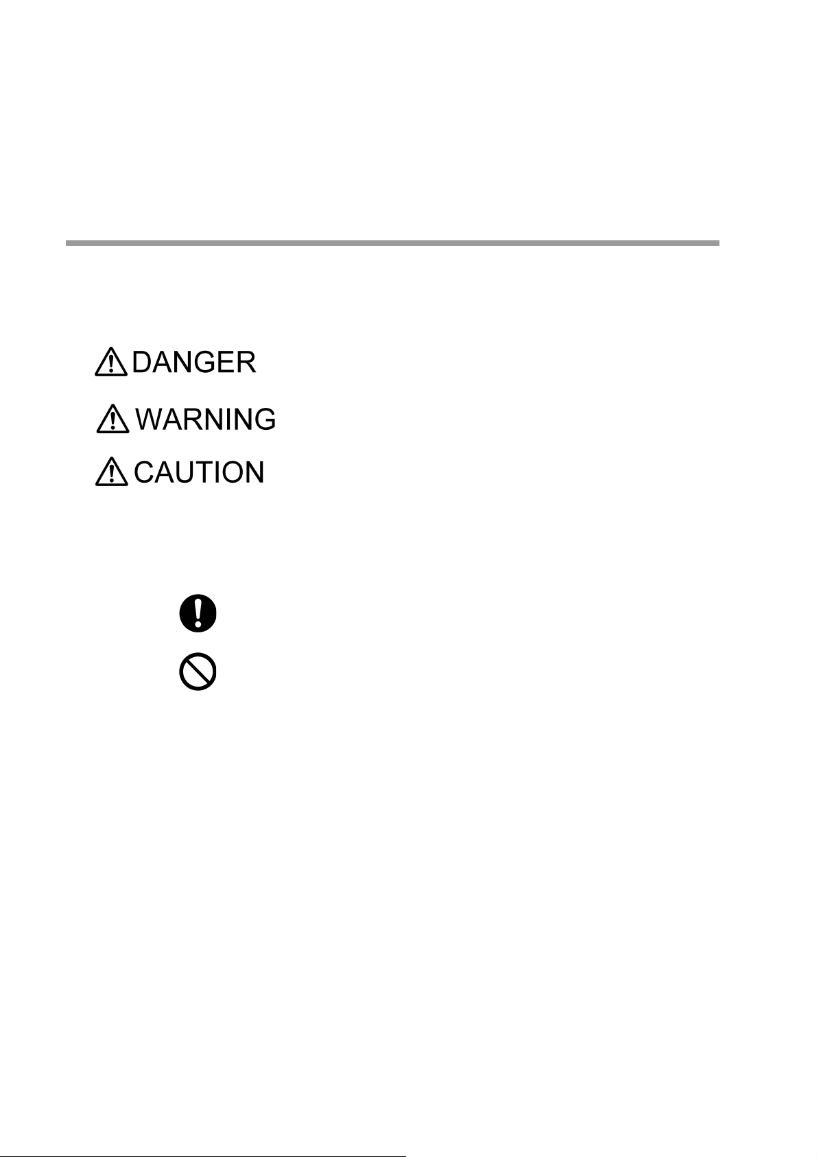
Hazard classification
This indicates an imminently hazardous situation which, if not avoided, will
result in death or serious injury. This is to be limited to the most extreme
situations.
This indicates a potentially hazardous situation which, if not avoided, could
result in death or serious injury.
This indicates a potentially hazardous situation which, if not avoided, may
result in minor or moderate injury. It may also be used to alert against
unsafe practices.
Warning symbols
Description of what should be done, or what should be followed
Description of what should never be done, or what is prohibited
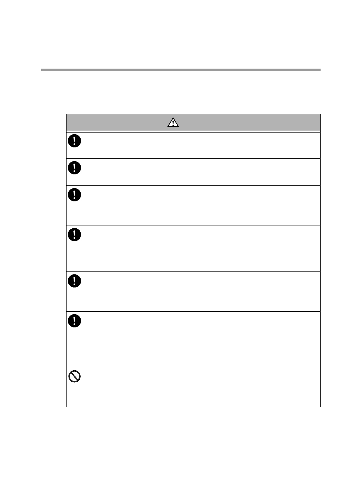
Safety precautions
WARNING
This section provides precautions for using the product safely and correctly and to prevent
injury and damage. The terms of DANGER, WARNING, and CAUTION indicate the degree of
imminency and hazardous situation. Read the precautions carefully as it contains important
safety messages.
Electric shock hazard
In order to prevent electric shock, be sure to ground the equipment. At this point, however, avoid
connecting it to hazardous locations, such as gas piping.
Electric shock hazard
Improper terminal connection can cause an electric shock and malfunction of the equipment. Be
extremely careful not to connect the terminals incorrectly.
Electric shock hazard
• Before connecting wiring to the terminal block, be sure to cut off the external power supply. Failure
to do so may cause an electric shock.
• The operation panel and the terminal block cover for the rear terminal block should only be
opened/closed by a person with full electrical knowledge.
Beware of waste liquid
The waste liquid contains acid, alkali, and heavy metals. When you handle the waste liquid, be sure to
wear protective gloves and goggles so that you will not come in direct contact with the waste liquid.
If it gets on your skin or in your eyes, rinse it off with a plenty of water immediately and contact your
doctor.
If you swallow it accidentally, contact your doctor immediately.
Chemical hazard
Some reagents are poisonous and thus it is extremely dangerous if they are touched by hand. When
replacing the reagent bottle, be sure to wear protective goggles and gloves, and be extremely careful
so that your skin will not come in direct contact with reagents. When replacing the reagent bottle, the
reagent may spill off from the bottle. If it spills off, wipe it off completely.
Chemical hazard
Dissolving the reagent generates hydrochloric vapor and heat. When mixing the cleaning solution, be
sure to wear protective goggles and gloves.
• Dissolve the reagent in a well-ventilated area such as a draft chamber.
• Always pour hydrochloric acid into pure water. Never pour pure water into hydrochloric acid.
• 35% to 37% hydrochloric acid is poisonous. Be extremely careful when handling it.
• If it comes in contact with your skin, rinse it off well with running water.
• If it gets in your eyes, rinse it off well with running water, and then immediately consult a doctor.
Fire or electric shock
• Do not bundle the power supply cord during use.
• Do not damage the power supply cord nor apply an excessive load to it, such as bending and
stretching it repeatedly, putting a heavy thing on it.
If may result in overheating, a fire, an electrical shock, or breakdown.
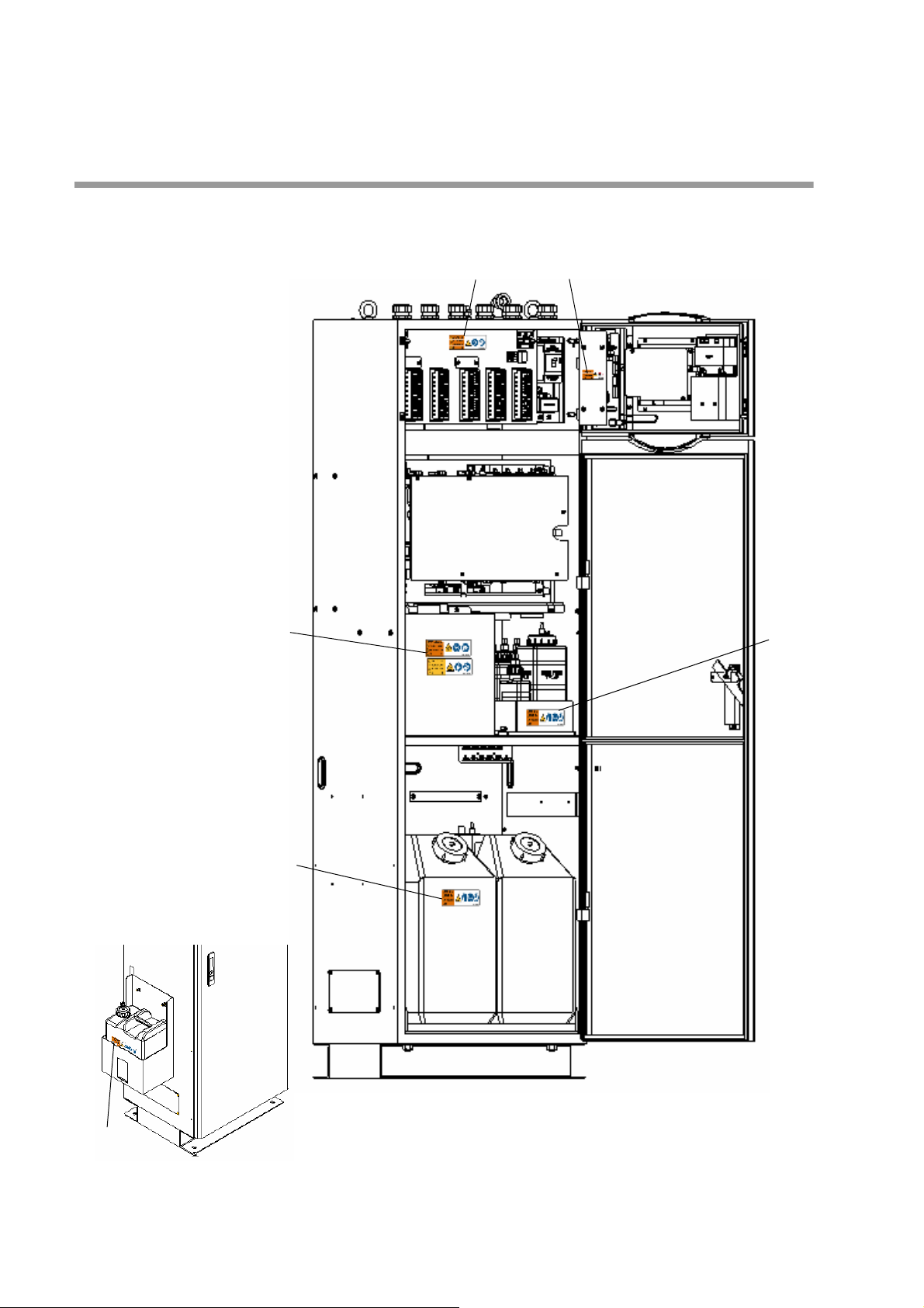
Attachment location and type of warning labels
(1)
(2)
(6)
(5)
(3)
(4)
(For automatic hydrochloric
acid cleaning specification)
Attachment location of warning labels
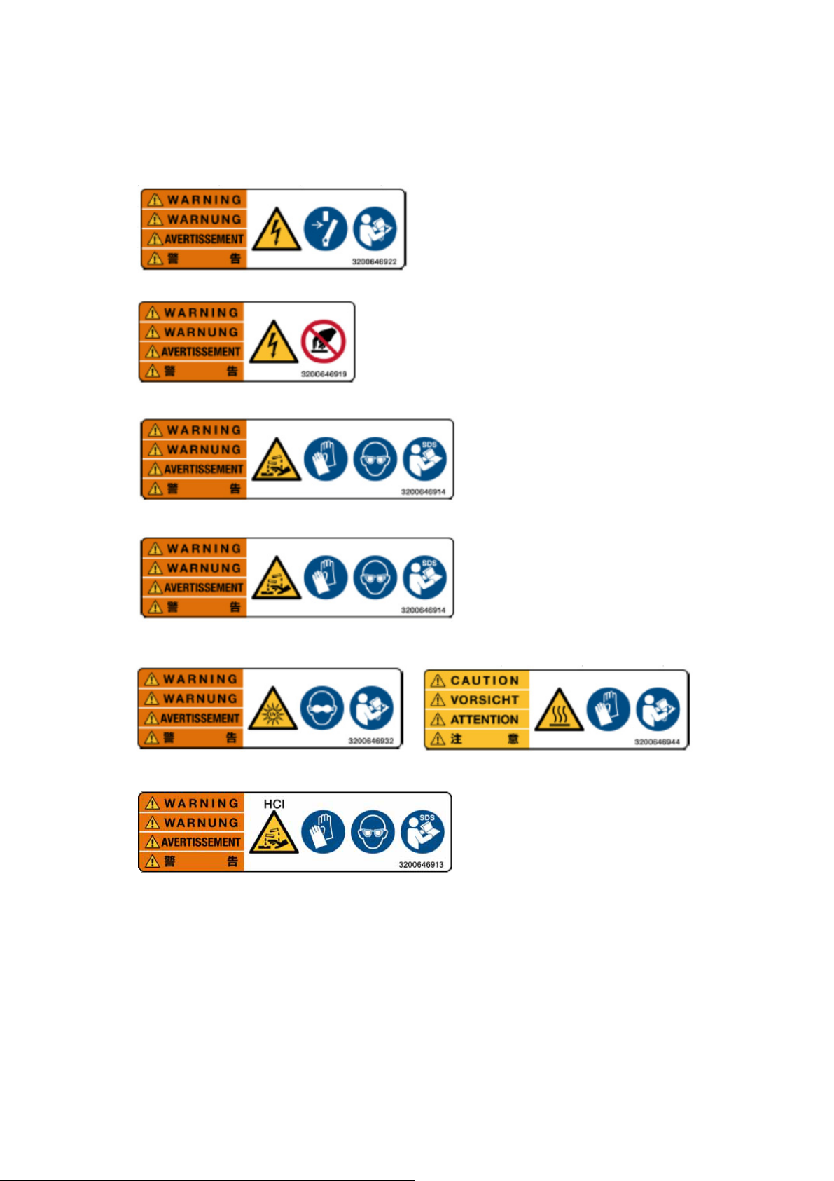
(1)
(2)
(4)
(3)
(5) 2 type labels
(6) For automatic hydrochloric acid cleaning specification
Type

Product Handling Information
Operational precautions
Use of the product in a manner not specified by the manufacturer may impair the protection
provided by the product. And it may also reduce product performance.
Exercise the following precautions:
Only use the product including accessories for their intended purpose.
Use the equipment in an environment that does not contain corrosive gas.
Do not apply external shock or excessive vibration to the equipment. When relocating the
equipment, contact our service or sales office.
Do not switch the power ON and OFF immediately.
Do not operate the touch panel using the tip of your finger nail or a tool with a sharp edge,
or with wet hands.
Do not use solutions such as organic solvents.
Be extremely careful when handling chemicals.
A new reagent bottle is fully charged with reagent. If you grab the side of the bottle while
the cap is open, the reagent may spill out. When opening the cap of the reagent bottle for
setting or replacing the reagent, be careful not to spill the reagent. For example, place the
bottle on a flat surface.
Perform the installation work while taking the features of the analyzer into consideration.
Also, ensure an environment in which the equipment can operate normally. Take
appropriate action so that the equipment will not be damaged even when the equipment
no longer operates correctly due to deterioration or the operational setting conditions of
the equipment, or any unexpected phenomenon.
Disposal of the product
When disposing of the product, follow the related laws and/or regulations of your country.
The waste liquid of this equipment contains acid.
The mercury lamps in this product contains 18 mg of mercury.

Manual Information
Note
Reference
Tip
Description in this manual
This interprets the necessary points for correct operation and notifies the important points for
handling the product.
This indicates the part where to refer for information.
This indicates reference information.


Contents
Before Using the Product . . . . . . . . . . . . . . . . . . . . . . . . . . . . . . . . 1
Preface . . . . . . . . . . . . . . . . . . . . . . . . . . . . . . . . . . . . . . . . . . . . . . . . . . . 1
Names of each part . . . . . . . . . . . . . . . . . . . . . . . . . . . . . . . . . . . . . . . . . 2
Analyzer . . . . . . . . . . . . . . . . . . . . . . . . . . . . . . . . . . . . . . . . . . . . . . . . . . . . . . . 2
Operation section. . . . . . . . . . . . . . . . . . . . . . . . . . . . . . . . . . . . . . . . . . . . . . . . 5
Display . . . . . . . . . . . . . . . . . . . . . . . . . . . . . . . . . . . . . . . . . . . . . . . . . . . . . . . . 6
How to change authority. . . . . . . . . . . . . . . . . . . . . . . . . . . . . . . . . . . . . . 10
Connection. . . . . . . . . . . . . . . . . . . . . . . . . . . . . . . . . . . . . . . . . . . . 11
Signal wiring . . . . . . . . . . . . . . . . . . . . . . . . . . . . . . . . . . . . . . . . . . . . . . . 11
External input/output . . . . . . . . . . . . . . . . . . . . . . . . . . . . . . . . . . . . . . . . . . . . . 11
Analog output. . . . . . . . . . . . . . . . . . . . . . . . . . . . . . . . . . . . . . . . . . . . . . . . . . . 13
Analog input . . . . . . . . . . . . . . . . . . . . . . . . . . . . . . . . . . . . . . . . . . . . . . . . . . . . 17
Contact output . . . . . . . . . . . . . . . . . . . . . . . . . . . . . . . . . . . . . . . . . . . . . . . . . . 19
Contact input . . . . . . . . . . . . . . . . . . . . . . . . . . . . . . . . . . . . . . . . . . . . . . . . . . . 24
Serial input/output (RS-485/RS-232C) . . . . . . . . . . . . . . . . . . . . . . . . . . . 29
Preparation for Operation. . . . . . . . . . . . . . . . . . . . . . . . . . . . . . . . 30
Preparation of printer . . . . . . . . . . . . . . . . . . . . . . . . . . . . . . . . . . . . . . . . 30
Installation of reagent bottle . . . . . . . . . . . . . . . . . . . . . . . . . . . . . . . . . . . 31
Preparation of reagent . . . . . . . . . . . . . . . . . . . . . . . . . . . . . . . . . . . . . . . 34
Preparing potassium peroxodisulfate aqueous solution [Reagent A] . . . . . . . . 35
Preparing sodium hydroxide aqueous solution [Reagent B] . . . . . . . . . . . . . . . 35
Preparing dilute sulfuric acid solution [Reagent C] . . . . . . . . . . . . . . . . . . . . . . 35
Preparing L-ascorbic acid aqueous solution [Reagent D] . . . . . . . . . . . . . . . . . 36
Preparing mixed reagent (ammonium molybdate + potassium antimonyl tartrate sesqui-
hydrate) [Reagent E] . . . . . . . . . . . . . . . . . . . . . . . . . . . . . . . . . . . . . . . . . . . . . 36
Preparing hydrochloric acid solution [Reagent F] . . . . . . . . . . . . . . . . . . . . . . . 36
Preparation procedure of span solution . . . . . . . . . . . . . . . . . . . . . . . . . . 37
Preparation for pure water supply . . . . . . . . . . . . . . . . . . . . . . . . . . . . . . 39
Installation of chemical tank (for automatic hydrochloric acid cleaning specifica-
tion). . . . . . . . . . . . . . . . . . . . . . . . . . . . . . . . . . . . . . . . . . . . . . . . . . . . . . 45
Line cleaning solution . . . . . . . . . . . . . . . . . . . . . . . . . . . . . . . . . . . . . . . . . . . . 46
Operation . . . . . . . . . . . . . . . . . . . . . . . . . . . . . . . . . . . . . . . . . . . . . 47
Operation method. . . . . . . . . . . . . . . . . . . . . . . . . . . . . . . . . . . . . . . . . . . 47
For initial operation . . . . . . . . . . . . . . . . . . . . . . . . . . . . . . . . . . . . . . . . . . . . . . 48
Operation start . . . . . . . . . . . . . . . . . . . . . . . . . . . . . . . . . . . . . . . . . . . . . 49

Operation stop . . . . . . . . . . . . . . . . . . . . . . . . . . . . . . . . . . . . . . . . . . . . 50
When stopping the equipment for over three days . . . . . . . . . . . . . . . . . . . . . . 50
When shutting down the analyzer for more than two weeks. . . . . . . . . . . . . . . 50
Operation restart. . . . . . . . . . . . . . . . . . . . . . . . . . . . . . . . . . . . . . . . . . . 52
Calibration . . . . . . . . . . . . . . . . . . . . . . . . . . . . . . . . . . . . . . . . . . . . 53
Calibration pattern. . . . . . . . . . . . . . . . . . . . . . . . . . . . . . . . . . . . . . . . . . 53
Calibration procedure . . . . . . . . . . . . . . . . . . . . . . . . . . . . . . . . . . . . . . . 55
Function. . . . . . . . . . . . . . . . . . . . . . . . . . . . . . . . . . . . . . . . . . . . . . 56
Description . . . . . . . . . . . . . . . . . . . . . . . . . . . . . . . . . . . . . . . . . . . . . . . 56
Main screen . . . . . . . . . . . . . . . . . . . . . . . . . . . . . . . . . . . . . . . . . . . . . . 56
List of functions. . . . . . . . . . . . . . . . . . . . . . . . . . . . . . . . . . . . . . . . . . . . 57
Hierarchy of functions . . . . . . . . . . . . . . . . . . . . . . . . . . . . . . . . . . . . . . . 58
To display the [MENU] item screen . . . . . . . . . . . . . . . . . . . . . . . . . . . . 62
[MENU] - [SETTING]. . . . . . . . . . . . . . . . . . . . . . . . . . . . . . . . . . . . . . . . 63
OPERATION SET. . . . . . . . . . . . . . . . . . . . . . . . . . . . . . . . . . . . . . . . . . . . . . . 63
MEAS. LINE SET . . . . . . . . . . . . . . . . . . . . . . . . . . . . . . . . . . . . . . . . . . . . . . . 75
OUTPUT SET . . . . . . . . . . . . . . . . . . . . . . . . . . . . . . . . . . . . . . . . . . . . . . . . . . 83
PAYLOAD SET . . . . . . . . . . . . . . . . . . . . . . . . . . . . . . . . . . . . . . . . . . . . . . . . . 98
SYSTEM SET . . . . . . . . . . . . . . . . . . . . . . . . . . . . . . . . . . . . . . . . . . . . . . . . . . 100
[MENU] - [MAINTENANCE] . . . . . . . . . . . . . . . . . . . . . . . . . . . . . . . . . . 111
REAG.. . . . . . . . . . . . . . . . . . . . . . . . . . . . . . . . . . . . . . . . . . . . . . . . . . . . . . . . 111
PERIODIC CHECK . . . . . . . . . . . . . . . . . . . . . . . . . . . . . . . . . . . . . . . . . . . . . . 115
EXT. ANALOG OUTPUT ADJUST . . . . . . . . . . . . . . . . . . . . . . . . . . . . . . . . . . 116
STEP ACTION . . . . . . . . . . . . . . . . . . . . . . . . . . . . . . . . . . . . . . . . . . . . . . . . . 117
SEPARATE ACTION . . . . . . . . . . . . . . . . . . . . . . . . . . . . . . . . . . . . . . . . . . . . 119
[MENU] - [CHECK] . . . . . . . . . . . . . . . . . . . . . . . . . . . . . . . . . . . . . . . . . 122
MACHINE INFORMATION . . . . . . . . . . . . . . . . . . . . . . . . . . . . . . . . . . . . . . . . 122
EXT. POINT INPUT . . . . . . . . . . . . . . . . . . . . . . . . . . . . . . . . . . . . . . . . . . . . . 123
EXT. POINT OUTPUT . . . . . . . . . . . . . . . . . . . . . . . . . . . . . . . . . . . . . . . . . . . 124
EXT. ANALOG INPUT . . . . . . . . . . . . . . . . . . . . . . . . . . . . . . . . . . . . . . . . . . . 125
EXT. ANALOG OUTPUT . . . . . . . . . . . . . . . . . . . . . . . . . . . . . . . . . . . . . . . . . 126
INT. ANALOG INPUT . . . . . . . . . . . . . . . . . . . . . . . . . . . . . . . . . . . . . . . . . . . . 127
To display the [DATA] item screen . . . . . . . . . . . . . . . . . . . . . . . . . . . . . 128
[DATA] - [LOG DATA] . . . . . . . . . . . . . . . . . . . . . . . . . . . . . . . . . . . . . . . 131
MEASURE VALUE . . . . . . . . . . . . . . . . . . . . . . . . . . . . . . . . . . . . . . . . . . . . . . 131
HOUR REPORT . . . . . . . . . . . . . . . . . . . . . . . . . . . . . . . . . . . . . . . . . . . . . . . . 133
[DATA] - [GRAPH] . . . . . . . . . . . . . . . . . . . . . . . . . . . . . . . . . . . . . . . . . 135

MEASURE VALUE . . . . . . . . . . . . . . . . . . . . . . . . . . . . . . . . . . . . . . . . . . . . . . 135
TREND GRAPH (MEASURE VALUE). . . . . . . . . . . . . . . . . . . . . . . . . . . . . . . . 137
HOUR REPORT . . . . . . . . . . . . . . . . . . . . . . . . . . . . . . . . . . . . . . . . . . . . . . . . 139
OPTICAL SIGNAL . . . . . . . . . . . . . . . . . . . . . . . . . . . . . . . . . . . . . . . . . . . . . . . 141
TREND GRAPH (OPTICAL SIGNAL) . . . . . . . . . . . . . . . . . . . . . . . . . . . . . . . . 144
[DATA] - [CALIBRATION HISTORY] . . . . . . . . . . . . . . . . . . . . . . . . . . . . 146
[DATA] - [ALARM HISTORY] . . . . . . . . . . . . . . . . . . . . . . . . . . . . . . . . . . 147
[DATA] - [SAVE TO USB]. . . . . . . . . . . . . . . . . . . . . . . . . . . . . . . . . . . . . 148
About the data to be stored . . . . . . . . . . . . . . . . . . . . . . . . . . . . . . . . . . . . . . . . 149
[DATA] - [DATA CLEAR] . . . . . . . . . . . . . . . . . . . . . . . . . . . . . . . . . . . . . 156
[START] . . . . . . . . . . . . . . . . . . . . . . . . . . . . . . . . . . . . . . . . . . . . . . . . . . 157
[STOP] . . . . . . . . . . . . . . . . . . . . . . . . . . . . . . . . . . . . . . . . . . . . . . . . . . . 158
[POWER] . . . . . . . . . . . . . . . . . . . . . . . . . . . . . . . . . . . . . . . . . . . . . . . . . 160
Modbus. . . . . . . . . . . . . . . . . . . . . . . . . . . . . . . . . . . . . . . . . . . . . . . 161
Overview. . . . . . . . . . . . . . . . . . . . . . . . . . . . . . . . . . . . . . . . . . . . . . . . . . 161
Software overview . . . . . . . . . . . . . . . . . . . . . . . . . . . . . . . . . . . . . . . . . . . . . . . 161
Function code . . . . . . . . . . . . . . . . . . . . . . . . . . . . . . . . . . . . . . . . . . . . . . . . . . 161
Exception code . . . . . . . . . . . . . . . . . . . . . . . . . . . . . . . . . . . . . . . . . . . . . . . . . 162
Slave address . . . . . . . . . . . . . . . . . . . . . . . . . . . . . . . . . . . . . . . . . . . . . . . . . . 162
Address mapping . . . . . . . . . . . . . . . . . . . . . . . . . . . . . . . . . . . . . . . . . . . 163
Data format example . . . . . . . . . . . . . . . . . . . . . . . . . . . . . . . . . . . . . . . . 174
Data definition sheet. . . . . . . . . . . . . . . . . . . . . . . . . . . . . . . . . . . . . . . . . 177
How to use data . . . . . . . . . . . . . . . . . . . . . . . . . . . . . . . . . . . . . . . . . . . . 186
MEAS. (STATUS) . . . . . . . . . . . . . . . . . . . . . . . . . . . . . . . . . . . . . . . . . . . . . . . 186
MEAS. (CURRENT ALARM) . . . . . . . . . . . . . . . . . . . . . . . . . . . . . . . . . . . . . . . 186
MEAS. (MEASURE VALUE) . . . . . . . . . . . . . . . . . . . . . . . . . . . . . . . . . . . . . . . 186
MEAS. (Hour Report History). . . . . . . . . . . . . . . . . . . . . . . . . . . . . . . . . . . . . . . 186
MEAS. (Day Report History) . . . . . . . . . . . . . . . . . . . . . . . . . . . . . . . . . . . . . . . 186
MEAS. (EXT. ANALOG INPUT). . . . . . . . . . . . . . . . . . . . . . . . . . . . . . . . . . . . . 186
MEAS. (EXT. POINT INPUT). . . . . . . . . . . . . . . . . . . . . . . . . . . . . . . . . . . . . . . 186
CONTROL (EXT. ANALOG INPUT) . . . . . . . . . . . . . . . . . . . . . . . . . . . . . . . . . 186
CONTROL (EXT. POINT INPUT) . . . . . . . . . . . . . . . . . . . . . . . . . . . . . . . . . . . 186
CONTROL (EXT. ANALOG OUTPUT CHECK). . . . . . . . . . . . . . . . . . . . . . . . . 187
CONTROL (EXT. POINT OUTPUT CHECK). . . . . . . . . . . . . . . . . . . . . . . . . . . 187
ADJUST (EXT. ANALOG INPUT ADJUST). . . . . . . . . . . . . . . . . . . . . . . . . . . . 187
History (Measure History) . . . . . . . . . . . . . . . . . . . . . . . . . . . . . . . . . . . . . . . . . 187
History (Hour Report History). . . . . . . . . . . . . . . . . . . . . . . . . . . . . . . . . . . . . . . 188
History (Day Report History) . . . . . . . . . . . . . . . . . . . . . . . . . . . . . . . . . . . . . . . 188
History (Alarm). . . . . . . . . . . . . . . . . . . . . . . . . . . . . . . . . . . . . . . . . . . . . . . . . . 188
History (Calibration) . . . . . . . . . . . . . . . . . . . . . . . . . . . . . . . . . . . . . . . . . . . . . . 189
History (Optical Signal) . . . . . . . . . . . . . . . . . . . . . . . . . . . . . . . . . . . . . . . . . . . 189
Others (Main program information/sub program information) . . . . . . . . . . . . . . 189

Others (writing of setting) . . . . . . . . . . . . . . . . . . . . . . . . . . . . . . . . . . . . . . . . . 189
Maintenance . . . . . . . . . . . . . . . . . . . . . . . . . . . . . . . . . . . . . . . . . . 190
Periodic maintenance procedure . . . . . . . . . . . . . . . . . . . . . . . . . . . . . . 190
Waste liquid processing . . . . . . . . . . . . . . . . . . . . . . . . . . . . . . . . . . . . . . . . . . 191
Replacing the reagent bottle . . . . . . . . . . . . . . . . . . . . . . . . . . . . . . . . . . . . . . . 193
Replacement of the pure water cartridge (For the built in pure water cartridge) 201
Supplying pure water into the pure water tank (for models equipped with a pure water
tank) . . . . . . . . . . . . . . . . . . . . . . . . . . . . . . . . . . . . . . . . . . . . . . . . . . . . . . . . . 204
Checking and cleaning the overflow tank (option) . . . . . . . . . . . . . . . . . . . . . . 207
Checking and cleaning the dilution tube and cell measurement tube. . . . . . . . 209
Troubleshooting . . . . . . . . . . . . . . . . . . . . . . . . . . . . . . . . . . . . . . . 214
When measurement cannot be started. . . . . . . . . . . . . . . . . . . . . . . . . . 214
Measurement not working right. . . . . . . . . . . . . . . . . . . . . . . . . . . . . . . . 215
Alarm list and operation outline. . . . . . . . . . . . . . . . . . . . . . . . . . . . . . . . 217
Cause and corrective action for alarms . . . . . . . . . . . . . . . . . . . . . . . . . 218
Material. . . . . . . . . . . . . . . . . . . . . . . . . . . . . . . . . . . . . . . . . . . . . . . 224
Measurement principle . . . . . . . . . . . . . . . . . . . . . . . . . . . . . . . . . . . . . . 224
Total nitrogen: Ultraviolet oxidative dissolution method . . . . . . . . . . . . . . . . . . 224
Total phosphorus: Ultraviolet oxidative dissolution - Molybdenum blue spectrophotomet-
ric method . . . . . . . . . . . . . . . . . . . . . . . . . . . . . . . . . . . . . . . . . . . . . . . . . . . . . 225
Specifications . . . . . . . . . . . . . . . . . . . . . . . . . . . . . . . . . . . . . . . . . . . . . 226
Accessories and consumables . . . . . . . . . . . . . . . . . . . . . . . . . . . . . . . . 229
Accessories. . . . . . . . . . . . . . . . . . . . . . . . . . . . . . . . . . . . . . . . . . . . . . . . . . . . 229
Consumables . . . . . . . . . . . . . . . . . . . . . . . . . . . . . . . . . . . . . . . . . . . . . . . . . . 230
List of reagent consumptions . . . . . . . . . . . . . . . . . . . . . . . . . . . . . . . . . 231
Time chart. . . . . . . . . . . . . . . . . . . . . . . . . . . . . . . . . . . . . . . . . . . . . . . . 233
Sequence: Preprocess, Pre-Wash, Post-Wash . . . . . . . . . . . . . . . . . . . . . . . . 234
Sequence: Zero calibration . . . . . . . . . . . . . . . . . . . . . . . . . . . . . . . . . . . . . . . . 235
Sequence: Measurement/span calibration . . . . . . . . . . . . . . . . . . . . . . . . . . . . 236
TURB. COEFFICIENT SET (Option) . . . . . . . . . . . . . . . . . . . . . . . . . . . 242

Before Using the Product
Preface
Total nitrogen (TN) and total phosphorus (TP) have been defined as “Living Environment
Items” under Environmental Quality Standards and Effluent Standards as part of measures to
control eutrophication of enclosed bodies of water. In addition to existing COD (chemical
oxygen demand), total nitrogen and total phosphorus were incorporated into regulations
governing total pollution loads beginning with the Fifth Total Pollutant Load Control
implemented in 2004. Measurement by automatic measurement instrument is mandatory for
factories and other establishments whose waste liquid discharge volume is greater than 400
3
, per day.
m
No principles or methods of measurement are specified for automatic measurement
instrument of the total nitrogen and total phosphorus under the Total Pollutant Load Control.
Any measurement instrument complying with the standards for performance, control, and
maintenance set forth in the “Manual of measurement methods for water quality pollutant load
using nitrogen/phosphorus automatic measurement instrument (published by Japan's Ministry
of the Environment)” can be used.
The TPNA-500 uses the ultraviolet oxidative dissolution method.
Before Using the Product
Ultraviolet oxidative dissolution method
Principle of measurement for total nitrogen
Alkaline potassium peroxodisulfate solution is added to the sample solution. Irradiation by
ultraviolet light then causes oxidative dissolution of nitrogen compounds to nitrite ions (NO
Total nitrogen (TN) concentration is obtained by measuring the nitrite ion concentration using
an ultraviolet absorption photometer. The advantage of this method is the simplified
architecture of the dissolution tanks that enables dissolution to be carried out under normal
atmospheric pressure at a lower temperature (100C) than thermal decomposition methods
that require 120C.
Principle of measurement for total phosphorus
Potassium peroxodisulfate solution is added to the sample solution followed by irradiation with
ultraviolet light, causing oxidative dissolution of phosphorus compounds to phosphoric ions
3-
(PO
potassium antimonyl tartrate are then added to the sample to bring about a chromogenic
reaction forming molybdenum blue. The total phosphorus (TP) concentration is obtained by
measuring the absorbance of the molybdenum blue at the absorption wavelength of 880 nm
using an absorption photometer. The advantage of this method is the simplified architecture of
the dissolution tanks that enables dissolution to be carried out under normal atmospheric
pressure at a lower temperature (100C) than thermal decomposition methods that require
120C.
). L-ascorbic acid solution mixed with a solution of ammonium molybdate and
4
-
).
3
1
Before Using the Product
1
5
6
2
4
[Models equipped with a pure water tank]
[When open]
3
Refer to page 3.
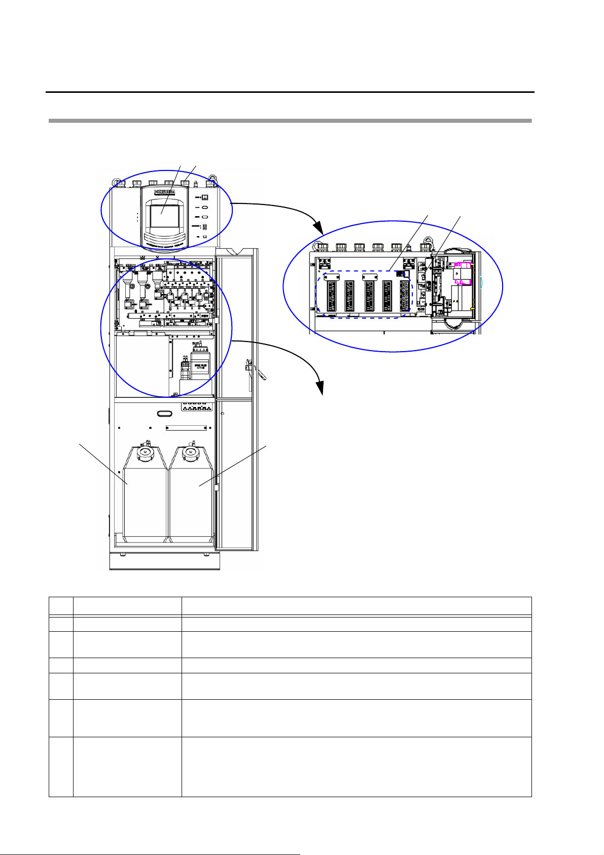
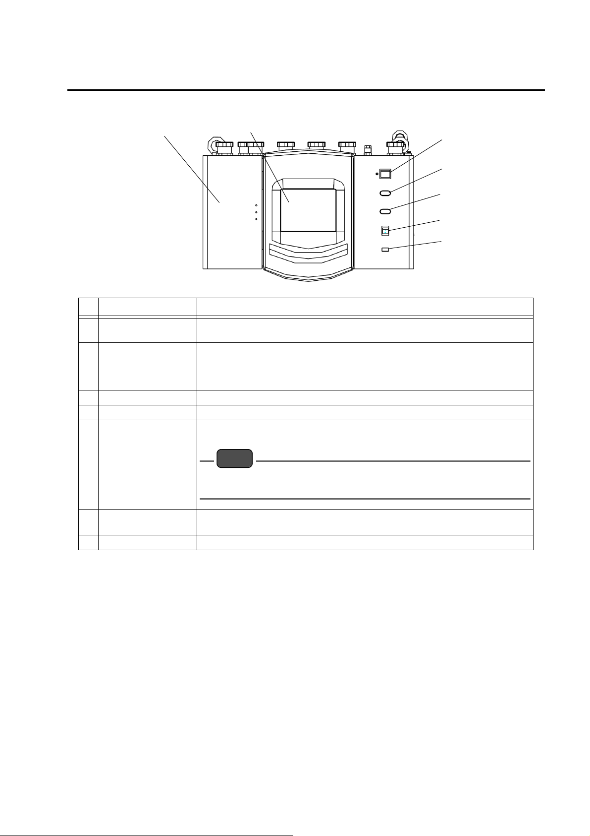
Names of each part
Analyzer
No. Name Description
1 Operation section Refer to “ Operation section” (page 5).
Electrical wiring service
2
entrance
3 Input/output terminal Power supply cable and signal lines are brought into the equipment here.
Main power switch
4
(Ground fault interrupter)
5 Waste liquid tank
6 Pure water tank
A service entrance for electrical wiring.
Turns ON/OFF the power to the equipment.
The amount of waste liquid is approximately 17 L per month. Includes alarm output
contact terminals to activate a “Full Drain Tank” alarm when the tank reaches full capacity.
Tank capacity is 20 L. Check level in the tank and dispose of waste liquid as necessary.
Storage capacity is approximately 20 L of pure water. Amount of pure water
consumed is approximately 40 L per month (depending on measurement range).
Includes alarm output contact terminals to activate a “Lack Blank” alarm when the
amount of pure water remaining is insufficient (not needed for units that use tap water
for the water supply or for units with built-in pure water unit).
2
Before Using the Product
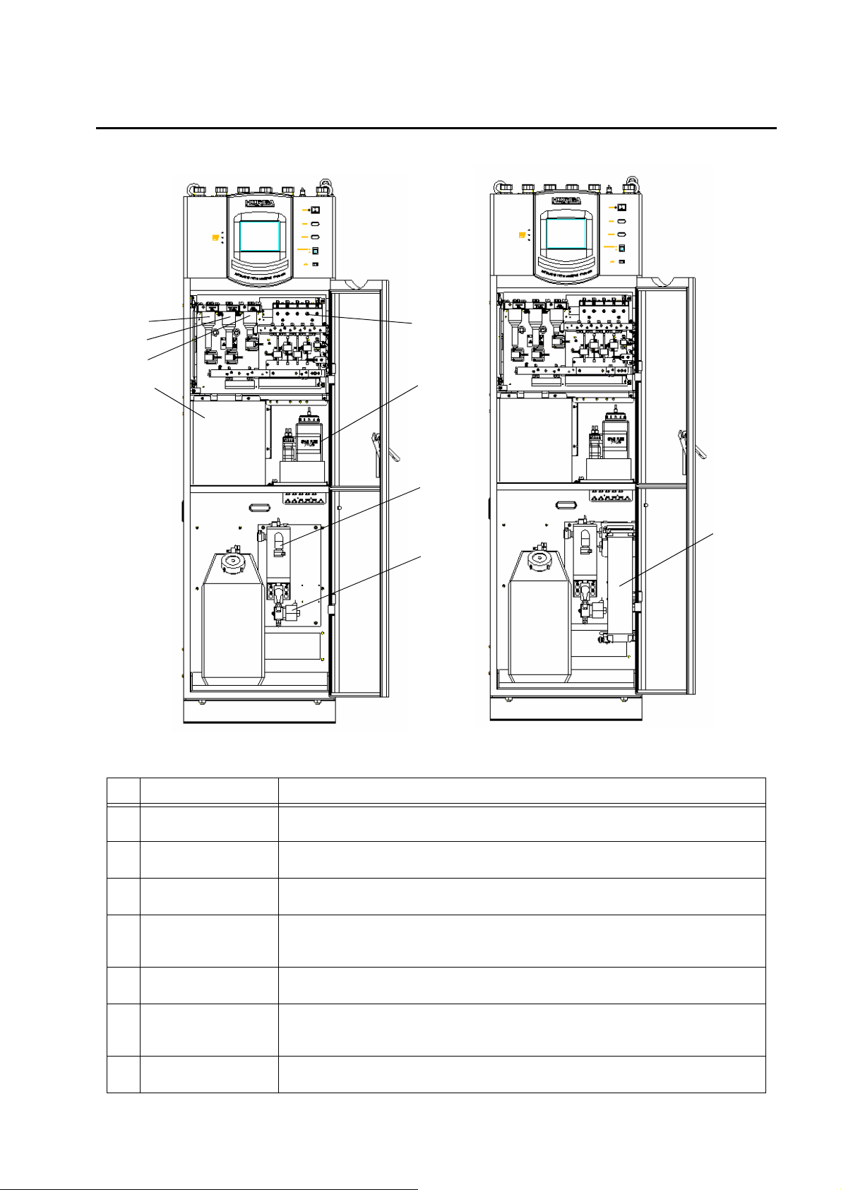
[For the built in pure water cartridge]
[Pure water supply from customer]
13
14
15
7
10
12
11
8
9
No. Name Description3
7 Dilution tube
Pure water
8
measurement tube
Cell measurement
9
tube
10 Analyzer
Reagent metering
11
section
12 Reagent bottle
13 Sub tank(Pure water)
Measures sample solution and diluted sample solution.
The sample solution is diluted with pure water according to the sample concentration.
Measures pure water.
Measures the amount of sample required for measurement and supplies the sample
to the analyzer.
Performs mixing of sample and reagent, heating, ultraviolet irradiation, agitation, and
absorbance measurement.
Measurement cells for total phosphorus and total nitrogen have been integrated.
Measures the amount of each reagent to be injected.
Stores reagent A, B, C, D, E, F and span solution. Each solution can be stored for
approximately one month. An alarm is enabled via external contact terminals when
the amount of a reagent remaining is insufficient.
It is a tank for save pure water.
When a residual quantity decreases, equipment automatically supply pure water.
3

Before Using the Product
No. Name Description3
Solenoid valve(pure
14
water supply)
15 Pure water cartridge
It is an solenoid valve for control of pure water supply.
In the case of specifications with built in pure water cartridge, it is attached.
Pure water necessary for the measurement is purified when you supplies tap water.
Can use it between six months from one year.
4
Operation section
7
2
3
6
5
4
1
Note
No. Name Description
1 Printer door
2 Touch panel
3 Power switch Turns power on and off to the operation section.
4 Alarm indicator Will light up when an alarm occurs.
The printer and its paper, and an automatic printer-paper spooling unit are housed
behind this door.
Displays measurement results, including measurement values, time, and
measurement point, condition settings, operating guidance for maintenance/
adjustment, alarm description, and function key guidance. Can be operated directly
from the screen.
Will light up when internal measurement instrument information is being stored on
an external memory device.
Before Using the Product
5 Access indicator
Do NOT turn power off while the access indicator is illuminated. This could
corrupt data contained on the CF card.
6 Maintenance switch
7 USB port Insertion slot for USB memory devices.
Use this switch when performing maintenance on the equipment. When this switch
is ON, the “Maintenance” contact is output.
5
Before Using the Product
Note
1
2
3
4
5
6
7
8
1
2
3
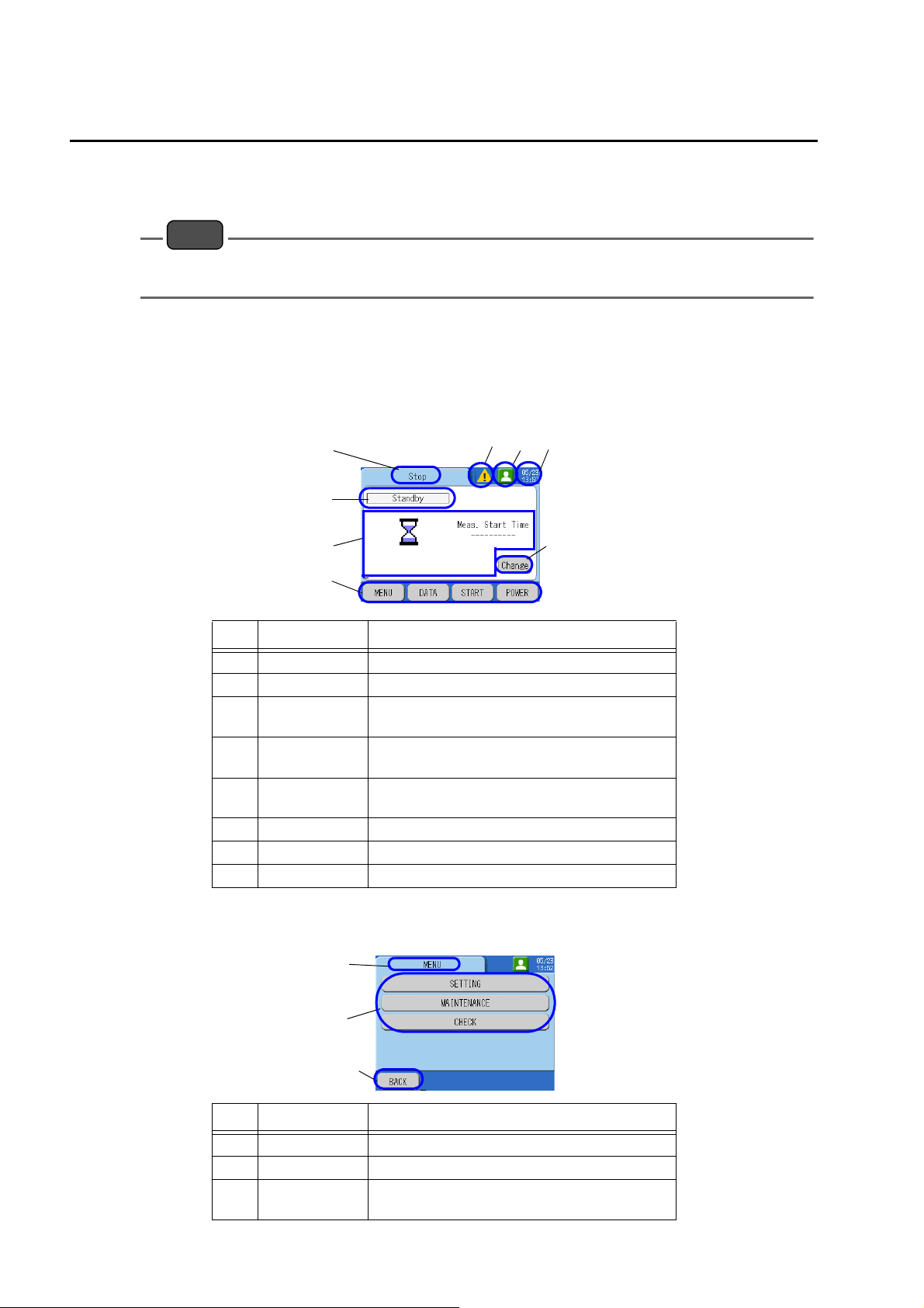
Display
A typical screen example will be used to explain the content displayed on the screen.
The display is a touch panel device. Do not operate the touch panel using the tip of your finger nail or
a tool with a sharp edge, or with wet hands.
Screen example
Display shows readings of measured parameters
This is the main screen that is initially displayed when the power is turned ON.
No. Description Details
1 Screen title Preprocess, MEAS., SETTING, LOG DATA, etc.
2 Component Displays currently active items.
Details of
3
display item
Operation
4
buttons
Equipment
5
status
6 Authority Displays the authority of the operator.
7 Clock display Displays the time.
8 Change Displays previous values.
Displays measurement values, etc.
Switches displays, etc.
Displays whether an alarm has been activated.
Screen when an operating button has been pressed
No. Description Details
1 Screen title MENU, DATA, START, STOP etc.
2 Selection items Displays available options.
Operation
3
buttons
Switches displays, etc.
6
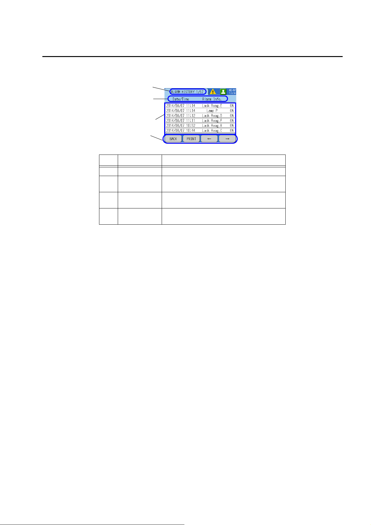
Display details of the selected item
1
2
3
4
Screen will show details of each item.
No. Description Details
1 Screen title ALARM HISTORY, etc.
Description of
2
table contents
Details of
3
display item
Operation
4
buttons
Shows the currently displayed item.
Shows details of display items.
Switches displays, etc.
Before Using the Product
7
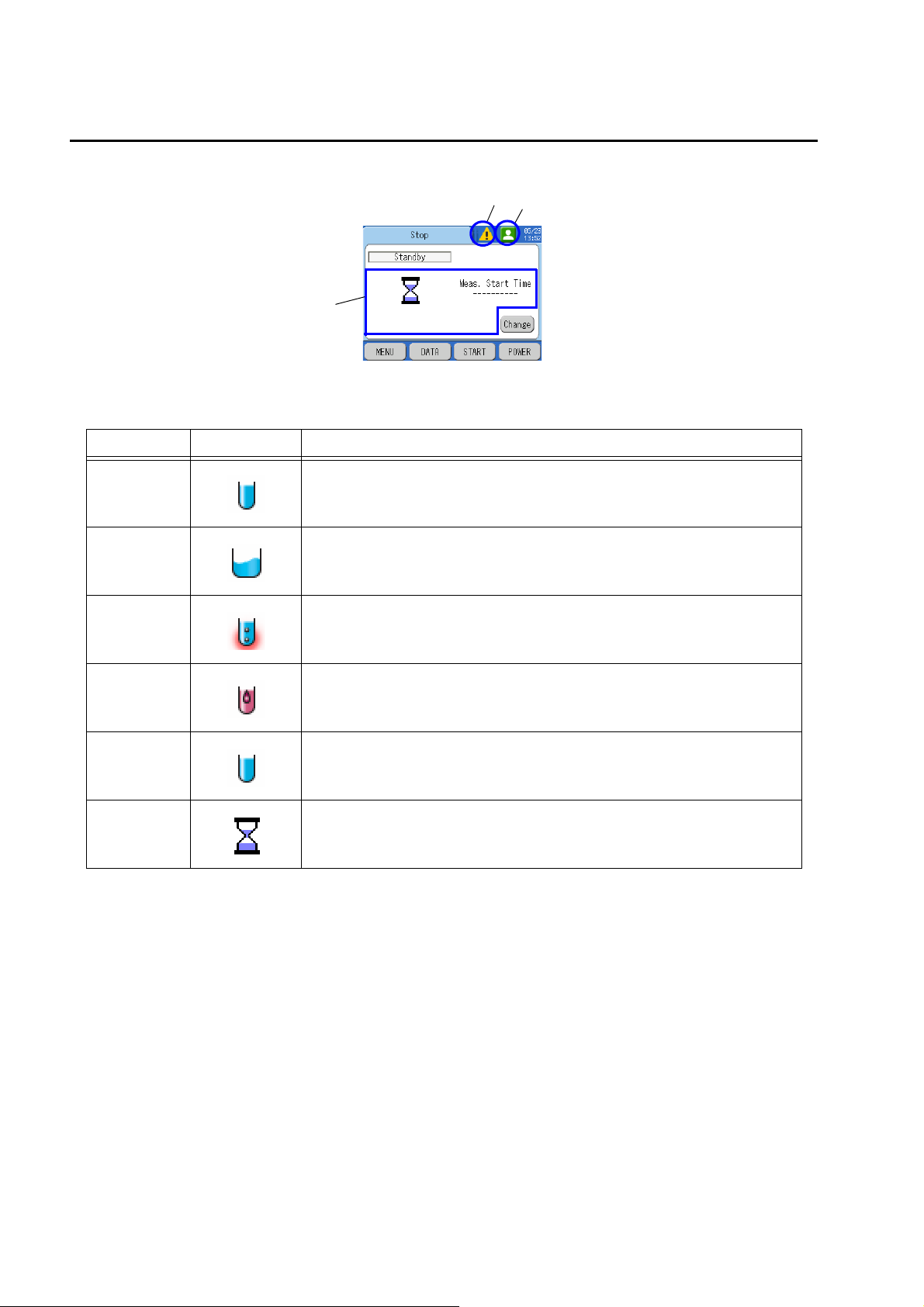
Before Using the Product
A
B
C
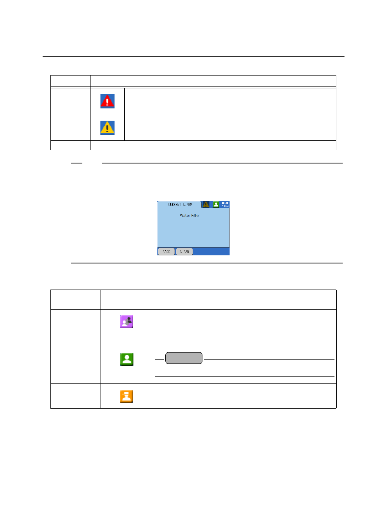
Description of icons
A: Description of the display item icons
Item Icon Description
Pre-processing Preparation prior to start of measurement.
Sampling
Dissolution
Measurement Reagents are added and TP and TN measurements are performed.
Cleaning The dissolution sections are cleaned.
Standby
The sample, pure water, and reagents are measured and injected into the
dissolution sections.
Solutions are exposed to ultraviolet light and heated to cause dissolution of the
compounds in the sample.
Measurements are complete and the unit remains on standby until the next
measurement is started.
8
Before Using the Product
Tip
Reference
B: Description of equipment status icons
Item Icon Description
Critical
(red)
Alarm
activated
Minor
(yellow)
No alarm No display No alarm is activated.
Press the icon to display the currently activated alarms.
To cancel an alarm, take corrective action according to the nature of the alarm and press [CLEAR] on
the screen. For details on corrective actions, refer to “ Cause and corrective action for alarms” (page
218).
An alarm is activated. For details on how to check past alarm, refer to
“ [DATA] - [ALARM HISTORY]” (page 147).
C: Description of the Authority icons
Item
(Mode)
General user Normal measurements can be performed.
Power user
Administrator
Icon Description
Settings for measurement, calibration, and other items can be
performed. To log in, the user must enter a password.
“ AUTHORITY SET” (page 103)
Used while operation is under control of the manufacturer. Customer
operation is not permitted.
9
Before Using the Product
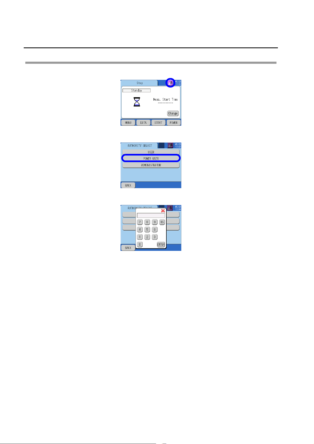
How to change authority
1. Press the icon.
2. Press the relevant authority button.
3. Enter your password and press [ENTER].
10
Connection
Contact
output
Power
Maintenance
Contact
output
Contact
output
Contact
output
Contact
input
Contact
input
Analog output
Analog input
(G)
(+)
()
(G)
(G)
(G)
(G)
(+)
()
(+)
()
(+)
()
(+)
()
(+)
(G)
(G)
(G)
(G)
()
(+)
()
(+)
()
(+)
()
()
(+)
(+)
(G)
(G)
(G)
(G)
(G)
Contact
output
Contact
output
Contact
input
Contact
input
Analog input
Analog output
(G)
(G)
(G)
(G)
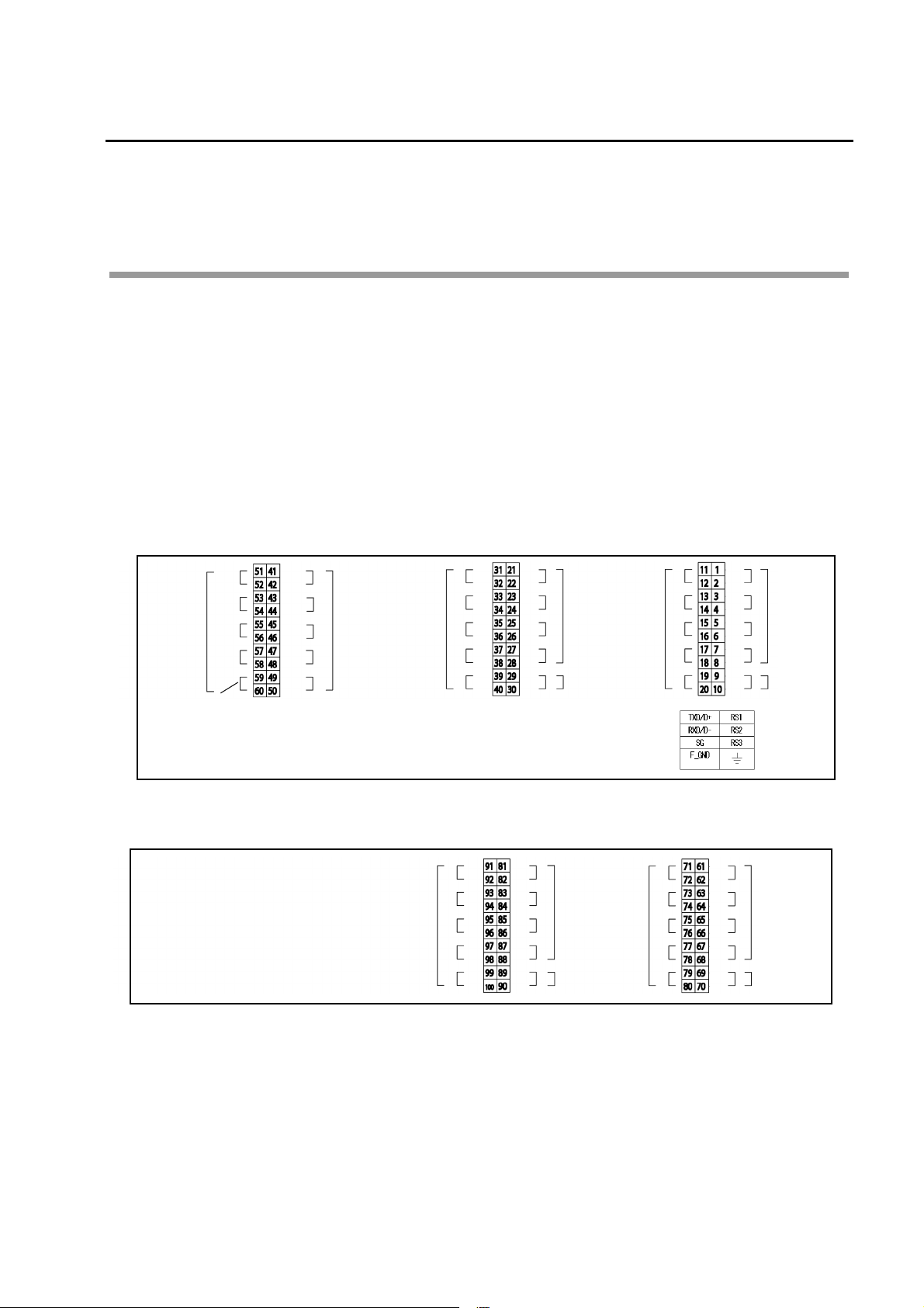
Signal wiring
External input/output
The input/output terminal connection diagram for this equipment is shown below.
The screw connection terminals inside the operation panel are used for the input/output
terminals.
Connect the signal lines according to the signal table.
Use a 2-core shielded cable for the current output signal line. Ground the shielded side to
the receiving side.
For noise protection, connect the surge absorber or noise killer in parallel with the contact
output signal lines.
Input/output terminal (standard: 1-point meter specification)
Connection
Input/output terminal (option: 3-component/2-point meter specification)
11
Connection
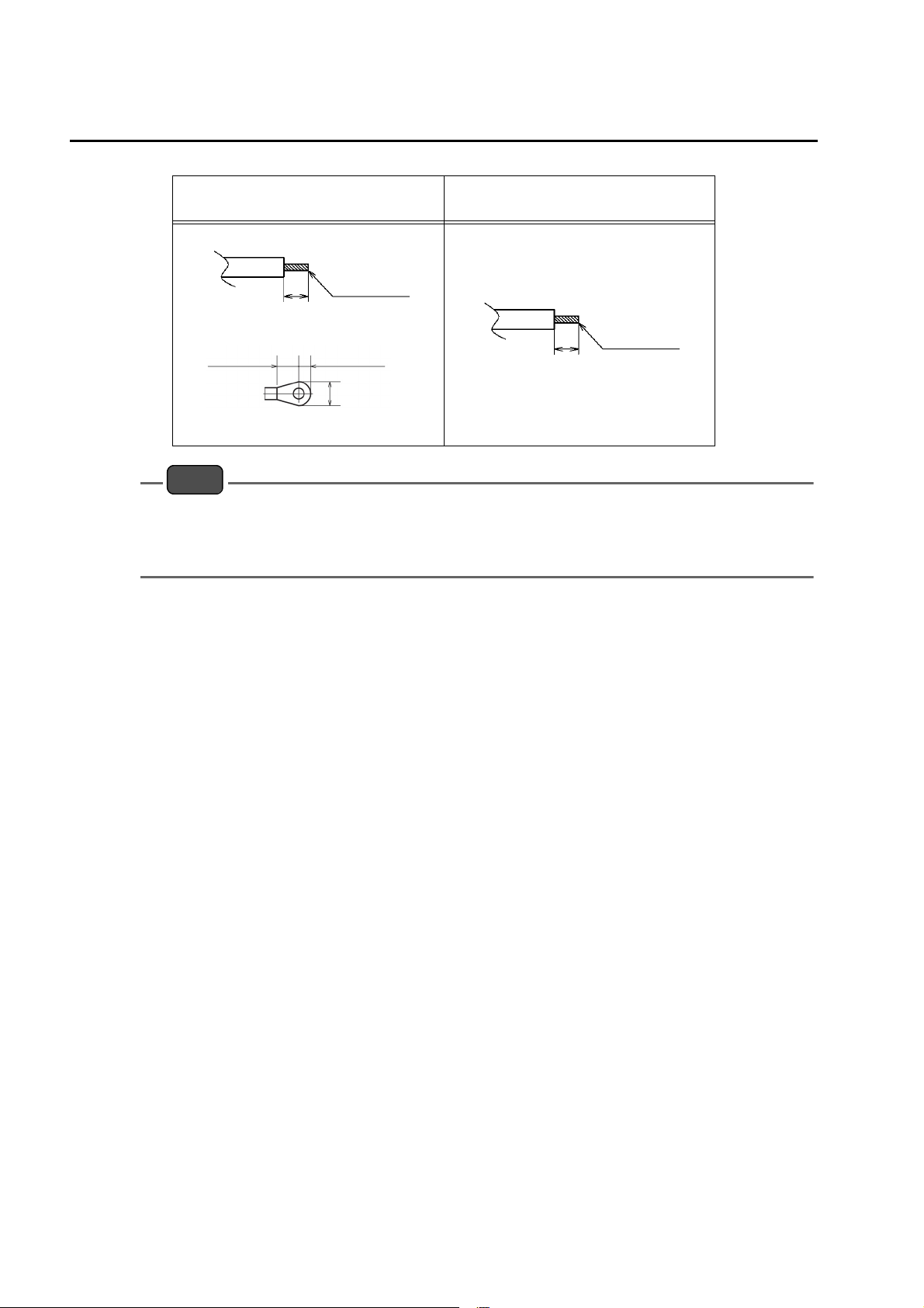
Note
0.75 mm2 to 2.5 mm
2
(AWG18 to 14)
7 mm
Signal line terminal processing
5.2 mm (max.)
4 mm (max.)
7 mm (max.)
Applicable terminal
0.14 mm2 to 2.5 mm
2
(AWG26 to 14)
7 mm
Signal line terminal processing
Perform terminal processing for the signal lines as illustrated below.
For analog input/output and
contact input/output
Do not apply any load exceeding the maximum rating to each terminal. It could cause
For RS communication
malfunction.
Do not connect the power cable to the signal wiring section. It could cause malfunction of the
equipment.
12

Analog output
In this equipment, the measurement values are output via the analog current/voltage output
terminals.
There are four analog output lines as standard. For output, select the desired four
components from the following five.
The values are output in accordance with the specified full-scale value.
Measurement item
Standard specification
Connection
Measurement
item
TP Conc. L1 Outputs the TP concentration for L1
TN Conc. L1 Outputs the TN concentration for L1
TP Load L1 Outputs the TP load for L1
TN Load L1 Outputs the TN load for L1
Flow L1 Outputs the L1 flow rate
No allocation -
Description
Only available for 3-component specification
Measurement item Description
COD Conc. L1 Outputs the COD concentration for L1
COD Conc-sec.L1
COD Load L1 Outputs the COD load for L1
Outputs the COD instantaneous
concentration for L1
Only available for 2-point meter specification
Measurement item Description
TP Conc. L2 Outputs the TP concentration for L2
TN Conc. L2 Outputs the TN concentration for L2
TP Load L2 Outputs the TP load for L2
TN Load L2 Outputs the TN load for L2
Flow L2 Outputs the L2 flow rate
COD Conc. L2 Not used
COD Conc-sec.L2 Not used
COD Load L2 Not used
13

Connection
Measurement item and analog output range
Example of 4 mA to 20 mA output
Measurement
item
TP Conc. L1 10 mg/L 0 mg/L 10 mg/L
Range 4 mA output 20 mA output
Example of 0 mA to 16 mA output
Measurement
item
TP Conc. L1 10 mg/L 0 mg/L 10 mg/L
Range 0 mA output 16 mA output
14
 Loading...