

HORIBA OM-51 Installation Manual

For more information, please contact us:
ExpotechUSA
10700 Rockley Road
Houston, Texas 77099
USA
281-496-0900 [voice]
281-496-0400 [fax]
E-mail: sales@expotechusa.com
Website: www.ExpotechUSA.com

Preface
Thank you for purchasing the ES-51 conductivity meter.
This meter is designed with a compact body that can be held in one hand and
features a water-resistant construction Note 1. It has a large-sized LCD display,
which enables to use the varied functions by simple operations, and especially
will be convenient to use on-location.
Carefully read this manual before using the meter.
Note 1: The water-resistant construction of this meter conforms to IP-67 of IEC
529, entitled “Water resistant testing and protection against penetration by solid
matter for electrical machinery and equipment.” To maintain the water-resistant
construction of this meter, follow the instructions in this manual when using the
meter.
IP-67 standards
・ Dust does not get into internal parts.
・ Water does not flow into internal parts when the meter is submerged 1 m
below the surface
between the water and the device of 5 ℃ or less.
Warranty and Responsibility
Your meter is covered by warranty for a period of one (1) year, under
normal use. Although unlikely, if any trouble attributable to us should occur
during this period, necessary exchange or repairs shall be conducted by us,
free of charge. The warranty does not cover the f ollowing:
of the water for 30 minutes, at a temperature differential
・ Any trouble or damage attributable to actions or conditions specifically
mentioned to be avoided in the operation manuals
・ Any trouble or damage attributable to use of the meter in ways or for
purposes other than those described in the operation manuals
・ If any repairs renovations, disas se mb ly, etc. ar e p er f or me d o n t hi s m e te r b y
any party other than us or a party authorized by us
・ Any alteration to the external appearance of this meter attributable to
scratches, dirt, etc. occurring through normal use
・ Wear and tear to parts, the exchange of accessories, or the use of any parts
not specified by us
We also shall not be liable for any damages resulting from any malfunctions
of this product, any erasure of data, or any other uses of this product.

■ CE Marking
This product is in conformity with the following directives and
standards:
Directives:The EMC Directives 89/336/EEC
The Electrical Product Safety Directive 73/23/EEC
Standards: EN61326: 1997+A1:1998
(EMISSION: Class B, IMMUNITY Category: Minimum Require-
ment)
EN61010-1: 2001
Installation Environment
This product is designed for the following environment.
- Pollution degree 2
- Measurement category Ⅰ
Precautions for use
WARNING:Do Not use the equipment for measurements within
measurement categories
Ⅱ , Ⅲ and Ⅳ .
■ FCC Warning
This equipment has been tested and found to comply withthe limits
for a Class A digital device, pursuant to part 15 of the FCC Rules.
These limits are designed to provide reasonable protection against
harmful interference when the equipment is operated in a
commercial environment.
This equipment generates, uses, and can radiate radio frequency
energy and, if not installed and used in accordance with the
instruction manual, may cause harmful interference to radio
communications.
Operation of this equipment in a residential area is likely to cause
harmful interference in which case the user will be
required to correct the interference at his own expense.
I
Precautions for use
■ Type and Definition of Signal Words
For the safety use, the meter is equipped with the Warning Labels
to alert every operator and user to the possible risk and danger.
Before using understanding each message.
The meaning of signal words are as follows:
(WARNING)
This indicates an potentially hazardous situation which,
if not avoided, will result in death or serious injury.
(CAUTION)
This indicates a potentially hazardous situation which, if
not avoided, may result in minor or moderate injury. It
may also be used to alert unsafe practices.
■ Safety Precautions
For the safety use, be sure to read the following precautions:
WARNING:
●Do not use any unspecified AC adapters.
Heat or fire may occur to cause fire or accidents.
●Do not disassemble or modify the meter.
Heat or fire may occur to cause fire or accidents.
CAUTION:
●Do not use the serial communication or AC adapter in the place that
may possibly contact with moisture.
It may cause fire, electric shock, or breakage.
●Part of the electrode is made of glass; handle with care not to break it.
II
● Indication
Precautions for use
WARNING
This indicates an potentially hazardous situation which, if not
avoided, will result in death or serious injury.
CAUTION
This indicates a potentially hazardous situation which, if not
avoided, may result in minor or moderate injury. It may also be
used to alert unsafe practices.
This mark indicates the operation requires a special care and
attention.
This mark indicates to which the reader should go for reference.
HINT!
This mark indicates reference information.
III

■ Cautionary Items
● Precautions
●Do not give physical shock to the meter like dropping or hitting.
●Do not immerse the meter into alcohol, organic solvent, strong
acid, strong alkaline, and other similar solutions. The meter
contains ABS resin, acrylic resin, and various rubber products in
its body
●Do not use a hair-dryer for drying the meter. When the meter is
dropped into water or get wet, wipe it using soft cloth.
●Perform the key operation by the fingers, not by the hard object like
metal stick or rod.
●Be careful not to let water into the meter when the electrode connector
is empty or the AC adapter or serial communications cable has been
connected. In those states, the meter is not water-proof
●To disconnect the electrode cable or interface cable, pull them out with
holding the connector part. Do not pull the cable part; it may cause a
breakage.
●Do not remove the battery gasket or twist it.
●When opening the battery case, make sure that no foreign matter is
attached to the battery gasket.
●Do not use any unspecified batteries ; it may cause a breakage.
.
Precautions for use
.
● Location of use and storage
●The place which room temperature is at 0 ℃ to 45 ℃
●The place which relative humidity is under 80% and free from
condensation
Do not use or store the meter at;
●The place of much dust
●The place with strong vibration
●The place with direct sunlight
●The place with corrosive gas generation
●The place near from an air-conditioner
●The place with direct wind
● Move and Transportation of the meter
To transport the meter, use the packaging box at the delivery.
Transportation by any unspecified packing methods may cause a
breakage.
● Disposal
Standard solution used for the calibration must be und er
neutralization before the disposal. As for the disposal of the meter,
treat it as an industrial waste.
IV

CONTENTS
1 Overview of the Meter . . . . . . . . . . . . . . . . . . . . 1
1.1 Package contents........................................................................... 1
1.2 Functions......................................................................................... 3
1.3 Part names ...................................................................................... 6
1.4 Explanation of display.................................................................... 7
1.5 Operation keys................................................................................ 9
1.6 Connecting the electrodes............................................................. 10
1.7 Inserting/replacing the dry-cell batteries ..................................... 12
1.8 Connecting the AC adapter ........................................................... 14
2 Taking Measurements . . . . . . . . . . . . . . . . . . . . 15
2.1 Turning the meter ON/OFF............................................................. 15
2.2 Settings required before measurement........................................ 15
2.3 Measurement modes...................................................................... 16
2.4 Selecting the measurement modes .............................................. 18
2.5 Conductivity measurement ........................................................... 19
3 Functions . . . . . . . . . . . . . . . . . . . . . . . . . . . . . . 27
3.1 Data memory function.................................................................... 27
3.2 Displaying and setting the clock................................................... 30
3.3 Setting modes................................................................................. 32
3.3.1 Entering the Setting mode ............................................................ 32
3.3.2 Display and description ................................................................ 33
3.3.3 Temperature compensation setting .............................................. 34
3.3.4 Auto data storage setting ............................................................. 35
3.3.5 Sample ID# setting ....................................................................... 37
3.3.6 Conductivity unit setting ............................................................... 38
3.3.7 Temperature coefficient setting ................................................... 38
3.3.8 Maintenance mode ....................................................................... 39
4 RS-232C communications . . . . . . . . . . . . . . . . . 49
4.1 Cautions before use....................................................................... 49
4.2 Command list.................................................................................. 51
4.3 On-line operation commands........................................................ 54
ES-51 V

CONTENTS
4.4 Data request commands and responses...................................... 60
4.5 Communication example using the HyperTerminal.................... 69
5 Printer . . . . . . . . . . . . . . . . . . . . . . . . . . . . . . . . . 71
5.1 Connecting the printer................................................................... 71
5.2 Printer setting ................................................................................. 72
5.3 Printer output timing...................................................................... 73
5.4 Printing format................................................................................ 74
5.4.1 When the ENTER key is pressed in the Measurement mode ...... 74
5.4.2 When the manual data memory storage is performed in the
Measurement mode .................................................................................75
5.4.3 When the ENTER key is pressed in the Data Memory Call screen 75
5.4.4 When calibration or check is performed in the Calibration mode . 76
5.4.5 Test printing format in the Maintenance mode ............................. 76
6 Maintenance and Troubleshooting . . . . . . . . . . 77
6.1 Conductivity electrode maintenance............................................ 78
6.2 Troubleshooting ............................................................................. 79
6.2.1 Error message chart ..................................................................... 79
6.2.2 More troubleshooting .................................................................... 84
7 Reference . . . . . . . . . . . . . . . . . . . . . . . . . . . . . . 91
7.1 Conductivity measurement............................................................ 92
7.2 Specifications ................................................................................. 99
7.3 Default settings............................................................................... 101
7.4 Operation flowcharts...................................................................... 102
7.5 Pin layout of special cables......................................................... 103
7.5.1 RS-232C communications cable ................................................ 103
7.5.2 Cable for CITIZEN printer ............................................................. 103
7.5.3 Cable for SEIKO printer ................................................................ 103
7.6 Spare and optional parts.............................................................. 104
7.6.1 Spare parts list ........................................................................... 104
7.6.2 Options ......................................................................................... 105
VI HORIBA
1 Overview of the Meter
This chapter explains the part names, how to connect
the electrodes, how to replace the batter
precautions when using the meter.
1.1 Package contents
1 Overview of the Meter
1.1 Package contents
ies, and
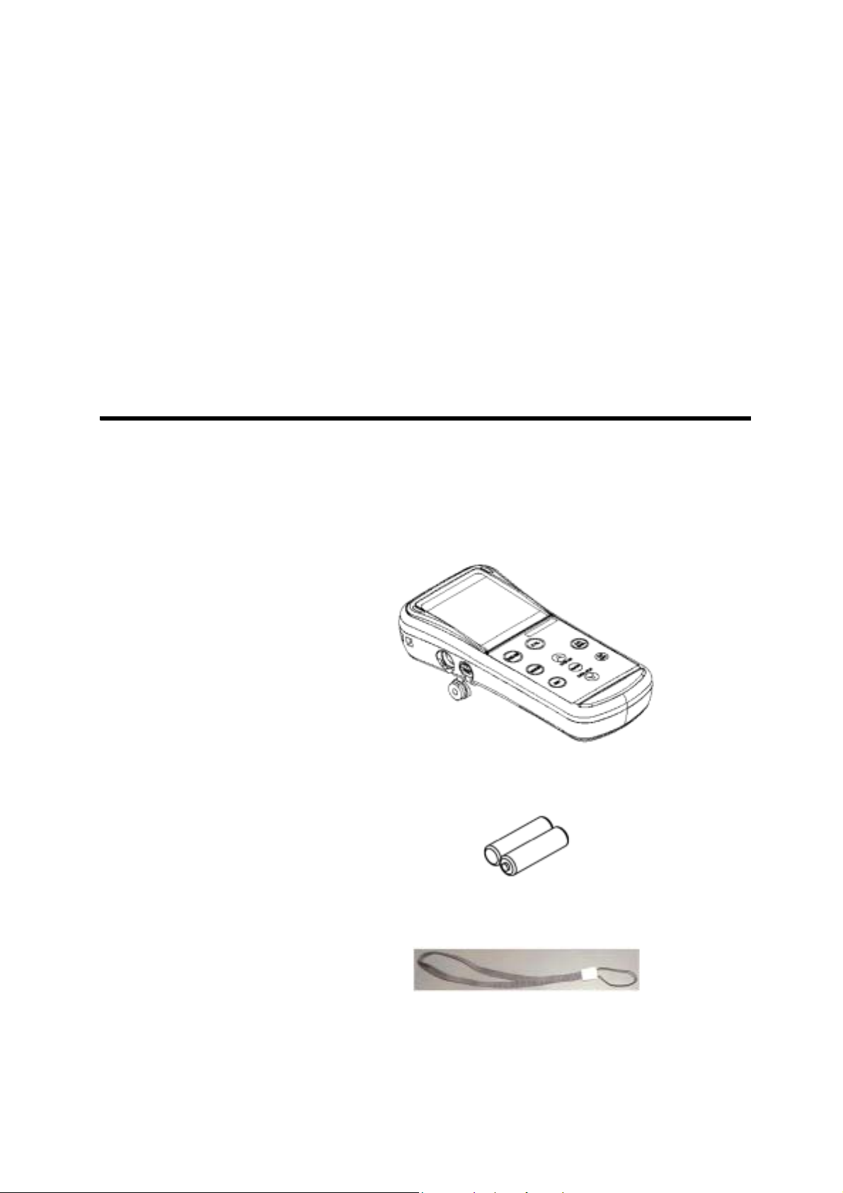
The following items are shipped with each HORIBA
conductivity meter package.
Meter (main unit) 1 unit
Dry-cell batteries 2 pcs.
Strap 1 pc
ES-51 1
1 Overview of the Meter
1.1 Package contents
Soft case 1 pc
Operation manual 1 book
To take measurements, you will need electrode(s).
Refer to “7.6 Spare and optional parts” page 104 when
purchasing the electrode(s).
2HORIBA
1.2 Functions
The ES-51 features the following functions.
● Measurement items
1 Overview of the Meter
1.2 Functions
Items
Conductivity Conductivity electrode,
Salinity
Resistivity
Temperature
Required electrode/
standard solution
Conductivity standard
solution
−
● Functions
An overview of the functions found on HORIBA the
ES-51 is shown below.
Function Explanation
Data memory Stores the data of measured values and
temperature to the memory (max. 300
items)
Page
No.
page
27
Clock Displays the time on the screen and
recorded data.
Auto Power
OFF
RS-232C
communication
Printer output Prints the contents of the memory. page
AC adapter
connection
Automatically turns off power if no operation
is made
Enables the communication with a computer
using RS-232C.
The meter can be AC-powered. page
after 30 minutes.
page
27
page
44
page
49
71
14
ES-51 3
1 Overview of the Meter
1.2 Functions
● Setting Items
Function Explanation
Page
No.
Temperature
compensation
Toggles between Automatic Temperature
Compensation (ATC) mode that measures
page
34
the sample temperature using the
temperature sensor built-in the electrode and
Manual Temperature Compensation (MTC)
mode that uses user-specified temperature.
Auto data
memory
Stores data automatically at an interval of 2
sec. to 24 hours.
page
35
Sample ID Registration of sample ID page
37
COND unit Toggles between S/m and S/cm. page
38
COND
temperature
Automatically or manually sets temperature
coefficient for a sample.
page
38
coefficient
RS-232C communications and the printer cannot be
used simultaneously.
4HORIBA
● Functions in Maintenance mode
1 Overview of the Meter
1.2 Functions
Function Explanation
LCD check Enables check for whether or not all LCD
.
Battery voltage
segments are displayed
Enables simple check of battery voltage. page
check
Temperature
Carries out temperature calibration. page
zero adjustment
Auto Power OFF Sets the function that automatically turns the
power OFF if no keys are touched 30
minutes.
Remaining data
Displays the remaining memory. page
memory
Data memory
Deletes data in memory. page
clear
Page
No.
page
41
42
43
page
44
45
45
Initializing
settings
Initializes all settings to the default values. page
46
Printing test Conducts a printing test. page
47
ES-51 5
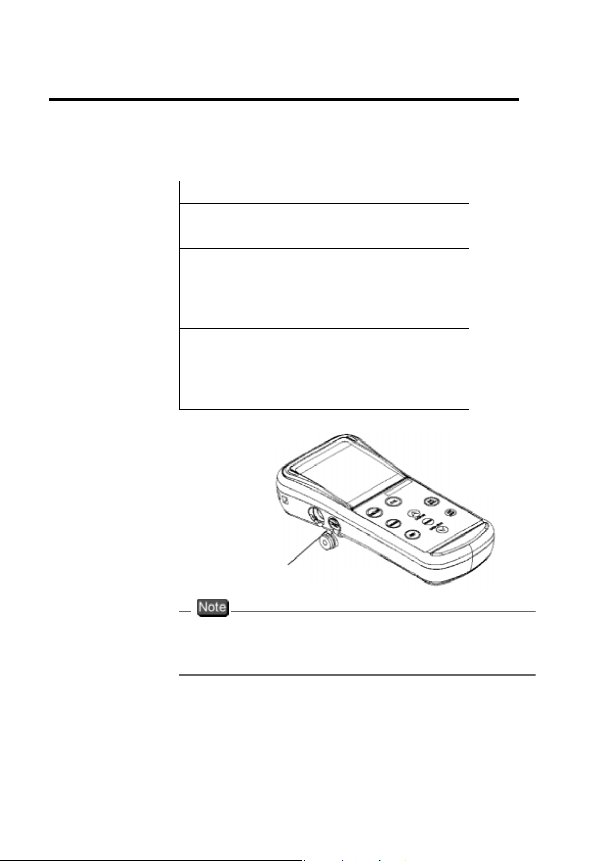
1 Overview of the Meter
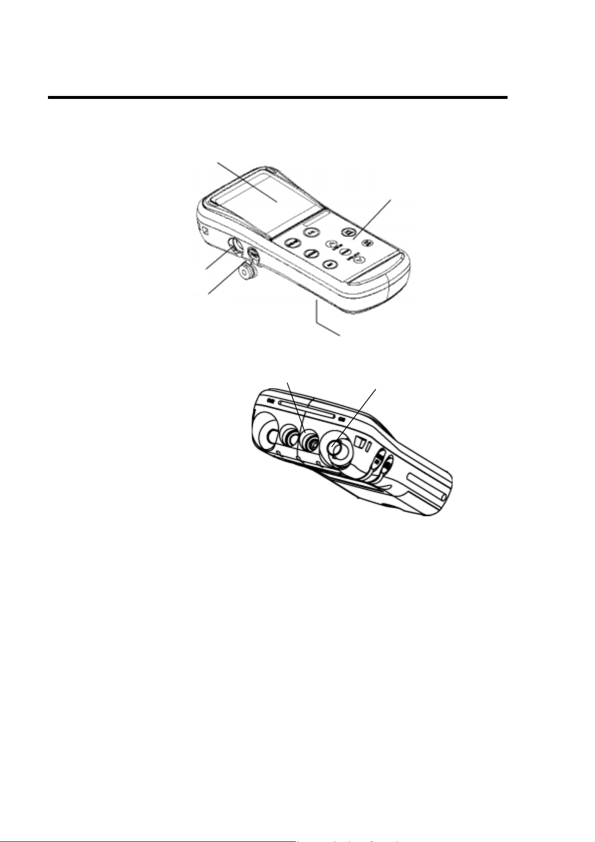
1.3 Part names
1.3 Part names
The ES-51, conductivity meter has the following parts:
Serial communication
port
Display
Keys
AC connector
Temperature connector
Dry-cell battery holder
Electrode connector
6HORIBA
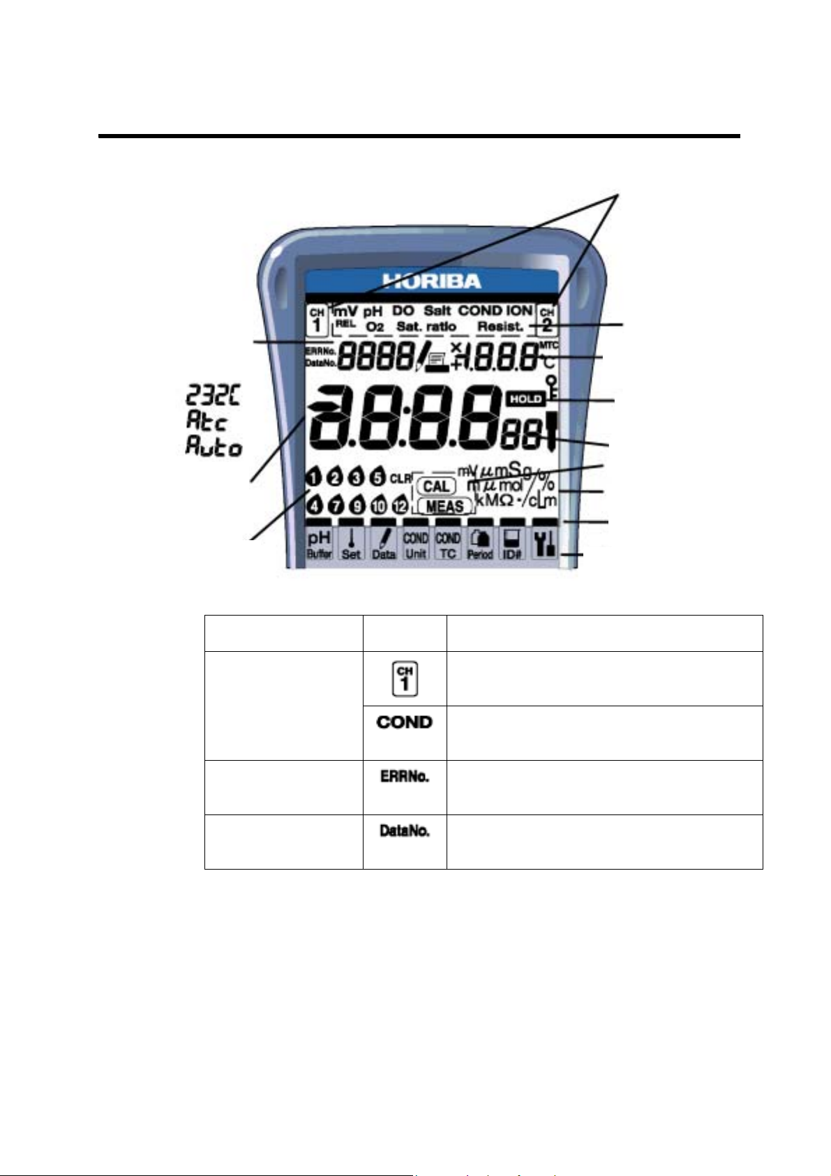
1.4 Explanation of display
1 Overview of the Meter
1.4 Explanation of display
Input channel
Error No.,
Data No.
Year,
Status display
Measurement
data, hour and
minute
Calibration
history
Part name Display Contents
Input channel Input channel 1
Measurement
item
Temperature,
month and day
HOLD
Second
Meter mode
Measurement unit
Cursor for selecting
setting modes
Setting modes differ
according to model
Displayed when measuring
conductivity
Error No. Displayed when an error is
generated
Data No. Displayed when the data number
has been set.
ES-51 7
1 Overview of the Meter
1.4 Explanation of display
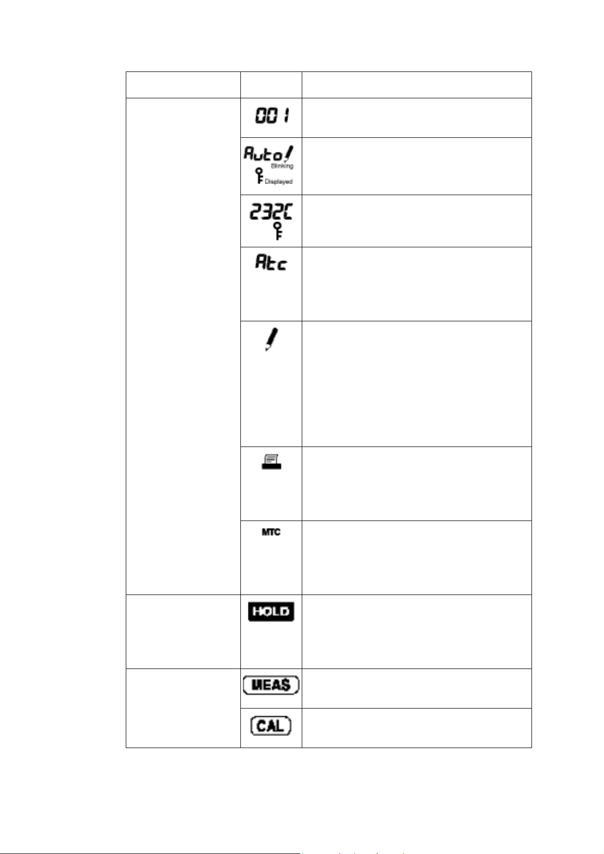
Part name Display Contents
Status display
−
−
−
Shows error number and data
number.
Displayed when AUTO data
memory is being performed.
Displayed when the serial
communication is active.
Displayed when temperature
compensation function or
automatic temperature
compensation has been set.
Displayed during data memory
function (for 3 sec.).
Displayed while data in memory is
being called up and when manual
data memory is being called up, or
blinks when automatic data
memory is being called up.
Displayed when a printer is
connected. (
Sometimes displayed
when a computer is connected
depending on the computer.)
Displayed during manual
temperature compensation
.
Not displayed during automatic
temperature compensation
.
HOLD Displayed while the data is held
(HOLD status).
Blinks during measurement or
calibration.
Meter mode Displayed when in Measurement
mode
.
Displayed when in Calibration
mode.
8HORIBA
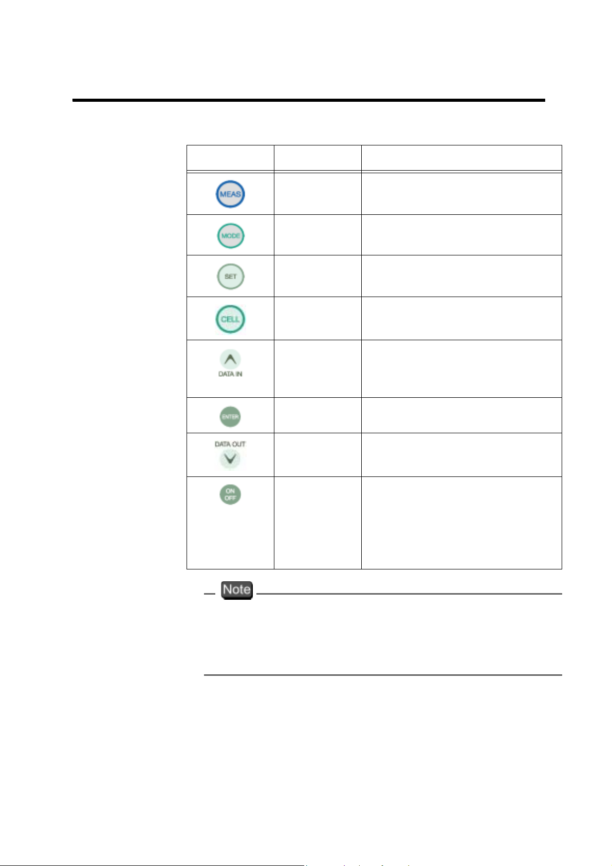
1.5 Operation keys
This section describes the functions of the keys.
1 Overview of the Meter
1.5 Operation keys
Name Description
MEAS key Returns to the Measurement
mode. Starts measurement.
MODE key Selects measurement item.
SET key Selects setting item.
CELL key Enters the Cell Constant
Setting mode.
UP key Executes the data memory
function.
value
ENTER key Establishes the setting.
DOWN key Calls up data memory.
Decreases numerical value.
ON/OFF
key
The automatic power-off function is a default setting for
this meter. The power is automatically turned OFF if no
operation is performed
30 minutes.
Turns ON/OFF the power.
This
after pressed for one second
to prevent accidental
operation.
after a period of approximately
Increases numerical
.
key takes effect only
ES-51 9
1 Overview of the Meter
1.6 Connecting the electrodes
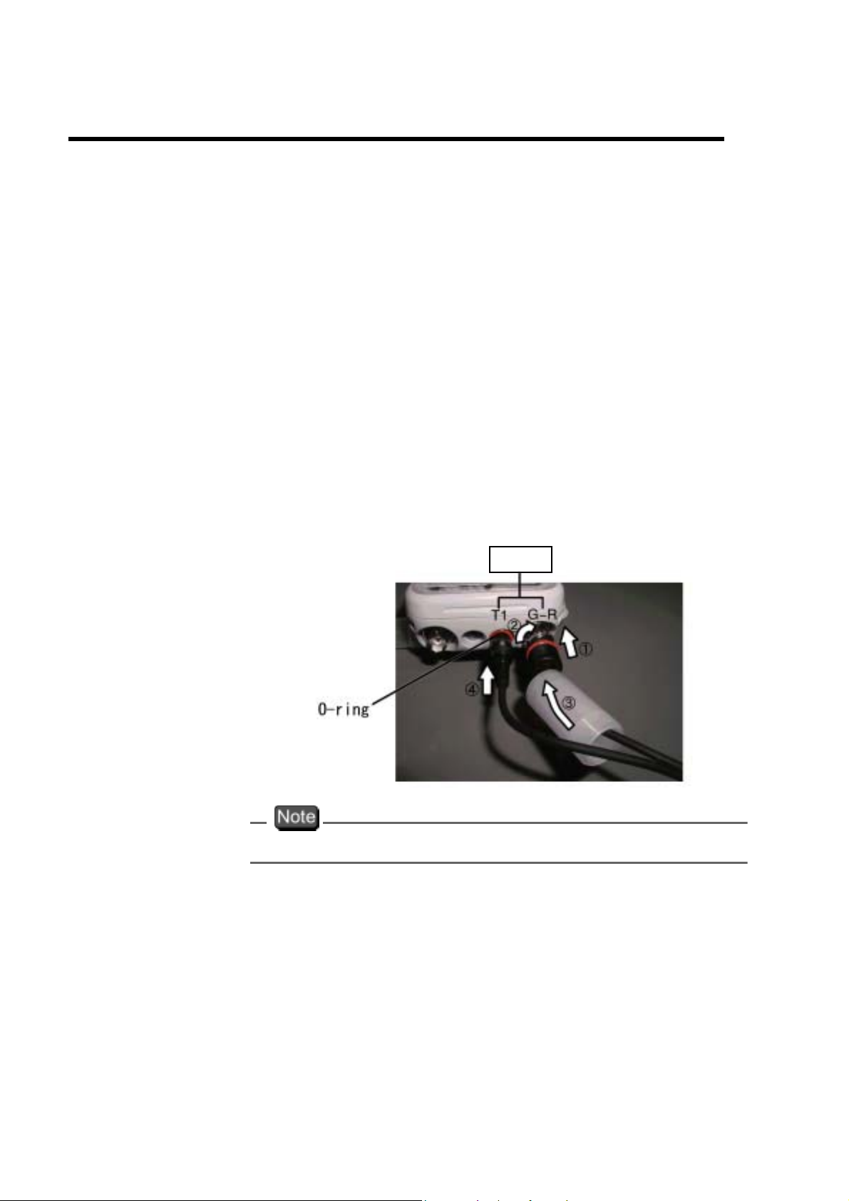
1.6 Connecting the electrodes
Connect the electrodes to the conductivity meter using
the following
that no water or dirt come in contact with the connector
during connection procedures.
・Electrode connector: Conductivity electrode
・Temperature connector: Temperature electrode
procedures. Use special care to ensure
● Electrode connector (G-R electrode)
1. Insert the electrode connector, making sure to
align the connector grooves with the pins in the
connector port on the main unit (see photo, ① ).
Do not push the electrode with undue force
when the pins are not properly aligned.
COND electrode
Do not perform this step with wet or uncleaned hands.
CH1
2. Push the electrode connector into the connector
port while turning it clockwise, following the
grooves (see photo, ① and ② ).
10 HORIBA
3. Push the connector cover over the connector
(see photo, ③ ), being careful to push it straight
on without turning it.
The meter will be waterproof only if this cover is placed
properly over the connector.
● Temperature connector
1. Insert the temperature connector into the jack on
the main unit until the O-ring on the electrode
can
not be seen at all (see photo, ④ ).
1 Overview of the Meter
1.6 Connecting the electrodes
The meter will not be waterproof if the electrode is not
inserted properly.
When the temperature electrode is not connected (or is
connected improperly), the
compensation (ATC), will be 25°C.
automatic temperature
ES-51 11
1 Overview of the Meter
1.7 Inserting/replacing the dry-cell batteries
1.7 Inserting/replacing the dry-cell batteries
The dry-cell batteries are not placed in the meter before
shipping. To insert the batteries, follow the procedure
below
Note that if “ERR 2” appears on the display while using
the meter,
teries is running low. When this occurs, replace the bat-
teries promptly.
Dry-cell battery type: AA alkaline
・Insert the batteries, paying attention to the orientation
.
it indicates that the charge of the dry-cell bat-
of the battery poles (+ and -).
・Removing the batteries will erase the clock data. To
save the clock data, remove and replace the batteries
while the meter is connected to the AC adapter
separately)
・Replace the batteries only after turning the power
OFF.
・When opening and closing the battery cover, be care-
ful that no water gets inside the meter.
・Check that the rubber packing is not twisted and no
foreign matter is stuck to it. Otherwise the meter may no
longer be waterproof.
The life of the batteries included with the meter may be
short because the batter
check before shipping.
Any saved data will not be lost.
.
ies were used for the operation
(sold
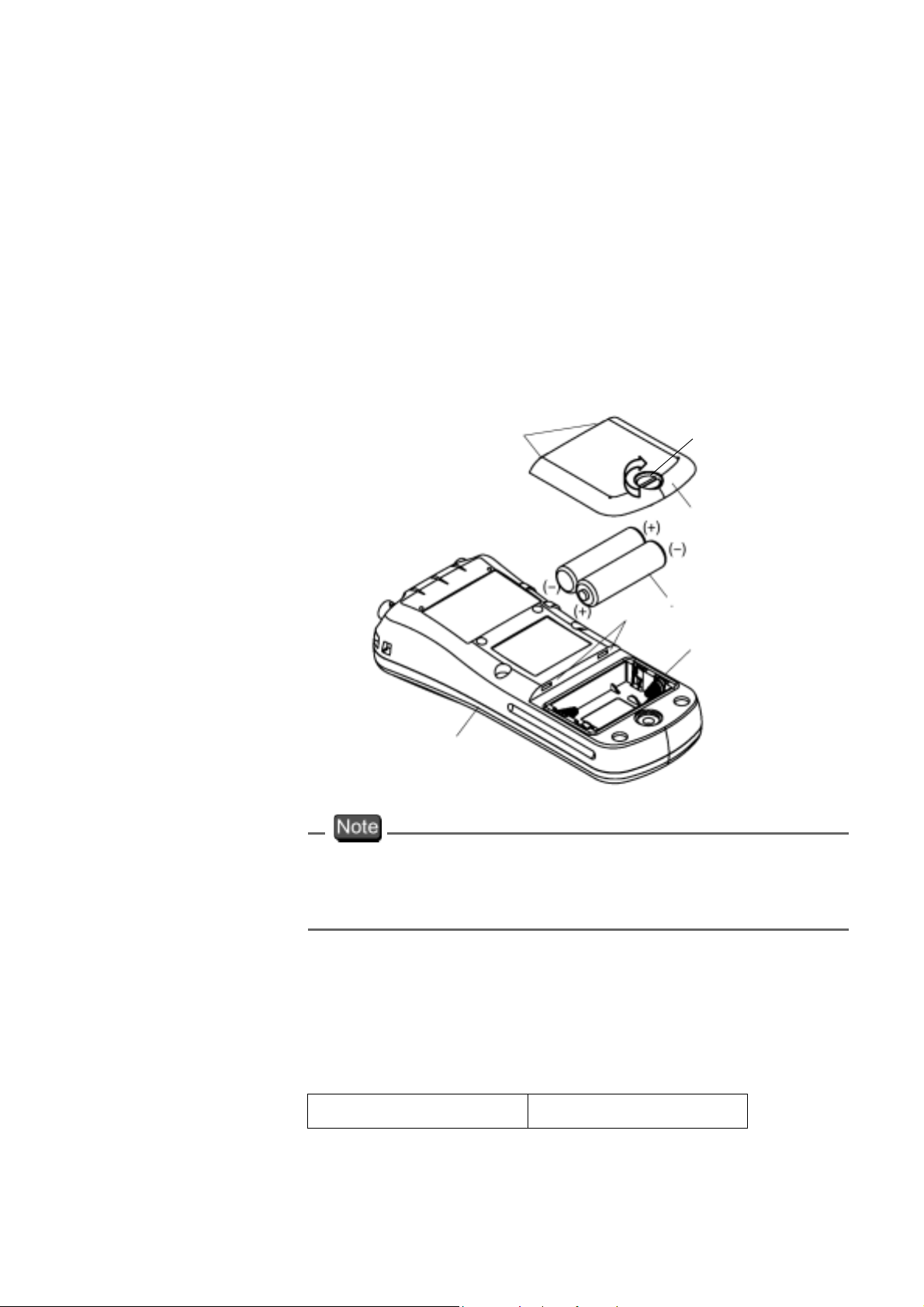
To insert/replace the batteries
1. Loosen the screw of the battery cover by using a
coin or screwdriver, etc. The cover is
constructed so that the stop screw cannot be
completely removed and lost.
2. Pull up the screw, and remove the battery cover
by sliding it out.
12 HORIBA
1 Overview of the Meter
1.7 Inserting/replacing the dry-cell batteries
3. If there are old batteries inside, remove them.
4. Place the new batteries in the meter, verifying
the orientation of the poles (“+” and “-”).
5. Check that the rubber packing is not twisted and
no foreign matter is stuck to it.
6. Insert the edge of the battery cover into the
grooves on the meter, and then tighten the stop
screw.
Edge
Tighten
Grooves
Main unit
Stop screw
Battery cover
Batteries
Rubber packing
Check that the rubber packing is twisted and no foreign
matter is stuck to it. Otherwise the meter may no longer
be waterproof.
Battery life
The table below shows the battery life of alkaline
batteries
during continuous use. The life of manganese
batteries is about a half of the alkaline batteries.
Battery life approx. 100 hours
ES-51 13
1 Overview of the Meter
1.8 Connecting the AC adapter
1.8 Connecting the AC adapter
When using the meter with an AC power supply, use the
designated AC adapter (option).
AC adapter specifications
Supply voltage range 100 - 200 V AC
Frequency range 50/60 Hz
Current rating Max 370 mA
Class2 Power supply
Equipment pro-
tected by double
insulation
Indoor use only
Supply voltage fluc-
tuations allowed up
to
± 10%
.
AC adapter connector
When the AC adapter is connected, the meter is no
longer
waterproof.
Be careful not to let water get into the meter.
14 HORIBA
2 Taking Measurements
This chapter explains how to take basic measurements.
2.1 Turning the meter ON/OFF
Pressing the ON/OFF key turns the power on/off. The
ON/OFF key functions when it is pressed continuously
2 Taking Measurements
2.1 Turning the meter ON/OFF
for about one second to protect against accidental
operation.
2.2 Settings required before measurement
The built-in clock allows you to record the date of
calibration and data memory storage. When using the
meter for the first time, be sure to set this clock.
“3.2 Displaying and setting the clock” page 30
ES-51 15
2 Taking Measurements
2.3 Measurement modes
2.3 Measurement modes
The ES-51, conductivity meter has an Instantaneous
Value Measurement mode and an Auto Hold
Measurement
being measured.
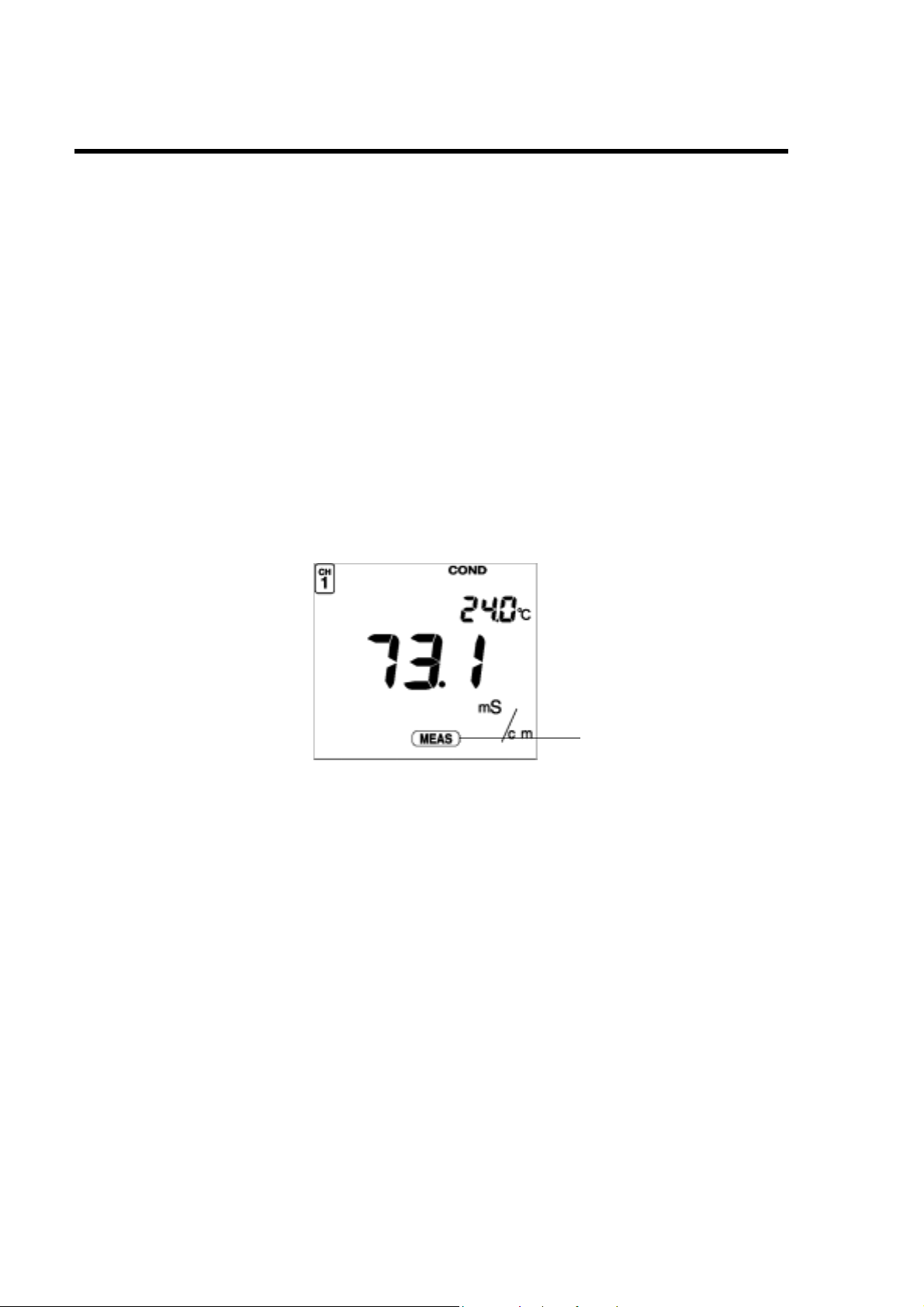
● Instantaneous Value Measurement mode
The ES-51, conductivity meter performs instantaneous
value measurement as the default measurement mode
when the power is first turned ON and when
measurement is cancelled or cleared.
hold
For this reason, the screen displayed when the meter is
in the Instantaneous
the "initial screen" in this manual.
mode for all components of the solution
Value Measurement mode is called
the auto
Displayed
16 HORIBA
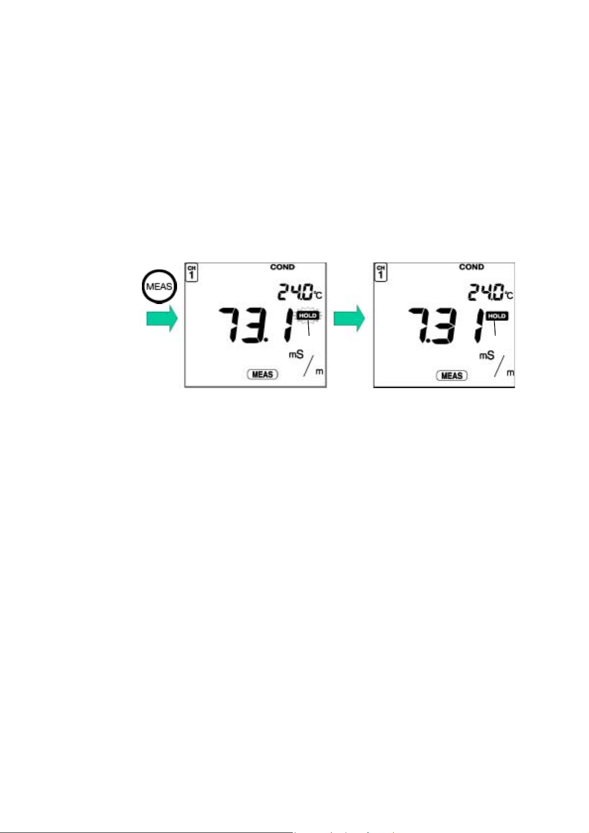
● Auto Hold Measurement mode
Auto Hold Measurement mode maintains the display of
the value measured when the meter automatically
judges that the measured value has stabilized. Press the
2 Taking Measurements
2.3 Measurement modes
MEAS key with the initial screeen
displayed to make
HOLD blink on the display. When the measured value
becomes stable, HOLD will stop blinking and remain
displayed, and the measured value will remain
displayed. To clear the hold status or stabilized value
(when HOLD is blinking), press the MEAS key.
Blinks
Displayed
Criteria for judging stability
Conductivity
measurement
Temperature
measuremen
Within ±3-digit variance after 10
:
seconds
Within ±2ºC variance after 10
:
t
seconds
ES-51 17
2 Taking Measurements
2.4 Selecting the measurement modes
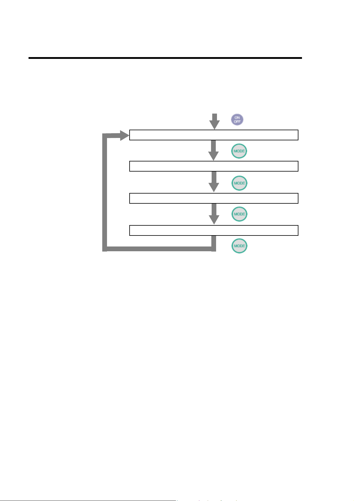
2.4 Selecting the measurement modes
Pressing the MODE key changes the measurement
mode. The last measurement mode item is the clock
display. Pressing the MODE key once more returns the
display to the first measurement mode.
Power ON
COND Measurement mode (instantaneous value)
Salinity Measurement mode (instantaneous value)
Resistivity Measurement mode (instantaneous value)
Clock display
18 HORIBA
2.5 Conductivity measurement
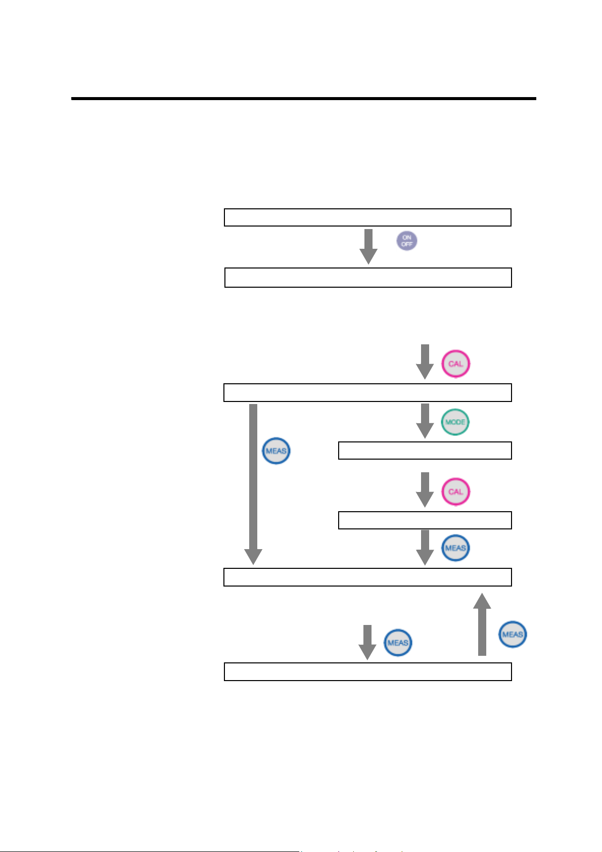
2.5 Conductivity measurement
The following shows the operational flow for conductivity
measurement
● Measuring conductivity: basic operational flow
1. Electrode preparation
2.
Conductivity Measurement mode (instantaneous value)
“ ● Setting the clock” page 31
“3.3.6 Conductivity unit setting” page 38
“3.3.7 Temperature coefficient setting” page 38
.
Power ON
2 Taking Measurements
3. Cell constant setting
4. Calibration mode
Preparation for standard solution
Auto Hold calibration
5.
Conductivity Measurement (instantaneous value)
“3.3.4 Auto data storage setting” page 35
“3.3.5 Sample ID# setting” page 37
6.
Auto Hold Measurement
About once
a year
Clear Hold
“3.1 Data memory function” page 27
ES-51 19
2 Taking Measurements
2.5 Conductivity measurement
● Electrode preparation
Refer to the electrode instruction manual and make sure
you have the correct electrode.
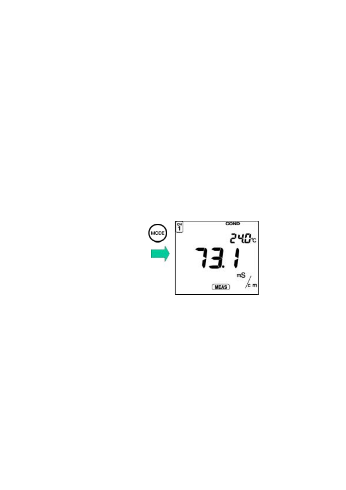
● Entering the Conductivity Measurement mode
1. Remove the electrode protective cap from the
electrode.
2. Immerse the electrode in pure (de-ionized)
water.
3. Select the Conductivity Measurement mode
when the pH Instantaneous Value Measurement
screen is displayed by pressing the MODE key.
The Conductivity Instantaneous Value
Measurement screen will appear.
20 HORIBA
2.5 Conductivity measurement
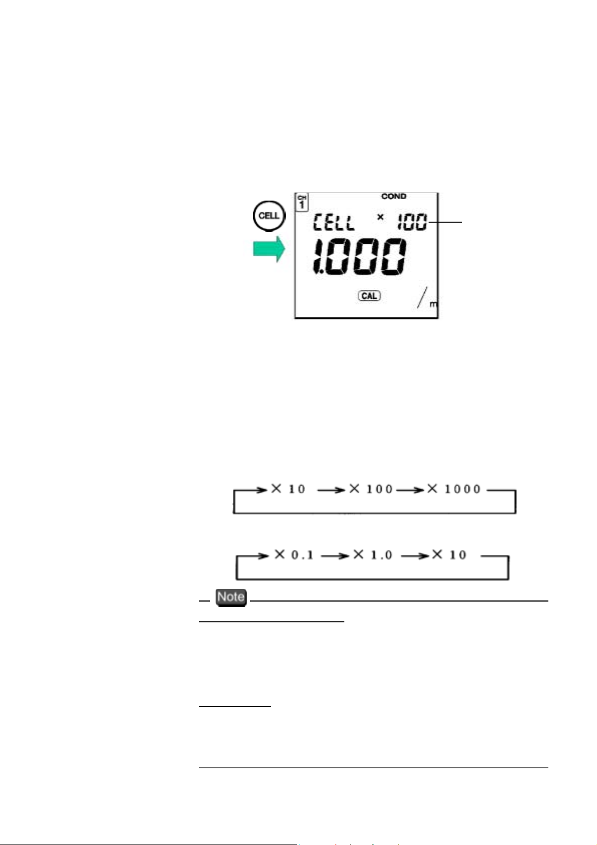
● CELL SET mode (Setting cell constant)
Set the cell constant the first time an electrode is
connected to the main unit of the meter.
1. To enter the CELL SET mode, press the CELL
key while in the Measurement mode.
2 Taking Measurements
Digit
2. Change the digit number using the ENTER key.
3. Press the ▲ and ▼ keys to set the cell constant
written on the electrode label.
Setting range: 0.700 – 1.300
To change the coefficient, use the following
procedure.
When the SI unit system (m-1) is set:
When the former unit system (cm-1) is set:
Temperature coefficient
The default value of the temperature coefficient is set a t
2.00%/ºC.
To change this setting, refer to “3.3.7 Temperature
coefficient setting” page 38.
Unit Setting
The default value of unit is S/m (SI unit system).
To change this setting to the former unit system S/cm,
refer to “3.3.6 Conductivity unit setting” page 38.
ES-51 21
 Loading...