

Horiba LAQUAtwin Salt-22 Operating Manual
Instruction Manual (Operation)
COMPACT WATER QUALITY METER
LAQUAtwin-Salt-22
Specifications
Model LAQUAtwin-Salt-22
Target Salinity
Measurement principle ISE method
Minimum sample volume More than 0.3 mL
Measurement range
Resolution
(default)
Calibration Up to 2 points
Accuracy
Waterproof IP67 (no failure when immersed in
Display Custom (monochrome) digital LCD
Operating
environment
Power CR2032 batteries (2)
Battery life Approx. 400 h continuous operation
Material ABS epoxy (main material)
Dimensions 164 29 20 mm (excluding projec-
Mass Approx. 50 g (excluding batteries)
0.01% to 25% by weight
Display range: Resolution
0.00% to 0.99%: 0.01%
1.0% to 9.9%: 0.1%
10% to 25%: 1%
Default: 0.5% and 5.0%
*2
±10% of reading value
water at a depth of 1 m for 30 min)
with backlight
Temperature: 5C to 40C
Humidity: 85% relative humidity or
less (no condensation)
(backlight off mode)
*4
tions)
*1 0.05 mL or more if sampling sheet B (sold sepa-
rately) is used.
*2 The closeness of agreemen t between a mea-
sured value and an actual value of standard solution after two-point calibration using 0.5% and
5.0% standard solutions.
The standard solution used for the later cali-
bration was measured after two-point calibration at 0.5% and 5.0%.
The calibration and measurement are per-
formed at the same temperature.
The error of standard solutions and rounding
error (1 digit) are not included.
*3 The meter cannot be used underwater.
*1
*4 When the backlight is used, battery life will
shorten.
Items in package
Items Quantity
Sensor S021 1
Meter 1
Storage case 1
Batteries CR2032 2
Standard solution 0.5% 1
5.0% 1
*3
Pipette 1
Sampling sheet B (5 sheet-pack) 1
Instruction manual (Operation) 1
Instruction manual (Before use) 1
Consumable parts sold separately
Items Specifications Part No.
Sensor
Standard
solution
Sampling
S021, Salt
3200459866
514-05, NaCl 0.5% 3999960112
514-50, NaCl 5.0% 3999960113
Y046, 100 sheet-pack 3200053858
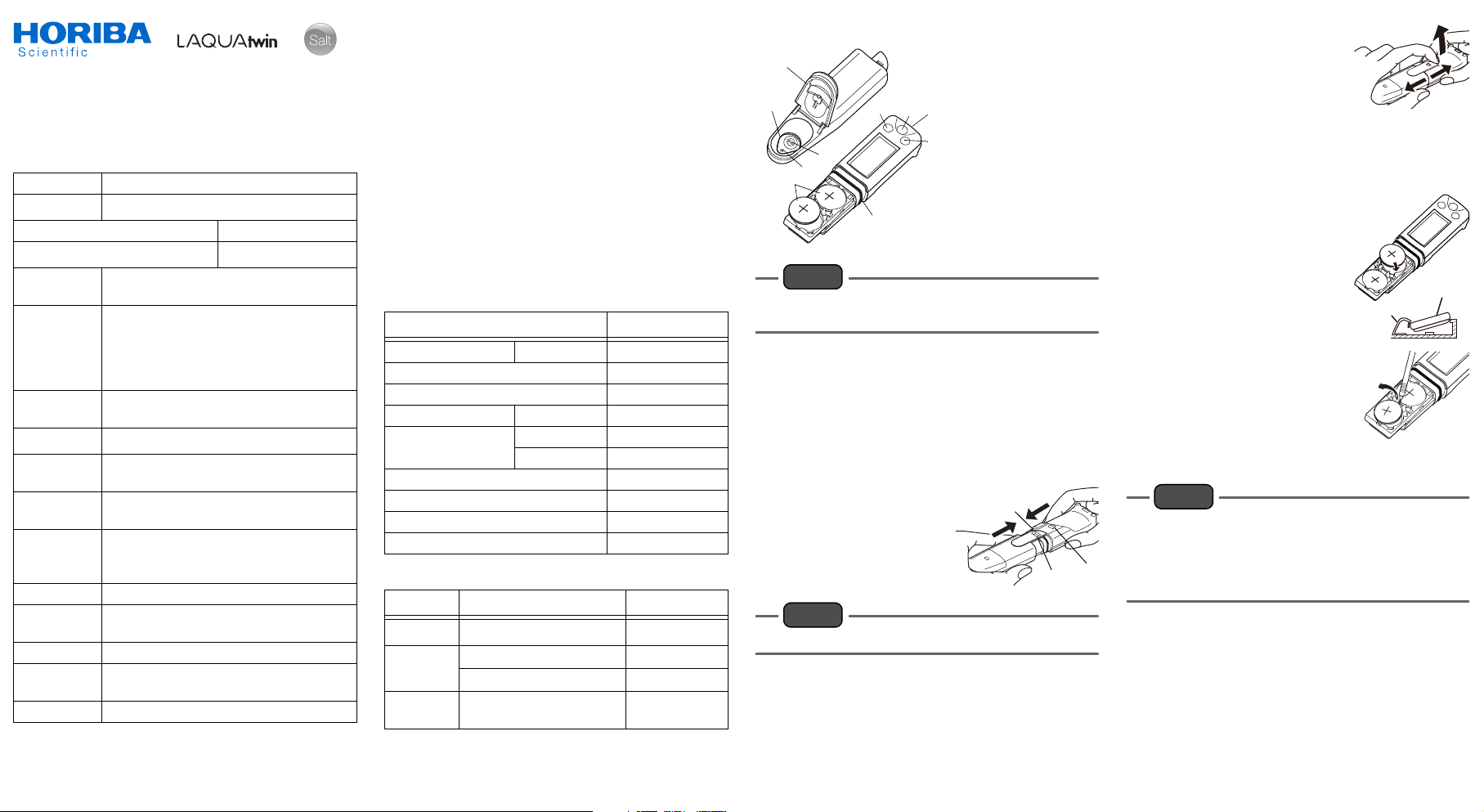
Part Names
2
1
4
3
5
6
9
Note
Press the switches 0.5 seconds or more u nless
otherwise specified.
1 Flat sensor
2 Light shield cover
3 Liquid junction
7
10
4 Response mem-
brane
8
5 Lithium batteries
6 MEAS switch
7 ON/OFF switch
8 CAL switch
9 Waterproof gasket
10 Strap eyelet
Initial Setup
Attaching/detaching the sensor
Attaching the sensor
1. Power OFF the meter.
2. Confirm that the waterproofing gasket is
clean and undamaged.
3. Slide the sensor
onto the meter so
that catch "A" on the
back of the meter fits
into hole "a" on the
sensor tongue as
shown.
Note
Be careful not to twist the waterproof gasket.
Waterproof
gasket
a
Detaching the sensor
1. Power OFF the meter.
2. Lift the sensor tongue
tip and slide the sensor
a little away from the
meter.
3. Pull out the sensor all the way from the
meter.
Inserting/removing batteries
Inserting the batteries
1. Power OFF the meter.
2. Slide both batteries into
the battery case as
shown.
Be sure to use two
CR2032 batteries, and put
them with the plus sides
Battery clip
(+) upwards.
Removing the batteries
1. Power OFF the meter.
2. Use a ball-point pen or
other tool to pry the batteries out from the clips as
shown.
Electrode conditioning
Note
Before using the sensor for the first time or
after several days of disuse, perform electrode
conditioning.
Perform calibration after electrode condition-
A
ing.
1. Place some drops of 5.0% standard solution to the flat sensor.
2. Wait a few hours before use.
There is no need to switch the meter ON.
3. Clean the flat sensor with running water.
Battery
sheet B
LAQUAtwin-Salt-22 Operation
CODE: GZ0000460290
March, 2017
1 2017 HORIBA Advanced Techno Co., Ltd.

Basic Operation
Power ON
1. Press and hold the ON/
OFF switch.
The power is switched ON,
and the meter model
number is displayed on the
LCD.
Power OFF
1. Press and hold the ON/OFF switch.
The power is switched OFF.
Calibration
Calibration is required before measurement.
Use standard solution within the measurement
range in the specifications.
Tip
Calibration values are saved even if the meter
is switched OFF.
Calibration value is rewritten if calibration is
repeated using the same standard solution.
Calibration points
The number of calibration points is up to 2.
Multi-point calibration
1. Set the salinity of standard solution for calibration referring to " 1st calibration
point setting" (page 5) and " 2nd calibration point setting" (page 5).
The 1st point is set to 0.5% and the 2nd point
is set to 5.0% by the default.
2. Open the light shield cover and place some
drops of the standard solution on the flat
sensor taking care to cover the entire flat
sensor.
Rinsing the sensor with the standard solution
beforehand will provide a more accurate
calibration as it will reduce sample crossover
contamination.
3. Close the light shield cover and press the
CAL switch.
The meter enters the CAL mode and blinks the
display of the set 1st-point salinity. Pressing
the MEAS switch switches the displayed value
between the set salinity.
Light shield cover
4. With the set salinity of the 1st point displayed, press the CAL switch.
and blink, and the calibration value is
displayed.
After the calibration is complete, and
stop blinking and the measured value is
displayed.
The calibration value at 25C is displayed for 1
s and the display returns to the measurement
mode automatically.
5. Open the light shield cover and remove the
standard solution. Then remove moisture
on the sensor by gently dabbing with a so ft
tissue.
This completes the 1st point calibration.
6. To perform 2nd point calibration, repeat
steps 2. to 5.
Calibratio n error
If blinks and Er4 (error display) appears, the calibration
has failed.
Perform electrode conditioning.
Check that the correct standard solution is used,
and repeat calibration after cleaning the sensor.
If the calibration repeatedly fails when using the
correct standard solution(s), the sensor may
have deteriorated. Replace the sensor with new
one.
Tip
For accurate measurement, calibrate using 2
points of st anda rd solution with a t enfold or mo re
salinity difference encompassing the target salinity.
When the salinity to be measured is very high or
very low, accuracy may be poorer.
Measurement
Sample setting
1. Open the light shield cover and put some
drops of sample on the flat sensor to cover
the entire flat sensor.
2. Close the light shield cover.
Measurement mode
The auto stable (AS) mode and the auto hold
(AH) mode can be selected. Refer to " Measurement mode change" (page 5) for the operation to set the measurement mode.
Auto stable (AS) mode
This is the default setting. appears when
the measured value meets the stability criteria.
If the value changes, disappears.
1. Confirm that the meter is in the measurement mode, and place a sample on the sensor.
When the read value meets
the stability criteria,
appears and the reading is
locked.
2. Document the displayed value when
appears.
If the read value does not meet the stability
criteria, disappears and the reading
changes with time.
Auto hold (AH) mode
appears when the measured value meets
the stability criteria. The reading then locks
and will not change until the MEAS switch is
pressed for the next measurement.
1. Confirm that the meter is in the measurement mode, and place a sample on the sensor.
2. Press the MEAS switch.
The auto hold function is
activated.
blinks until the
measured value has
stabilized.
When the measured value is stable, stops
blinking and the displayed value is locked with
and displayed simultaneously.
3. Document the displayed value.
4. Press the MEAS switch.
The auto hold function is deactivated and
disappears.
Be sure to perform this step before starting the
next measurement. Or, you may mistake the
displayed hold value for the next measured
value.
LAQUAtwin-Salt-22 Operation 2 CODE: GZ0000460290
 Loading...