

Horiba LAQUA F-72 Operating Manual

Instruction Manual
表紙は別途デザインの表紙とする
pH/ION METER
F-72

■ Preface
This manual describes the operation of the F-72 pH/ION Meter.
Be sure to read this manual before using the product to ensure proper and safe
operation of the instrument. Also safely store the manual so it is readily possible
whenever necessary.
Product specifications and appearance, as well as the contents of this manual
are subject to change without notice.
■ Warranty and Responsibility
HORIBA, Ltd. warrants that the Product shall be free from defects in material
and workmanship and agrees to repair or replace free of charge, at option of
HORIBA, Ltd., any malfunctioned or damaged Product attributable to
responsibility of HORIBA, Ltd. for a period of one (1) year from the delivery
unless otherwise agreed with a written agreement. In any one of the following
cases, none of the warranties set forth herein shall be extended;
• Any malfunction or damage attributable to improper operation
• Any malfunction attributable to repair or modification by any person not
authorized by HORIBA, Ltd.
• Any malfunction or damage attributable to the use in an environment not
specified in this manual
• Any malfunction or damage attributable to violation of the instructions in
this manual or operations in the manner not specified in this manual
• Any malfunction or damage attributable to any cause or causes beyond
the reasonable control of HORIBA, Ltd. such as natural disasters
• Any deterioration in appearance attributable to corrosion, rust, and so on
• Replacement of consumables
HORIBA, LTD. SHALL NOT BE LIABLE FOR ANY DAMAGES RESULTING
FROM ANY MALFUNCTIONS OF THE PRODUCT, ANY ERASURE OF DATA,
OR ANY OTHER USES OF THE PRODUCT.
■ Trademarks
Generally, company names and brand names are either registered trademarks
or trademarks of the respective companies.
■ Unauthorized Reprinting or Copying of This
Operation Manual
No unauthorized reprinting or copying of all or part of this operation manual is
allowed. The utmost care has been used in the preparation of this operation
manual.
Copyright © 2011 by HORIBA, Ltd. All rights reserved.
REGULATIONS
■ Conformable Directive
This equipment conforms to the following directives and standards:
Directives: The EMC Directive 2004/108/EC
The Low Voltage Directive 2006/95/EC
Standards: [the EMC Directive] EN61326-1:2006
Class B, Basic requirements
[the Low Voltage Directive] EN61010-1:2010(Ed.3.0)
● Installation Environment
This product is designed for the following environment.
- Overvoltage category II
- Measurement category I
WARNING: Do not use the equipment for measurements within
measurement categories II, III and IV.
● Information on Disposal of Electrical and Electronic Equipment and
Disposal of Batteries and Accumulators
The crossed out wheeled bin symbol with underbar shown on the
product or accompanying documents indicates the product requires
appropriate treatment, collection and recycle for waste electrical and
electronic equipment (WEEE) under the Directive 2002/96/EC, and/or
waste batteries and accumulators under the Directive 2006/66/EC in
the European Union.
The symbol might be put with one of the chemical symbols below. In
this case, it satisfies the requirements of the Directive 2006/66/EC for
the object chemical.
This product should not be disposed of as unsorted household waste.
Your correct disposal of WEEE, waste batteries and accumulators will
contribute to reducing wasteful consumption of natural resources, and
protecting human health and the environment from potential negative
effects caused by hazardous substance in products.
Contact your supplier for information on applicable disposal methods.
REGULATIONS
I

■ FCC Rules
Any changes or modifications not expressly approved by the party
responsible for compliance shall void the user's authority to operate the
equipment.
● WARNING
This equipment has been tested and found to comply with the limits for
a Class A digital device, pursuant to part 15 of the FCC Rules. These
limits are designed to provide reasonable protection against harmful
interference when the equipment is operated in a commercial
environment. This equipment generates, uses, and can radiate radio
frequency energy and, if not installed and used in accordance with the
instruction manual, may cause harmful interference to radio
communications.
Operation of this equipment in a residential area is likely to cause
harmful interference in which case the user will be required to correct
the interference at his own expense.
REGULATIONS
II
SAFETY OPERATION
■ Hazard Classification and Warning Symbols
Warning messages are described in the following manner. Read the
messages and follow the instructions carefully.
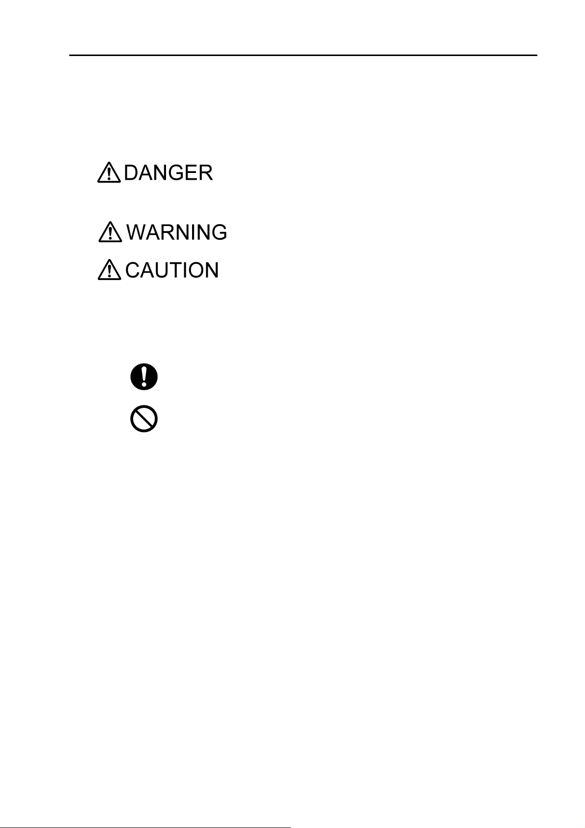
● Hazard classification
This indicates an imminently hazardous situation which,
if not avoided, will result in death or serious injury. This
signal word is to be limited to the most extreme
situations.
This indicates a potentially hazardous situation which, if
not avoided, could result in death or serious injury.
This indicates a potentially hazardous situation which, if
not avoided, may result in minor or moderate injury. It
may also be used to alert against unsafe practices.
Without safety alert indication of hazardous situation
which, if not avoided, could result in property damage.
● Warning symbols
Description of what should be done, or what should be followed
Description of what should never be done, or what is prohibited
SAFETY OPERATION
III

SAFETY OPERATION
■ Safety Precautions
This section provides precautions to enable you to use the product
safely and correctly and to prevent injury and damage. The terms of
DANGER, WARNING, and CAUTION indicate the degree of imminency
and hazardous situation. Read the precautions carefully as it contains
important safety messages.
Do not use an unspecified AC adapter.
Otherwise, it may heat up or be ignited resulting in a fire or an accident.
Do not disassemble or modify the meter.
Otherwise, it may heat up or be ignited resulting in a fire or an accident.
WARNING
CAUTION
Harmful chemicals
Some ion electrodes are used with hazardous standard solutions. Handle them
with care.
If the internal solution comes in contact with the skin, wash it off immediately. If it
gets into eyes, flush with plenty of water and then consult a doctor.
Harmful chemicals
The internal solution of an electrodes is highly concentrated potassium chloride
(3.33 mol/L KCl).
If the internal solution comes in contact with the skin, wash it off immediately. If it
gets into eyes, flush with plenty of water and then consult a doctor.
Broken glass
Broken glass may cause injury.
The outer tube and tip of an electrode are made of glass.
Handle them with care.
Do not use the cable of serial communication, USB, or AC adapter under wet or
humid conditions.
Otherwise, it may cause an fire, electric shock, or breakage.
IV

SAFETY OPERATION
■ Product Handling Information
● Operational Precautions
●
Do not drop, crash, or give any physical impact on the instrument.
●
Do not immerse the instrument into alcohol, organic solvent, strong
acid, strong alkaline, or the like. The instrument body contains ABS
resin, acrylic resin, and some rubber parts.
●
If the instrument is dropped into water or gets wet, wipe it using soft
cloth. Do not heat to dry it with a hair-dryer (or the like).
●
Use fingers to press the operation keys or the touch panel.
Do not use a hard object like a metal stick or rod.
●
Be careful not to let water into the instruction inside.
The instrument is not water-proof.
●
To disconnect an electrode or interface cable, hold the connector and
pull it off. If you pull at the cable, it may cause a breakage.
●
The touch panel is capacitance-type. Make sure to turn OFF the
power before cleaning the panel. If you wipe it with the power ON, it
may cause instrument malfunction.
●
RS-232C or USB communication between the instrument and a personal computer may fail because of environmental conditions, such
as (radio/electromagnetic) noise.
● Environmental conditions for use and storage
●
Temperature: 0°C to 45°C
●
Humidity: under 80% in relative humidity and free from
condensation
Avoid the following conditions:
●
Dusty environment
●
Strong vibration
●
Direct sunlight
●
Corrosive gas environment
●
Close to an air-conditioner
●
Direct wind
● Transportation
When transporting the instrument, repackage it in the original package
box. Otherwise, it may cause instrument breakage.
● Disposal
Standard solution used for the calibration must be under neutralized
before the disposal. As for the disposal of the meter, treat it as an
industrial waste.
V

MANUAL INFORMATION
■ Description in This Manual
This interprets the necessary points for correct operation and notifies
the important points for handling the instrument.
This indicates the part of where to refer the information.
HINT!
This indicates reference information.
MANUAL INFORMATION
VI

Contents
Chapter 1 OVERVIEW ................................................................................ 1
1.1 Description of Each Part ........................................................................ 1
1.1.1 Rear ................................................................................................ 1
1.1.2 Display ............................................................................................ 1
1.1.3 Left Side .......................................................................................... 2
1.1.4 Right Side ....................................................................................... 2
1.1.5 Accessories .................................................................................... 2
1.1.6 Operation Keys ............................................................................... 3
1.1.7 Icons (Icon Bar) .............................................................................. 4
1.1.8 Status Icons .................................................................................... 5
1.1.9 Meas Screen ................................................................................... 6
1.2 Basic Operation of Touch-Panel and Touch-Key ................................ 7
1.3 Function and Operation of the Meas Screen ....................................... 8
1.4 Function and Operation of the CAL Screen ....................................... 10
1.5 Assembling the Electrode Stand ........................................................ 11
1.6 Connecting the Electrode .................................................................... 12
1.6.1 Electrode Connector ..................................................................... 12
1.6.2 Temperature Connector ................................................................ 12
1.7 Connecting the Power Source ............................................................ 13
1.8 Connecting the Printer ......................................................................... 13
1.9 Connecting the Personal Computer ................................................... 14
1.10 Turn ON the Power ............................................................................. 15
Chapter 2 Before Measurement (Meter SET) ......................................... 16
2.1 Meter SET Screen ................................................................................. 16
2.2 Auto Hold Setting ................................................................................. 16
2.3 Custom Setting ..................................................................................... 17
2.4 Sample Name Setting ........................................................................... 18
2.5 Interval Memory Setting ....................................................................... 19
2.6 USB Memory Setting ............................................................................ 20
2.7 Printer Setting ....................................................................................... 22
2.8 Screen Settings .................................................................................... 24
2.9 Sound Setting ....................................................................................... 26
2.10 Language Setting ............................................................................... 27
2.11 Security Setting .................................................................................. 27
2.12 User Entry/Info Change/Delete .......................................................... 29
2.13 Date Setting ......................................................................................... 31
2.14 Analog Output Adjustment ................................................................ 32
2.15 Temperature Sensor Calibration ....................................................... 33
2.16 Resetting to Factory Defaults ............................................................ 34
Chapter 3 pH Measurement .................................................................... 35
3.1 pH Calibration Setting .......................................................................... 35
3.1.1 Standard Solution ......................................................................... 35
3.1.2 Calibration Points .......................................................................... 35
VII

Contents
3.1.3 Calibration Interval ........................................................................ 36
3.1.4 Checking Before Use .................................................................... 37
3.2 pH Calibration ....................................................................................... 38
3.2.1 Calibration Preparation ................................................................. 38
3.3 Checking Before Use ............................................................................ 41
3.4 Calibration for Custom selection ........................................................ 42
3.4.1 Calibration Preparation ................................................................. 42
3.5 pH Measurement Setting ...................................................................... 43
3.6 Indicated Resolution of pH Measurement Values Setting ................ 43
3.7 Temperature Compensation Setting ................................................... 44
3.7.1 Solution Temperature Entry
in MTC (Manual Temperature Compensation) .............................. 44
3.8 Temperature Conversion Function Setting ........................................ 45
3.8.1 Temperature Coefficient Setting ................................................... 45
3.9 Alarm Setting ........................................................................................ 46
3.9.1 Input Alarm, Upper Limit or Lower Limit ........................................ 46
3.10 Electrode Model Setting ..................................................................... 47
3.10.1 Electrode Model Selection .......................................................... 47
3.10.2 Electrode Model Entry ................................................................. 47
3.11 Electrode Lot No. Setting ................................................................... 48
3.12 pH Measurement ................................................................................. 49
Chapter 4 ION Measurement .................................................................. 50
4.1 ION Calibration Setting ........................................................................ 50
4.1.1 Calibration Points Setting .............................................................. 50
4.1.2 Checking Before Use .................................................................... 51
4.2 ION Calibration ..................................................................................... 52
4.2.1 Calibration Preparation ................................................................. 52
4.3 Checking Before Use ............................................................................ 54
4.4 ION Measurement Setting .................................................................... 55
4.5 ION Measurement Unit Setting ............................................................ 55
4.6 Temperature Compensation Setting ................................................... 56
4.6.1 Solution Temperature Entry
in MTC (Manual Temperature Compensation) .............................. 56
4.7 Alarm Setting ........................................................................................ 57
4.7.1 Input Upper or Lower Limit Values ................................................ 57
4.8 Electrode Model Setting ....................................................................... 59
4.8.1 Electrode Model Selection ............................................................ 59
4.8.2 Electrode Model Entry ................................................................... 59
4.8.3 ION Valency Setting
(For Customized electrode model only) ........................................ 60
4.9 Electrode Lot No. Setting ..................................................................... 60
4.10 ION Measurement ............................................................................... 61
Chapter 5 mV Measurement ................................................................... 62
VIII

Contents
5.1 mV Measurement Setting ..................................................................... 62
5.2 Temperature Setting ............................................................................. 62
5.2.1 Solution Temperature Entry
in MTC (Manual Temperature Setting) ......................................... 63
5.3 Alarm Setting ........................................................................................ 63
5.3.1 Input Upper or Lower Limit Values ............................................... 64
5.4 Electrode Model Setting ....................................................................... 65
5.4.1 Electrode Model Selection ............................................................ 65
5.4.2 Electrode Model Entry .................................................................. 65
5.5 Electrode Lot No. Setting ..................................................................... 66
5.6 mV Measurement .................................................................................. 67
Chapter 6 ORP Measurement ................................................................. 68
6.1 ORP Calibration .................................................................................... 68
6.2 ORP Measurement Setting .................................................................. 69
6.3 Temperature Setting ............................................................................. 69
6.3.1 Solution Temperature Entry
in MTC (Manual Temperature Setting) ......................................... 69
6.4 Alarm Setting ........................................................................................ 70
6.4.1 Input Upper or Lower Limit Values ............................................... 70
6.5 Electrode Model Setting ....................................................................... 71
6.5.1 Electrode Model Selection ............................................................ 71
6.5.2 Electrode Model Entry .................................................................. 71
6.6 Electrode Lot No. Setting ..................................................................... 72
6.7 ORP Measurement ................................................................................ 73
Chapter 7 Application Mode ................................................................... 74
7.1 Standard Addition Method Mode ........................................................ 74
7.1.1 Measurement Using Standard Addition Method ........................... 74
7.1.2 Known Addition Method and Sample Addition Method ................. 74
7.1.3 General Cautions for Standard Addition Method .......................... 75
7.1.4 Standard Addition Method MEAS screen ..................................... 75
7.1.5 Known Addition Method (Single) Measurement ........................... 76
7.1.6 Known Addition Method (Double) Measurement .......................... 77
7.1.7 Sample Addition Method (Single) Measurement .......................... 78
7.1.8 Sample Addition Method (Double) Measurement ......................... 79
Chapter 8 Periodic Inspection Mode ...................................................... 81
8.1 pH Periodic Inspection Mode Setting ................................................. 81
8.1.1 Settings ......................................................................................... 81
8.1.2 JIS Mode ....................................................................................... 82
8.1.3 Pharmacopoeia Mode ................................................................... 84
8.1.4 Simulator (X-51) Mode .................................................................. 85
8.2 ION Periodic Inspection Mode Setting ............................................... 87
8.3 Comment Input ..................................................................................... 88
IX

Contents
Chapter 9 Data ......................................................................................... 89
9.1 Measurement data_All .......................................................................... 89
9.2 Deleting Saved Data ............................................................................. 89
9.3 Measurement data_latest50 ................................................................. 90
9.4 Measured data_Search ......................................................................... 90
9.5 Cal. results_All ...................................................................................... 91
9.6 Copy all Meas. Data ............................................................................. 91
9.7 Delete all meas. Data ............................................................................ 92
9.8 Delete all cal. data ................................................................................. 92
Chapter 10 Specifications ....................................................................... 93
10.1 Specifications ..................................................................................... 93
10.2 Default Settings .................................................................................. 94
10.2.1 Meter Default Settings ................................................................ 94
10.2.2 Measurement Condition Default Settings
(Can be set per operator) .............................................................. 95
10.3 Options ................................................................................................ 99
X
Chapter 1 OVERVIEW
This chapter describes functions and basic operations of the instrument.
1.1 Description of Each Part
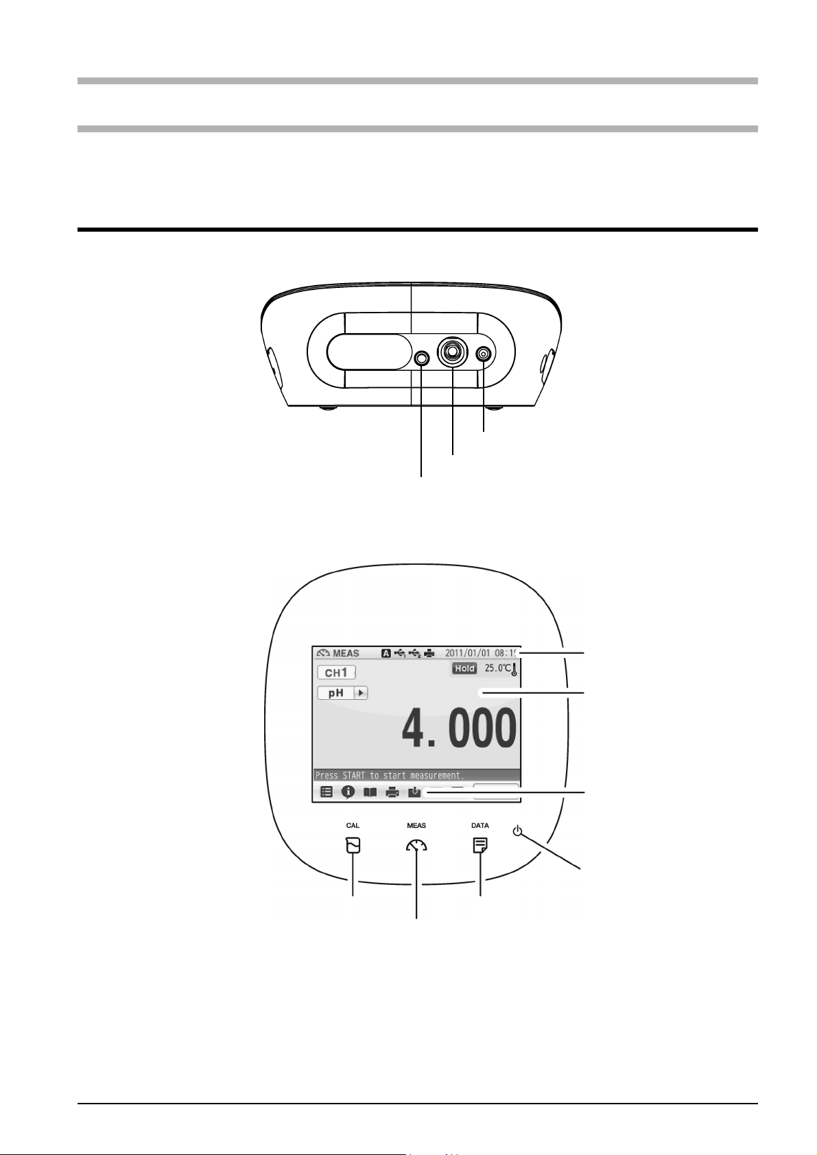
1.1.1 Rear
CH1 reference electrode
Chapter 1 OVERVIEW
1.1.2 Display
CH1 measurement electrode
CH1 for temperature electrode
Status bar
Touch panel
Icon bar
POWER key
CAL key
MEAS key
DATA key
F-72 1
Chapter 1 OVERVIEW
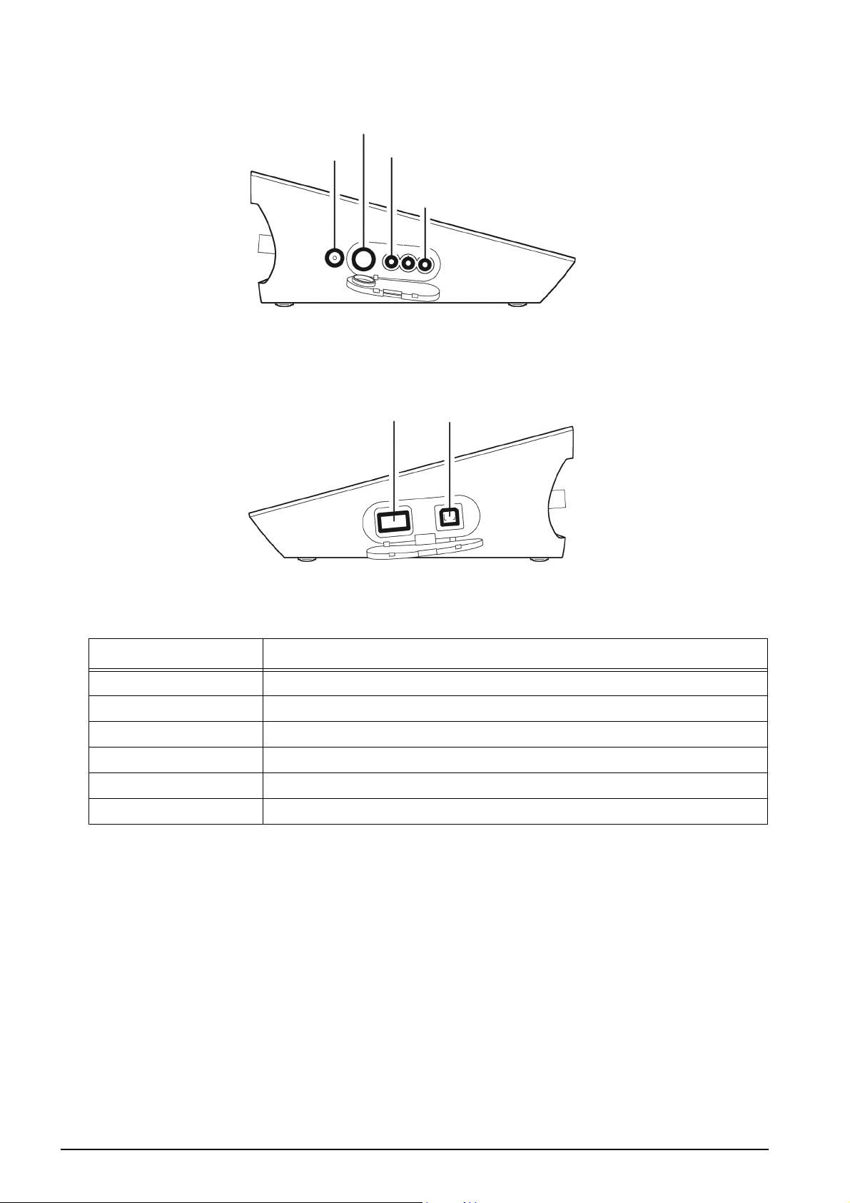
1.1.3 Left Side
Serial communication connector (RS-232C)
AC adapter connector
1.1.4 Right Side
Analog output connector 1 (CH1 data)
Connector for
USB memory
Analog output connector 3 (Alarm)
Connector for
with a personal computer
USB communication
1.1.5 Accessories
Name Function
AC adapter Used to power the instrument.
Electrode stand Used to move and set electrodes during measurement.
Rubber cover Protects the instrument side surfaces.
Instruction manual Instructs the usage of the instrument.
Quick manual Instructs the operations of calibration and measurement.
Ferrite core Attach this device to the AC adapter cable to reduce interference.
*Clock battery (CR-2032) is put into the battery cover at the instrument bottom.
2HORIBA
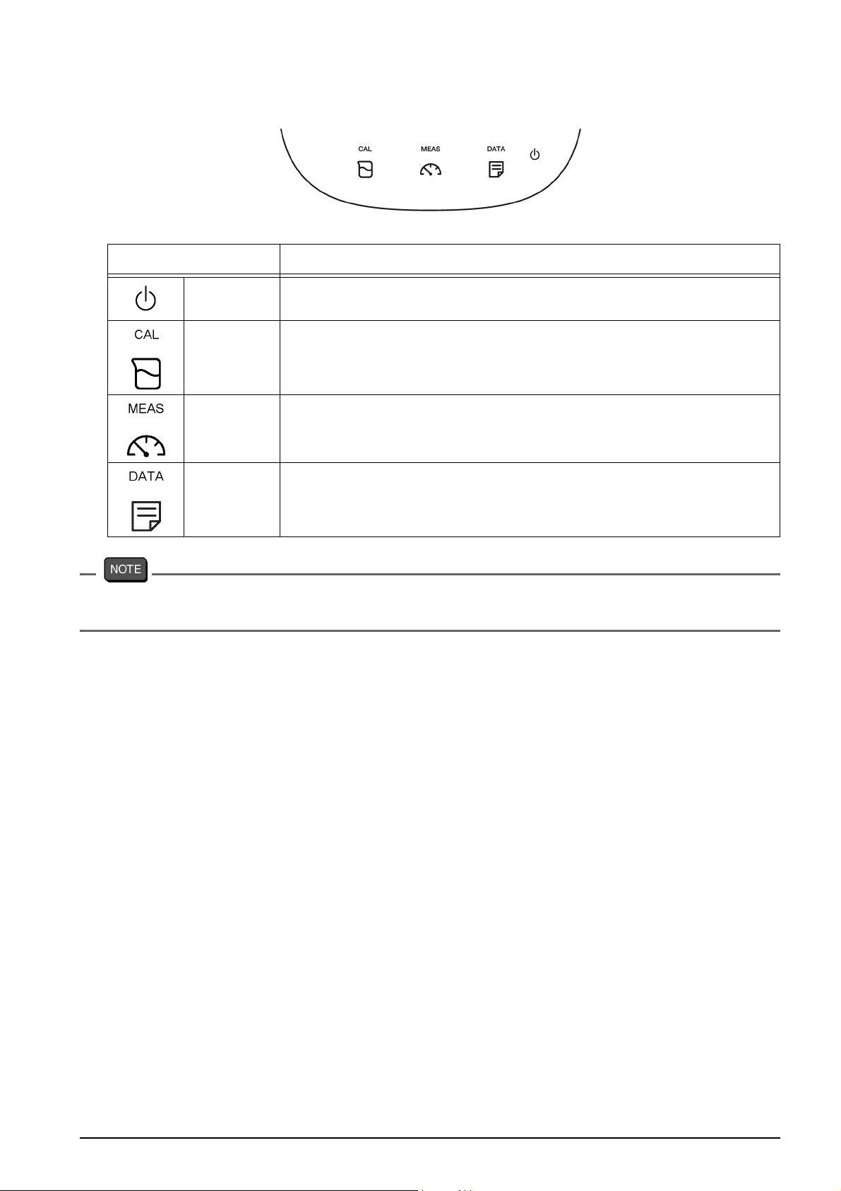
1.1.6 Operation Keys
Operation key Function
Chapter 1 OVERVIEW
POWER
CAL Displays the calibration screen (CAL screen).
MEAS Displays the measurement screen (MEAS screen).
DATA Displays the data screen (DATA screen).
The POWER key does not work for 10 seconds after the AC adapter is connected.
Wait for a while after connecting AC adapter.
Turns ON or OFF the power.
(Press and hold for 2 seconds or more.)
F-72 3
Chapter 1 OVERVIEW
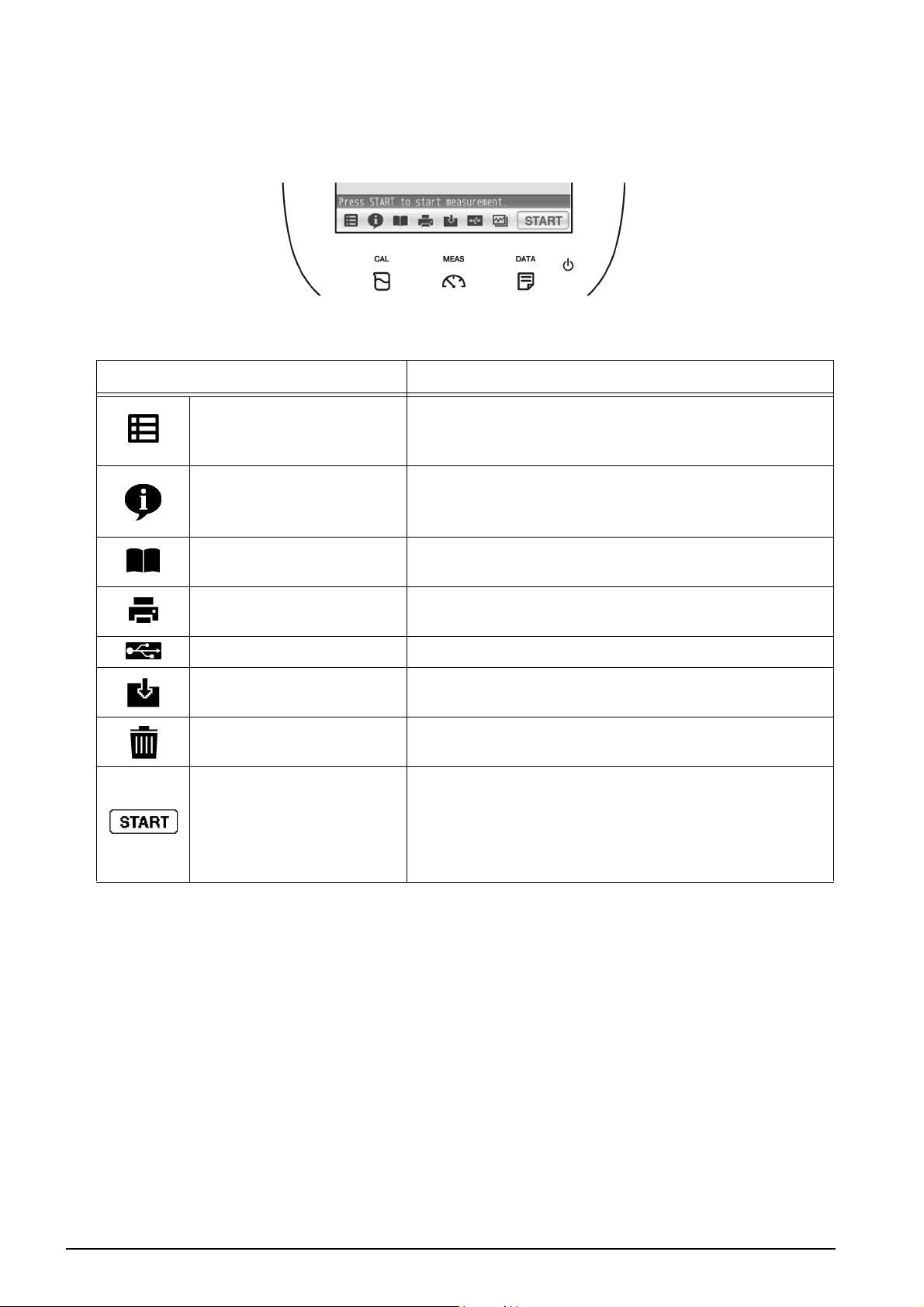
1.1.7 Icons (Icon Bar)
The icons displayed on the bottom of the touch panel allow you to set up the instrument,
check calibration information, and print out and save data.
Icon Function
Used to perform measurement, display the Meter
Menu
Information
SET screen, and switch to the inspection and
application modes.
Used to check calibration information on the MEAS
or CAL screen, and application information on the
Meter SET screen.
User's guide
Printer
Save in USB Used to save measured data into a USB memory.
Save data
Trash box
Operation
Used to check operation instructions and
information about measurement and maintenance.
Used to print out measurement or calibration
values or saved data when a printer is connected.
Used to save measurement values displayed on
the screen into the instrument.
Used to delete calibration data or the data saved in
the instrument.
Used to start and stop the operations of
measurement and calibration, and to change to the
instantaneous value display.
The icon label depends on the corresponding
operation.
4HORIBA
Chapter 1 OVERVIEW
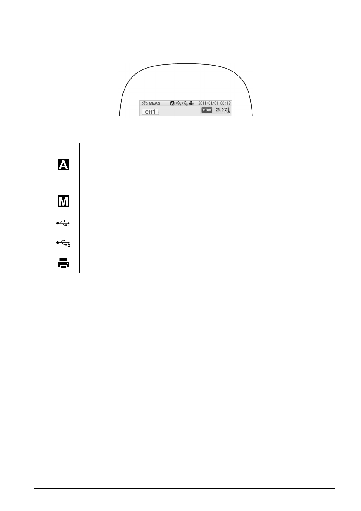
1.1.8 Status Icons
The icons displayed on the top of the touch panel show information on the instrument.
Status icon Function
Shows that the automatic hold function is ON, and that the
end point is determined automatically according to input
Auto hold
Manual hold
signals from the electrode based on the pre-selected stability
criterion of measurement values.
Refer to "2.2 Auto Hold Setting" (P.16).
Shows that the manual hold function is ON, and that the end
point is determined manually.
Refer to "2.2 Auto Hold Setting" (P.16).
USB1
USB2
Printer
*1: These icons appear when a USB cable is connected, but it does not always mean that
the communication is conducted.
*1
*1
Shows that the instrument is connected with a personal
computer via a USB cable.
Shows that the instrument is connected with a USB data
storage media.
Shows that the instrument is connected with a printer with a
dedicated printer cable.
F-72 5
Chapter 1 OVERVIEW
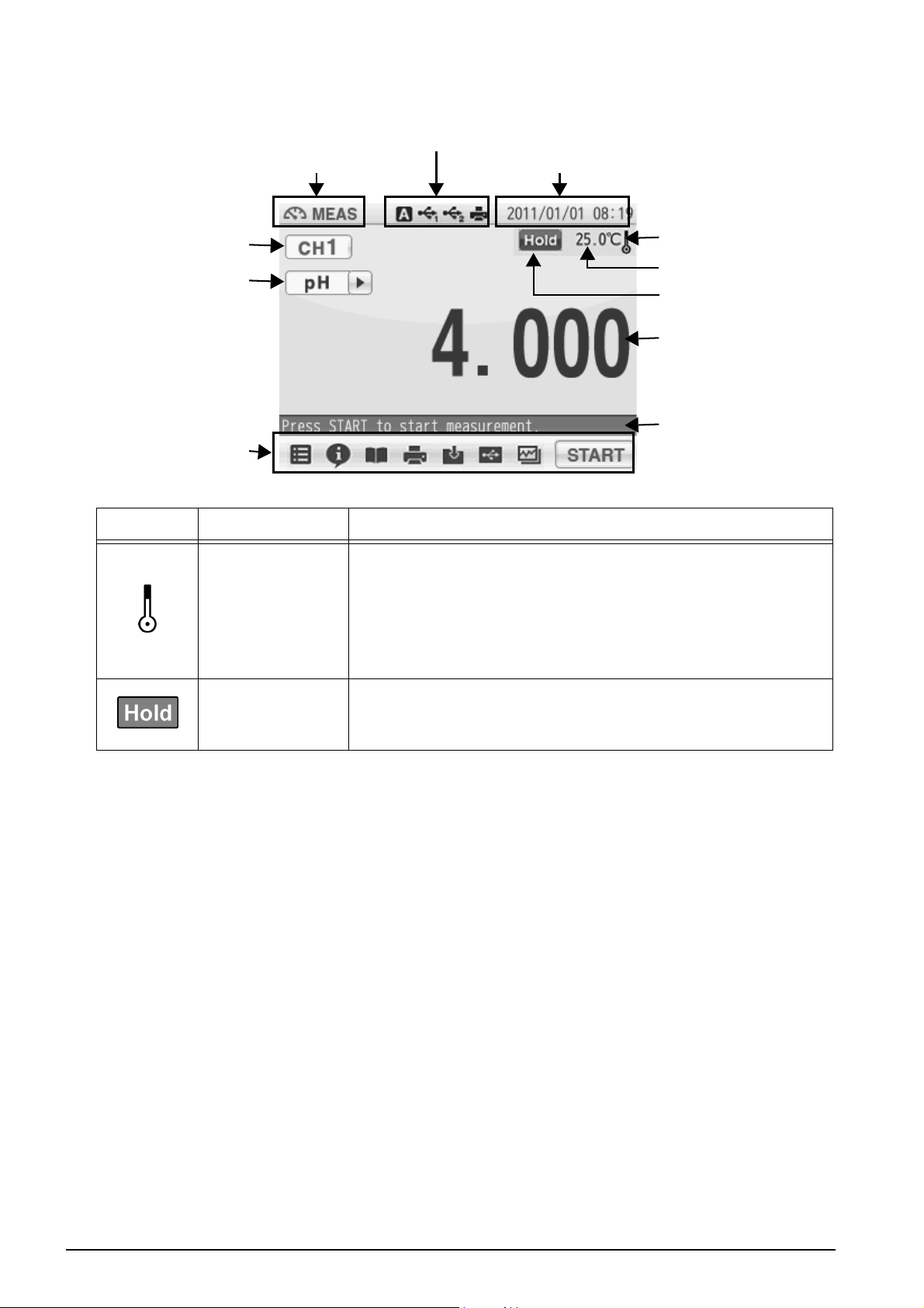
1.1.9 Meas Screen
Status
Measurement mode
Channel
Measurement item
Icon
Indicator Name Description
Temperature
compensation
electrode
connection
indicator
Displayed: A temperature compensation electrode
Not displayed: The displayed temperature is preset
Date and time
is connected.
The displayed temperature is the
electrode temperature (ATC).
value (MTC).
Temperature
compensation
electrode
connection
indicator
Temperature
HOLD indicator
Measurement values
Measurement
operation
information
HOLD indicator
Not displayed: An instantaneous value is displayed.
Blinking: In-process for HOLD
Lighting up: HOLD completed.
6HORIBA
Chapter 1 OVERVIEW
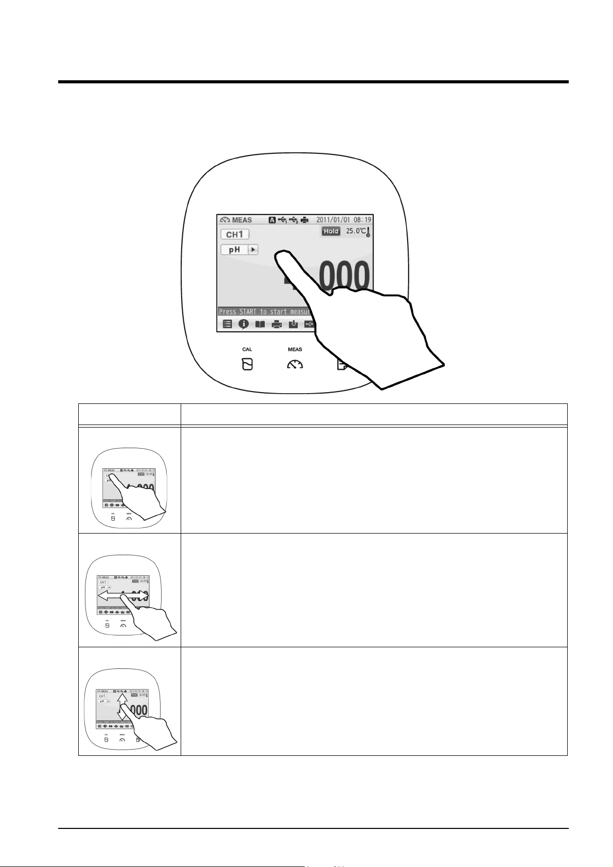
1.2 Basic Operation of Touch-Panel and Touch-Key
The instrument has touch panel and keys and you can operate it by touching the screen.
The 3 basic operations of Tap, Flick, and Drag allow you to operate the instrument
intuitively. This section describes the basic operations.
Operation Description
Tap Tap on the screen lightly once with a finger.
Tap a menu item or icon to select it or change settings.
Flick Touch and flick on the screen with a finger.
Used to switch to the digital or graph display on the MEAS or CAL
screen.
Drag Keep a finger in contact with the screen and drag it on the screen.
Used to search a setting item, or measurement data on the DATA
screen. When a scroll bar is displayed on the right of the screen, you
can scroll the screen by this operation.
F-72 7
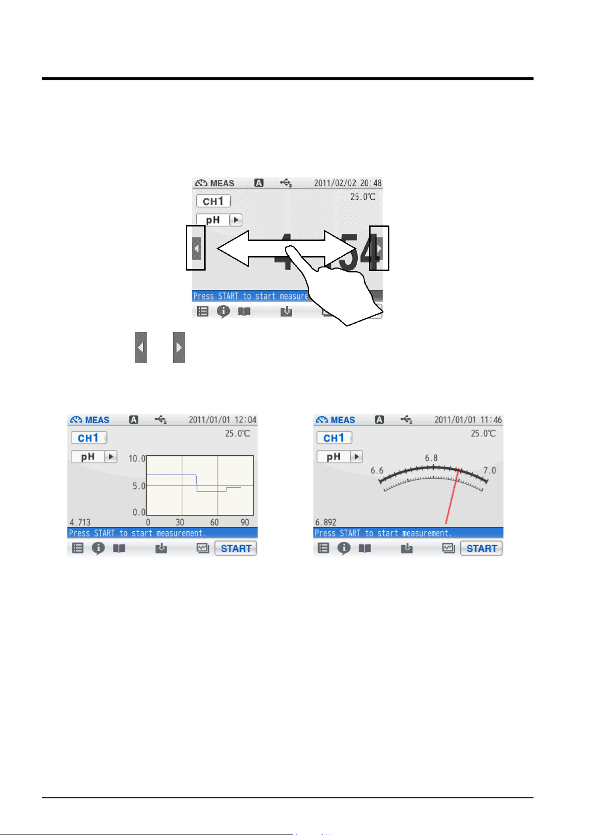
Chapter 1 OVERVIEW
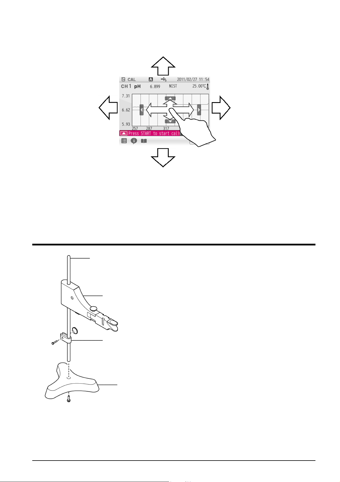
1.3 Function and Operation of the Meas Screen
The MEAS screen has three display methods to check variation and tendency of
measurement values.
You can shift the screen to the digital, graph or analog screen by flicking it.
Digital display
If arrows, like and , appear when you touch the screen, you can flick in the directions
to switch the screen display.
Graph display Analog display
8HORIBA
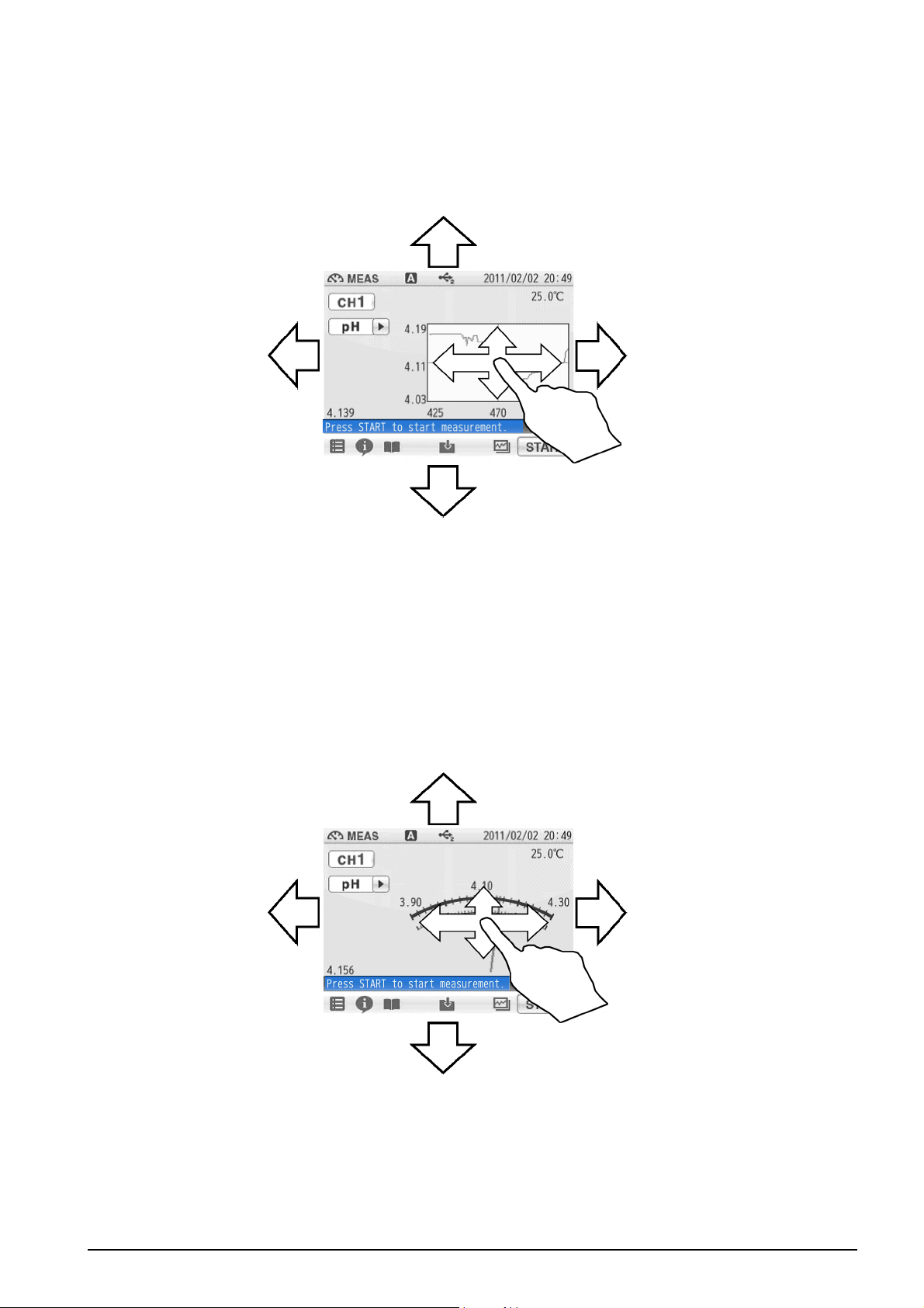
● Graph display
You can change the scale of the vertical axis in the graph display.
It allows you to check a small change in measurement values.
The vertical axis is zoomed in.
The displayed range narrows.
Chapter 1 OVERVIEW
Displays the next or
the latest data.
The vertical axis is zoomed in.
The displayed range narrows.
Tap on the screen after the above operations, and the latest data will be displayed in
optimized range.
● Analog display
You can change the scale of the vertical axis in the analog display.
It allows you to check a small change in measurement values.
The displayed range narrows. It allows you to check the
detailed variation of measurement values.
Displays the
previous data.
Lowers the range.
The displayed range broadens. It allows you to check the
wide-ranging variation of measurement values.
Tap on the screen after the above operations, and the latest data will be displayed in
optimized range.
Raises the range.
F-72 9
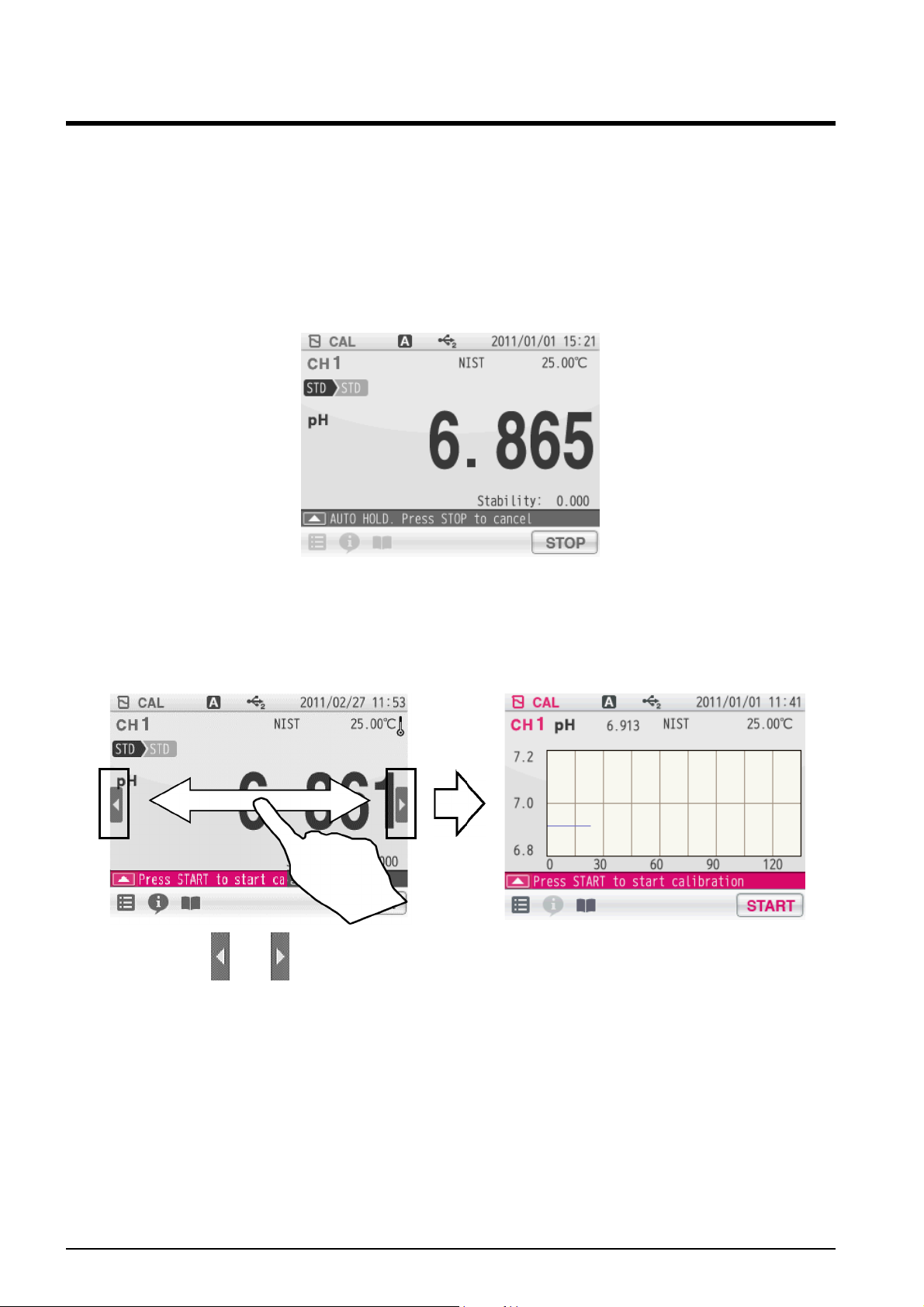
Chapter 1 OVERVIEW
1.4 Function and Operation of the CAL Screen
The CAL screen has 2 functions and allows you to check the stability of readings.
● Stability: Only pH and ION calibration
You can check the change in the indicated value by seeing the stability always displayed
under the indicated value in the digital display. The stability value is a deviation between
the maximum and minimum values in the last 10 seconds.
For example, you will make a good pH calibration during the stability value is 0.002 or less,
though it depends on measurement environment.
● Graph display
Flick the screen during calibration to shift to the graph display.
Digital display Graph display
If arrows, like and , appear when you touch the screen, you can flick in the directions
to switch the screen display.
You can change the width of graph so that you can easily recognize variation of the
indicated value at the graph screen.
10 HORIBA
The width of measurement range becomes narrower
to enlarge the display of measurement values.
Chapter 1 OVERVIEW
Displays the next or
the latest data.
The width of measurement range becomes wider
to reduce the display of measurement values.
By tapping the graph screen after you have changed it, the graph screen range optimizes
automatically and displays the latest data.
Displays the
previous data.
1.5 Assembling the Electrode Stand
Stand shaft
1. Attach the stand shaft to the stand base.
Stand arm
Stopper
Stand base
2. Attach the stopper and the stand arm to
the stand shaft.
F-72 11
Chapter 1 OVERVIEW
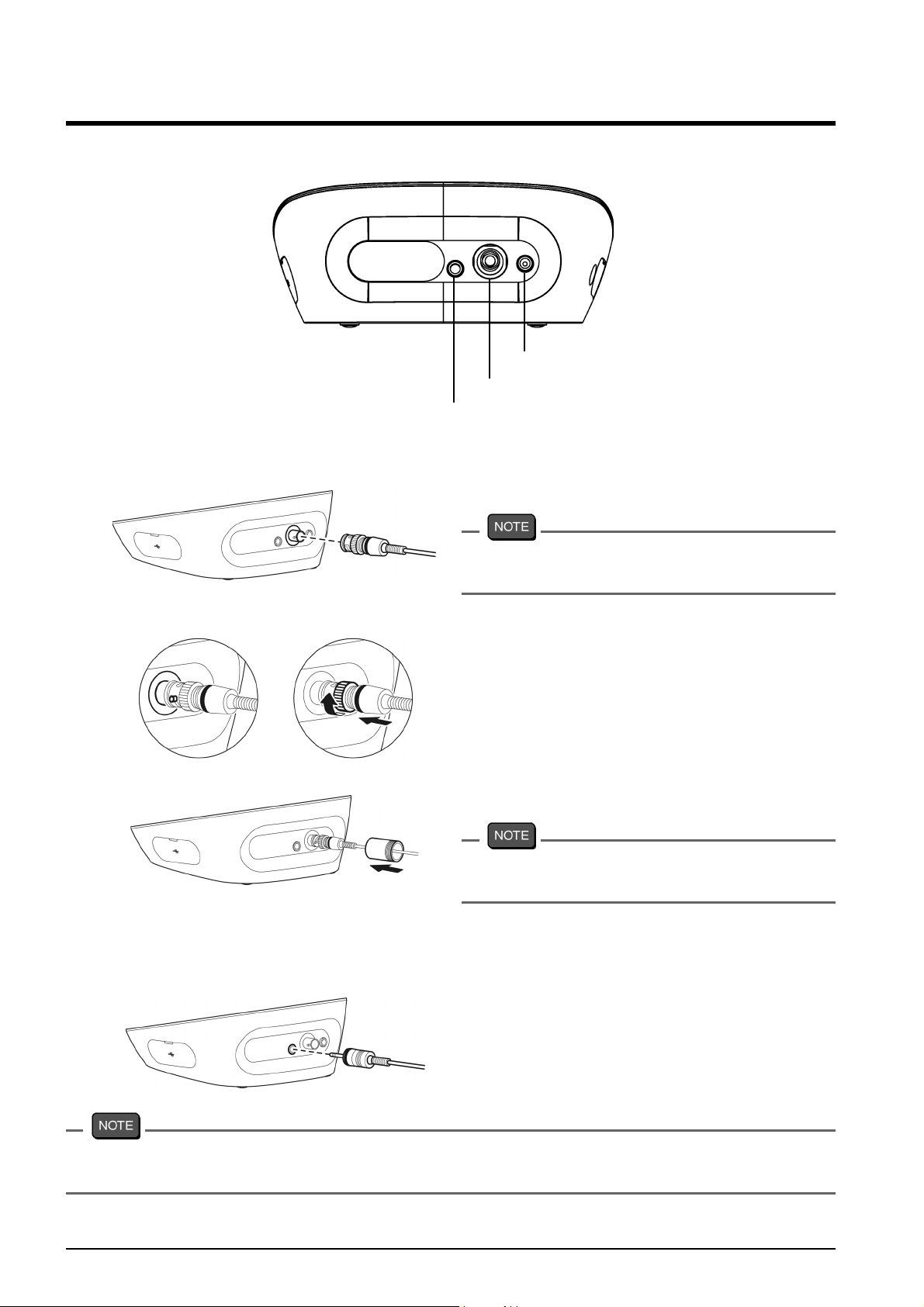
1.6 Connecting the Electrode
1.6.1 Electrode Connector
CH1 reference electrode
CH1 measurement electrode
CH1 for temperature electrode
1. Insert the groove of electrode connector
by fitting with the connector socket pin
of the instrument.
1.6.2 Temperature Connector
Do not insert it with force when the pin
and groove are misaligned.
2. Turn the electrode connector to the right
along the groove to plug the connector.
3. Put the connector cover on the
connector.
Just push the cover on the instrument.
Do not screw in it.
1. Insert the temperature connector into
the jack socket on the instrument.
If the temperature connector is unconnected or the connection is wrong, the MTC set
temperature is displayed as the liquid temperature.
12 HORIBA
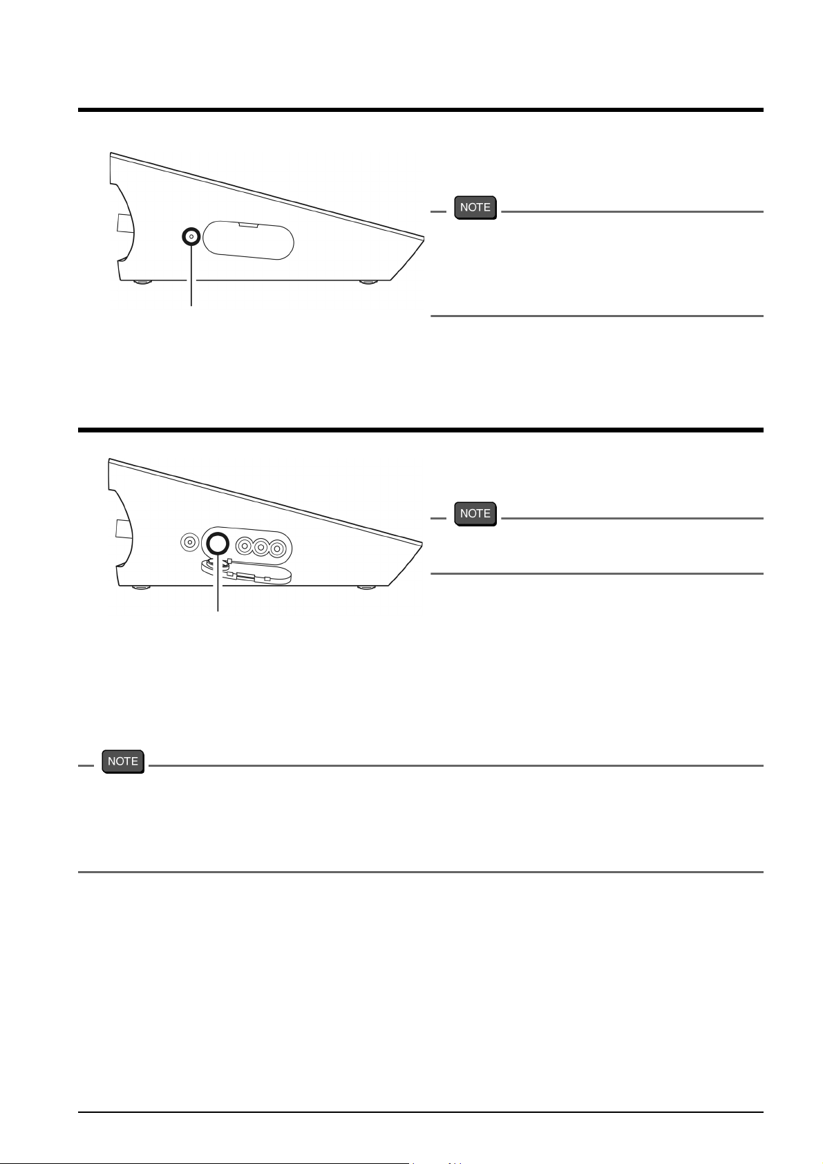
1.7 Connecting the Power Source
AC adapter connector
1.8 Connecting the Printer
Chapter 1 OVERVIEW
1. Insert the AC adapter cable by fitting
with the connector socket of in the
instrument.
・ Do not insert the cable with force when
the connectors do not match.
・ Attach the provided ferrite core to the
AC adapter cable.
1. Insert the printer cable by fitting with the
connector socket of in the instrument.
Do not insert the cable with force when
the connectors do not match.
Printer connector
The following printer is available.
Printer
CITIZEN CBM-910-24RJ120 V: plain paper type (Parts No.: 3014030146)
CITIZEN CBM-910-24RJ230 V: plain paper type (Parts No.: 3014030147)
Optional printer cable (Parts No.: 3014030148) is required.
・ Make sure to use the appropriate cable for the printer.
・ Make sure to power OFF the instrument before connecting a printer.
・ When you do not connect a printer with the instrument, disconnect the printer cable and
put the rubber cap firmly on the connector socket on the instrument.
● Setting the Printer
Refer to the instruction manual of the printer for settings and operations of the printer.
1. Set the DIP switch No. 6 to ON and No. 7 to OFF, and then set printer paper and ink
ribbon. Keep the LF key held down.
2. Keep the SEL key held down.
The printer prints output when the SEL key is being pressed.
F-72 13

Chapter 1 OVERVIEW
1.9 Connecting the Personal Computer
USB connector for personal computer communication
・ Use designated cables to connect with a personal computer.
Designated cable
Parts name: USB cable (1 m)
Parts No.: 3200373941
・ Make sure that the transfer formats of the measuring instrument and personal computer
are same. Otherwise, communication may fail due to a communication error or the
online mode start failure. If you change the transfer formats, power OFF both of the
instrument and the personal computer once, and then turn ON them again.
・ For the details of communication commands, register with our website and see the free
download page of manuals.
14 HORIBA
Chapter 1 OVERVIEW
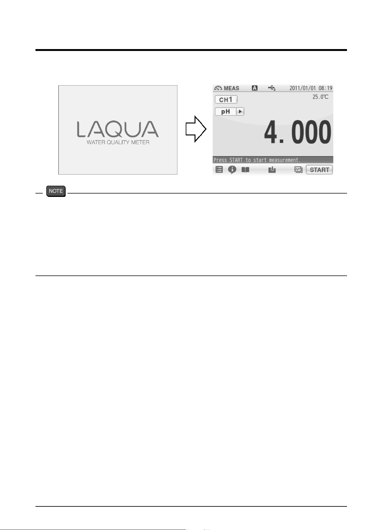
1.10 Turn ON the Power
Press and hold the POWER key for 2 seconds or longer.
Following the startup screen, the MEAS screen will be displayed.
・ The POWER key does not work for 10 seconds after the AC adapter is connected.
Wait for a while after connecting AC adapter.
・ If the following message appears on the screen during operation, disconnect the AC
adapter and then connect it again and power ON the instrument.
==F-7X series memory manager==
Exception failure occurred.
Please detach AC adapter and restart.
F-72 15
Chapter 2 Before Measurement (Meter SET)
Chapter 2 Before Measurement (Meter SET)
This chapter explains the procedures of the instrument condition setting, which should be
performed before measurement.
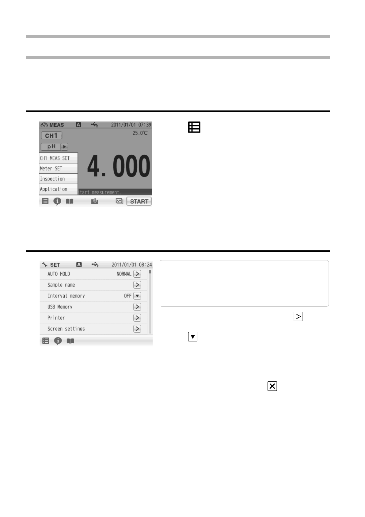
2.1 Meter SET Screen
1. Tap and tap Meter SET.
Meter SET items are displayed.
You will see the remaining items by dragging.
2. Select items and set the conditions.
The setting procedures for each item are
explained below.
2.2 Auto Hold Setting
In the AUTO HOLD mode, the instrument judges
potential stability automatically to the
measurement values. This instrument allows
you to select one among the 6 type criteria of
potential stability.
1. Change the auto hold settings, tap on the
right of the AUTO HOLD item.
2. Tap on the right of the HOLD TYPE item.
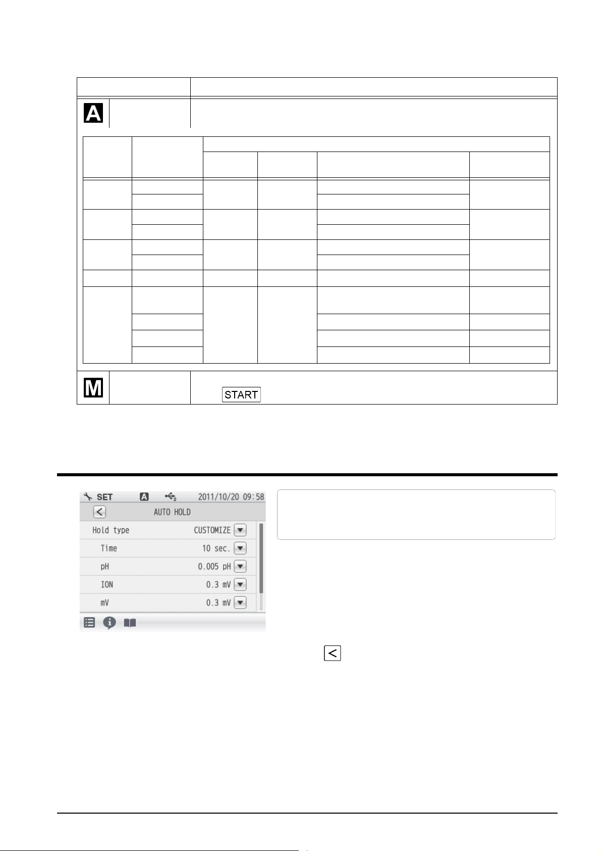
3. Select the measurement stability condition of
the 6 types (EXACT, NORMAL, BRIEF, TIME,
CUSTOMIZE, Manual) in the AUTO HOLD
selection screen.
To cancel the operation, tap to return to the
previous screen.
16 HORIBA
Chapter 2 Before Measurement (Meter SET)
Each HOLD condition is described below.
Stability condition Function
Auto hold
Mode
EXACT
NORMAL
BRIEF
TIME Common - - Arbitrarily set at 2 s to 999 s.
CUSTOMI
ZE
Measuring
target
pH
ION, mV, ORP 0.3 mV
pH
ION, mV, ORP 1.0 mV
pH
ION, mV, ORP 3.0 mV
pH
ION Arbitrarily set at 0.1 mV to 60 mV.
mV Arbitrarily set at 0.1 mV to 60 mV.
ORP Arbitrarily set at 0.1 mV to 60 mV.
In the AUTO HOLD mode, the instrument judges potential stability
automatically to set the measurement values.
Content
Time (s)
10 2.0
10 2.0
10 2.0
Arbitrary
setting
2 s to 60 s
【10 s】
Temperature
(°C)
2.0
Criteria
0.005 pH (Equivalent to 0.3 mV)
0.015 pH (Equivalent to 1.0 mV)
0.050 pH (Equivalent to 3.0 mV)
Arbitrarily set at 0.001 pH to
0.100 pH.
Determine an end point manually.
Manual hold
(Tap to hold it.)
【Default】
Default setting of
auto hold
【10 s】
【0.005 pH】
【0.3 mV】
【0.3 mV】
【0.3 mV】
2.3 Custom Setting
We will explain the procedures of CUSTOMIZE
setting taking the AUTO HOLD item as an
example.
1. Select the CUSTOMIZE of the Hold type to set
the stability condition time and the stability
condition value.
2. Use the numeric-key screen to enter
measurement variations as HOLD criteria for
each measurement item.
Tap to return to the previous screen.
F-72 17
Chapter 2 Before Measurement (Meter SET)
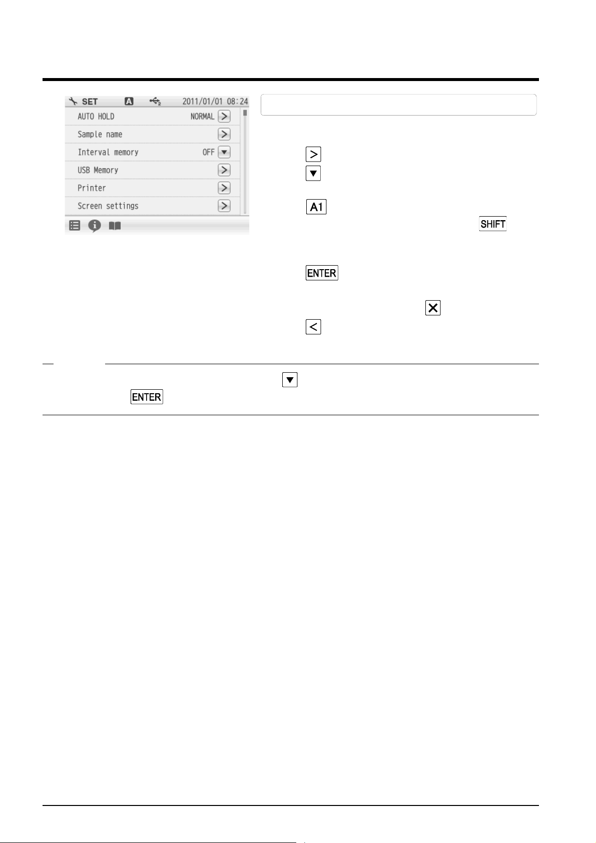
2.4 Sample Name Setting
1. Tap on the right of the Sample name item.
2. Tap on the right of the item in the CH1 or the
3. Tap to switch the keyboard entry screen of
4. Tap .
You can set sample names for CH1.
CH2 to enter the sample name.
Alphabet --> Numerical/Symbol. Tap to
input in lower-case alphabets.
Up to 10 characters can be input.
The setting applies.
To cancel the settings, tap .
Tap to return to the previous screen.
HINT!
To delete a registered sample name, tap on the right of the sample name, enter nothing, and tap .
18 HORIBA
 Loading...