

Horiba LAQUA F-71 Operating Manual

Instruction Manual
pH meter
F-71
表紙は別途デザインの表紙とする

䂓
Preface
䂓
䂓
Thank you for purchasing one of the F-71 pH meters.
This meter has a large-sized LCD display, which enables to use the varied
functions by simple operations, and especially will be convenient to use in
laboratory.
Carefully read this manual before using the meter.
Warranty and Responsibility
Your meter is covered by HORIBA, Ltd. warranty for a period of one (1) year,
under normal use. Although unlikely, if any trouble attributable to HORIBA, Ltd.
should occur during this period, necessary exchange or repairs shall be
conducted by HORIBA, Ltd., free of charge. The warranty does not cover the
following:
• Any trouble or damage attributable to actions or conditions specifically
mentioned to be avoided in the operation manuals
• Any trouble or damage attributable to use of the meter in ways or for
purposes other than those described in the operation manuals
• If any repairs renovations, disassembly, etc. are performed on this meter
by any party other than HORIBA, Ltd. or a party authorized by HORIBA,
Ltd.
• Any alteration to the external appearance of this meter attributable to
scratches, dirt, etc. occurring through normal use
• Wear and tear to parts, the exchange of accessories, or the use of any
parts not specified by HORIBA, Ltd.
HORIBA, LTD. SHALL NOT BE LIABLE FOR ANY DAMAGES RESULTING
FROM ANY MALFUNCTIONS OF THE PRODUCT, ANY ERASURE OF DATA,
OR ANY OTHER USES OF THE PRODUCT.
Unauthorized reprinting or copying of this
operation manual
No unauthorized reprinting or copying of all or part of this operation manual is
allowed. The utmost care has been used in the preparation of this operation
manual. If, however, you have any questions or notice any errors, please contact
the HORIBA customer service center printed on the back cover of this operation
manual.
Copyright © HORIBA, Ltd. 2011
ع
Conformable Directive
٨
٨
This equipment conforms to the following directives and standards:
Directives: The EMC Directive 2004/108/EC
Standards: [the EMC Directive] EN61326-1:2006
Installation Environment
This product is designed for the following environment.
- Overvoltage category II
- Measurement category I
WARNING: Do not use the equipment for measurements within
measurement categories II, III and IV.
REGULATIONS
The Low Voltage Directive 2006/95/EC
Class B, Basic requirements
[the Low Voltage Directive] EN61010-1:2010(Ed.3.0)
Information on Disposal of Electrical and Electronic Equipment and
Disposal of Batteries and Accumulators
The crossed out wheeled bin symbol with underbar shown on the
product or accompanying documents indicates the product requires
appropriate treatment, collection and recycle for waste electrical and
electronic equipment (WEEE) under the Directive 2002/96/EC, and/or
waste batteries and accumulators under the Directive 2006/66/EC in
the European Union.
The symbol might be put with one of the chemical symbols below. In
this case, it satisfies the requirements of the Directive 2006/66/EC for
the object chemical.
This product should not be disposed of as unsorted household waste.
Your correct disposal of WEEE, waste batteries and accumulators will
contribute to reducing wasteful consumption of natural resources, and
protecting human health and the environment from potential negative
effects caused by hazardous substance in products.
Contact your supplier for information on applicable disposal methods.
REGULATIONS
I

ع
FCC Rules
٨
WARNING
REGULATIONS
Any changes or modifications not expressly approved by the party
responsible for compliance shall void the user's authority to operate the
equipment.
This equipment has been tested and found to comply withthe limits for
a Class A digital device, pursuant to part 15 of the FCC Rules. These
limits are designed to provide reasonable protection against harmful
interference when the equipment is operated in a commercial
environment. This equipment generates, uses, and can radiate radio
frequency energy and, if not installed and used in accordance with the
instruction manual, may cause harmful interference to radio
communications.
Operation of this equipment in a residential area is likely to cause
harmful interference in which case the user will be required to correct
the interference at his own expense.
II
SAFETY OPERATION
ع
٨
٨
Hazard Classification and Warning Symbols
Warning messages are described in the following manner. Read the
messages and follow the instructions carefully.
Hazard classification
This indicates an imminently hazardous situation which, if not
avoided, will result in death or serious injury. This signal word
is to be limited to the most extreme situations.
This indicates a potentially hazardous situation which, if not
avoided, could result in death or serious injury.
This indicates a potentially hazardous situation which, if not
avoided, may result in minor or moderate injury. It may also be
used to alert against unsafe practices.
Without safety alert indication of hazardous situation which, if
not avoided, could result in property damage.
Warning symbols
SAFETY OPERATION
Description of what should be done, or what should be followed
Description of what should never be done, or what is prohibited
III
ع
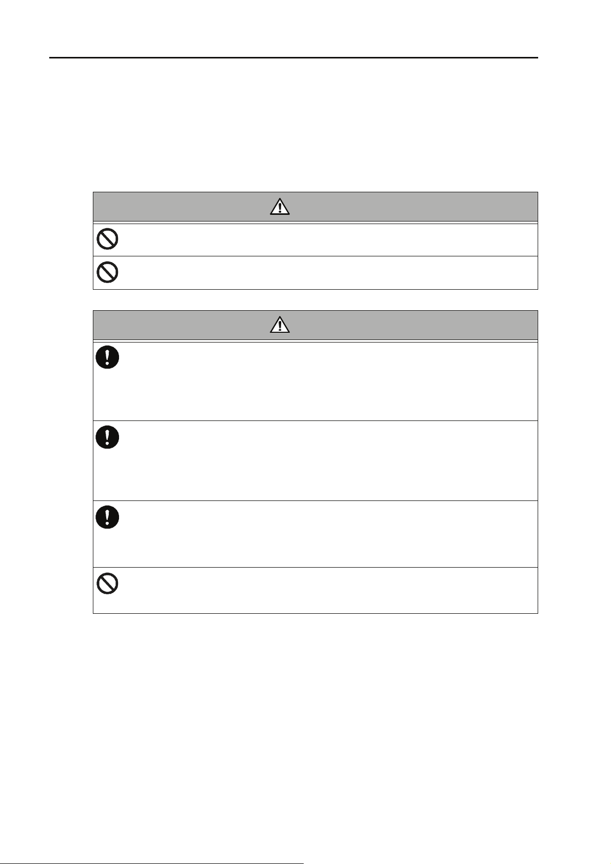
Safety Precautions
This section provides precautions to enable you to use the product
safely and correctly and to prevent injury and damage. The terms of
DANGER, WARNING, and CAUTION indicate the degree of imminency
and hazardous situation. Read the precautions carefully as it contains
important safety messages.
Do not use an unspecified AC adapter.
Otherwise, it may heat up or be ignited resulting in a fire or an accident.
Do not disassemble or modify the meter.
Otherwise, it may heat up or be ignited resulting in a fire or an accident.
SAFETY OPERATION
WARNING
CAUTION
Harmful chemicals
Some ion electrodes are used with hazardous standard solutions. Handle them
with care.
If the internal solution comes in contact with the skin, wash it off immediately. If it
gets into eyes, flush with plenty of water and then consult a doctor.
Harmful chemicals
The internal solution of an electrodes is highly concentrated potassium chloride
(3.33 mol/L KCl).
If the internal solution comes in contact with the skin, wash it off immediately. If it
gets into eyes, flush with plenty of water and then consult a doctor.
Broken glass
Broken glass may cause injury.
The outer tube and tip of an electrode are made of glass.
Handle them with care.
Do not use the cable of serial communication, USB, or AC adapter under wet or
humid conditions.
Otherwise, it may cause an fire, electric shock, or breakage.
IV

SAFETY OPERATION
ع
٨
٨
٨
٨
Product Handling Information
Operational Precautions
٨
Do not drop, crash, or give any physical impact on the instrument.
٨
Do not immerse the instrument into alcohol, organic solvent, strong
acid, strong alkaline, or the like. The instrument body contains ABS
resin, acrylic resin, and some rubber parts.
٨
If the instrument is dropped into water or gets wet, wipe it using soft
cloth. Do not heat to dry it with a hair-dryer (or the like).
٨
Use fingers to press the operation keys or the touch panel.
Do not use a hard object like a metal stick or rod.
٨
Be careful not to let water into the instruction inside.
The instrument is not water-proof.
٨
To disconnect an electrode or interface cable, hold the connector and
pull it off. If you pull at the cable, it may cause a breakage.
٨
The touch panel is capacitance-type. Make sure to turn OFF the
power before cleaning the panel. If you wipe it with the power ON, it
may cause instrument malfunction.
٨
RS-232C or USB communication between the instrument and a personal computer may fail because of environmental conditions, such
as (radio/electromagnetic) noise.
Environmental conditions for use and storage
٨
Temperature: 0qC to 45qC
٨
Humidity: under 80% in relative humidity and free from
condensation
Avoid the following conditions:
٨
Dusty environment
٨
Strong vibration
٨
Direct sunlight
٨
Corrosive gas environment
٨
Close to an air-conditioner
٨
Direct wind
Transportation
When transporting the instrument, repackage it in the original package
box. Otherwise, it may cause instrument breakage.
Disposal
Standard solution used for the calibration must be under neutralized
before the disposal. As for the disposal of the meter, treat it as an
industrial waste.
V

MANUAL INFORMATION
ع
Description in This Manual
This mark indicates the operation requires a special care and attention.
This mark indicates to which the reader should go for reference.
HINT!
This mark indicates reference information.
MANUAL INFORMATION
VI

CONTENTS
Chapter 1 About the F-71 . . . . . . . . . . . 1
Chapter 2 Information of the F-71 . . . . 2
2.1 Measurement Items . . . . . . . . . . . . . . . . . . . . . . . 2
2.2 Packing List . . . . . . . . . . . . . . . . . . . . . . . . . . . . . . 2
2.3 Names and Functions . . . . . . . . . . . . . . . . . . . . . 3
2.3.1 Names of Each Part . . . . . . . . . . . . . . . . . . . . . . . . . . 3
2.3.2 Display . . . . . . . . . . . . . . . . . . . . . . . . . . . . . . . . . . . . 4
2.3.3 Operation Key . . . . . . . . . . . . . . . . . . . . . . . . . . . . . . 5
2.4 Measurement (MEAS) Flow Chart . . . . . . . . . . . . 6
2.5 Setting (SET) Flow Chart . . . . . . . . . . . . . . . . . . . 7
2.6 Data (DATA) Flow Chart . . . . . . . . . . . . . . . . . . . . 8
Chapter 3 Basic Operation . . . . . . . . . . 9
3.1 Preparation . . . . . . . . . . . . . . . . . . . . . . . . . . . . . . 9
3.1.1 Assembling the Electrode Stand . . . . . . . . . . . . . . . . 9
3.1.2 Electrode Connection . . . . . . . . . . . . . . . . . . . . . . . . 10
3.1.3 Connecting the Power Source . . . . . . . . . . . . . . . . . 11
3.1.4 Connecting and Setting the Printer . . . . . . . . . . . . . 12
3.1.5 Connecting the Personal Computer . . . . . . . . . . . . . 13
3.2 Settings . . . . . . . . . . . . . . . . . . . . . . . . . . . . . . . . 14
3.2.1 pH Standard Solution Setting . . . . . . . . . . . . . . . . . . 14
3.2.2 Temperature Compensation Function Setting . . . . . 16
3.2.3 Auto Data Memory Setting . . . . . . . . . . . . . . . . . . . . 18
3.2.4 pH Calibration Interval Setting . . . . . . . . . . . . . . . . . 19
3.2.5 Sample ID Setting . . . . . . . . . . . . . . . . . . . . . . . . . . 21
3.2.6 Auto Printer Setting . . . . . . . . . . . . . . . . . . . . . . . . . 22
3.2.7 Maintenance . . . . . . . . . . . . . . . . . . . . . . . . . . . . . . . 23
3.3 Calibration . . . . . . . . . . . . . . . . . . . . . . . . . . . . . . 38
3.3.1 pH Calibration . . . . . . . . . . . . . . . . . . . . . . . . . . . . . . 38
3.3.2 Calibration Value Printing . . . . . . . . . . . . . . . . . . . . . 47
3.4 Measurement . . . . . . . . . . . . . . . . . . . . . . . . . . . . 48
3.4.1 Measurement Value Hold . . . . . . . . . . . . . . . . . . . . . 48
VII

CONTENTS
3.4.2 Measurement Items Changing . . . . . . . . . . . . . . . . . 49
3.4.3 Auto Data Memory . . . . . . . . . . . . . . . . . . . . . . . . . . 49
3.4.4 Measurement Value Printing . . . . . . . . . . . . . . . . . . 50
3.5 Data Operation . . . . . . . . . . . . . . . . . . . . . . . . . . 52
3.5.1 Data Memory of Measurement Value . . . . . . . . . . . 52
3.5.2 Memory Data Display . . . . . . . . . . . . . . . . . . . . . . . . 53
3.5.3 Memory Data Printing . . . . . . . . . . . . . . . . . . . . . . . 54
3.5.4 Calibration History Display . . . . . . . . . . . . . . . . . . . . 55
3.5.5 Calibration History Printing . . . . . . . . . . . . . . . . . . . . 56
3.5.6 pH Check History Display . . . . . . . . . . . . . . . . . . . . 58
3.5.7 pH Check Data Printing . . . . . . . . . . . . . . . . . . . . . . 59
Chapter 4 Maintenance and
Troubleshooting . . . . . . . . 60
4.1 pH (ORP) Electrode Maintenance . . . . . . . . . . . 60
4.2 Troubleshooting . . . . . . . . . . . . . . . . . . . . . . . . . 64
4.2.1 Error Message Chart . . . . . . . . . . . . . . . . . . . . . . . . 64
4.2.2 More Troubleshooting . . . . . . . . . . . . . . . . . . . . . . . 70
Chapter 5 Specifications . . . . . . . . . . 76
5.1 Specifications . . . . . . . . . . . . . . . . . . . . . . . . . . . 76
5.2 Default Settings . . . . . . . . . . . . . . . . . . . . . . . . . 77
5.3 Options . . . . . . . . . . . . . . . . . . . . . . . . . . . . . . . . 78
VIII

Chapter 1 About the F-71
Chapter 1 About the F-71
The desktop type pH meter F-71 is optimized for
laboratory measurement, and allows you to measure pH
and ORP.
It provides a comfortable measurement environment
with the design easy to wipe clean without roughness on
the surface, and the free-standing electrode stand and
the custom LCD for ease of measurement.
F-71 1
Chapter 2 Information of the F-71
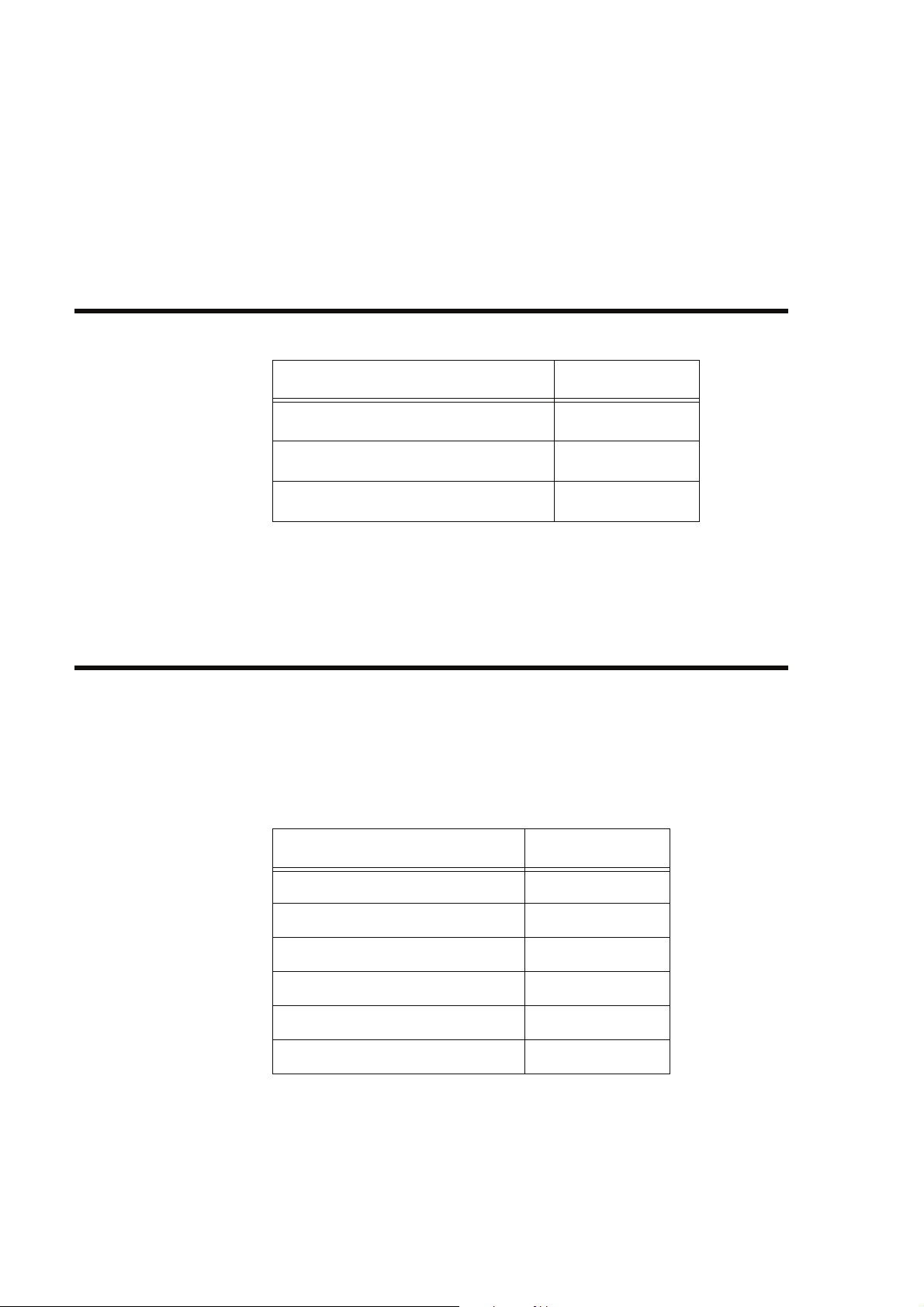
2.1 Measurement Items
Chapter 2
Information of the F-71
2.1 Measurement Items
Measurement item F-71
pH
ORP (mV)
Temperature
2.2 Packing List
The F-71’s package includes the following.
Electrodes are required for the measurement in addition
to this package. If you want to buy an electrode, contact
HORIBA sales representative.
Main unit 1
Electrode stand 1
Instruction Manual 1
Quick Manual 1
AC adapter 1
Ferrite core 1
Product Quantity
2HORIBA
2.3 Names and Functions
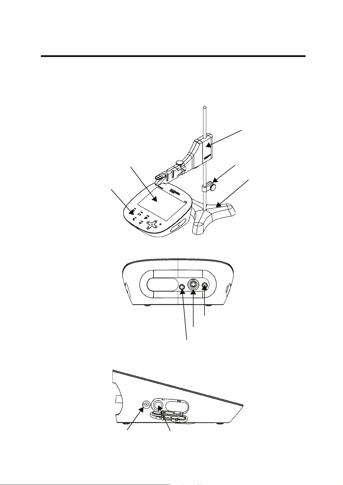
2.3.1 Names of Each Part
Chapter 2 Information of the F-71
2.3 Names and Functions
Stand arm
Display
Operation key
Stopper
Stand base
CH1 reference electrode
CH1 measurement electorode
CH1 temperature electrode
AC adapter connector
Printer connector
F-71 3
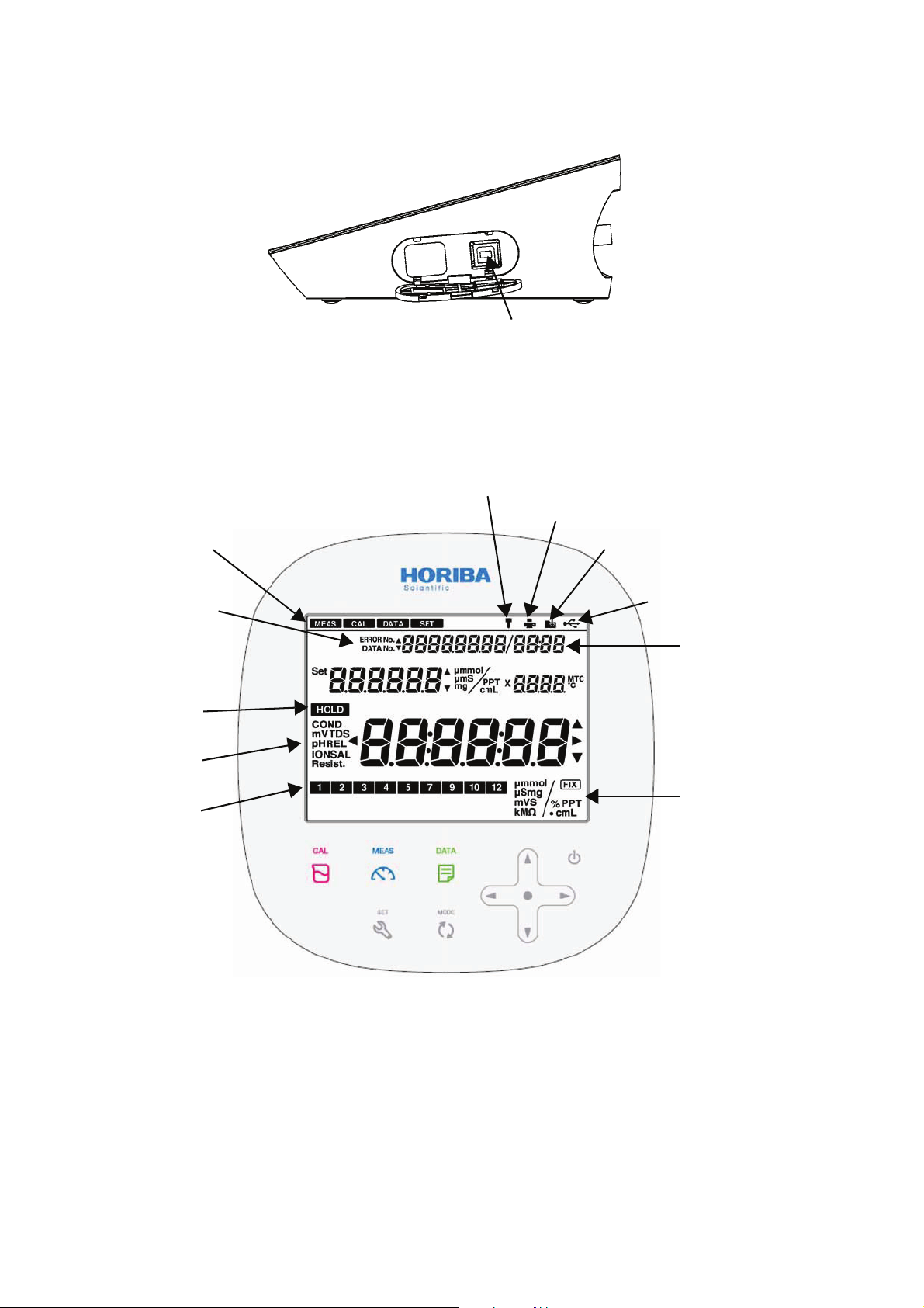
Chapter 2 Information of the F-71
2.3 Names and Functions
Connector for USB communication with a personal computer
2.3.2 Display
Electroload status icon
Setting mode
Error No.,
Data No.,
Date
HOLD
indicator
Measuring
composition
Calibration
date
Printer connecting icon
Data memory icon
USB icon
Temperature
Measurement
unit
4HORIBA
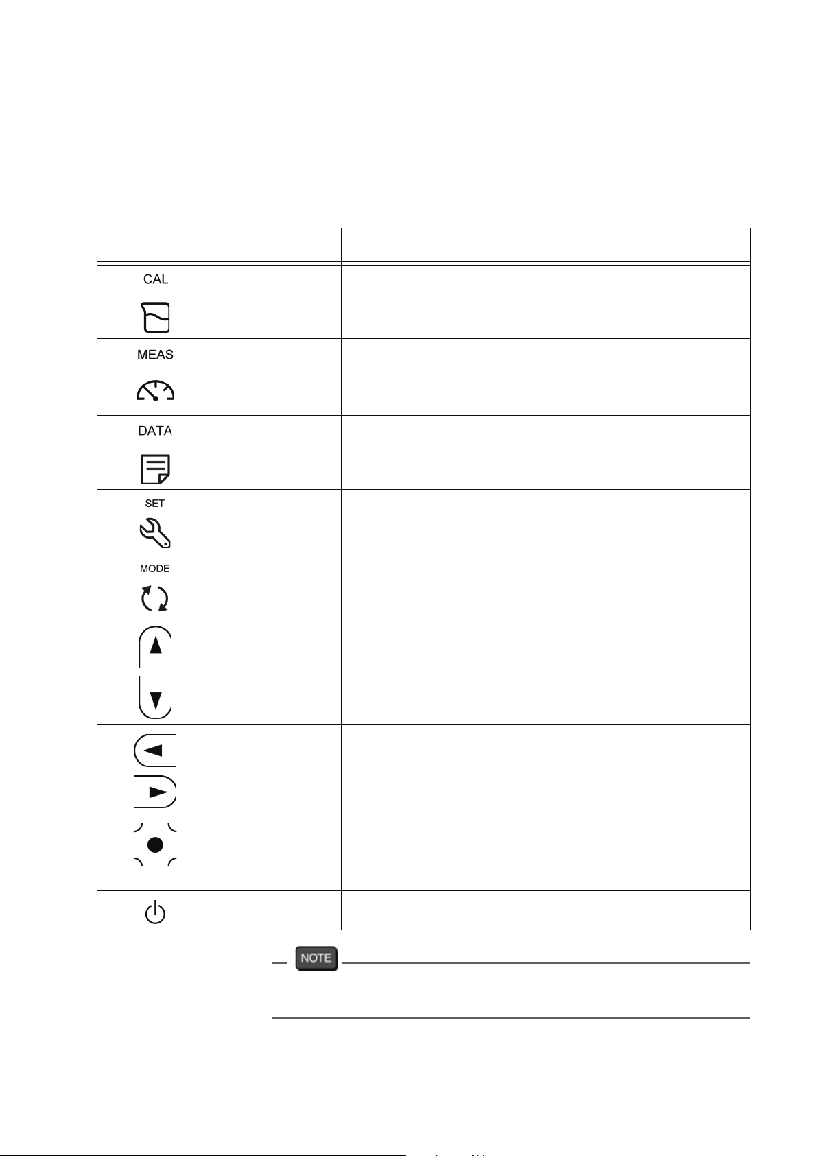
2.3.3 Operation Key
This instrument employs capacitance switches.
You can not operate them with thick gloves. Operate
them with bare hands or thin rubber gloves.
Operation key Function
CAL key Starts/stops calibration or enters the
MEAS key Starts/stops measurement or enters the mea-
DATA key Enters the data operation mode.
Chapter 2 Information of the F-71
2.3 Names and Functions
calibration mode.
surement mode.
Applies the setting values of the setting mode.
Printouts calibration value.
SET key Enters the setting mode.
Cancels the setting values of the setting mode.
MODE key Toggles the measurement items.
䂥 key
䂯 key
Increases the values.
Decreases the values.
Switches the setting item.
Switches the CH items.
䂥
key
䂯
Change number of digits, selects functions.
Printouts measurement values. ( key)
ENTER key Settlement, execution, prinout
(except measurement values)
Start/stops automatic data memory.
䂯
POWER key Turns ON or OFF the power.
Press the POWER key for 1 second or longer to turn ON the
power, for 2 seconds or longer to turn OFF the power.
F-71 5
Chapter 2 Information of the F-71
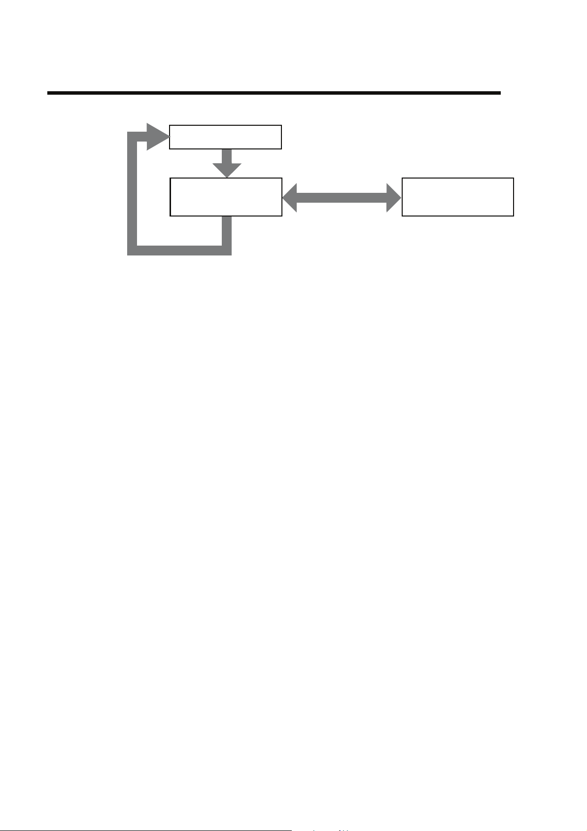
2.4 Measurement (MEAS) Flow Chart
2.4 Measurement (MEAS) Flow Chart
pH measurement
MODE key
ORP measurement
(mV)
MODE key
ORP measurement
(Relative mV)
CAL key
6HORIBA
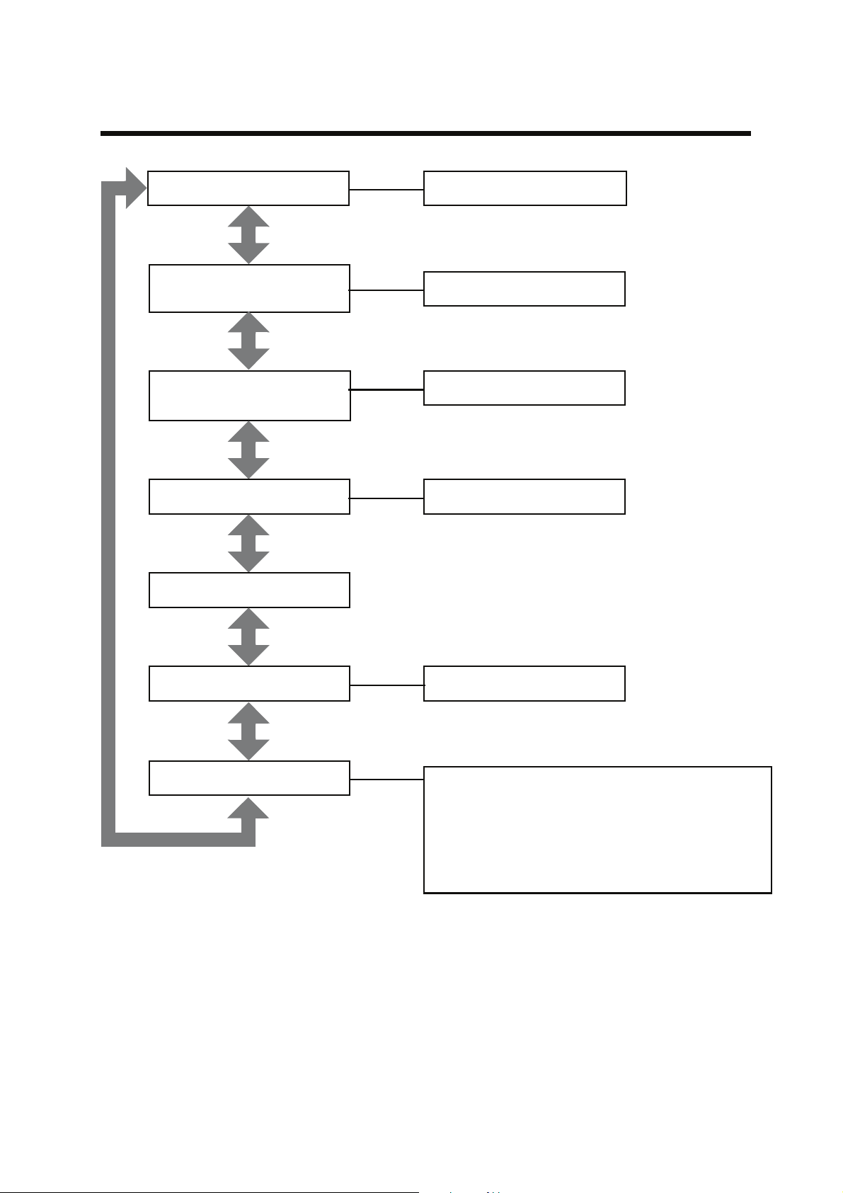
2.5 Setting (SET) Flow Chart
Chapter 2 Information of the F-71
2.5 Setting (SET) Flow Chart
Standard solution setting
䂥䂯 key
Temperature compensation
function setting
䂥䂯 key
Automatic data memory
setting
䂥䂯 key
pH calibration interval setting
䂥䂯 key
Sample ID setting
NIST, USA, CUST
ATC, MTC
ON, OFF
ON, OFF
䂥䂯 key
Automatic printout setting
䂥䂯 key
Maintenance
䂥䂯 key
ON, OFF
LCD Check, Printer Test, Auto Power Off Settings, Day and Time Settings, Memory Data
Deleting, Calibration Data Deleting, Number of
Memory Data Display, Temperature Calibration, Setting Value Initialization, Password Settings
F-71 7
Chapter 2 Information of the F-71
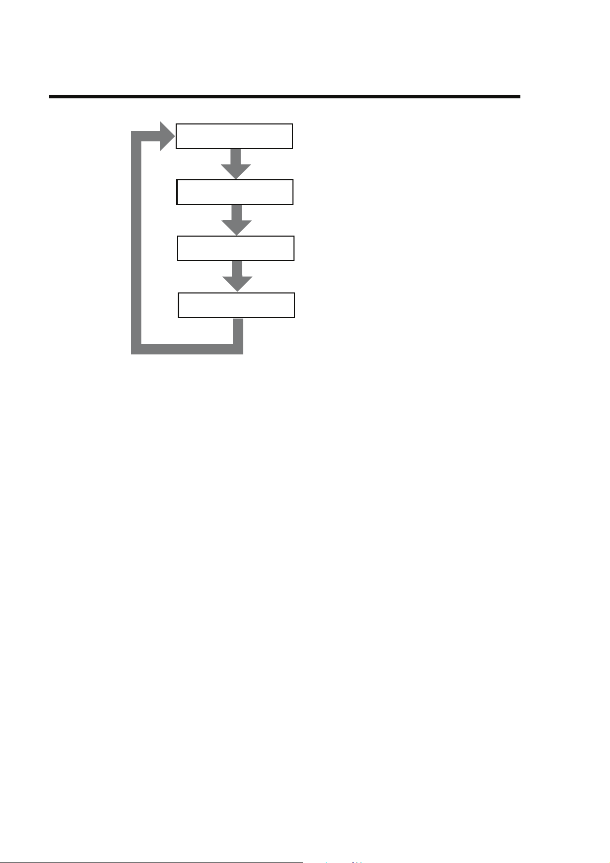
2.6 Data (DATA) Flow Chart
2.6 Data (DATA) Flow Chart
Data memory
䂥䂯 key
Data display
䂥䂯 key
pH calibration data
䂥䂯 key
pH check data
䂥䂯 key
8HORIBA
Chapter 3 Basic Operation
Chapter 3 Basic Operation
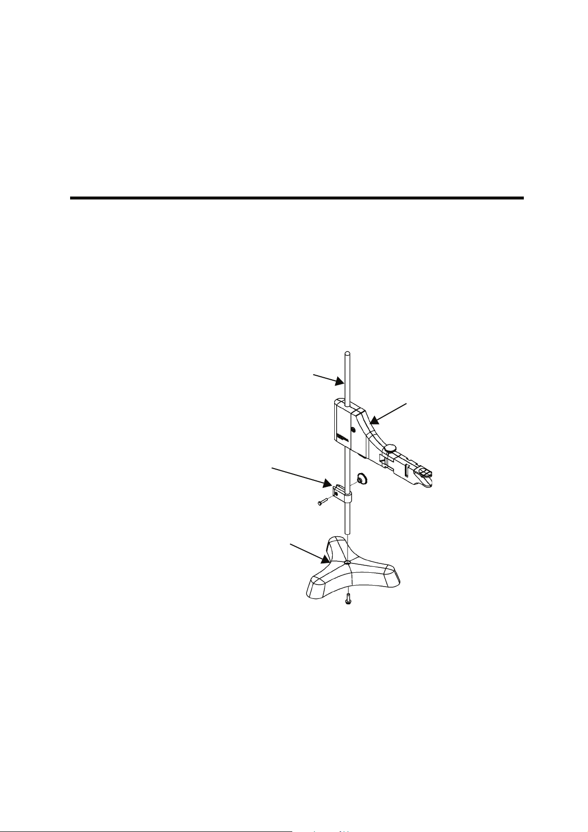
3.1 Preparation
3.1.1 Assembling the Electrode Stand
1. Attach the stand shaft to the stand base.
2. Attach the stopper and the stand arm to the stand
shaft.
3.1 Preparation
Stand shaft
Stopper
Stand base
Stand arm
F-71 9
Chapter 3 Basic Operation
䃂
3.1 Preparation
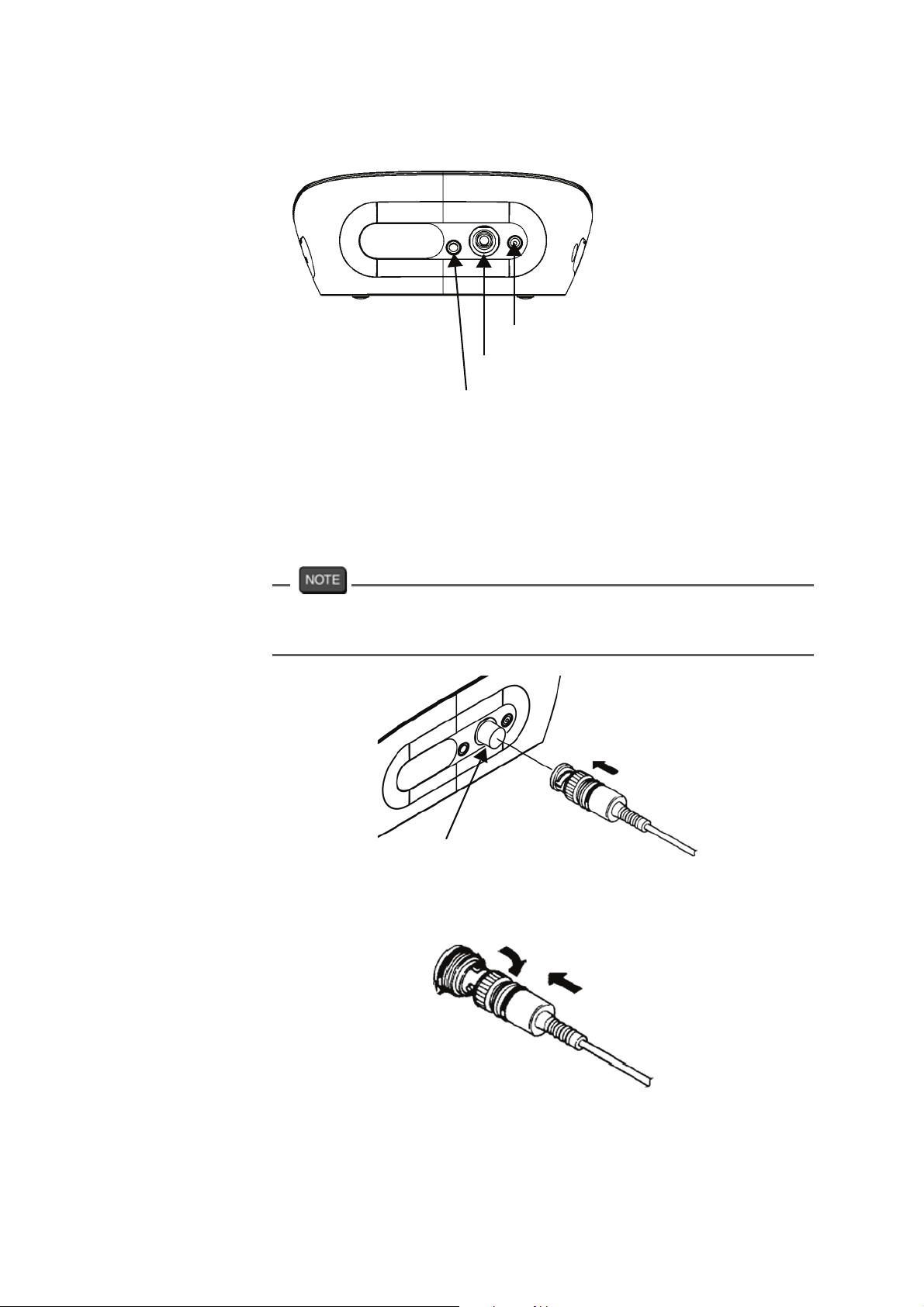
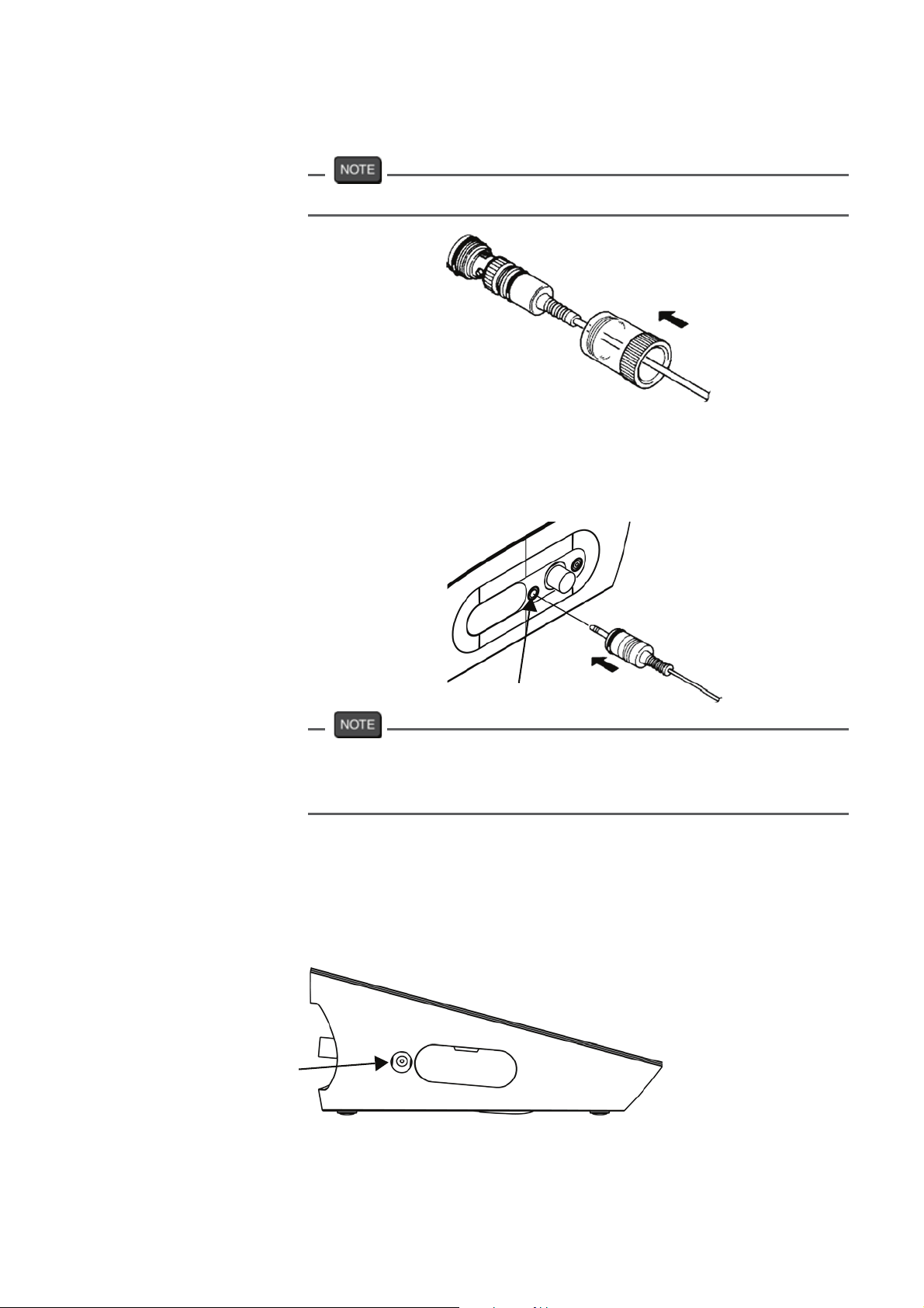
3.1.2 Electrode Connection
Electrode connector
CH1 reference electrode
CH1 measurement electorode
CH1 temperature electrode
1. Insert the groove of electrode plug by fitting it with
the socket pin of the instrument.
If the pin and groove are misaligned, do not insert the
plug with force.
CH1 measurement electrode
2. Turn the electrode connector to the right along the
groove to plug the connector.
10 HORIBA
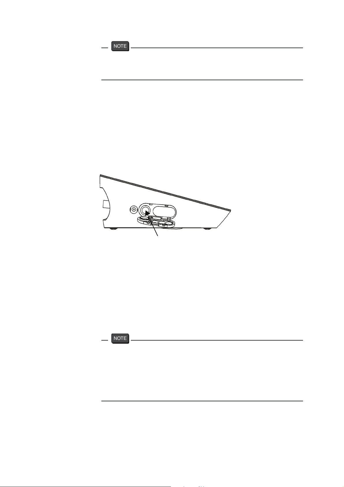
3. Put the connector cover on the connector.
䃂
Just push the cover on the instrument. Do not screw in it.
Temperature connector
1. Insert the temperature connector into the jack
socket on the instrument.
Chapter 3 Basic Operation
3.1 Preparation
CH1 temperature electrode
If the temperature connector is unconnected or the connection is
wrong, the MTC set temperature is displayed as the sample
temperature.
3.1.3 Connecting the Power Source
1. Insert the AC adapter cable by fitting with the
connector socket of in the instrument.
AC adapter connector
F-71 11
Chapter 3 Basic Operation
䃂
3.1 Preparation
䊶 Do not insert the cable with force when the connectors do not
match.
䊶 Attach the provided ferrite core to the AC adapter cable.
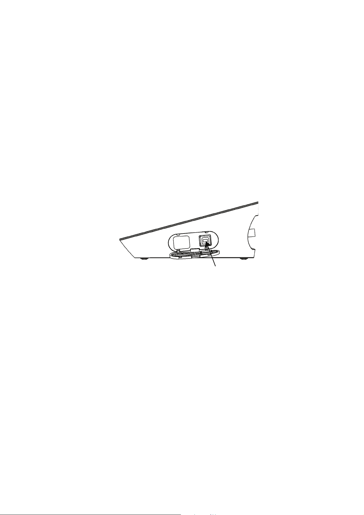
3.1.4 Connecting and Setting the Printer
Connecting the Printer
1. Insert the printer cable by fitting with the connector
socket of the instrument.
Printer connector
The following printer is possible.
Printer
䊶CITIZEN CBM-910-24RJ100-A:
plain paper type (Parts No.: 3014030145)
䊶Optional printer cable (Parts No.: 3014030148) is
required.
䊶 Make sure to use an appropriate cable for the printer.
䊶 Make sure to power OFF the instrument before connecting a
printer.
䊶 When you do not connect a printer with the instrument,
disconnect the printer cable and put the rubber cap firmly on
the connector sockets of the instrument.
12 HORIBA
䃂
Setting the Printer
Refer to the instruction manual of the printer for settings
and operations of the printer.
(1) Set the DIP switch No. 6 to ON and No. 7 to OFF,
and then set printer paper and ink ribbon. Keep the
LF key held down
(2) Keep the SEL key held down.
The printer prints output when the SEL key is being
pressed.
3.1.5 Connecting the Personal Computer
Chapter 3 Basic Operation
3.1 Preparation
Personal computer communication connector
䊶Use proprietary cables to connect with a personal
computer.
Proprietary cable
Parts name: USB cable (1 m)
Parts No.: 3200373941
䊶Make sure that the transfer formats of the measuring
instrument and personal computer are same.
Otherwise, communication may fail due to a
communication error or the online mode start failure.
If you change the transfer formats, power OFF both of
the instrument and the personal computer once, and
then turn on them again.
䊶For the details of communication commands, register
with our website and see the free download page of
manuals.
F-71 13
Chapter 3 Basic Operation
3.2 Settings
3.2 Settings
This section describes the procedures of the instrument
condition settings for measurement, calibration, and
maintenance.
The settings apply when you press the MEAS key to
return to the measurement screen.
If you press the SET key during setting or after pressing
the ENTER key, the settings are cancelled.
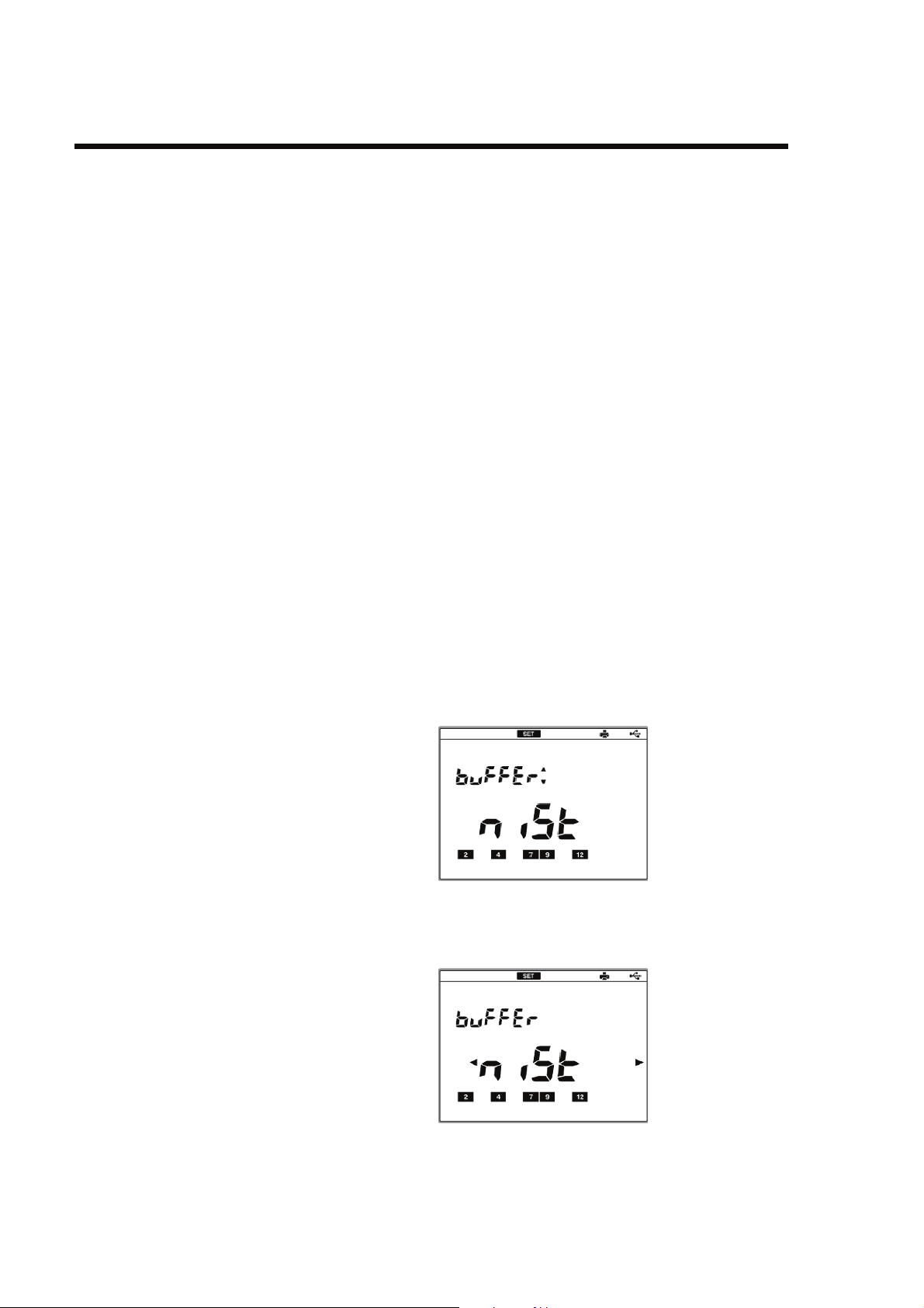
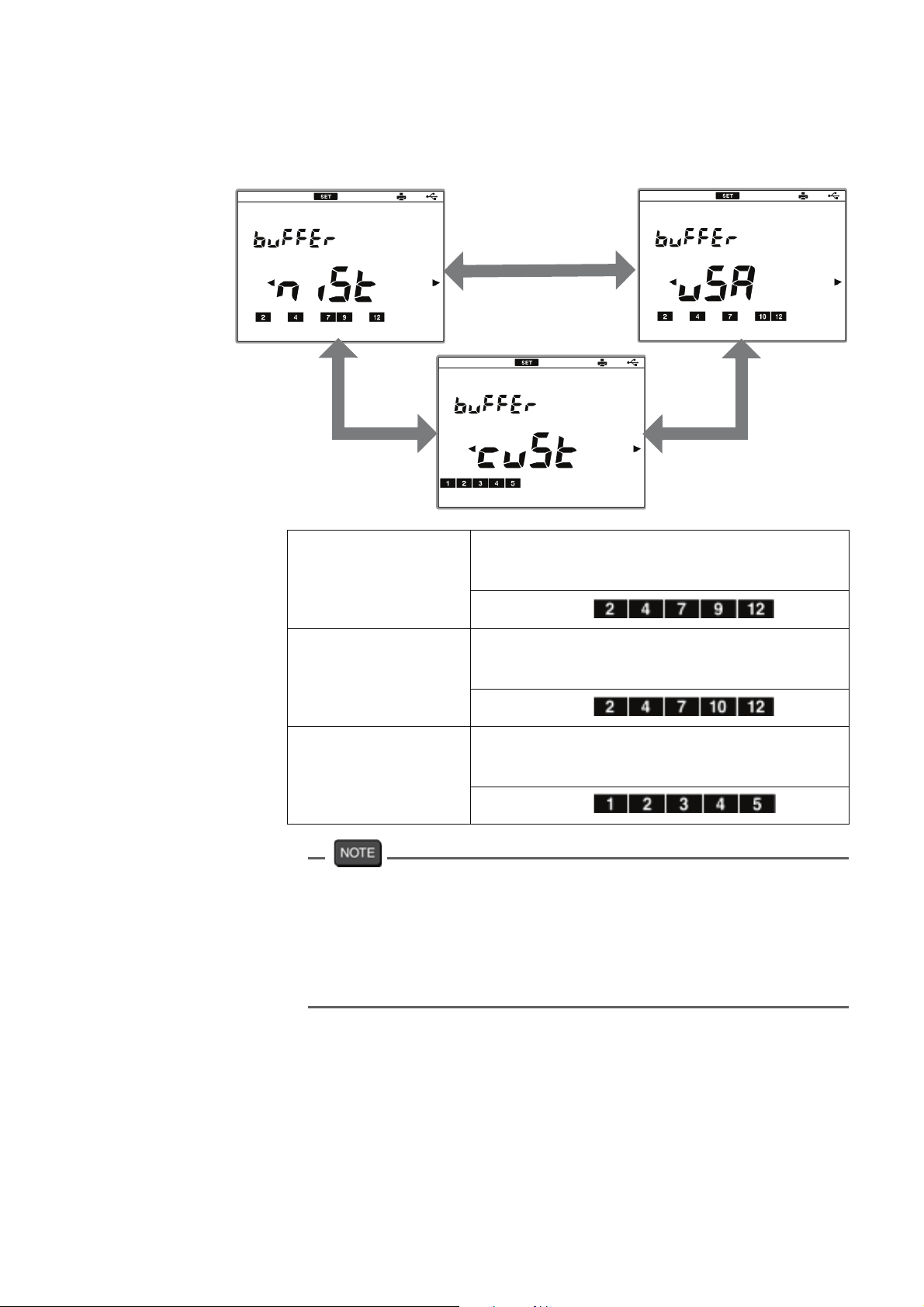
3.2.1 pH Standard Solution Setting
There are 3-type settings of standard solutions used for
calibration; NIST, USA, and CUST.
NIST is selected initially for pH standard solutions.
This setting is possible only for CH1.
1. Press the SET key on the measurement screen is
displayed to enter the pH standard solution setting
screen.
2. Press the ENTER key to enter the pH standard
solution change screen
14 HORIBA
Chapter 3 Basic Operation
3.2 Settings
3. Press the or key to change NIST, USA, and
䂥
䂯
CUST, and press the ENTER key.
NIST
specification
(NIST)
When using a standard solution of
interior specification
Bottle mark
US specification
(USA)
When using a standard solution of the
USA specification
Bottle mark
Customized
specification
(CUST)
The calibration value of the pH7 standard solution differs between
NIST and USA.
NIST specification: pH6.865 (at 25qC)
US specification: pH7.000 (at 25qC)
When you use NIST standard solution for calibration, make sure
to set NIST here.
When the user’s exclusive standard
solution
Bottle mark
F-71 15
Chapter 3 Basic Operation
3.2 Settings
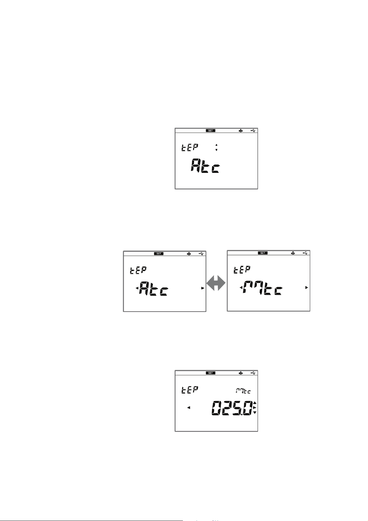
3.2.2 Temperature Compensation Function Setting
You can perform temperature compensation for pH
electrode outputs.
1. Press the SET key on the measurement screen,
and press the 䂯 key to enter the temperature
compensation function setting screen.
2. Press the ENTER key to enter the temperature
compensation function change screen.
3. Press the or key to change ATC or MTC, and
press the ENTER key.
䂥
4. If you select MTC, press the or key to select
a digit and press the 䂥 or 䂯 key to change the
value, and then press the ENTER key.
Setting range: 0qC to 100qC
䂯
䂥
䂯
16 HORIBA

Chapter 3 Basic Operation
3.2 Settings
ATC
In Automatic Temperature Compensation (ATC), the
instrument detects the solution temperature. When the
temperature sensor is connected, the current temperature of the solutions is displayed automatically. If the
sensor is not connected, the set value for MTC (default:
25qC) is displayed.
MTC
In Manual Temperature Compensation (MTC), the temperature sensor of the electrode is not used, and the
solution temperature is entered manually.
F-71 17
 Loading...