

horiba HP-200 Instruction Manual

Industrial pH Meter
HP-200
Instruction Manual
CODE:GZ0000214572

Preface
This manual describes the operation of the Industrial pH Meter, HP-200.
Be sure to read this manual before using the product to ensure proper and safe operation of
the instrument. Also safely store the manual so it is readily available whenever necessary.
Product specifications and appearance, as well as the contents of this manual are subject to
change without notice.
Warranty and Responsibility
HORIBA Advanced Techno, CO., Ltd. warrants that the Product shall be free from defects in
material and workmanship and agrees to repair or replace free of charge, at option of HORIBA
Advanced Techno, CO., Ltd., any malfunctioned or damaged Product attributable to
responsibility of HORIBA Advanced Techno, CO., Ltd. for a period of one (1) year from the
delivery unless otherwise agreed with a written agreement. In any one of the following cases,
none of the warranties set forth herein shall be extended;
z Any malfunction or damage attributable to improper operation
z Any malfunction attributable to repair or modification by any person not authorized by
HORIBA Advanced Techno, CO., Ltd.
z Any malfunction or damage attributable to the use in an environment not specified in this
manual
z Any malfunction or damage attributable to violation of the instructions in this manual or
operations in the manner not specified in this manual
z Any malfunction or damage attributable to any cause or causes beyond the reasonable
control of HORIBA Advanced Techno, CO., Ltd. such as natural disasters
z Any deterioration in appearance attributable to corrosion, rust, and so on
z Replacement of consumables
HORIBA ADVANCED TECHNO, CO., LTD. SHALL NOT BE LIABLE FOR ANY DAMAGES
RESULTING FROM ANY MALFUNCTIONS OF THE PRODUCT, ANY ERASURE OF DATA,
OR ANY OTHER USES OF THE PRODUCT.
Trademarks
Generally, company names and brand names are either registered trademarks or trademarks
of the respective companies.
May, 2010 © 2010 HORIBA Advanced Techno, Co., Ltd.

Regulations
Conformable Directive
This equipment conforms to the following directives and standards:
Directives:
Standards:
Note
When the sensor cable, transmission cable, or relay cable is extended to 30 meters or
more, the surge test in the EMC Directive for CE Marking is not applicable.
J Installation Environment
This product is designed for the following environment.
z Installation Categories II
z Pollution degree 2
FCC Rules
Any changes or modifications not expressly approved by the party responsible for compliance
shall void the user's authority to operate the equipment.
the EMC Directive 2004/108/EC
the Low Voltage Directive 2006/95/EC
[the EMC Directive]
EN61326-1: 2006 Class A, industry
[the Low Voltage Directive] EN61010-1: 2001
J WARNING
This equipment has been tested and found to comply with the limits for a Class A digital
device, pursuant to part 15 of the FCC Rules. These limits are designed to provide reasonable
protection against harmful interference when the equipment is operated in a commercial
environment. This equipment generates, uses, and can radiate radio frequency energy and, if
not installed and used in accordance with the instruction manual, may cause harmful
interference to radio communications.
Operation of this equipment in a residential area is likely to cause harmful interference in
which case the user will be required to correct the interference at his own expense.

For Your Safety
Hazard Classification and Warning Symbols
Warning messages are described in the following manner. Read the messages and follow the
instructions carefully.
Q Hazard classification
This indicates an imminently hazardous situation which, if not avoided, will
result in death or serious injury. This signal word is to be limited to the
most extreme situations.
This indicates a potentially hazardous situation which, if not avoided,
could result in death or serious injury.
This indicates a potentially hazardous situation which, if not avoided, may
result in minor or moderate injury. It may also be used to alert against
unsafe practices. Without safety alert indication of hazardous situation
which, if not avoided, could result in property damage.
Q Warning symbols
Description of what should be done, or what should be followed
Description of what should never be done, or what is prohibited
Safety Precautions
This section provides precautions to enable you to use the product safely and correctly and to
prevent injury and damage. The terms of DANGER, WARNING, and CAUTION indicate the
degree of imminency and hazardous situation. Read the precautions carefully as it contains
important safety messages.
When any load larger than the contact capacity or any induction load (e.g., a motor or a pump) is
used, be sure to connect that load via a power relay that has a rating larger than the load rating.
When the HP-200 may be subject to lightning, install a conductor rod on the output side of the HP-200
and on the side of receiving instruments.
Be sure to connect the grounding terminal (class D grounding) for safety.
Electric shock
Be sure to check that no power is supplied before starting work.
Strong acid
If dilute hydrochloric acid gets into the eye, mucous membrane may be irritated, resulting in the loss of
sight.
WARNING
In handling hydrochloric acid, be sure to use protective goggles, protective gloves, and a protective
mask.
If hydrochloric acid gets into the eye, immediately rinse the eye with a large quantity of water for at
least 15 minutes and then receive medical attention. (When rinsing the eye, well open it with fingers
so that the eyeball and the eyelid can be fully cleaned.)
If hydrochloric acid adheres to your body or clothes, you may get burned. Therefore, immediately
remove the clothes and then rinse off hydrochloric acid with a large quantity of water.
CAUTION
If there is corrosive gas in the installation environment, send clean instrumentation air from the air
purge inlet on the HP-200.
When the HP-200 is OFF, the C-NC contact is short-circuited. Therefore, be careful about the
connection of any load.
Since operation of the HP-200 at any voltage outside the rated range can cause a fault, check the
power supply voltage. Also check that the voltage fluctuation range of the power source falls within
the range of rated voltage ±10%.
The electrode is a glass product, which is broken if it is exposed to an impact, strong force, or the like.
In handling the electrode, therefore, exercise sufficient care.

Product Handling Information
Operational Precautions
Use of the equipment in a manner not specified by the manufacturer may impair the protection
provided by the equipment. And it may also reduce equipment performance.
Therefore, exercise the following precautions:
z Do not press any operation key with the tip of your nail or any pointed thing.
z Do not use organic solvent or the like.
z Do not immerse the HP-200 in dilute hydrochloric acid for long hours.
Disposal of the Product
When disposing of the product, follow the related laws and/or regulations of your country for
disposal of the product.
Manual Information
Description in This Manual
Note
This interprets the necessary points for correct operation and notifies the important points for
handling the unit.
Reference
This interprets the necessary points for correct operation and notifies the important points for
handling the unit.
Tip
This indicates the part of where to refer the information.
Definitions of terms
This document uses the following terms as defined:
Term Definition
Hold down Maintain pressing a key until the indicator turns ON or the display changes.
Press Lightly press a key once.
Flash Quickly flash several times, indicating that the setting has been established.

Contents
Overview . . . . . . . . . . . . . . . . . . . . . . . . . . . . . . . . . . . . . . . . . . . . . 1
Introduction. . . . . . . . . . . . . . . . . . . . . . . . . . . . . . . . . . . . . . . . . . . . . . . . 1
Content . . . . . . . . . . . . . . . . . . . . . . . . . . . . . . . . . . . . . . . . . . . . . . . . . . . 1
Description of each part . . . . . . . . . . . . . . . . . . . . . . . . . . . . . . . . . . . . . . 2
Description of operation keys. . . . . . . . . . . . . . . . . . . . . . . . . . . . . . . . . . . . . . . 4
Description of indicator . . . . . . . . . . . . . . . . . . . . . . . . . . . . . . . . . . . . . . . . . . . 5
Description of operation modes and menu items . . . . . . . . . . . . . . . . . . . 6
Installation . . . . . . . . . . . . . . . . . . . . . . . . . . . . . . . . . . . . . . . . . . . . 9
Installation environment . . . . . . . . . . . . . . . . . . . . . . . . . . . . . . . . . . . . . . 9
Installing the HP-200 . . . . . . . . . . . . . . . . . . . . . . . . . . . . . . . . . . . . . . . . 10
Installing the electrode . . . . . . . . . . . . . . . . . . . . . . . . . . . . . . . . . . . . . . . 11
Procedures for connections . . . . . . . . . . . . . . . . . . . . . . . . . . . . . . . . . . . 12
Connecting the power source . . . . . . . . . . . . . . . . . . . . . . . . . . . . . . . . . . . . . . 13
Connecting the contact output terminal . . . . . . . . . . . . . . . . . . . . . . . . . . . . . . . 14
Connecting the contact input terminal and the transmission output terminal. . . 15
Connecting the communication terminal . . . . . . . . . . . . . . . . . . . . . . . . . . . . . . 16
Connecting the electrode cable . . . . . . . . . . . . . . . . . . . . . . . . . . . . . . . . . . . . . 17
Operation . . . . . . . . . . . . . . . . . . . . . . . . . . . . . . . . . . . . . . . . . . . . . 21
Preparation for operation . . . . . . . . . . . . . . . . . . . . . . . . . . . . . . . . . . . . . 21
Starting operation . . . . . . . . . . . . . . . . . . . . . . . . . . . . . . . . . . . . . . . . . . . 21
Measurement . . . . . . . . . . . . . . . . . . . . . . . . . . . . . . . . . . . . . . . . . . 24
Meas mode. . . . . . . . . . . . . . . . . . . . . . . . . . . . . . . . . . . . . . . . . . . . . . . . 24
Setup menu . . . . . . . . . . . . . . . . . . . . . . . . . . . . . . . . . . . . . . . . . . . . . . . 30
Calibration menu . . . . . . . . . . . . . . . . . . . . . . . . . . . . . . . . . . . . . . . . . . . 39
User check menu . . . . . . . . . . . . . . . . . . . . . . . . . . . . . . . . . . . . . . . . . . . 44
Calibration . . . . . . . . . . . . . . . . . . . . . . . . . . . . . . . . . . . . . . . . . . . . . . . . 47
pH calibration. . . . . . . . . . . . . . . . . . . . . . . . . . . . . . . . . . . . . . . . . . . . . . . . . . . 47
Temperature calibration. . . . . . . . . . . . . . . . . . . . . . . . . . . . . . . . . . . . . . . . . . . 53
pH calibration by manual input. . . . . . . . . . . . . . . . . . . . . . . . . . . . . . . . . . . . . . 54
Contact output . . . . . . . . . . . . . . . . . . . . . . . . . . . . . . . . . . . . . . . . . . . . . 56
Cleaning output . . . . . . . . . . . . . . . . . . . . . . . . . . . . . . . . . . . . . . . . . . . . 62
Output conditions for various output types . . . . . . . . . . . . . . . . . . . . . . . . 63

Information for accurate measurements . . . . . . . . . . . . . . . . . . . 64
Daily calibration (cal mode). . . . . . . . . . . . . . . . . . . . . . . . . . . . . . . . . . . 64
Maintenance procedure for HP-200 . . . . . . . . . . . . . . . . . . . . . . . . . . . . 65
Checks of HP-200. . . . . . . . . . . . . . . . . . . . . . . . . . . . . . . . . . . . . . . . . . . . . . . 65
Maintenance of electrode . . . . . . . . . . . . . . . . . . . . . . . . . . . . . . . . . . . . 65
Cleaning the electrode . . . . . . . . . . . . . . . . . . . . . . . . . . . . . . . . . . . . . . . . . . . 65
Adding KCl internal solution . . . . . . . . . . . . . . . . . . . . . . . . . . . . . . . . . . . . . . . 66
Storage . . . . . . . . . . . . . . . . . . . . . . . . . . . . . . . . . . . . . . . . . . . . . . . . . . . . . . . 67
Replacing the electrode . . . . . . . . . . . . . . . . . . . . . . . . . . . . . . . . . . . . . 67
Troubleshooting . . . . . . . . . . . . . . . . . . . . . . . . . . . . . . . . . . . . . . . 70
Troubles with measurement . . . . . . . . . . . . . . . . . . . . . . . . . . . . . . . . . . 70
Measurements exceeding the measurable range. . . . . . . . . . . . . . . . . . 70
Error codes . . . . . . . . . . . . . . . . . . . . . . . . . . . . . . . . . . . . . . . . . . . . . . . 71
Description of error codes. . . . . . . . . . . . . . . . . . . . . . . . . . . . . . . . . . . . . . . . . 71
Remedial action for error codes . . . . . . . . . . . . . . . . . . . . . . . . . . . . . . . . . . . . 72
Remedial action for pH electrode's fault . . . . . . . . . . . . . . . . . . . . . . . . . 75
Self-check capability for pH electrode. . . . . . . . . . . . . . . . . . . . . . . . . . . 76
Self-check capability types . . . . . . . . . . . . . . . . . . . . . . . . . . . . . . . . . . . . . . . . 76
Self-check capability for different pH electrode types . . . . . . . . . . . . . . . . . . . . 76
Cases where the self-check capability does not work properly. . . . . . . . . . . . . 77
Reference data . . . . . . . . . . . . . . . . . . . . . . . . . . . . . . . . . . . . . . . . 79
Specifications . . . . . . . . . . . . . . . . . . . . . . . . . . . . . . . . . . . . . . . . . . . . . 79
Information on standard solutions. . . . . . . . . . . . . . . . . . . . . . . . . . . . . . 82
List of parts . . . . . . . . . . . . . . . . . . . . . . . . . . . . . . . . . . . . . . . . . . . . . . . 83
Optionally available parts . . . . . . . . . . . . . . . . . . . . . . . . . . . . . . . . . . . . . . . . . 83
Spare parts . . . . . . . . . . . . . . . . . . . . . . . . . . . . . . . . . . . . . . . . . . . . . . . . . . . . 83
Disposal method . . . . . . . . . . . . . . . . . . . . . . . . . . . . . . . . . . . . . . . . . . . 85
Overview
Introduction
Thank you very much for purchasing our model HP-200 pH Meter for industrial use.
The HP-200 allows you to make a measurement when the pH electrode and a power source
for 100 V to 240 VAC are connected.
The measured value and various parameters are displayed on the LCD part. When used with
our cleaner, the HP-200 allows you to control the cleaner.
A variety of self-diagnostic capabilities is provided to allow you to detect a trouble with the pH
electrode or the HP-200.
Q Features
z Outdoor installation type (equivalent to IP65; splash-proof construction)
z Selectable simultaneous display of temperature
z All settings available with front keys
z Applicable for 5 kinds of standard solutions (pH 7 plus one to three among pH 2, 4, 9, and
10)
z Improved maintenance feature (self-diagnostic capability)
z Selectable transmission output range
z Backup of stored data
z Easy-to-read display (150% larger than former display)
z Improved operability of keys by using an emboss sheet
z Improved mode display by using icons
z 4 kinds of temperature compensation electrodes (500, 6.8 k, 1 k, and 10 k) self-detection
capability provided
Overview
Content
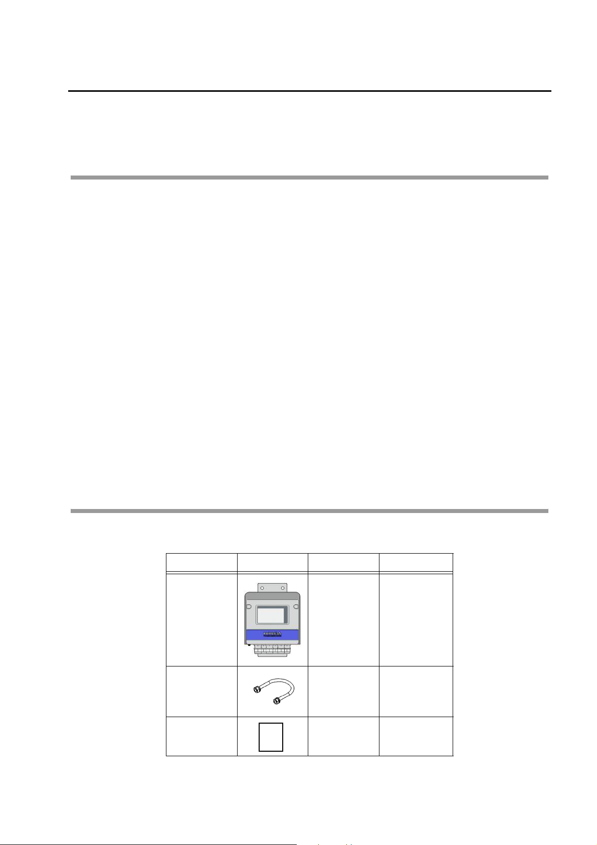
Q Items included
Name Illustration Quantity Remarks
Main body 1 set
U-bolt 2 sets
Instruction
manual
Instruction
manual
1 copy This document
With bracket
With cover
U-bolt: 2
M8 nut: 4
Spring washer:4
Flat washer: 4
1
Overview
Description of each part
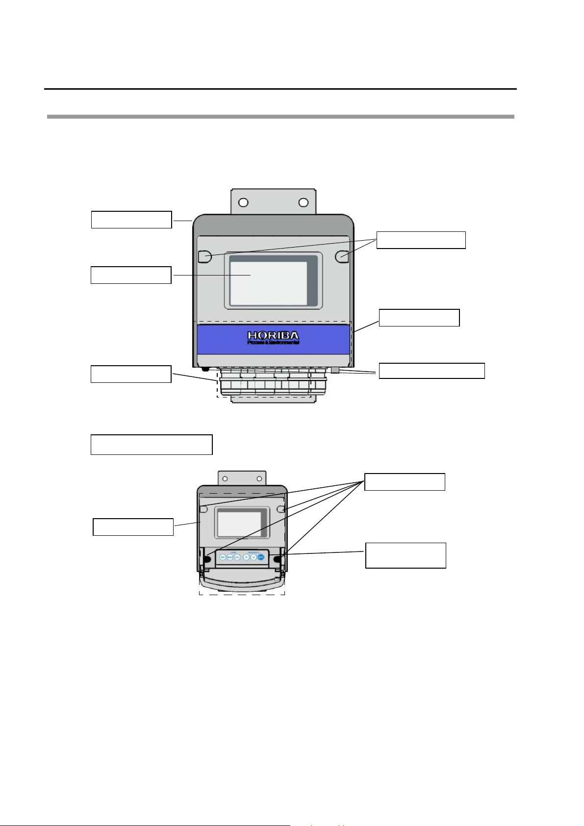
Q Front view
Cover
This cover is used for
outdoor installation.
Display part
The measured value
and other information
are displayed here.
Screw cap
When the two screw
caps are removed, the
front case screws
appear.
Front cover
When the cover is
opened, 6 operation
keys appear.
Conduit
Up to 6 electric wires
of 9 mm to 11.5 mm
diameter can be
used.
With the front cover opened
Front case
Purge air inlet
Purge air is sent
through this inlet to
prevent internal
corrosion. Normally
no connection is
required.
Front case screw
When the four screws
are removed, the front
case can be opened.
Operation key
section
6 operation keys are
located.
2
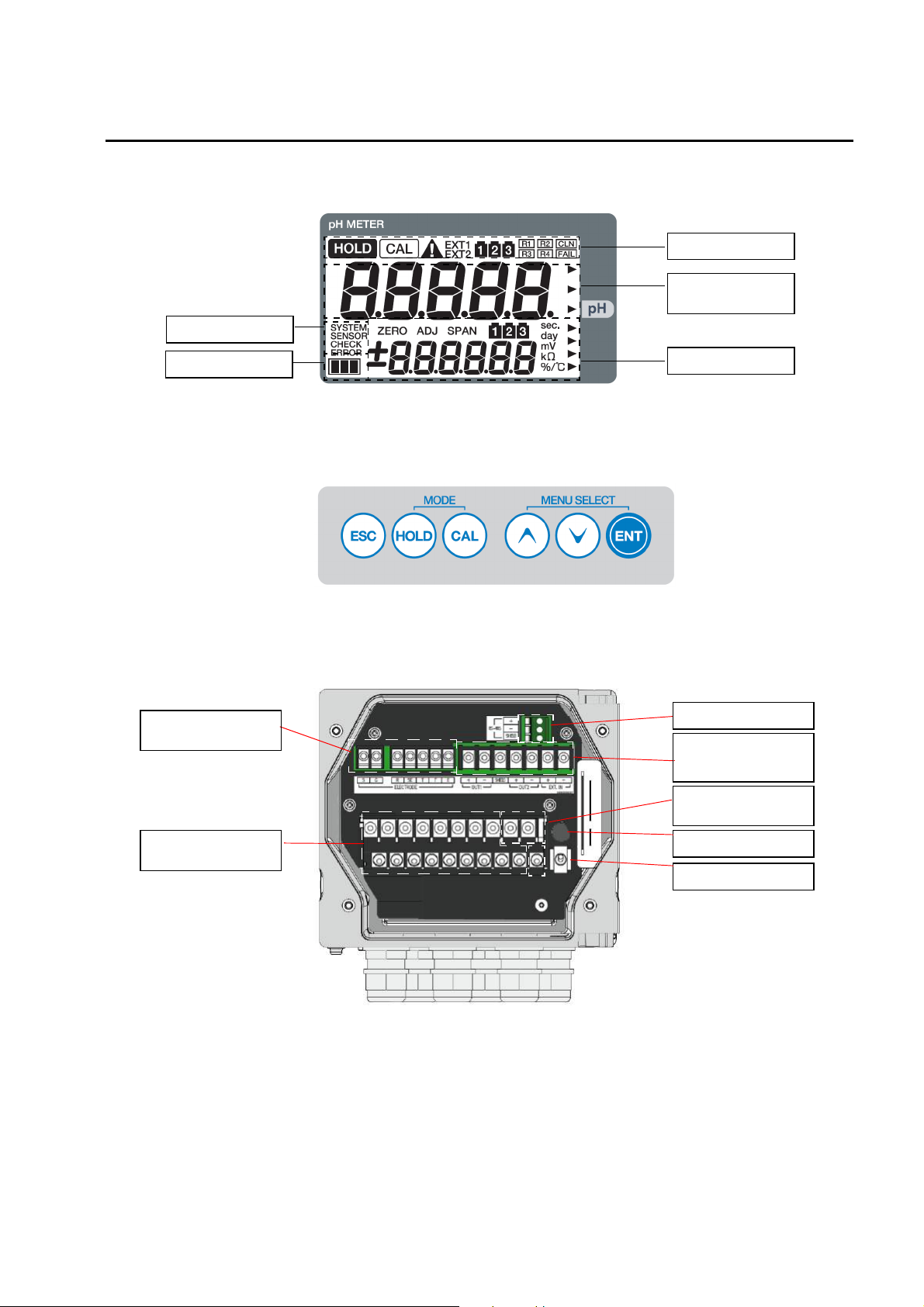
Q Display part
Status display
Overview
Status display
Measured value
display
Indicator
Q Operation key section
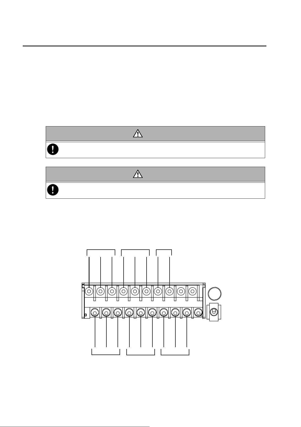
Q Terminal block
Electrode connection
terminal
Auxiliary display
RS-485 terminal
Transmission output
terminal and contact
input terminal
Power connection
terminal
Contact output
terminal
Fuse box
Power switch
3
Overview
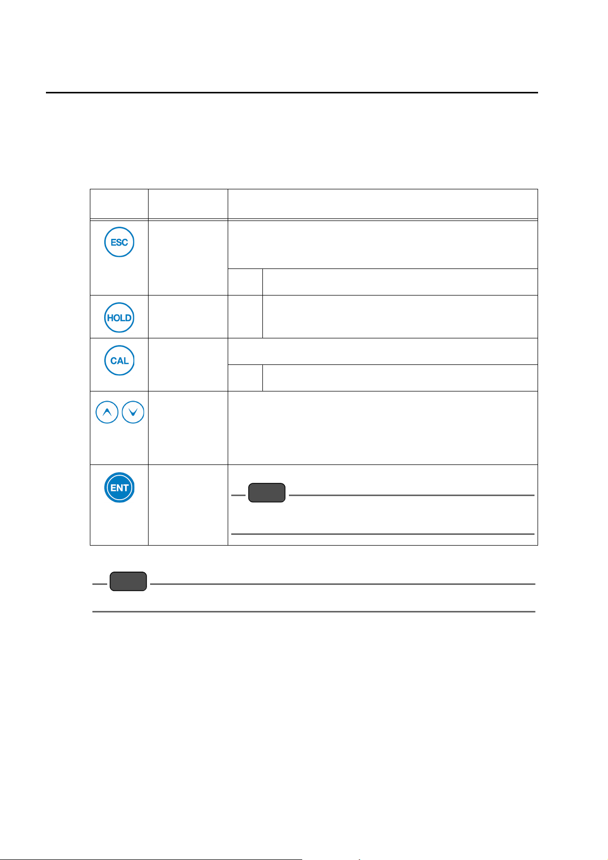
J Description of operation keys
The operation keys are used to change the displayed information, enter parameters, or
perform calibration.
The displayed value or item can be changed when it blinks.
Select a blinking value or item with the
setting will flash, indicating that it has been established.
S and T keys and then press the ENT key. The
Key
Nomenclature
(meaning) in text
ESC key (escape)
HOLD key (hold)
CAL key
(calibration)
[S] key
[T] key
(select)
Description
Used to go back to the previous menu from any other menu.
During various settings in the Hold mode, pressing this key will go back to
the previous item.
The change that has been previously made to any setting is canceled.
Hold
down
Hold
down
Allows you to change the number of calibration points or perform
calibration again during the basic calibration in the pH cal mode.
Hold
down
Used to change the displayed item or value.
Pressing the key will increase/decrease the value by an increment/
decrement of 1. Holding down the key will continuously increase/decrease
the value.
The
excessively scroll up or down with either key, press the other key to return.
Used to establish each setting or calibrated value.
Holding down this key in the Hold mode will select the Meas mode.
Holding down this key in the Meas mode will select the Hold mode.
Holding down this key in the Hold mode will select the Meas mode.
Holding down this key until the CAL indicator turns ON will select
the pH cal mode.
S and T key are used to scroll up and down, respectively. If you
ENT key (input)
No change is reflected if you have returned to the previous menu by
pressing the ESC key.
Note
Do not press any operation key with the tip of your nail or any pointed thing.
Note
4
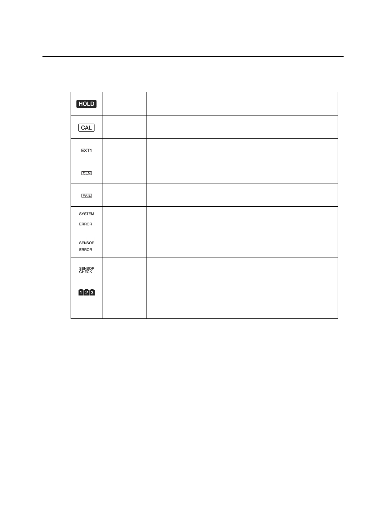
J Description of indicator
Q Status display
HOLD indicator
CAL indicator Turns ON when the cal mode becomes active.
EXT1 indicator Turns ON when contact input such as the cleaning signal is received
CLN indicator Turns ON when the cleaning output contact signal is output
FAIL Indicator Turns ON when the FAIL contact signal is output
SYSTEM
ERROR
indicator
Turn ON when system error E-90, E-91, or E-92 occurs
Overview
z Turns ON when the hold mode becomes active.
z Starts blinking when contact input is received or when the hold mode
becomes active due to an error
SENSOR
ERROR
indicator
SENSOR
CHECK
Bottle indicator
Turns ON when one of sensor errors E-11 to E-72 occurs
Illuminated during the check of the temperature sensor type when the
temperature sensor type was set to Auto
Illuminated during pH calibration
z Upper bottle indicator: The number of calibration points is indicated by
bottle indicator number.
z Middle bottle indicator: The current calibration point is indicated by bottle
indicator number.
5

Overview
Description of operation modes and menu items
The HP-200 offers 3 kinds of operation modes and 4 kinds of menus.
Q Operation mode
<Meas mode>
In this mode, measurements and control are performed.
<Cal mode>
In this mode, calibration is performed.
The cal mode is divided into the pH cal mode, the temp cal mode, and the pH manual input cal
mode.
<Hold mode>
In this mode, the measurement and output are stopped to make various settings.
Q Menu
The meas and hold modes have the respective menus as shown below:
For selecting each mode or item, see the corresponding paragraph.
<Meas mode>
<Cal/controlled value menu>
This menu allows you to check the calibrated value or to set/change some controlled values
while checking the output.
<Hold mode>
<Setup menu > (SET)
Prior to operation, this menu allows you to set all the measurement-related parameters such
as the input of detector information and the allocation of output.
<Cal menu> (CAL)
This menu allows you to select the cal mode.
<User Check menu> (USr)
This menu allows you to check the output status, the measured value, and others. The set
values can be reset to the factory settings.
6
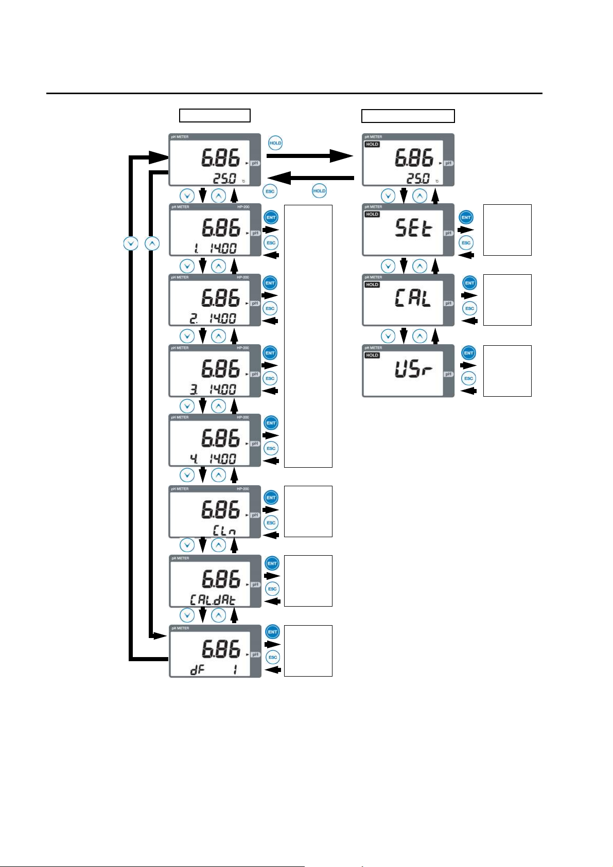
Q Modes and menus avaialble from meas mode
<Meas mode>
Hold down the
<Hold mode>
HOLD key
[T] key
The measurement output is held.
<Setup menu>
Overview
See P. 30.
Hold down the
CAL key.
Press the [S/T] key.
[T] key
[T] key
<pH cal mode>
(ph calibration)
<Cal/controlled value menu>
<Cal menu>
(ph/temperature
calibration)
<User Check menu>
See P. 39.
See P. 44.
See P. 47.
See P. 26.
7
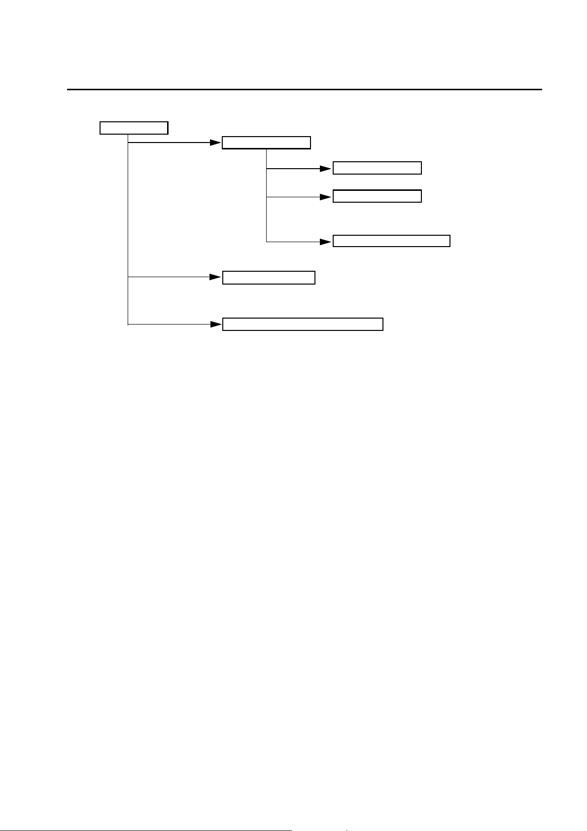
Overview
<Meas mode>
(Hold down)
or
Check
contact
output
(Hold down)
<Hold mode>
Setup
menu
Cal
menu
User
Check
menu
Check
cleaning
Check the
calibrated
value
Check the
controlled
value
8

Installation
Installation environment
To ensure the use of the HP-200 in stable condition, install the HP-200 in a location where the
following requirements are met:
Q HP-200
z The location shall be well ventilated.
z The ambient temperature shall be between -20°C and 55°C both inclusive.
z Hot air in the location shall be minimal.
z The HP-200 shall not be exposed to direct sunlight.
z The HP-200 shall not be exposed to direct high radiation heat.
z The ambient relative humidity shall be 90% maximum.
z The HP-200 shall not be exposed to splashed water or chemical agent
z The mechanical vibration in the location shall be minimal.
z Maintenance and wire connections shall be possible in the location.
z The location shall be free from dust and corrosive gas.
z The location shall be least affected by an electromagnetic field.
z The altitude shall be 2,000 meters max.
z The variation range of power supply voltage shall fall within ±10%.
Installation
Q Electrode
z The location shall enable the check and maintenance of the electrode.
z The solution under measurement shall be free from air bubbles.
z The solution under measurement shall not corrode the wetted part of the electrode.
Note
z For more information, refer to the instruction manual that comes with the electrode.
z To measure any solution that has high SS content, the installation of a cleaner is recommended.
9
Installation
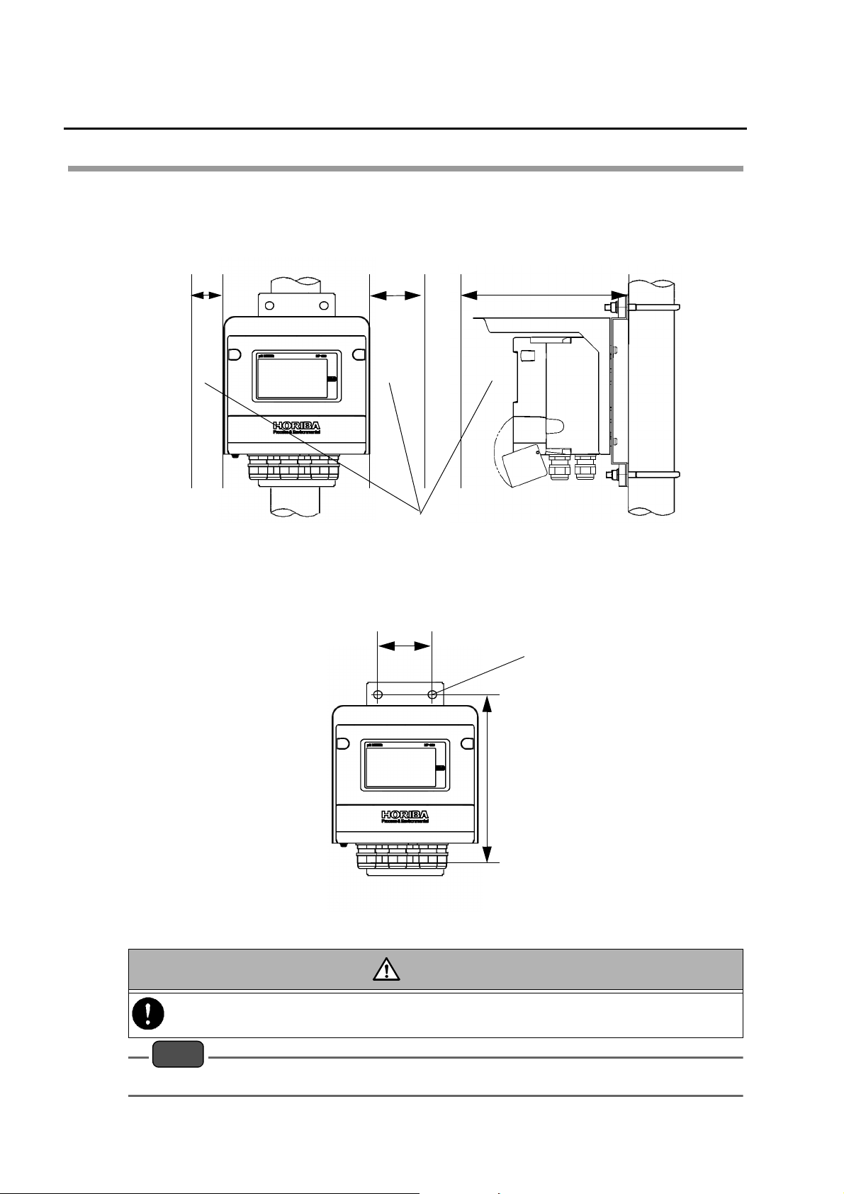
Installing the HP-200
The HP-200 can be installed on a pole (50A) or a wall.
Q Installation on a pole
View of the HP-200 installed on a pole
12050
262
Q Installation on a wall
View of the HP-200 installed on a wall
Maintenance
area
71
[Unit: mm]
Slotted hole of 4-10 x 11
220
[Unit: mm]
10
CAUTION
If there is any corrosive gas in the installation environment, send clean instrumentation air through the
air purge inlet on the HP-200.
Note
Provide the necessary area for the maintenance of the HP-200.
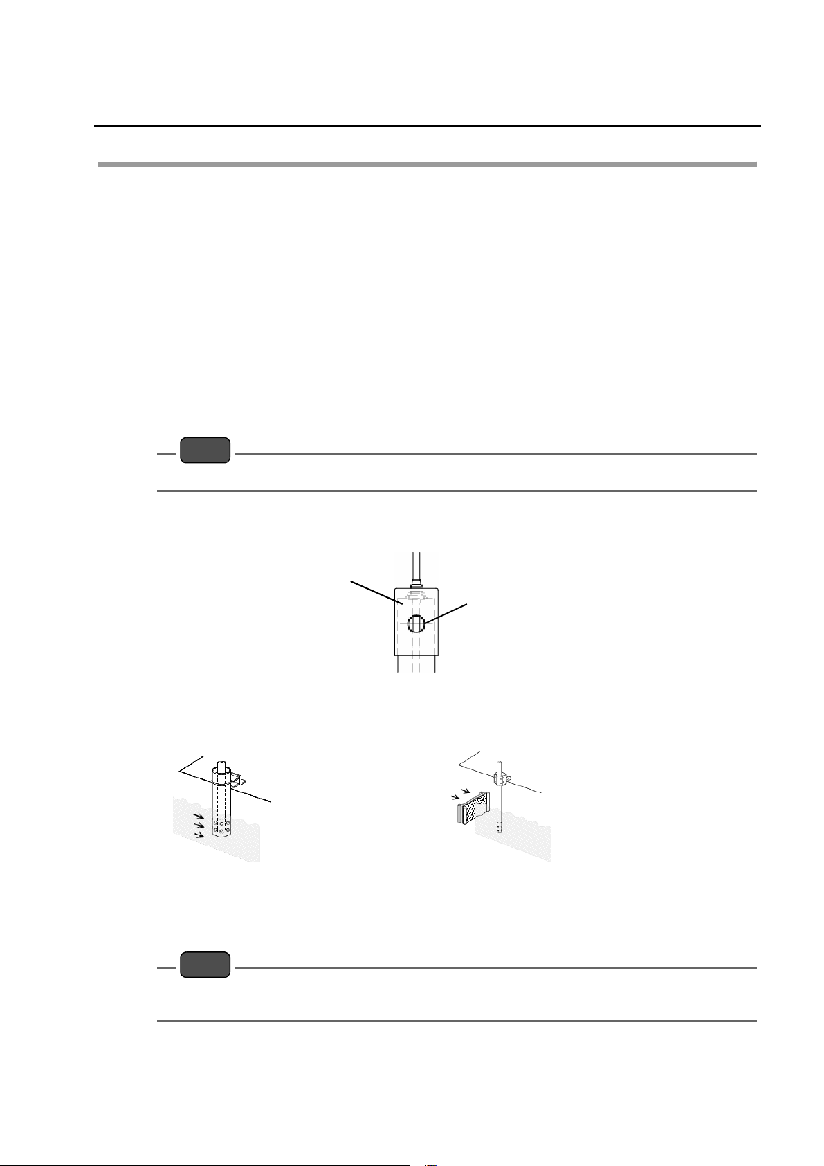
Installing the electrode
The electrode can be installed by either of the following two methods:
z Set up the electrode with a holder and then directly immerse the holder in the solution
under measurement (immersion type holder).
z Set up the electrode with a holder and then directly insert the holder into the piping line
(distribution type holder).
For detailed handling of each holder type, refer to the instruction manual that comes with the
product.
Q For immersion type holder
Ensure that the electrode tip is always immersed in the solution under
1.
measurement even if the solution level fluctuates.
2. Ensure that the level of the internal solution (KCl) in the holder is always higher
than the level of the solution under measurement.
Note
If the level of the internal solution (KCl) in the holder decreases, be sure to add the internal solution.
Installation
3. Slightly turn the cap at the top of the holder. The filling inlet will be slightly opened
so that large pressure is applied to the inside of the holder.
Holder cap
KCl filling inlet
4. The maximum flow rate is 2 m/s. Even if the flow rate is within this limit, the folder
may be deformed. Therefore, take the following measures to prevent a decrease in
the flow rate.
Install a pipe of 50 to 100
A that has a introducing
hole at its end and then
insert the holder into that
pipe.
When a partition plate
can be installed, e.g., on
both sides of a street
gutter, install those plates
upstream for the benefit
of dust removal.
Q For distribution type holder
Be sure to provide a bypass line on the piping line.
1.
Note
Unless there is a bypass line, the HP-200 must be stopped when the maintenance or replacement of
the electrode is carried out.
2. Use the distribution type holder with its output side open to atmospheric air.
3. Before checking the electrode, close the valve located upstream from the holder.
The solution in the holder may flow back.
11
Installation
4. An excessively high flow rate may cause fluctuations in the reading. An
excessively low flow rate results in response delay. Control the flow rate in
accordance with the measurement conditions.
5. For any solution under measurement that has large SS content, install a strainer on
the incoming side.
Procedures for connections
Q Opening the cover for the HP-200
Remove two screw caps located on the upper part of the front of the HP-200.
1.
Carefully store the removed caps.
2. Open the front cover.
3. Loosen four screws located on the front of the HP-200. Check that the screws are
floated by springs.
4. Open the front case for the HP-200.
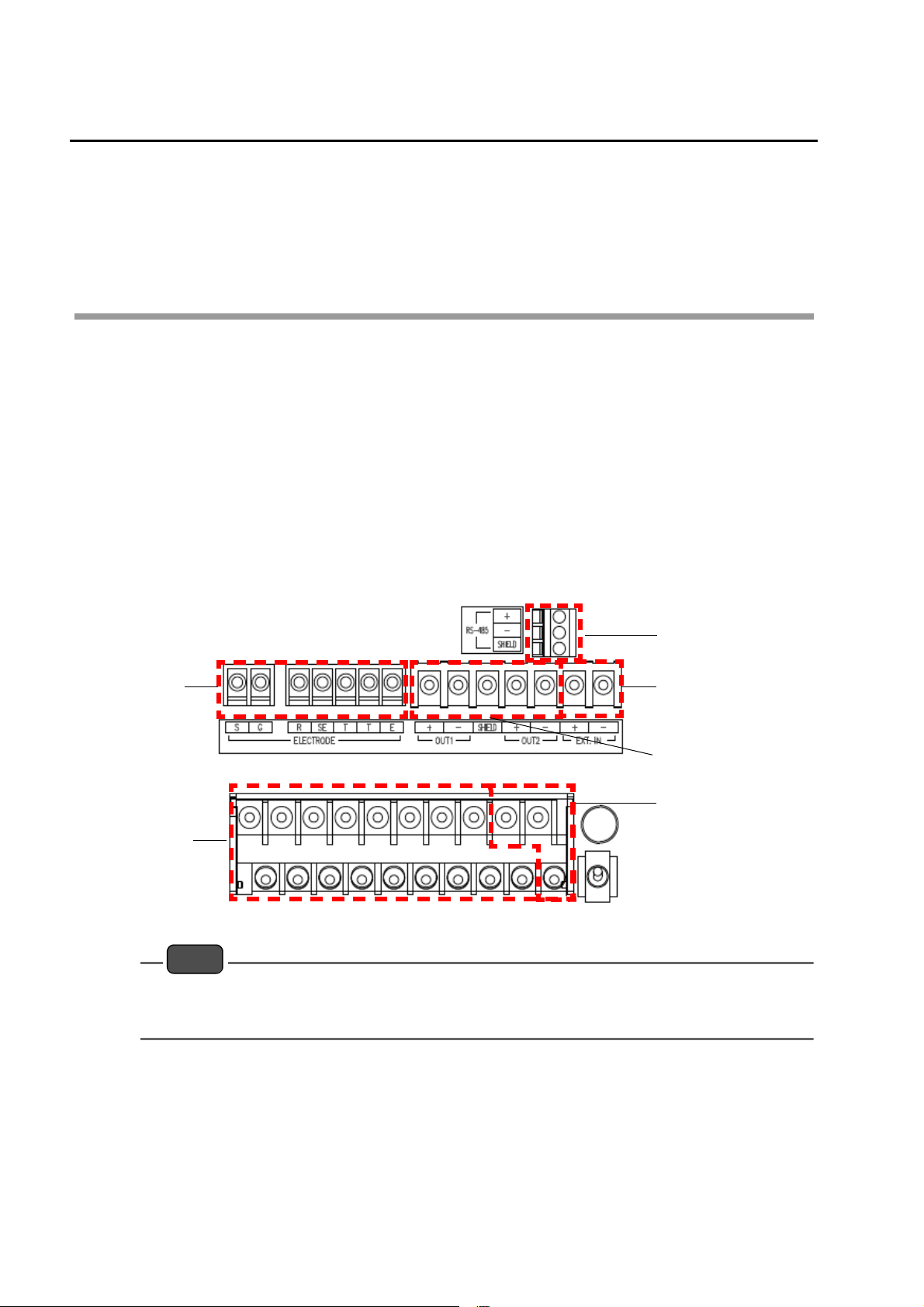
Q Diagram of connection terminals
Electrode
terminal
(M3)
Contact output
terminal (M4)
Note
z The screws on the front case and the terminal block are structurally prevented from coming off.
To connect a terminal, turn the screw counterclockwise until the spring is floated.
z To open the case immediate after it has rained, previously wipe off droplets on the case.
Communication
terminal
Contact input
terminal (M3.5)
Transmission
output terminal
(M3.5)
Power terminal
(M4)
12
J Connecting the power source
z The HP-200 has a power switch.
z For the HP-200, use a free power source for rated voltage of 100 to 240 VAC.
z The terminals crew for the contact output is of M4.
z The applicable electric wire is of 0.75 to 5.5 mm
z Provide the power switch in a place near the HP-200 so that the power can be turned ON/
OFF.
If lightning might strike, install an arrester on the output side of the HP-200 and on the side of
receiving instruments.
Electric shock hazard
Be sure to check that no power is supplied before starting work.
2
(AWG18 to 10).
WARNING
CAUTION
Installation
Operation outside the rated range can cause a fault. Therefore, check the power supply voltage. Also
check that fluctuations of the power supply voltage fall within ±10%.
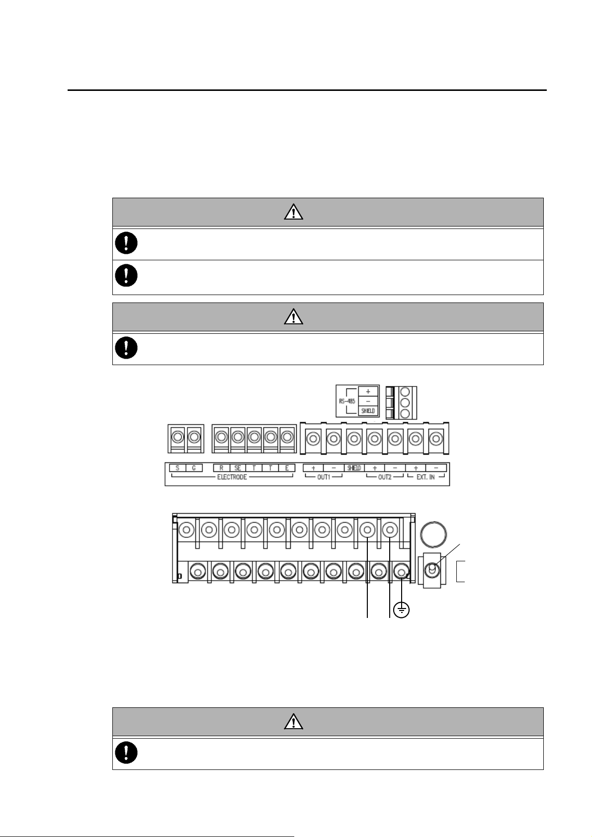
As illustrated below, connect the power cable and the grounding cable.
Class D grounding
(L) (N)
Power supplied
Voltage: 100 V to 240 VAC
Frequency: 50/60 Hz
Power switch
ON
OFF
Q Instructions for grounding
WARNING
Be sure to ground the grounding terminal (class D grounding).
Separate this grounding from any other grounding for electric equipment such as a motor.
13
Installation
J Connecting the contact output terminal
z The contact capacity is 250 VAC, 3 A maximum or 30 VDC, 3 A maximum for resistance
load.
z The terminal screw for the contact output is of M4.
z The applicable electric wire is of 0.75 mm
z If noise is detected from the load, use a varistor or a noise killer.
z Only the CLN output involves voltage from the connected power source. Others are no-
voltage contact output.
z For the FAIL output only, NO and NC are reversed.
When the HP-200 is normal (not in failure), the CF-NOF contact is open and the CF-NCF
contact is short-circuited. When the power is OFF, the C-NOF contact is short-circuited.
To connect any load exceeding the contact capacity or any induction load (e.g., a motor or a pump),
be sure to use a power relay exceeding the load rating.
2
to 5.5 mm2 (AWG18 to 10).
WARNING
When the HP-200 is OFF, the C-NC contact for R1 to R4 is short-circuited. Therefore, be careful
about the connection of load.
As illustrated below, connect the contact output:
R3
(control output)
C3
NC3
R4
(control output)
NC4
NO3
C4
NO4
CAUTION
CLN (cleaning output)
* output with voltage
OUT (L)
OUT (N)
14
C1
NC1
R1
(control output)
NO1
C2
NC2
R2
(control output)
NO2
CF
NOF
FAIL
(error warning output)
NCF
Installation
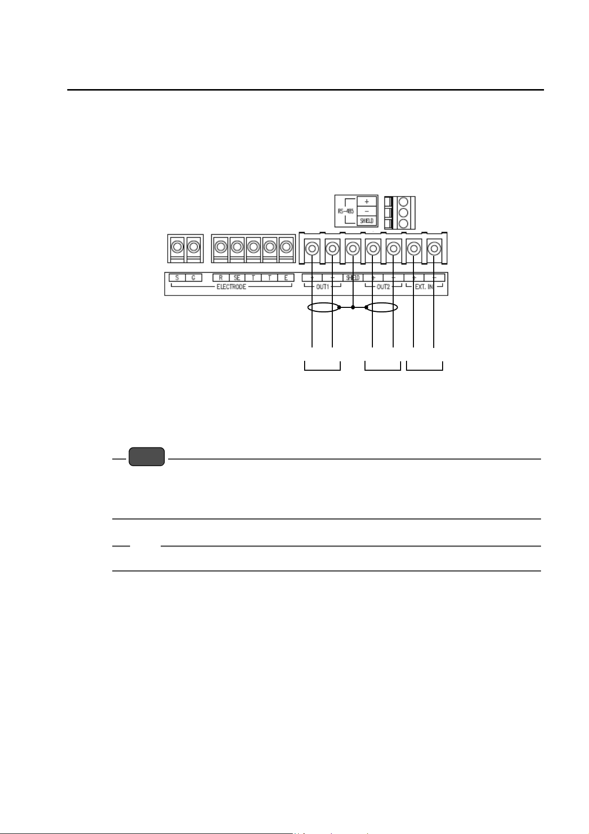
J Connecting the contact input terminal and the transmission output terminal
z The terminal screws for the contact input and the transmission output are of M3.5.
z The applicable electric wire is of 2 mm
z For the transmission output cable, use a shielded cable.
z When lightning might strike, install an arrestor on the output side of the HP-200 and on
the side of receiving instruments.
2
(AWG14) maximum.
(+) (-) (+) (-)
OUT1 OUT2
(transmission output)
(+) (-)
EXT.IN
(contact
input)
Note
z The resistor for the contact input shall be 100Ω maximum.
z The maximum load resistance for the transmission output is 900Ω.
z The negative terminal (OUT1) (−) and OUT2 (−) for the transmission output are internally
connected and have the same electric potential.
Tip
When the contact input is turned ON, the EXT1 indicator on the display part is illuminated.
15
Installation
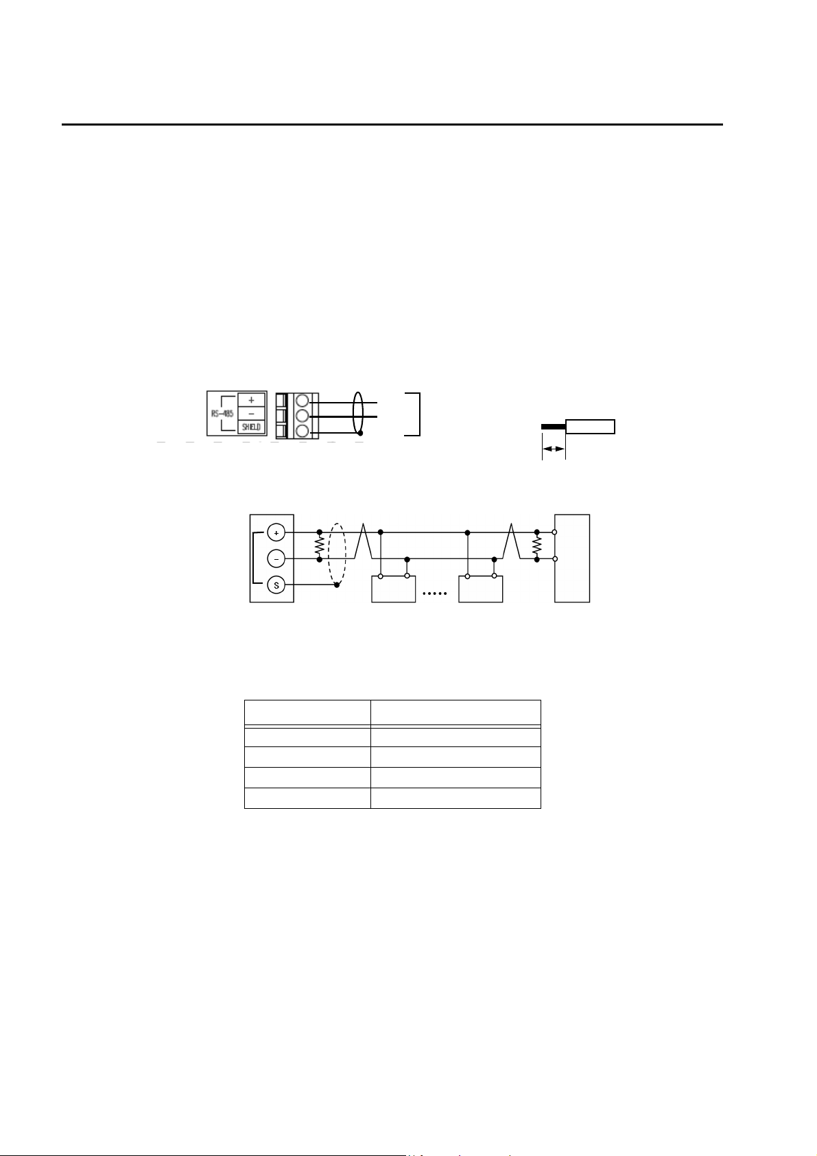
J Connecting the communication terminal
Q Connecting the RS-485 terminal
The HP-200 has an RS-485 communication terminal. To use this terminal, connect wiring.
z The applicable electric wire is of 0.14 mm
z For the communication output cable, use a twisted shielded pair.
z Up to 32 connections can be made including one for the host computer. For address
settings, see “ Set RS-485 address ” (page 38).
z The communication cable length is 500 m maximum.
z To terminate the cable, strip the covering at the end by 11 mm and then connect the
stripped end to the terminal.
z Use a terminating resistor (Rt: 120 Ω) for any device at which the RS-485 communication
line is terminated.
2
to 2.5 mm2 (AWG26 to 14).
(+)
(-)
Example of external connection for communication
HP-200
RS-485
(communication
output)
Rt Rt
Q RS-485 communication conditions
The RS-485 communication conditions are shown below:
Item Condition
Baud rate 19200 bps
Character length 8 bit
Parity None
Stop bit 1 bit
RS-485
(communication
output)
Terminal treatment for
cable
11 m m
Host computer
16
J Connecting the electrode cable
Q Cautionary instructions for electrode cable
The pH electrode cable is highly insulated. In handling this cable, pay attention to the following
points:
z Do not wet any cable terminal or the terminal block with water or the like; also do not soil
it with dirt, oil, or the like. The insulation will otherwise deteriorate.
The decreased insulation can cause instable readings. Maintain the electrode cable in a
dry, clean state.
If the electrode cable should be soiled, wipe it off with alcohol or the like and then well dry it.
z In routing the electrode cable, provide sufficient length for the calibration of standard
solution and the check and replacement of the electrode.
z Route the electrode cable and the relay cable by avoiding any place near inducing
equipment such as a motor and keeping them away from the power cable for such
equipment.
Q Connections
The electrode cable has the following terminals:
S:
G: Glass electrode terminal
R: Comparison electrode terminal
SE: Wetted pole terminal
T, T:
E: Shielded terminal
Glass electrode shielded drive
terminal
Temperature compensation
electrode terminal
Installation
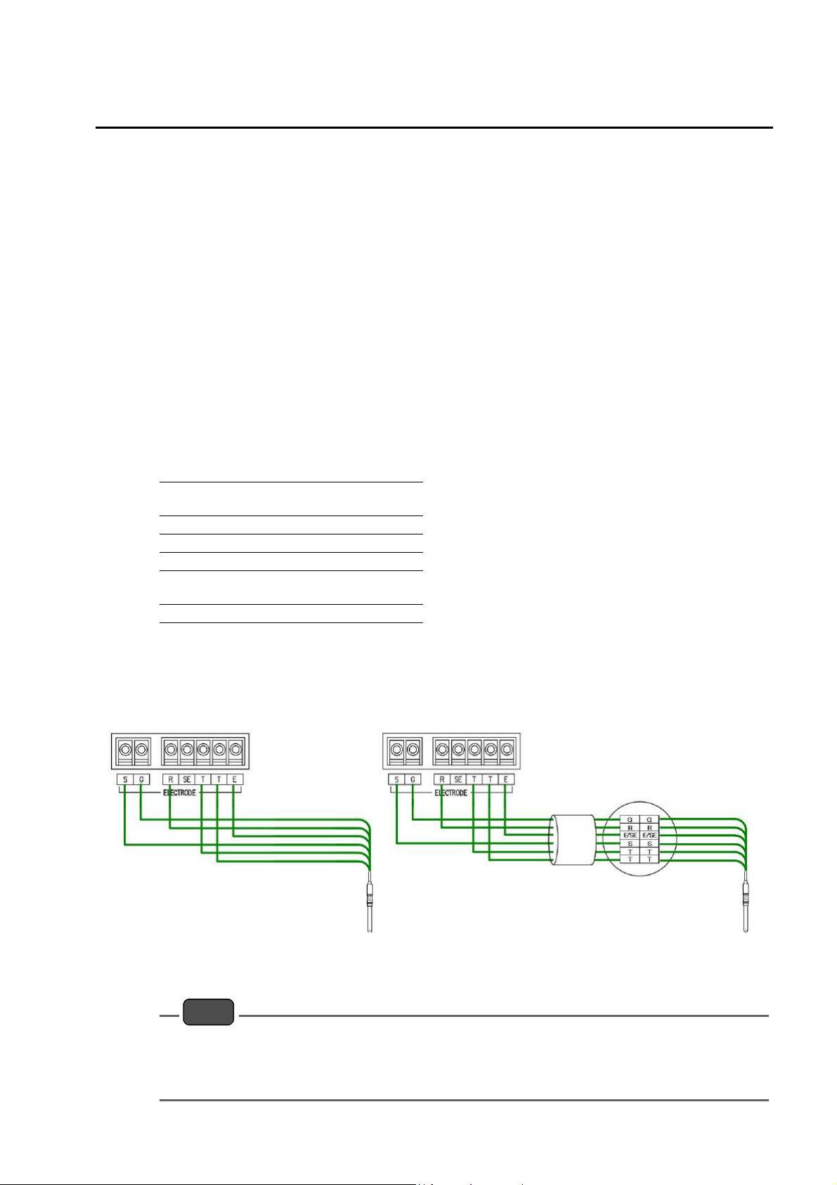
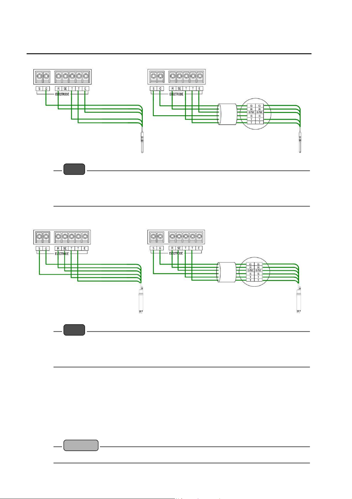
As illustrated below, connect the terminals of the electrode cable to the corresponding
terminals on the terminal block.
z For pH electrodes with S terminal and without SE terminal, such as 6108 and 6109
Terminal block Terminal block
Relay cable
(C-5A-YT2-PS)
pH electrode
(6108 and 6109)
Relay box
(CT-25pH)
pH electrode
(6108 and 6109)
Note
For the above electrode
z Be sure to select "cLoSE" in “ Set R-SE connection ” (page 32) on the Setup menu.
z Be sure to select "g" or "non" in “ Set sensor self-check ” (page 32) on the Setup menu. For this
electrode having no wetted pole, a liquid junction resistance error cannot be detected.
17
Installation
z For pH electrodes without S and SE terminals, such as 6110
Terminal block Terminal block
Relay cable
(C-5A-YT2-PS)
pH electrode
(6110)
Relay box
(CT-25pH)
pH electrode
(6110)
Note
For the above electrode
z Be sure to select "cLoSE" in “ Set R-SE connection ” (page 32) on the Setup menu.
z Be sure to select "g" or "non" in “ Set sensor self-check ” (page 32) on the Setup menu. For this
electrode having no wetted pole, a liquid junction resistance error cannot be detected.
z For pH electrodes with S and SE terminals, such as 6171, 6172, 6173, and 6174
Terminal block Terminal block
Relay cable
(C-5A-YT2-PS)
Relay box
(CT-25pH)
pH electrode
(617X)
pH electrode
(617X)
Note
For the above electrode
z Select "oPEn" in “ Set R-SE connection ” (page 32) on the Setup menu.
z A liquid junction resistance error can be detected by selecting "gr" in“ Set sensor self-check ”
(page 32) on the Setup menu.
Q Temperature compensation electrode
For the HP-200. one of the following four kinds of temperature compensation electrodes can
be used:
Resistance value at 25°C: 500 Ω, 680 kΩ, and 10 kΩ
Resistance value at 0°C: 1 kΩ
Check the resistance-temperature detector type for the electrode used and accordingly set the
temperature compensation for the HP-200 to an appropriate value.
Reference
“ Setup menu ” (page 30)
18
Q Extending the electrode cable
To extend the electrode cable, be sure to use:
z our extension cable (C-5A-YT2-PS or C-5A-YT2-PSE) exclusively for the electrode cable; and
z our relay box (CT-25pH) for exclusive use.
The electrode cable is extendable up to 50 meters between the HP-200 and the electrode.
It is recommended that the dedicated relay cable be housed in a conduit pipe to prevent static
electricity from being generated due to induction, vibration, or any other reason. In this case,
pass the wiring near the HP-200 through a flexible tube.
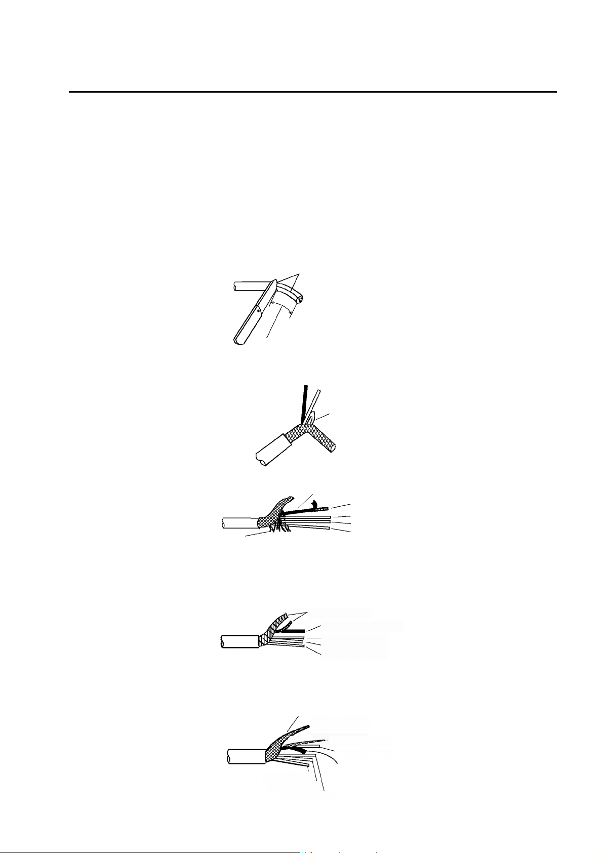
Procedure for terminal treatment of C-5A cable
Perform the following steps to complete the terminal treatment:
1. Strip covering of the cable.
Remove the covering cut with a
knife.
About 12 cm required for connection
Installation
2. Break the braided shield somewhere in a place near the remaining covering and
then take out the lead wires.
Take out
the lead
wires.
3. Completely remove lint from the inside of the shield.
Lead wire: Black
Braided shield
Lead wire: Red
Lead wire: White
Lint
Lead wire: Blue
4. Strip covering of the lead wire (black) up to a place near the remaining covering of
the electrode cable and then take out the braided shield for that lead wire.
5. Take out the black lead wire with a white line from the braided shield for the lead
wire (black).
Braided shield
Lead wire: Black with a
white line
Lead wire: Red
Lead wire: White
Lead wire: Blue
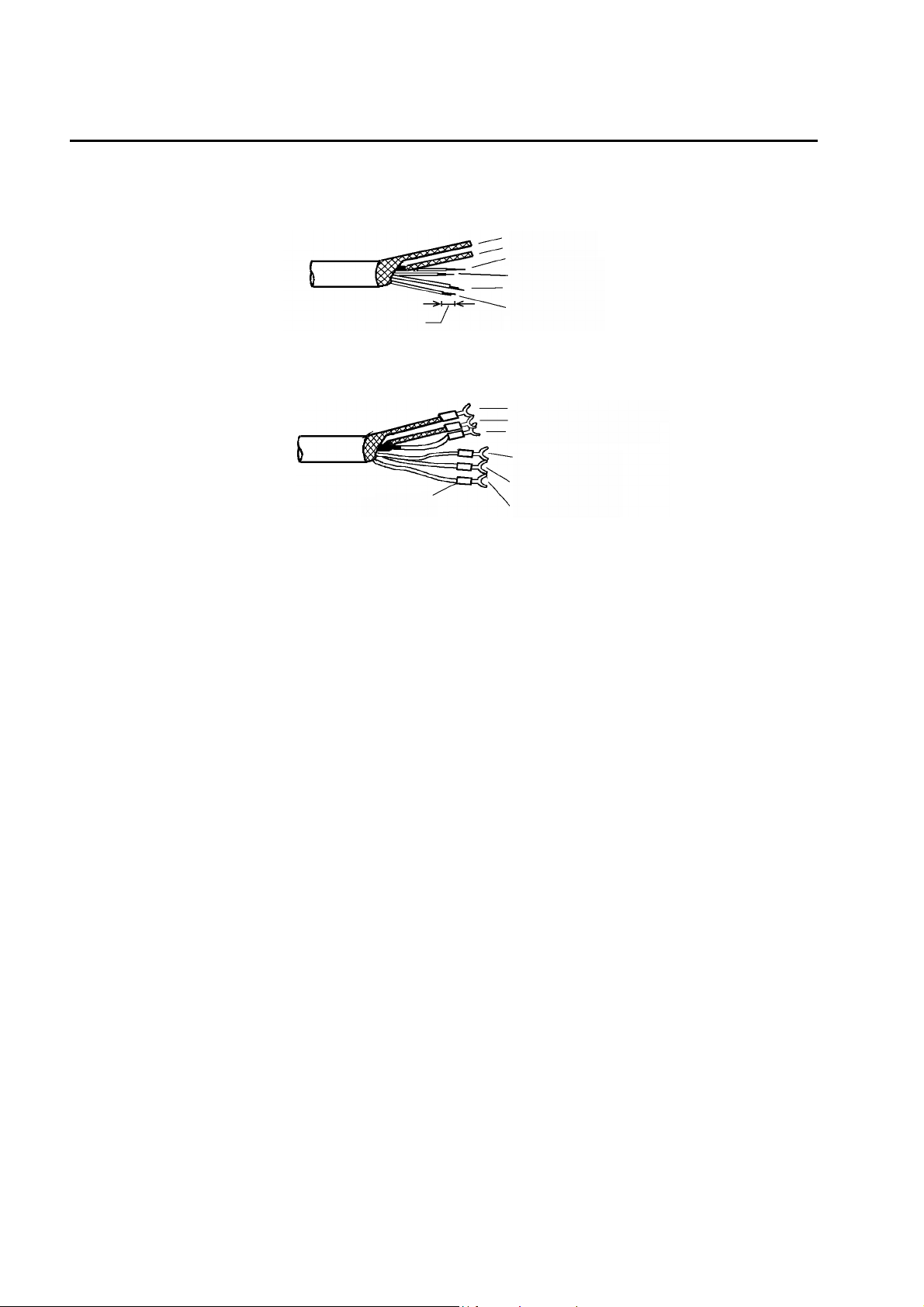
6. Strip covering of the lead wire (black with a white line).
Be sure to strip covering (conductive plastic: black with a white line) up to the root of the
transparent lead wire.
Extend to make the braided shield thinner
Braided shield 1
Braided shield 2
Lead wire: transparent
Lead wire: Blue
Lead wire: White
Lead wire: Red
Strip up to the root
19
Installation
7. Strip each of the lead wires so that its copper wire end is exposed about 1 cm.
In stripping the covering of a conductive wire, take care not to cut the conductive wire.
Cover each of braided shields 1 and 2 with a shrinking tube to avoid short-circuit.
Braided shield 1
Braided shield 2
Lead wire: Transparent
Lead wire: Red
Lead wire: White
Strip about 1 cm to expose a conductive wire
Lead wire: Blue
8. Attach a crimp-type terminal to the conductive wire and then properly crimp it with
a crimp tool.
Braided shield 1: To SE terminal
Braided shield 2: To S terminal
Transparent: To G terminal
White: To R terminal
Red: To T terminal
Crimp-type terminal
Blue: To T terminal
9. Pull the terminal to check that it is properly crimped.
20
Operation
Preparation for operation
When first using the HP-200 after it has been shipped from factory or reset to the factory
settings, perform the following work:
z Checking the wiring
z Initial setup
z Calibration
Q Checking the wiring
Check the following points:
z The power cable (transmission cable) and the electrode cable are connected properly.
z The terminal block screws are free from loosening.
z The voltage fluctuations fall within the range from 100 V to 240 VAC ±10%.
Operation
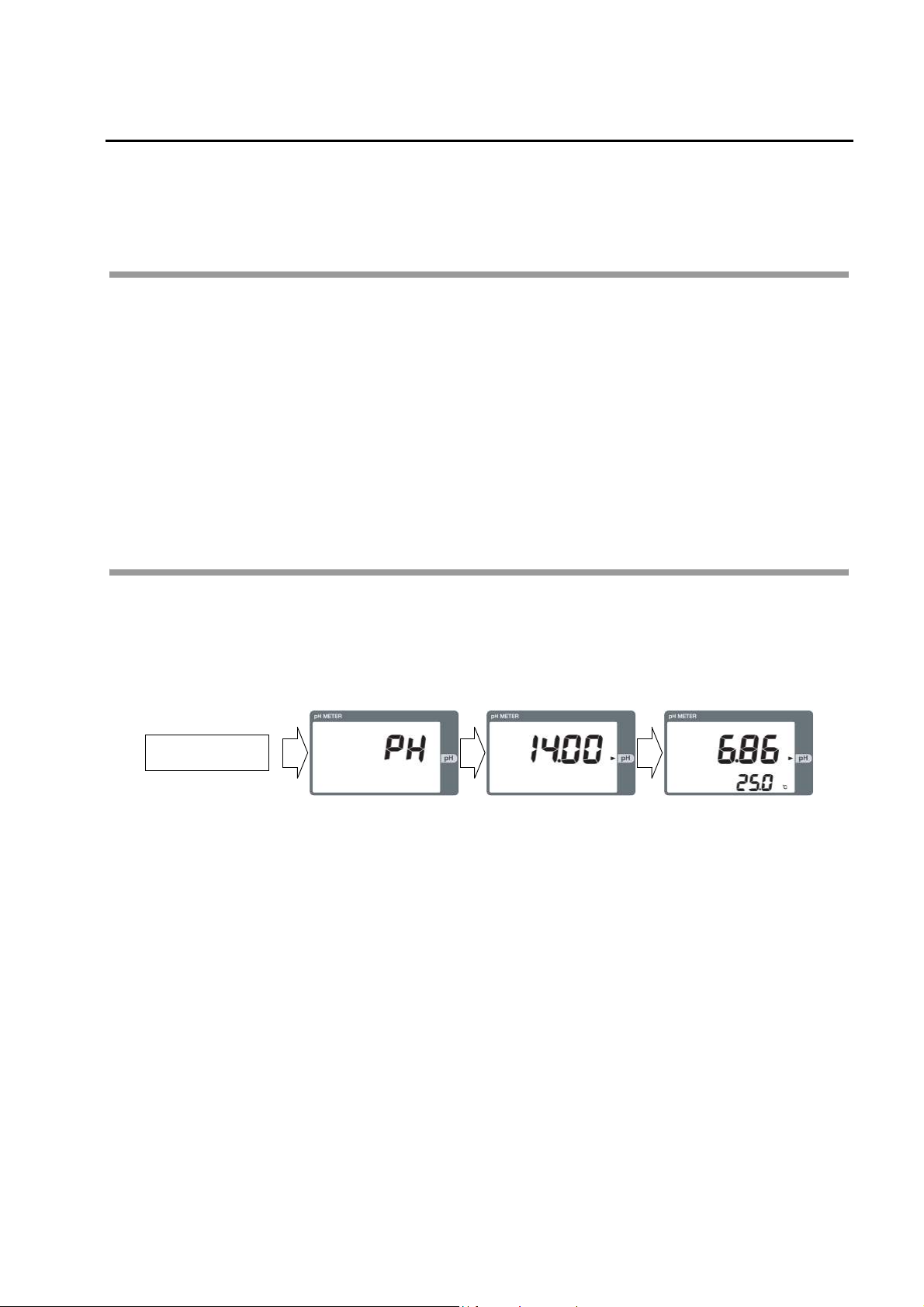
Starting operation
Q Turning ON the power
When the power is turned ON, the initial screen will be displayed with the meas mode
selected.
Power ON
Displayed for a few
seconds
<Meas mode>
21
 Loading...