

horiba FluoroMax-3, FluoroMax-P Operation Manual
FluoroMax-3 v. 3.1 (3 Mar 2006)
FluoroMax®-3 & FluoroMax®-P
with FluorEssence™
Operation Manual
http://www.jobinyvon.com
Rev. 3.1
USA:
Tel: +1-732-494-8660, Fax: +1-732-549-5125, E-mail: info@jobinyvon.com, www.jobinyvon.com
France:
Tel: +33 (0) 1 64 54 13 00
Japan:
Chiyoda-ku, Tokyo 101-0031, Tel: +81 (0) 3 3861 8231, www.jyhoriba.jp
Germany:
(All HORIBA Jobin Yvon companies were formerly known as Jobin Yvon)
China:
HORIBA Jobin Yvon Inc., 3880 Park Avenue, Edison, NJ 08820-3012, Toll-Free:
HORIBA Jobin Yvon S.A.S., 16-18, rue du Canal, 91165 Longjumeau Cedex,
HORIBA Ltd., JY Optical Sales Dept, Higashi-Kanda, Daiji Building, 1-7-8 Higashi-Kanda
+49 (0) 89 462317-0
+86 (0) 10 6849 2216
,
Fax: +33 (0) 1 69 09 93 19, www.jobinyvon.fr
Italy:
+39 0 2 57603050
UK:
+44 (0) 20 8204 8142
+1-866-jobinyvon
i

FluoroMax-3 v. 3.1 (3 Mar 2006)
Copyright © 2001–2006 by HORIBA Jobin Yvon
Inc.
All rights reserved. No part of this work may be
reproduced, stored, in a retrieval system, or
transmitted in any form by any means, including
electronic or mechanical, photocopying and
recording, without prior written permission from
HORIBA Jobin Yvon Inc. Requests for permission
should be requested in writing. Origin® is a registered
trademark of OriginLab Corporation. Alconox® is a
registered trademark of Alconox, Inc. Ludox® is a
registered trademark of W.R. Grace and Co. Teflon®
is a registered trademark of E.I. du Pont de Nemours
and Company.
Part Number 81038
Information in this manual is subject to change
without notice, and does not represent a commitment
on the part of the vendor.
April 2006
ii

FluoroMax-3 v. 3.1 (3 Mar 2006)
Table of Contents
0: Introduction ................................................................................................0-1
About the FluoroMax®-3 and FluoroMax®-P........................................................................................... 0-1
Chapter overview....................................................................................................................................0-2
Disclaimer...............................................................................................................................................0-3
Safety summary......................................................................................................................................0-5
Risks of ultraviolet exposure...................................................................................................................0-7
Additional risks of xenon lamps............................................................................................................0-10
1: Requirements & Installation ............................................................................1-1
Safety-training requirements ..................................................................................................................1-1
Surface requirements.............................................................................................................................1-2
Environmental requirements...................................................................................................................1-3
Electrical requirements...........................................................................................................................1-4
Unpacking and Installation .....................................................................................................................1-5
Software emulation.................................................................................................................................1-9
2: System Description....................................................................................... 2-1
Introduction.............................................................................................................................................2-1
Basic theory of operation........................................................................................................................2-1
Optical layout..........................................................................................................................................2-2
3: System Operation......................................................................................... 3-1
Introduction.............................................................................................................................................3-1
Controls and indicators...........................................................................................................................3-1
Turning on the system............................................................................................................................3-2
Checking system performance...............................................................................................................3-3
4: Data Acquisition........................................................................................... 4-1
Experiment Menu button ........................................................................................................................4-2
Previous Experiment Setup button.........................................................................................................4-4
Auto Run Previous Experiment button ...................................................................................................4-5
Make Overlay File button........................................................................................................................4-6
3D Scan to 3D Profile button..................................................................................................................4-7
Get Peak Information button...................................................................................................................4-9
Running an unknown sample...............................................................................................................4-10
5: Optimizing Data ........................................................................................... 5-1
Cuvette preparation................................................................................................................................5-1
Sample preparation ................................................................................................................................5-2
Running a scan on a sample..................................................................................................................5-4
Measuring the G factor...........................................................................................................................5-6
Improving the signal-to-noise ratio .........................................................................................................5-8
Correcting data.....................................................................................................................................5-14
6: Maintenance...............................................................................................6-1
Introduction.............................................................................................................................................6-1
Lamp replacement..................................................................................................................................6-1
Electronics..............................................................................................................................................6-9
7: Troubleshooting...........................................................................................7-1
Chart.......................................................................................................................................................7-1
Checking the FluoroMax
Using diagnostic spectra ........................................................................................................................7-5
Further assistance… ............................................................................................................................7-10
®
’s BIOS...........................................................................................................7-3
iii

FluoroMax-3 v. 3.1 (3 Mar 2006)
8: Producing Correction Factors ........................................................................... 8-1
Introduction.............................................................................................................................................8-1
Generating emission correction factors..................................................................................................8-2
Calculating emission correction factors..................................................................................................8-3
Calculating excitation correction factors.................................................................................................8-5
Using correction-factor files..................................................................................................................8-10
9: FluoroMax®-P Phosphorimeter Operation ............................................................ 9-1
Introduction.............................................................................................................................................9-1
Theory of operation ................................................................................................................................9-2
Applications for the phosphorimeter.......................................................................................................9-5
Operation of the phosphorimeter............................................................................................................9-8
Processing phosphorimeter data..........................................................................................................9-10
Lamp replacement................................................................................................................................9-11
10: Automated Polarizers..................................................................................10-1
Introduction...........................................................................................................................................10-1
Installation.............................................................................................................................................10-5
Alignment..............................................................................................................................................10-6
Using automated polarizers................................................................................................................10-14
Maintenance.......................................................................................................................................10-19
Troubleshooting..................................................................................................................................10-20
11: Technical Specifications ..............................................................................11-1
Spectrofluorometer system...................................................................................................................11-2
Minimum computer requirements.........................................................................................................11-4
Software................................................................................................................................................11-4
12: Components & Accessories...........................................................................12-1
Itemized list of FluoroMax®-3 accessories ...........................................................................................12-2
Model 1940 Absorption/Transmission Accessory................................................................................ 12-3
FL-1013 Liquid Nitrogen Dewar Assembly...........................................................................................12-6
Model 1908MOD Scatter Block Assembly ...........................................................................................12-7
Model 1908 Standard Lamp Assembly ................................................................................................12-7
Sample cells .........................................................................................................................................12-8
F-3000 Fiber Optic Mount.....................................................................................................................12-9
Model 1938 Cut-On Filter...................................................................................................................12-10
Model 1939 Cut-On Filter...................................................................................................................12-10
FL-1010 Cut-On Filter Holder.............................................................................................................12-11
FL-1011 Four-Position Thermostatted Cell Holder ............................................................................ 12-12
FL-1012 Dual-Position Thermostatted Cell Holder ............................................................................ 12-14
Model 1933 Solid Sample Holder.......................................................................................................12-16
F-3005/6 Autotitration Injector............................................................................................................12-18
Microscope Interface..........................................................................................................................12-19
Model 1905-OFR 150-W Xenon Lamp...............................................................................................12-20
F-3004 Sample Heater/Cooler Peltier Thermocouple Drive ..............................................................12-21
FM-2005 Phosphorimeter upgrade ....................................................................................................12-22
MicroMax 384 Microwell Plate Reader...............................................................................................12-23
Fl-1044 L-Format Polarizer.................................................................................................................12-24
FL-1015 Injector Port..........................................................................................................................12-25
Quantum-Yield accessory ..................................................................................................................12-26
SFA-20/SPEX Stopped-flow accessory .............................................................................................12-27
FM-2013 TCSPC upgrade.......................................................................................................... ........12-28
F-1001/1 Temperature Bath...............................................................................................................12-29
Model TRIG-15/25 External Trigger Accessory .................................................................................12-30
FM-2007 Windows for the FluoroMax
®
-3 sample compartment ........................................................12-31
13: Glossary .................................................................................................13-1
14: Bibliography ............................................................................................14-1
iv

FluoroMax-3 v. 3.1 (3 Mar 2006)
15: Declaration of Conformity........................................................................ 15-1
16: Index .................................................................................................... 16-1
v

FluoroMax-3 v. 3.1 (3 Mar 2006)
vi
FluoroMax-3 v. 3.1 (3 Mar 2006) Introduction
0: Introduction
About the FluoroMax®-3 and FluoroMax®-P
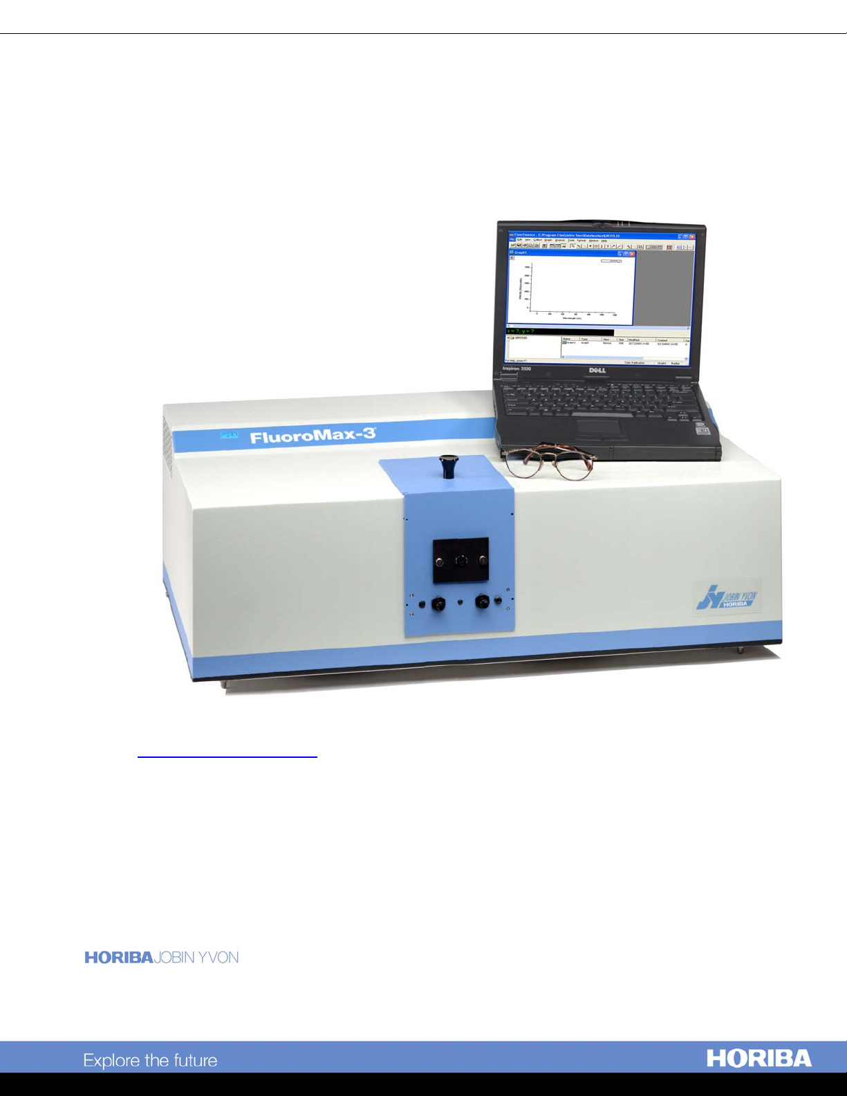
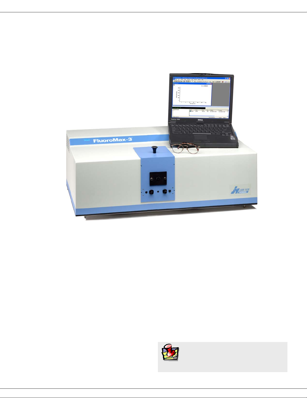
Both the FluoroMax®-3 and FluoroMax®-P are self-contained, fully automated spectrofluorometer systems. Data output is viewed on a PC, while printouts may be obtained
via an optional plotter or printer. All FluoroMax®-3 and FluoroMax®-P functions are
under the control of FluorEssence™ spectroscopy software. The main parts of the
FluoroMax®-3 and FluoroMax®-P spectrofluorometer systems are:
• State-of-the-art optical components
• A personal computer
• FluorEssence™ for Windows™, the driving software.
The difference between the FluoroMax®-3 and FluoroMax®-P is that the FluoroMax®-P
contains a phosphorimeter for phosphorescence measurements. This manual explains
how to operate and maintain a FluoroMax
The manual also describes measurements and tests essential to obtain accurate data. For
a complete discussion of the almost limitless power provided by FluorEssence™, refer
to the FluorEssence™ User’s Guide (especially regarding software installation) and the
on-line help for Origin
®
and FluorEssence™, which accompany the system.
®
-3 and FluoroMax®-P spectrofluorometer.
Note:
manuals near the system.
Keep this and the other reference
0-1

FluoroMax-3 v. 3.1 (3 Mar 2006) Introduction
Chapter overview
1: Requirements & Installation
2: System Description
3: System Operation
4: Data Acquisition
5: Optimizing Data Acquisition
6: System Maintenance
7: Troubleshooting
Power and environmental requirements;
select the best spot for the instrument.
How the FluoroMax®-3 and -P work.
Operation of the spectrofluorometer system,
and calibration instructions.
How to use the special FluorEssence™
buttons to acquire and plot data; how to
determine peaks in an unknown sample.
Hints for improving the signal-to-noise ratio,
instructions for obtaining corrected data, and
other information useful for optimizing data
and ensuring reproducibility.
Routine maintenance procedures such as
replacing the lamp.
Potential sources of problems, their most
probable causes, and possible solutions.
8: Producing Correction Factors
9: FluoroMax®-P Phosphorimeter Operation
10: Automated Polarizers
11: Technical Specifications
12: Components & Accessories
13: Glossary
14: Bibliography
15:
Declaration of Conformity
How to correct for variation in the system’s
sensitivity across the spectral range.
Theory, operation, applications, and
troubleshooting of the phosphorimeter,
available on the FluoroMax®-P system.
Installation, operation, and troubleshooting
of the optional automated polarizers.
Instrument specifications and computer
requirements.
Accessories available for the FluoroMax®-3,
and how to use them.
Some useful technical terms related to
fluorescence spectroscopy.
Other important sources of information.
16: Index
0-2

FluoroMax-3 v. 3.1 (3 Mar 2006) Introduction
Disclaimer
By setting up or starting to use any HORIBA Jobin Yvon product, you are accepting
the following terms:
You are responsible for understanding the information contained in this document. You
should not rely on this information as absolute or all-encompassing; there may be local
issues (in your environment) not addressed in this document that you may need to address, and there may be issues or procedures discussed that may not apply to your situation.
If you do not follow the instructions or procedures contained in this document, you are
responsible for yourself and your actions and all resulting consequences. If you rely on
the information contained in this document, you are responsible for:
• Adhering to safety procedures
• Following all precautions
• Referring to additional safety documentation, such as Material Safety Data Sheets
(MSDS), when advised
As a condition of purchase, you agree to use safe operating procedures in the use of all
products supplied by HORIBA Jobin Yvon, including those specified in the MSDS
provided with any chemicals and all warning and cautionary notices, and to use all
safety devices and guards when operating equipment. You agree to indemnify and hold
HORIBA Jobin Yvon harmless from any liability or obligation arising from your use or
misuse of any such products, including, without limitation, to persons injured directly
or indirectly in connection with your use or operation of the products. The foregoing
indemnification shall in no event be deemed to have expanded HORIBA Jobin Yvon’s
liability for the products.
HORIBA Jobin Yvon products are not intended for any general cosmetic, drug, food, or
household application, but may be used for analytical measurements or research in
these fields. A condition of HORIBA Jobin Yvon’s acceptance of a purchase order is
that only qualified individuals, trained and familiar with procedures suitable for the
products ordered, will handle them. Training and maintenance procedures may be purchased from HORIBA Jobin Yvon at an additional cost. HORIBA Jobin Yvon cannot
be held responsible for actions your employer or contractor may take without proper
training.
Due to HORIBA Jobin Yvon’s efforts to continuously improve our products, all specifications, dimensions, internal workings, and operating procedures are subject to
change without notice. All specifications and measurements are approximate, based on
a standard configuration; results may vary with the application and environment. Any
software manufactured by HORIBA Jobin Yvon is also under constant development
and subject to change without notice.
Any warranties and remedies with respect to our products are limited to those provided
in writing as to a particular product. In no event shall HORIBA Jobin Yvon be held li-
0-3

FluoroMax-3 v. 3.1 (3 Mar 2006) Introduction
able for any special, incidental, indirect or consequential damages of any kind, or any
damages whatsoever resulting from loss of use, loss of data, or loss of profits, arising
out of or in connection with our products or the use or possession thereof. HORIBA
Jobin Yvon is also in no event liable for damages on any theory of liability arising out
of, or in connection with, the use or performance of our hardware or software, regardless of whether you have been advised of the possibility of damage.
0-4
FluoroMax-3 v. 3.1 (3 Mar 2006) Introduction
Safety summary
The following general safety precautions must be observed during all phases of operation of this instrument. Failure to comply with these precautions or with specific warnings elsewhere in this manual violates safety standards of design, manufacture and intended use of instrument. HORIBA Jobin Yvon assumes no liability for the customer’s
failure to comply with these requirements. Certain symbols are used throughout the text
for special conditions when operating the instruments:
A WARNING notice denotes a hazard. It calls
attention to an operating procedure, practice, or
Warning:
similar that, if incorrectly performed or adhered to, could result in personal injury or
death. Do not proceed beyond a WARNING
notice until the indicated conditions are fully
understood and met. HORIBA Jobin Yvon Inc.
is not responsible for damage arising out of
improper use of the equipment.
Caution:
Caution:
Caution:
A CAUTION notice denotes a hazard. It calls
attention to an operating procedure, practice, or
similar that, if incorrectly performed or adhered to, could result in damage to the product.
Do not proceed beyond a CAUTION notice
until the indicated conditions are fully understood and met. HORIBA Jobin Yvon Inc. is not
responsible for damage arising out of improper
use of the equipment.
Ultraviolet light! Wear protective goggles, fullface shield, skin-protection clothing, and UVblocking gloves. Do not stare into light.
Intense ultraviolet, visible, or infrared light!
Wear light-protective goggles, full-face shield,
skin-protection clothing, and light-blocking
gloves. Do not stare into light.
Extreme cold! Cryogenic materials must always be handled with care. Wear protective
Caution:
goggles, full-face shield, skin-protection clothing, and insulated gloves.
0-5
FluoroMax-3 v. 3.1 (3 Mar 2006) Introduction
Explosion hazard! Wear explosion-proof goggles, full-face shield, skin-protection clothing,
Warning:
and protective gloves.
Risk of electric shock! This symbol warns the
user that uninsulated voltage within the unit
Warning:
may have sufficient magnitude to cause electric
shock.
Danger to fingers! This symbol warns the user
that the equipment is heavy, and can crush or
Warning:
injure the hand if precautions are not taken.
This symbol cautions the user that excessive
humidity, if present, can damage certain
Caution:
equipment.
Hot! This symbol warns the user that hot equipment may be present, and could create a risk
Warning:
of fire or burns.
Read this manual before using or servicing the
instrument.
Wear protective gloves.
0-6
FluoroMax-3 v. 3.1 (3 Mar 2006) Introduction
Wear appropriate safety goggles to protect the
eyes.
Wear an appropriate face-shield to protect the
face.
Note:
tion of the equipment.
General information is given concerning opera-
0-7
FluoroMax-3 v. 3.1 (3 Mar 2006) Introduction
Risks of ultraviolet exposure
Do not aim the UV light at anyone.
Do not look directly into the light.
Always wear protective goggles, full-face shield and skin protection clothing and
gloves when using the light source.
• Light is subdivided into visible light, ranging from 400 nm (violet) to 700 nm (red);
longer infrared, “above red” or > 700nm, also called heat; and shorter ultraviolet radiation (UVR), “below violet” or < 400nm. UVR is further subdivided into UV-A
or near-UV (320–400 nm), also called black (invisible) light; UV-B or mid-UV
(290–320 nm), which is more skin penetrating; and UV-C or far-UV (< 290 nm).
• Health effects of exposure to UV light are familiar to anyone who has had sunburn.
However, the UV light level around some UV equipment greatly exceeds the level
found in nature. Acute (short-term) effects include redness or ulceration of the skin.
At high levels of exposure, these burns can be serious. For chronic exposures, there
is also a cumulative risk of harm. This risk depends upon the amount of exposure
during your lifetime. The long-term risks for large cumulative exposure include
premature aging of the skin, wrinkles and, most seriously, skin cancer and cataract.
• Damage to vision is likely following exposure to high-intensity UV radiation. In
adults, more than 99% of UV radiation is absorbed by the anterior structures of the
eye. UVR can contribute to the development of age-related cataract, pterygium,
photodermatitis, and cancer of the skin around the eye. It may also contribute to
age-related macular degeneration. Like the skin, the covering of the eye or the cornea, is epithelial tissue. The danger to the eye is enhanced by the fact that light can
enter from all angles around the eye and not only in the direction of vision. This is
especially true while working in a dark environment, as the pupil is wide open. The
lens can also be damaged, but because the cornea acts as a filter, the chances are re-
Caution:
traviolet light. Exposure to these radiations, even reflected or diffused, can result in serious, and sometimes
irreversible, eye and skin injuries.
Overexposure to ultraviolet rays threatens human
health by causing:
This instrument is used in conjunction with ul-
• Immediate painful sunburn
• Skin cancer
• Eye damage
• Immune-system suppression
• Premature aging
0-8
FluoroMax-3 v. 3.1 (3 Mar 2006) Introduction
duced. This should not lessen the concern over lens damage however, because cataracts are the direct result of lens damage.
Burns to the eyes are usually more painful and serious than a burn to the skin. Make
sure your eye protection is appropriate for this work. NORMAL EYEGLASSES OR
CONTACTS OFFER VERY LIMITED PROTECTION!
Warning:
user may not realize the hazard until it is too late and
the damage is done.
UV exposures are not immediately felt. The
Training
For the use of UV sources, new users must be trained by another member of the laboratory who, in the opinion of the member of staff in charge of the department, is sufficiently competent to give instruction on the correct procedure. Newly trained users
should be overseen for some time by a competent person.
0-9
FluoroMax-3 v. 3.1 (3 Mar 2006) Introduction
Additional risks of xenon lamps
Warning:
are dangerous.
Please read the fol-
Among the dangers associated with xenon lamps
are:
• Burns caused by contact with a hot xenon lamp.
• Fire ignited by hot xenon lamp.
• Interaction of other nearby chemicals with intense ultraviolet, visible, or infrared
radiation.
• Damage caused to apparatus placed close to the xenon lamp.
• Explosion or mechanical failure of the xenon lamp.
lowing precautions.
Xenon lamps
Visible radiation
Any very bright visible light source will cause a human aversion response: we either
blink or turn our head away. Although we may see a retinal afterimage (which can last
for several minutes), the aversion response time (about 0.25 seconds) normally protects
our vision. This aversion response should be trusted and obeyed. NEVER STARE AT
ANY BRIGHT LIGHT-SOURCE FOR AN EXTENDED PERIOD. Overriding the
aversion response by forcing yourself to look at a bright light-source may result in permanent injury to the retina. This type of injury can occur during a single prolonged exposure. Excessive exposure to visible light can result in skin and eye damage.
Visible light sources that are not bright enough to cause retinal burns are not necessarily safe to view for an extended period. In fact, any sufficiently bright visible light
source viewed for an extended period will eventually cause degradation of both night
and color vision. Appropriate protective filters are needed for any light source that
causes viewing discomfort when viewed for an extended period of time. For these reasons, prolonged viewing of bright light sources should be limited by the use of appropriate filters.
The blue-light wavelengths (400–500 nm) present a unique hazard to the retina by causing photochemical effects similar to those found in UV-radiation exposure.
Infrared radiation
Infrared (or heat) radiation is defined as having a wavelength between 780 nm and 1
mm. Specific biological effectiveness “bands” have been defined by the CIE (Commission International de l’Eclairage or International Commission on Illumination) as follows:
• IR-A (near IR) (780–1400 nm)
• IR-B (mid IR) (1400– 3000 nm)
0-10

FluoroMax-3 v. 3.1 (3 Mar 2006) Introduction
• IR-C (far IR) (3000 nm–1 mm)
The skin and eyes absorb infrared radiation (IR) as heat. Workers normally notice excessive exposure through heat sensation and pain. Infrared radiation in the IR-A that
enters the human eye will reach (and can be focused upon) the sensitive cells of the retina. For high irradiance sources in the IR-A, the retina is the part of the eye that is at
risk. For sources in the IR-B and IR-C, both the skin and the cornea may be at risk from
“flash burns.” In addition, the heat deposited in the cornea may be conducted to the lens
of the eye. This heating of the lens is believed to be the cause of so called “glassblowers’ ” cataracts because the heat transfer may cause clouding of the lens.
• Retinal IR Hazards (780 to 1400 nm): possible retinal lesions from acute high ir-
radiance exposures to small dimension sources.
• Lens IR Hazards (1400 to 1900 nm): possible cataract induction from chronic lower
irradiance exposures.
• Corneal IR Hazards (1900 nm to 1 mm): possible flashburns from acute high irradi-
ance exposures.
Who is likely to be injured? The user and anyone exposed to the radiation or xenon
lamp shards as a result of faulty procedures. Injuries may be slight to severe.
0-11

FluoroMax-3 v. 3.1 (3 Mar 2006) Introduction
0-12

FluoroMax-3 v. 3.1 (3 Mar 2006) Requirements & Installation
1: Requirements & Installation
Safety-training requirements
Every user of the FluoroMax®-3 and FluoroMax®-P must know general and specific
safety procedures before operating the instrument. For example, proper training includes (but is not limited to):
• Understanding the risks of exposure to ultraviolet, visible, and infrared light, and
how to avoid unsafe exposures to these types of radiation
• Handling xenon-lamp bulbs, and their dangers
• Safe handling for all chemicals and other samples used in the instrument
Safety-training may be purchased from HORIBA Jobin Yvon. Contact your Spex
Fluorescence Representative or the Fluorescence Service Department for details.
®
1-1

FluoroMax-3 v. 3.1 (3 Mar 2006) Requirements & Installation
Surface requirements
• A sturdy table- or bench-top.
• Surface must hold 90 kg (200 lbs.).
• Surface should be about 27" × 72" (69 cm × 183 cm) to hold spectrofluorometer,
computer, and accessories comfortably.
• Overhead clearance should be at least 36" (91 cm).
1-2
FluoroMax-3 v. 3.1 (3 Mar 2006) Requirements & Installation
Environmental requirements
• Temperature 59–86°F (15–30°C)
• Maximum temperature fluctuation ± 2°C
• Ambient relative humidity < 75%
Caution:
• Low dust levels
• No special ventilation
Warning:
Excessive humidity can damage the optics.
For adequate cooling, do not cover, block, or
obstruct the vents on the left side and underside of the
instrument.
1-3
FluoroMax-3 v. 3.1 (3 Mar 2006) Requirements & Installation
u
Electrical requirements
• 110 VAC ± 5%, 60 Hz; or 220 VAC ± 5%, 50 Hz
• Have enough outlets available for:
Host computer (PC)
Monitor
Optional printer
FluoroMax®-3
Each of certain accessories, such the MicroMax, temperature bath, etc.
Warning:
damage from line surges and voltage fluctuations.
A surge protector is strongly recommended for minor power fluctuations. For more severe voltage
variations, use a generator or uninterruptible power
supply. Improper line voltages can damage the
equipment severely.
Warning:
three-conductor power cord that is connected to the
system frame (earth) ground. This ground provides
a return path for fault current from equipment malfunction or external faults. For all instruments,
ground continuity is required for safe operation. Any
discontinuity in the ground line can make the instrument unsafe for use. Do not operate this sys-
tem from an
HORIBA Jobin Yvon Inc. is not liable for
The FluoroMax®-3 is equipped with a
ngrounded source.
Note:
HORIBA Jobin Yvon Inc. recommends connecting the host
computer, monitor, and printer to a single surge-protector, to
make start-up more convenient, and to conserve AC outlets.
Connect the FluoroMax
late the xenon-lamp power supply inside the FluoroMax
®
-3 to a separate line, if possible, to iso-
1-4
®
-3.
FluoroMax-3 v. 3.1 (3 Mar 2006) Requirements & Installation
Unpacking and installation
Introduction
The FluoroMax®-3 spectrofluorometer system is delivered in a single packing carton. If
a host computer (PC) is ordered as a part of the system, the PC is delivered in a few
clearly labeled boxes. All accessories, cables, software, and manuals ordered with the
system are included with the delivery.
Examine the shipping boxes carefully. Any evidence of damage should be noted on the
delivery receipt and signed by representatives of the receiving and carrier companies.
Once a location has been chosen, unpack and assemble the equipment as described below. To avoid excessive moving and handling, the equipment should be unpacked as
close as possible to the selected location.
Note:
Many public carriers will not recognize a claim for concealed
damage if it is reported later than 15 days after delivery. In case of a
claim, inspection by an agent of the carrier is required. For this reason, the original packing material should be retained as evidence of
alleged mishandling or abuse. While HORIBA Jobin Yvon Inc. assumes no responsibility for damage occurring during transit, the company will make every effort to aid and advise.
Caution:
instrument. Mishandling may seriously damage its
components.
The spectrofluorometer system is a delicate
FluoroMax®-3 carton contents
Quantity Item Part number
1 FluoroMax®-3
1 Null modem communications cable 400144
1
1 Laminated safety summary card 81106
1 Set of Allen wrenches 53057
1 Single-cell sample-holder 351697
1 Power cord (110 V)
1 FluorEssence™ software package
FluoroMax®-3 Operation Manual
(220 V)
81038
98015
98020
1-5
FluoroMax-3 v. 3.1 (3 Mar 2006) Requirements & Installation
1 Unpack and set up the FluoroMax
a Carefully open the FluoroMax
®
-3 shipping carton.
b Remove the foam-injected top piece and any other shipping restraints in
the carton.
c With assistance, carefully
lift the instrument from the
carton, and rest it on the
side of the laboratory bench
where the system will stay.
d Place the instrument in its permanent location.
e Level the spectrofluorometer.
Adjust the four leveling feet on the bottom of the instrument.
f Inspect for previously hidden damage.
Notify the carrier and HORIBA Jobin Yvon Inc. if any is found.
g Check the packing list to verify that all components and accessories are
present.
®
.
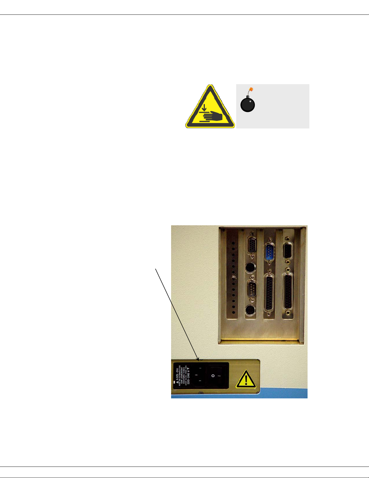
Warning:
your fingers!
Watch
h Plug one end of the
power cord into the
proper receptacle on
the left side (while
facing the unit) of the
spectrofluorometer.
1-6
FluoroMax-3 v. 3.1 (3 Mar 2006) Requirements & Installation
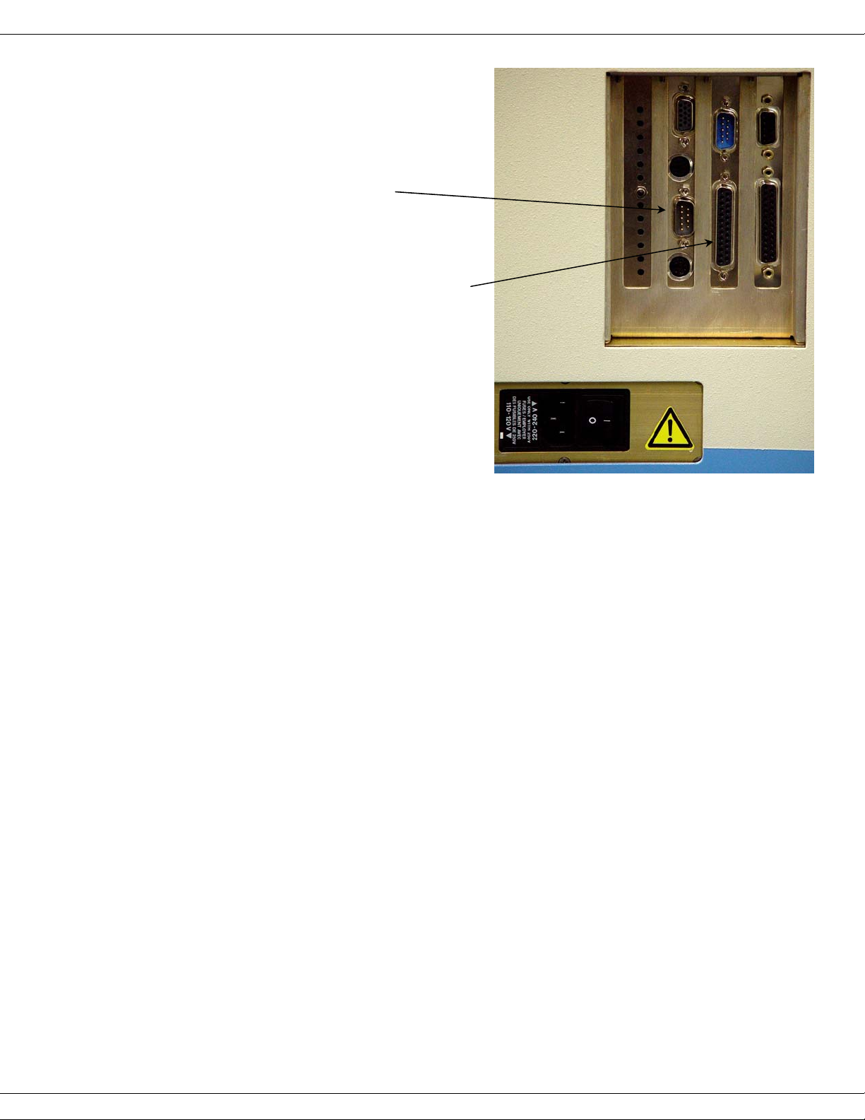
i Plug one end of the 9-
pin communications
cable into this 9-pin
connector (COM1) on
the FluoroMax
right panel.
®
-3’s
j With an optional
trigger accessory, plug
one end of the trigger
cable into this 25-pin
connector on the
FluoroMax®-3.
Allow the unconnected ends of
the cables to dangle freely;
they will be connected in later
steps.
2 Set up the computer.
The information gathered by the spectrofluorometer system is displayed and
controlled through the host PC via FluorEssence™ software. The host PC may
be purchased from HORIBA Jobin Yvon Inc. or another supplier.
a Set up the host PC reasonably close to the FluoroMax
limitation is the length of the null modem communications cable. The
recommended location for the PC is just to the right of the spectro-
fluorometer, but other positions are possible.
b Follow the instructions for the host PC to set up the computer system,
including the CPU, monitor, keyboard, mouse, speakers, printers, etc.
3 Connect the FluoroMax
a Attach the free end of the communication cable to COM1 (first serial
port) of the computer.
If COM1 is not available, then use an unused serial port (COM) on the host
computer. If only a 25-pin connector is available, use a standard 25-pin–9-pin
converter, or contact Spex® Fluorescence Service for assistance. During software installation, the serial port setting used on the host computer to communicate with the FluoroMax®-3 is entered.
®
-3 system. The
®
to the computer.
b With all devices OFF, plug the power cords from the monitor, computer,
FluoroMax®, and the printer into properly grounded receptacles.
c If a Trigger-box accessory is included, attach the free end of the Trigger-
box cable to the Trigger box.
1-7
FluoroMax-3 v. 3.1 (3 Mar 2006) Requirements & Installation
d Install any accessories that arrived with the system, using the instruc-
tions that accompany the accessories.
See Chapter 12 for a detailed list of accessories.
4 Install the FluorEssence™ software.
The spectrofluorometer system is controlled by FluorEssence™ spectroscopy
software operating within the Windows™ environment. If the computer and
software were purchased from HORIBA Jobin Yvon Inc., the software installation is complete. If the computer is not from HORIBA Jobin Yvon Inc., perform
the installation. Contact a HORIBA Jobin Yvon Inc. Sales Representative for
recommended specifications for a suitable host computer.
Before the FluorEssence™ software can be installed, however, Windows™
must be installed already and operating properly. Refer to the Windows™ manual that came with the computer for installation instructions.
The FluorEssence™ software is supplied on one CD-ROM. Follow the
FluorEssence™ User’s Guide for details on installation.
Note:
Be sure to agree to the terms of the software license be-
fore using the software.
Users outside of the USA:
Users outside of the USA receive a softkey device that connects to the printer port of
the host computer for software security. The softkey should be left in place on the host
computer at all times.
Note:
Copying, disassembly, or removal of the softkey is illegal.
1-8
FluoroMax-3 v. 3.1 (3 Mar 2006) Requirements & Installation
Software emulation
Emulating the FluorEssence™ software means letting the computer act as though the
FluoroMax
®
is properly connected, even if it isn’t.
1 Disconnect the communications cable from the
host computer to the FluoroMax
Note:
Be sure the FluorEssence™ USB key is inserted into a free
USB port on the host computer. Without the key, FluorEssence™ will not run properly, even in emulation mode.
®
.
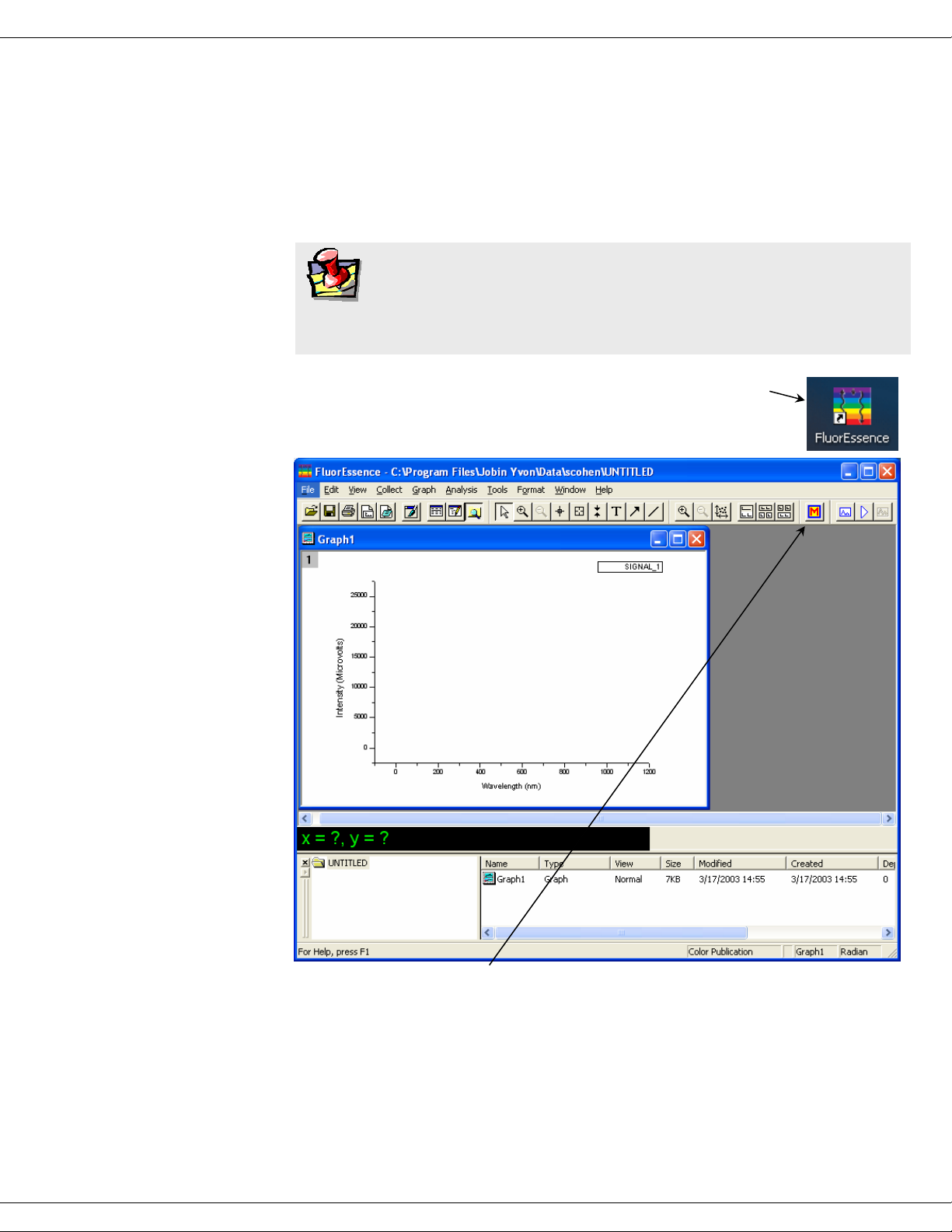
2 Double-click the FluorEssence icon to
start FluorEssence™.
The main
FluorEssence
window opens:
3 Click the Monos button to open a hardware con-
figuration.
The
Select Hardware Configuration
window opens.
1-9
FluoroMax-3 v. 3.1 (3 Mar 2006) Requirements & Installation
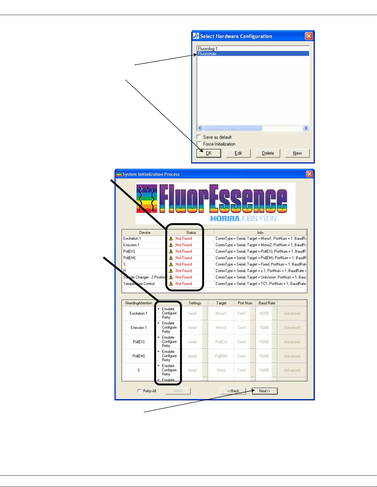
4 Choose the desired
instrument you wish
to emulate.
5 Click OK.
The
System Initialization Process
opens:
Under the Status
column, warning
symbols appear
for the hardware
devices, noting
that they were
Not Found. Thus
FluorEssence™
chooses the
Emulate radio
button as the
default action for
each device.
window
6 Click Next>>.
The
Fluorescence Main Experiment Menu
lating the instrument.
appears. FluorEssence™ is now emu-
1-10
FluoroMax-3 v. 3 (22 Feb 2005) System Description
2: System Description
Warning:
having read this operation manual. The instrument contains dangerous voltages, ultraviolet, visible, and infrared radiation, and
fragile light-sources. In addition, tampering with the optical components can irreversibly damage them.
Do not open the instrument without proper training and
Introduction
A spectrofluorometer is an analytical instrument used to measure and record the fluorescence of a sample. While recording the fluorescence, the excitation, emission, or
both wavelengths may be scanned. With additional accessories, variation of signal with
time, temperature, concentration, polarization, or other variables may be monitored.
Basic theory of operation
A continuous source of light shines onto an excitation monochromator, which selects a
band of wavelengths. This monochromatic excitation light is directed onto a sample,
which emits luminescence. The luminescence is directed into a second, emission monochromator, which selects a band of wavelengths, and shines them onto a detector. The
signal from the detector is reported to a system controller and host computer, where the
data can be manipulated and presented, using special software.
2-1
FluoroMax-3 v. 3 (22 Feb 2005) System Description
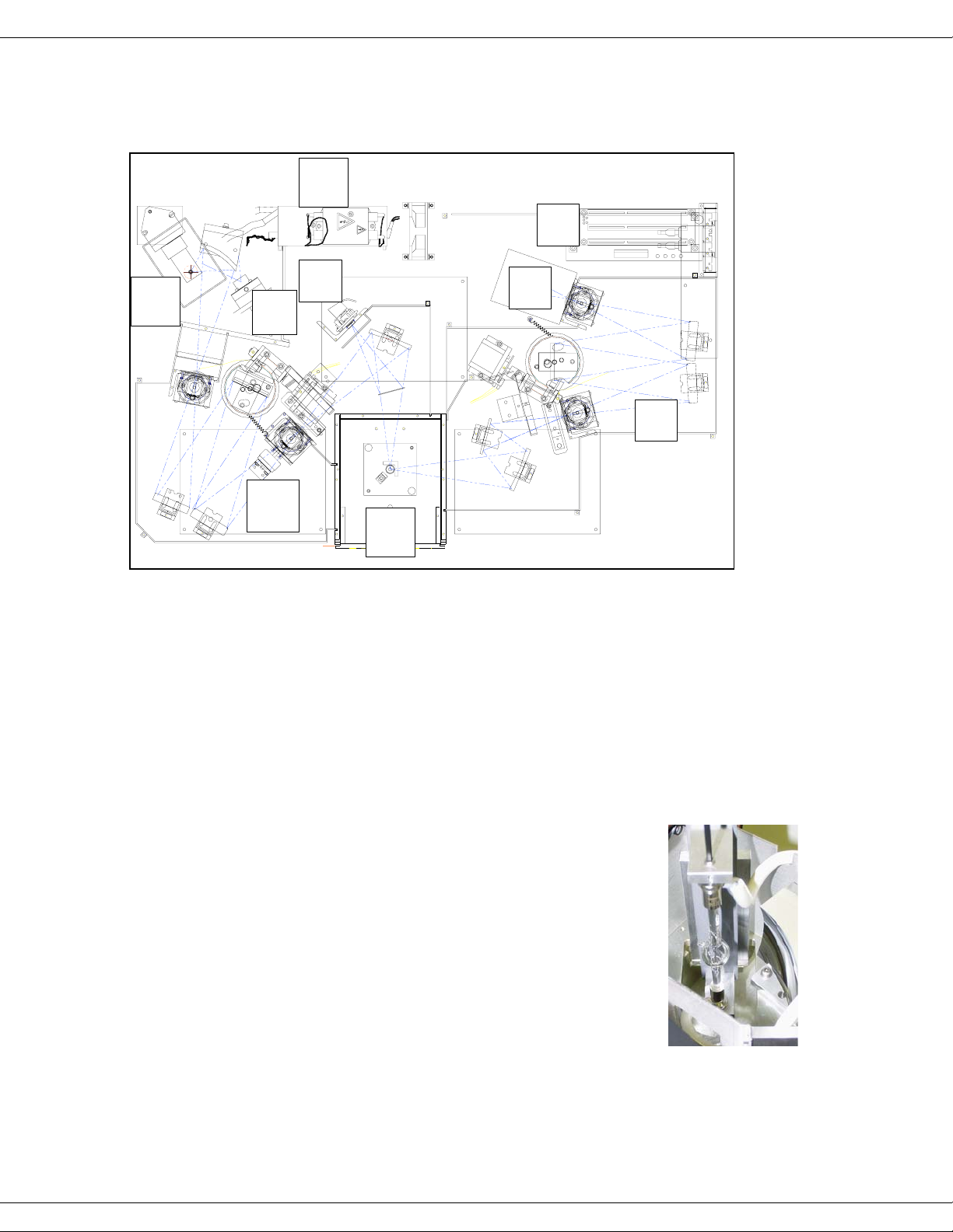
Optical layout
1a
7
1
6
1b
5
4
2
3
1 Xenon arc-lamp and lamp housing
1a Xenon-lamp power supply
1b Xenon flash lamp (FluoroMax®-P only)
2 Excitation monochromator
3 Sample compartment
4 Emission monochromator
5 Signal detector (photomultiplier tube and housing)
6 Reference detector (photodiode and current-acquisition module)
7 Instrument controller
Host computer (not on diagram)
Illuminator (xenon arc-lamp, 1)
The continuous light source is a 150-W ozone-free xenon arc-lamp.
Light from the lamp is collected by a diamond-turned elliptical
mirror, and then focused on the entrance slit of the excitation
monochromator. A portion of the light is directed upward to the
®
Spex
indicator on the front panel. The lamp housing is separated from the
excitation monochromator by a quartz window. This vents heat out
of the instrument, and protects against the unlikely occurrence of
lamp failure.
logo on the instrument cover, to provide a “lamp on”
2-2
 Loading...