

horiba Fluorolog-3 Operation Manual

Fluorolog-3 v. 3.2 (2 May 2008)
Fluorolog-3 v. 3.2 (2 May 2008)
Fluorolog®-3 with
FluorEssence™
Operation Manual
Rev. 3.2
http://www.jobinyvon.com
(All HORIBA Jobin Yvon co mpanies w ere form erly know n as Jobi n Yvon)
USA:
Tel: +1-732-494-8660, Fax: +1-732-549-5125, E-mail: info@jobinyvon.com, www.jobinyvon.com
France:
Tel: +33 (0) 1 64 54 13 00
Japan:
Chiyoda-ku, Tokyo 101-0031, Tel: +81 (0) 3 3861 8231, www.jyhoriba.jp
Germany:
China:
HORIBA Jobin Yvon Inc., 3880 Park Avenue, Edison, NJ 08820-3012, Toll-Free:
HORIBA Jobin Yvon S.A.S., 16-18, rue du Canal, 91165 Longjumeau Cedex,
HORIBA Ltd., JY Optical Sales Dept, Higashi-Kanda, Daiji Building, 1-7-8 Higashi-Kanda
+49 (0) 89 462317-0
+86 (0) 10 6849 2216
,
Fax: +33 (0) 1 69 09 93 19, www.jobinyvon.fr
Italy:
+39 0 2 57603050
UK:
+1-866-jobinyvon
+44 (0) 20 8204 8142

Fluorolog-3 v. 3.2 (2 May 2008)
Copyright © 2002, 2005–2006, 2008 by HORIBA
Jobin Yvon Inc.
All rights reserved. No part of this work may be
reproduced, stored, in a retrieval system, or
transmitted in any form by any means, including
electronic or mechanical, photocopying and
recording, without prior written permission from
HORIBA Jobin Yvon Inc. Requests for permission
should be requested in writing. Origin® is a registered
trademark of OriginLab Corporation. Alconox® is a
registered trademark of Alconox, Inc. Ludox® is a
registered trademark of W.R. Grace and Co. Teflon®
is a registered trademark of E.I. du Pont de Nemours
and Company. Windows® and Excel® are registered
trademarks of Microsoft Corporation.
Information in this manual is subject to change
without notice, and does not represent a commitment
on the part of the vendor.
May 2008
Part Number 81014
ii

Fluorolog-3 v. 3.2 (2 May 2008)
Table of Contents
0: Introduction ................................................................................................0-1
About the Fluorolog®-3............................................................................................................................0-1
Chapter overview....................................................................................................................................0-2
Disclaimer...............................................................................................................................................0-4
Safety summary......................................................................................................................................0-6
Risks of ultraviolet exposure...................................................................................................................0-9
Additional risks of xenon lamps............................................................................................................0-11
1: Requirements & Installation ............................................................................1-1
Surface requirements .............................................................................................................................1-1
Environmental requirements...................................................................................................................1-2
Electrical requirements ...........................................................................................................................1-3
Installation...............................................................................................................................................1-4
2: System Description ....................................................................................... 2-1
Overview.................................................................................................................................................2-1
Configurations.........................................................................................................................................2-3
3: System Operation ......................................................................................... 3-1
Turning on the system............................................................................................................................3-1
Checking system performance...............................................................................................................3-3
Useful materials for characterizing system and samples.....................................................................3-16
4: Data Acquisition........................................................................................... 4-1
Experiment Menu button.........................................................................................................................4-2
Previous Experiment Setup button.........................................................................................................4-4
Auto Run Previous Experiment button ...................................................................................................4-5
Make Overlay File button........................................................................................................................4-6
3D Scan to 3D Profile button..................................................................................................................4-7
Run JY Batch Experiments button..........................................................................................................4-9
Real Time Control button......................................................................................................................4-11
Create/Use Calibration Curve from CWA Data button .........................................................................4-12
2D Intensity Map button........................................................................................................................4-16
Gemini Alpha button .............................................................................................................................4-17
Gemini Alpha results button..................................................................................................................4-18
Launch DataStation button...................................................................................................................4-19
Running an unknown sample ...............................................................................................................4-20
Using corrected signals in FluorEssence™..........................................................................................4-25
5: Optimizing Data ...........................................................................................5-1
Cuvette preparation ................................................................................................................................5-1
Sample preparation ................................................................................................................................5-2
Running a scan on a sample..................................................................................................................5-4
Data collection techniques......................................................................................................................5-6
Correcting data .....................................................................................................................................5-12
6: System Maintenance .....................................................................................6-1
External Case .........................................................................................................................................6-1
Xenon lamp.............................................................................................................................................6-1
Installing an optional new photomultiplier tube.....................................................................................6-15
Reference signal detector.....................................................................................................................6-16
Gratings ................................................................................................................................................6-17
Mirrors...................................................................................................................................................6-21
Automated 4-position turret ..................................................................................................................6-22
iii

Fluorolog-3 v. 3.2 (2 May 2008)
7: Troubleshooting........................................................................................... 7-1
Chart.......................................................................................................................................................7-1
Using diagnostic spectra ........................................................................................................................7-3
Further assistance…...............................................................................................................................7-8
8: Producing Correction Factors ........................................................................... 8-1
Introduction.............................................................................................................................................8-1
Types of Correction-Factor Kits..............................................................................................................8-2
Generating emission correction factors via 1908 accessory..................................................................8-3
Calculating emission correction factors via 1908 accessory................................................................8-11
Generating emission correction factors via F-3026 accessory ............................................................ 8-13
Calculating excitation correction factors...............................................................................................8-20
Using correction-factor files..................................................................................................................8-24
9: Automated Polarizers .................................................................................... 9-1
Introduction.............................................................................................................................................9-1
Installation...............................................................................................................................................9-6
Alignment................................................................................................................................................9-7
Using automated polarizers..................................................................................................................9-15
Measuring the G factor.........................................................................................................................9-20
Maintenance.........................................................................................................................................9-22
Troubleshooting....................................................................................................................................9-23
10: Phosphorimeter Operation............................................................................10-1
Introduction...........................................................................................................................................10-1
Theory of operation...............................................................................................................................10-2
Applications for the phosphorimeter.....................................................................................................10-5
Installation.............................................................................................................................................10-8
Operation of the phosphorimeter................................................................................................ ..........10-9
Processing phosphorimeter data........................................................................................................10-11
Lamp replacement..............................................................................................................................10-12
Troubleshooting..................................................................................................................................10-18
Phosphorimeter trigger.......................................................................................................................10-19
11: Applications.............................................................................................11-1
Introduction...........................................................................................................................................11-1
Detecting sub-picomolar concentrations of fluorescein........................................................................11-3
Reduced-volume samples....................................................................................................................11-3
Fluorescence detection of highly scattering samples...........................................................................11-4
Quantum-yield calculations ..................................................................................................................11-4
Characterizing complex mixtures via synchronous scanning...............................................................11-5
Operating in the IR region ....................................................................................................................11-5
Phosphorescence for time-resolved data.............................................................................................11-6
Low-temperature scans........................................................................................................................11-7
Monitoring kinetic reactions using time-based fluorescence................................................................11-7
Front-face detection to enhance data collection for absorbent or solid samples.................................11-7
Polarization to detect trace quantities of biological probes..................................................................11-8
12: Xenon Lamp Information & Record of Use Form ..................................................12-1
Xenon Lamp Record of Use.................................................................................................................12-3
13: TRIAX Operation with the Fluorolog®-3.............................................................13-1
Introduction...........................................................................................................................................13-1
Hardware..............................................................................................................................................13-2
Software................................................................................................................................................13-5
System Configuration
Correcting data with the TRIAX..........................................................................................................13-15
TRIAX 320 Specifications...................................................................................................................13-23
Troubleshooting..................................................................................................................................13-24
window................................................................................................................. 13-13
iv

Fluorolog-3 v. 3.2 (2 May 2008)
14: Introduction to lifetime measurements ............................................................ 14-1
Introduction...........................................................................................................................................14-1
Lifetime measurements ........................................................................................................................14-2
Types of lifetime scans .........................................................................................................................14-4
15: Technical Specifications ............................................................................. 15-1
Spectrofluorometer system...................................................................................................................15-2
Minimum computer requirements.........................................................................................................15-4
Software................................................................................................................................................15-4
16: Components & Accessories .......................................................................... 16-1
Itemized list...........................................................................................................................................16-2
FL-1013 Liquid Nitrogen Dewar Assembly...........................................................................................16-3
1908MOD Scatter Block Assembly.......................................................................................................16-4
1908 Standard Lamp Assembly............................................................................................................16-4
Sample cells..........................................................................................................................................16-5
F-3026 Correction Factor Kit ................................................................................................................16-6
CM-MH Monolayer coverslip ................................................................................................................16-7
F-3023 Janis cryostat ...........................................................................................................................16-8
1967 Photodiode Reference Detector..................................................................................................16-9
CCD Detectors....................................................................................................................................16-10
1911F Room Temperature Signal Detector........................................................................................16-11
1914F Thermoelectrically Cooled Signal Detector.............................................................................16-12
FL-1030 Thermoelectrically Cooled Near-IR Photomultiplier Tube....................................................16-13
F-3000 Fiber Optic Mount and 1950 Fiber Optic Bundles..................................................................16-14
1938 and 1939 Cut-On UV-Visible Filters ..........................................................................................16-15
FL-1010 Cut-On Filter Holder.............................................................................................................16-16
Fl-1001 Front-Face Viewing Option....................................................................................................16-17
Gratings ..............................................................................................................................................16-18
FL-1011 Four-Position Thermostatted Cell Holder.............................................................................16-19
FL-1012 Dual-Position Thermostatted Cell Holder.............................................................................16-21
FL-1027 Single-Position Thermostatted Cell Holder..........................................................................16-23
1933 Solid Sample Holder..................................................................................................................16-25
FL-1039 Xenon Lamp Housing...........................................................................................................16-27
FL-1040 Dual Lamp Housing..............................................................................................................16-27
F-3005/6 Autotitration Injector ............................................................................................................16-28
Microscope Interface ..........................................................................................................................16-29
1907 450-W Xenon Lamp...................................................................................................................16-30
FC-OP-LIO1 and FC-OP-LIO2 Laser Input Optics accessories.........................................................16-31
F-3004 Sample Heater/Cooler Peltier Thermocouple Drive...............................................................16-32
Phosphorimeter Accessory.................................................................................................................16-33
MicroMax 384 Microwell Plate Reader...............................................................................................16-34
FL-1044 L-Format Polarizer & FL-1045 T-Format Polarizer ..............................................................16-35
FL-1015 Injector Port..........................................................................................................................16-36
Quantum-Yield accessory...................................................................................................................16-37
SFA-20/SPEX Stopped-flow accessory..............................................................................................16-38
TCSPC upgrades FL-1054, FL-1057, FL-1065, and FL-1066............................................................16-39
F-1000/1 Temperature Bath ...............................................................................................................16-40
TRIG-15/25 external trigger accessory...............................................................................................16-41
FL-1024 Windows on the Fluorolog
®
-3 sample compartment............................................................16-42
17: Reassemby Instructions .............................................................................. 17-1
Host computer.......................................................................................................................................17-1
Spectrofluorometer assembly...............................................................................................................17-2
Cable connections ................................................................................................................................17-3
Connecting power cables .....................................................................................................................17-7
18: Glossary ................................................................................................ 18-1
v

Fluorolog-3 v. 3.2 (2 May 2008)
19: Bibliography ............................................................................................19-1
20: Index .....................................................................................................20-1
vi
Fluorolog-3 v. 3.2 (2 May 2008) Introduction
0: Introduction
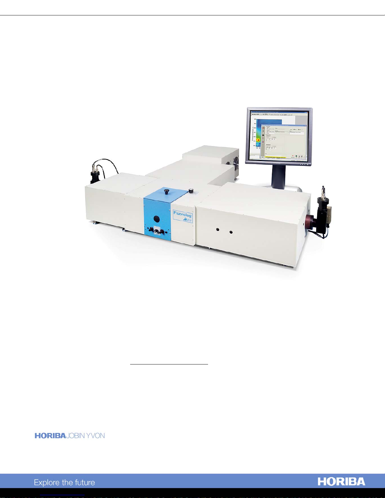
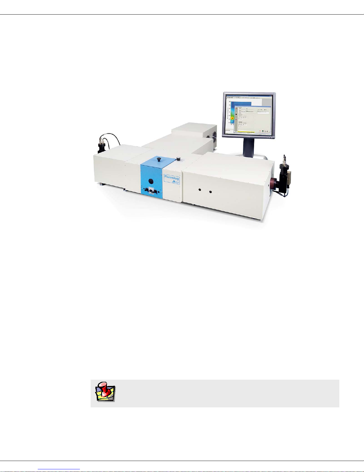
About the Fluorolog®-3
The main parts of the Fluorolog®-3 spectrofluorometer system are:
• State-of-the-art optical components
• A personal computer
• FluorEssence™ for Windows®, the driving software.
This manual explains how to operate and maintain a Fluorolog®-3 spectrofluorometer.
The manual also describes measurements and tests essential to obtain accurate data. For
a complete discussion of the almost limitless power provided by FluorEssence™, refer
to the FluorEssence™ User’s Guide and on-line help, and the Origin® on-line help
(contains post-processing instructions for data manipulation) which accompany the
system.
The combination of time-tested, performance-proven hardware with the powerful dataacquisition and manipulation software yields a system suitable for a wide variety of
applications. Equipped with expansion ports and slots, the Fluorolog
meet the changing needs of the user, it will provide years of dedicated service, and can
be updated easily to the Fluorolog®-Tau-3.
Note:
Keep this and the other reference manuals near the system.
®
-3 can grow to
0-1

Fluorolog-3 v. 3.2 (2 May 2008) Introduction
-
2
Chapter overview
1: Requirements &
Installation
2: System Description
3: System Operation
4: Data Acquisition
5: Optimizing Data
6: System Maintenance
7: Troubleshooting
8: Producing Correction
Factors
Power and environmental requirements; select the best spot for
the instrument.
Various Fluorolog®-3 configurations; their features and
benefits.
Operation of the spectrofluorometer system, and calibration
instructions.
How to use the special FluorEssence™ buttons to acquire and
plot data; how to determine peaks in an unknown sample.
Hints for improving the signal-to-noise ratio, instructions for
obtaining corrected data, and other information useful for
optimizing data and ensuring reproducibility.
Routine maintenance procedures such as replacing the lamp.
Potential sources of problems, their most probable causes, and
possible solutions.
How to correct for variation in sensitivity across the spectral
range.
9: Automated Polarizers
10: Applications
11: Xenon Lamp
Information & Record of
Use Form
12: Using TRIAX with
®
the Fluorolog
-3
13: Introduction to
Lifetime Measurements
14: Technical
Specifications
15: Components &
Accessories
Installation, operation, and troubleshooting of the optional
automated polarizers.
Some interesting uses for the Fluorolog®-3.
Information about the xenon lamp, and a form for recording
the xenon-lamp usage.
Special instructions on using a TRIAX imaging spectrometer
with the Fluorolog®-3 system, including with a CCD detector.
Methods of determining the lifetime of a sample using the
Fluorolog®-Tau-3. The Fluorolog®-Tau-3 is designed
specifically for fluorescence-lifetime applications, and does not
affect steady-state measurements.
Instrument specifications and computer requirements.
Description and application of the accessories available for the
Fluorolog
®
-3.
0

Fluorolog-3 v. 3.2 (2 May 2008) Introduction
-
3
16: Reassembly
Instructions
17: Glossary
18: Bibliography
19: Index
How to reassemble the Fluorolog®-3 after it has been moved.
A list of some useful technical terms related to fluorescence
spectroscopy.
Important sources of information.
0

Fluorolog-3 v. 3.2 (2 May 2008) Introduction
-
4
Disclaimer
By setting up or starting to use any HORIBA Jobin Yvon product, you are accepting
the following terms:
You are responsible for understanding the information contained in this document. You
should not rely on this information as absolute or all-encompassing; there may be local
issues (in your environment) not addressed in this document that you may need to
address, and there may be issues or procedures discussed that may not apply to your
situation.
If you do not follow the instructions or procedures contained in this document, you are
responsible for yourself and your actions and all resulting consequences. If you rely on
the information contained in this document, you are responsible for:
• Adhering to safety procedures
• Following all precautions
• Referring to additional safety documentation, such as Material Safety Data Sheets
(MSDS), when advised
As a condition of purchase, you agree to use safe operating procedures in the use of all
products supplied by HORIBA Jobin Yvon, including those specified in the MSDS
provided with any chemicals and all warning and cautionary notices, and to use all
safety devices and guards when operating equipment. You agree to indemnify and hold
HORIBA Jobin Yvon harmless from any liability or obligation arising from your use or
misuse of any such products, including, without limitation, to persons injured directly
or indirectly in connection with your use or operation of the products. The foregoing
indemnification shall in no event be deemed to have expanded HORIBA Jobin Yvon’s
liability for the products.
HORIBA Jobin Yvon products are not intended for any general cosmetic, drug, food, or
household application, but may be used for analytical measurements or research in
these fields. A condition of HORIBA Jobin Yvon’s acceptance of a purchase order is
that only qualified individuals, trained and familiar with procedures suitable for the
products ordered, will handle them. Training and maintenance procedures may be
purchased from HORIBA Jobin Yvon at an additional cost. HORIBA Jobin Yvon
cannot be held responsible for actions your employer or contractor may take without
proper training.
Due to HORIBA Jobin Yvon’s efforts to continuously improve our products, all
specifications, dimensions, internal workings, and operating procedures are subject to
change without notice. All specifications and measurements are approximate, based on
a standard configuration; results may vary with the application and environment. Any
software manufactured by HORIBA Jobin Yvon is also under constant development
and subject to change without notice.
Any warranties and remedies with respect to our products are limited to those provided
in writing as to a particular product. In no event shall HORIBA Jobin Yvon be held
0

Fluorolog-3 v. 3.2 (2 May 2008) Introduction
-
5
liable for any special, incidental, indirect or consequential damages of any kind, or any
damages whatsoever resulting from loss of use, loss of data, or loss of profits, arising
out of or in connection with our products or the use or possession thereof. HORIBA
Jobin Yvon is also in no event liable for damages on any theory of liability arising out
of, or in connection with, the use or performance of our hardware or software,
regardless of whether you have been advised of the possibility of damage.
0
Fluorolog-3 v. 3.2 (2 May 2008) Introduction
-
6
Safety summary
The following general safety precautions must be observed during all phases of
operation of this instrument. Failure to comply with these precautions or with specific
warnings elsewhere in this manual violates safety standards of design, manufacture and
intended use of instrument. HORIBA Jobin Yvon assumes no liability for the
customer’s failure to comply with these requirements. Certain symbols are used
throughout the text for special conditions when operating the instruments:
A WARNING notice denotes a hazard. It calls
attention to an operating procedure, practice, or
Warning:
similar that, if incorrectly performed or
adhered to, could result in personal injury or
death. Do not proceed beyond a WARNING
notice until the indicated conditions are fully
understood and met. HORIBA Jobin Yvon Inc.
is not responsible for damage arising out of
improper use of the equipment.
Caution:
Caution:
Caution:
A CAUTION notice denotes a hazard. It calls
attention to an operating procedure, practice, or
similar that, if incorrectly performed or
adhered to, could result in damage to the
product. Do not proceed beyond a CAUTION
notice until the indicated conditions are fully
understood and met. HORIBA Jobin Yvon Inc.
is not responsible for damage arising out of
improper use of the equipment.
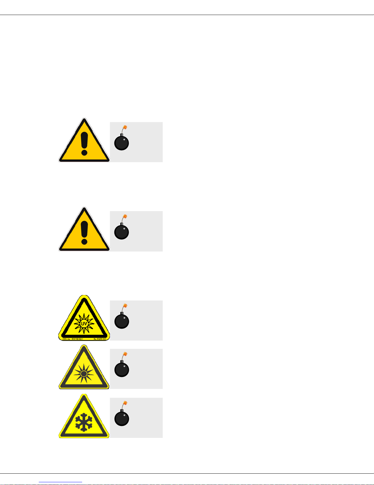
Ultraviolet light! Wear protective goggles, fullface shield, skin-protection clothing, and UVblocking gloves. Do not stare into light.
Intense ultraviolet, visible, or infrared light!
Wear light-protective goggles, full-face shield,
skin-protection clothing, and light-blocking
gloves. Do not stare into light.
Caution:
Extreme cold! Cryogenic materials must
always be handled with care. Wear protective
goggles, full-face shield, skin-protection
clothing, and insulated gloves.
0
Fluorolog-3 v. 3.2 (2 May 2008) Introduction
-
7
Explosion hazard! Wear explosion-proof
goggles, full-face shield, skin-protection
Warning:
clothing, and protective gloves.
Risk of electric shock! This symbol warns the
user that uninsulated voltage within the unit
Warning:
may have sufficient magnitude to cause electric
shock.
Danger to fingers! This symbol warns the user
that the equipment is heavy, and can crush or
Warning:
injure the hand if precautions are not taken.
This symbol cautions the user that excessive
humidity, if present, can damage certain
Caution:
equipment.
Hot! This symbol warns the user that hot
equipment may be present, and could create a
Warning:
risk of fire or burns.
Wear protective gloves.
Wear appropriate safety goggles to protect the
eyes.
0
Fluorolog-3 v. 3.2 (2 May 2008) Introduction
-
8
Wear an appropriate face-shield to protect the
face.
Read this manual before using or servicing the
instrument.
Note:
operation of the equipment.
General information is given concerning
0
Fluorolog-3 v. 3.2 (2 May 2008) Introduction
Risks of ultraviolet exposure
Do not aim the UV light at anyone.
Do not look directly into the light.
Always wear protective goggles, full-face shield and skin protection clothing and
gloves when using the light source.
• Light is subdivided into visible light, ranging from 400 nm (violet) to 700 nm (red);
longer infrared, “above red” or > 700nm, also called heat; and shorter ultraviolet
radiation (UVR), “below violet” or < 400nm. UVR is further subdivided into UV-A
or near-UV (320–400 nm), also called black (invisible) light; UV-B or mid-UV
(290–320 nm), which is more skin penetrating; and UV-C or far-UV (< 290 nm).
• Health effects of exposure to UV light are familiar to anyone who has had sunburn.
However, the UV light level around some UV equipment greatly exceeds the level
found in nature. Acute (short-term) effects include redness or ulceration of the skin.
At high levels of exposure, these burns can be serious. For chronic exposures, there
is also a cumulative risk of harm. This risk depends upon the amount of exposure
during your lifetime. The long-term risks for large cumulative exposure include
premature aging of the skin, wrinkles and, most seriously, skin cancer and cataract.
• Damage to vision is likely following exposure to high-intensity UV radiation. In
adults, more than 99% of UV radiation is absorbed by the anterior structures of the
eye. UVR can contribute to the development of age-related cataract, pterygium,
photodermatitis, and cancer of the skin around the eye. It may also contribute to
age-related macular degeneration. Like the skin, the covering of the eye or the
cornea, is epithelial tissue. The danger to the eye is enhanced by the fact that light
can enter from all angles around the eye and not only in the direction of vision. This
is especially true while working in a dark environment, as the pupil is wide open.
The lens can also be damaged, but because the cornea acts as a filter, the chances
Caution:
ultraviolet light. Exposure to these radiations, even
reflected or diffused, can result in serious, and
sometimes irreversible, eye and skin injuries.
Overexposure to ultraviolet rays threatens human
health by causing:
This instrument is used in conjunction with
• Immediate painful sunburn
• Skin cancer
• Eye damage
• Immune-system suppression
• Premature aging
0-9

Fluorolog-3 v. 3.2 (2 May 2008) Introduction
are reduced. This should not lessen the concern over lens damage however, because
cataracts are the direct result of lens damage.
Burns to the eyes are usually more painful and serious than a burn to the skin. Make
sure your eye protection is appropriate for this work. NORMAL EYEGLASSES OR
CONTACTS OFFER VERY LIMITED PROTECTION!
Warning:
UV exposures are not immediately felt. The
user may not realize the hazard until it is too late and
the damage is done.
Training
For the use of UV sources, new users must be trained by another member of the
laboratory who, in the opinion of the member of staff in charge of the department, is
sufficiently competent to give instruction on the correct procedure. Newly trained users
should be overseen for some time by a competent person.
0-10
Fluorolog-3 v. 3.2 (2 May 2008) Introduction
Additional risks of xenon lamps
Warning:
are dangerous.
Please read the
Among the dangers associated with xenon lamps
are:
• Burns caused by contact with a hot xenon lamp.
• Fire ignited by hot xenon lamp.
• Interaction of other nearby chemicals with intense ultraviolet, visible, or infrared
radiation.
• Damage caused to apparatus placed close to the xenon lamp.
• Explosion or mechanical failure of the xenon lamp.
following precautions.
Xenon lamps
Visible radiation
Any very bright visible light source will cause a human aversion response: we either
blink or turn our head away. Although we may see a retinal afterimage (which can last
for several minutes), the aversion response time (about 0.25 seconds) normally protects
our vision. This aversion response should be trusted and obeyed. NEVER STARE AT
ANY BRIGHT LIGHT-SOURCE FOR AN EXTENDED PERIOD. Overriding the
aversion response by forcing yourself to look at a bright light-source may result in
permanent injury to the retina. This type of injury can occur during a single prolonged
exposure. Excessive exposure to visible light can result in skin and eye damage.
Visible light sources that are not bright enough to cause retinal burns are not
necessarily safe to view for an extended period. In fact, any sufficiently bright visible
light source viewed for an extended period will eventually cause degradation of both
night and color vision. Appropriate protective filters are needed for any light source
that causes viewing discomfort when viewed for an extended period of time. For these
reasons, prolonged viewing of bright light sources should be limited by the use of
appropriate filters.
The blue-light wavelengths (400–500 nm) present a unique hazard to the retina by
causing photochemical effects similar to those found in UV-radiation exposure.
Infrared radiation
Infrared (or heat) radiation is defined as having a wavelength between 780 nm and 1
mm. Specific biological effectiveness “bands” have been defined by the CIE
(Commission International de l’Éclairage or International Commission on Illumination)
as follows:
• IR-A (near IR) (780–1400 nm)
• IR-B (mid IR) (1400– 3000 nm)
• IR-C (far IR) (3000 nm–1 mm)
0-11

Fluorolog-3 v. 3.2 (2 May 2008) Introduction
2
The skin and eyes absorb infrared radiation (IR) as heat. Workers normally notice
excessive exposure through heat sensation and pain. Infrared radiation in the IR-A that
enters the human eye will reach (and can be focused upon) the sensitive cells of the
retina. For high irradiance sources in the IR-A, the retina is the part of the eye that is at
risk. For sources in the IR-B and IR-C, both the skin and the cornea may be at risk from
“flash burns.” In addition, the heat deposited in the cornea may be conducted to the lens
of the eye. This heating of the lens is believed to be the cause of so called “glassblowers’ ” cataracts because the heat transfer may cause clouding of the lens.
• Retinal IR Hazards (780 to 1400 nm): possible retinal lesions from acute high
irradiance exposures to small dimension sources.
• Lens IR Hazards (1400 to 1900 nm): possible cataract induction from chronic lower
irradiance exposures.
• Corneal IR Hazards (1900 nm to 1 mm): possible flashburns from acute high
irradiance exposures.
Who is likely to be injured? The user and anyone exposed to the radiation or xenon
lamp shards as a result of faulty procedures. Injuries may be slight to severe.
0-1
Fluorolog-3 v. 3.2 (2 May 2008) Requirements & Installation
1: Requirements & Installation
Surface requirements
• A sturdy table- or bench-top.
• Table size varies according to the system configuration; an average size of 38″ × 60″
(96.5 cm × 152.4 cm) is usually sufficient.
Caution:
Using two tables can cause instability, resulting in
service requirements or erroneous data.
Table size for standard systems*
Do not split the system between two tables.
FL3-11 FL3-12 FL3-21 FL3-22 FL3-222
Length 102 cm 102 cm 123 cm 123 cm 132 cm
Width 91 cm 112 cm 104 cm 124 cm 183 cm
Height 43 cm 43 cm 43 cm 43 cm 43 cm
* Custom configurations are available. See the System Description chapter.
1-1

Fluorolog-3 v. 3.2 (2 May 2008) Requirements & Installation
Environmental requirements
• Temperature 72 ± 5°F (22 ± 3°C)
• Humidity level ~70%
• No special ventilation.
Note:
The standard xenon lamp provided with the Fluorolog®-3 is
ozone-free. The lamp housing contains an electrically powered fan
that removes the heat.
1-2
Fluorolog-3 v. 3.2 (2 May 2008) Requirements & Installation
Electrical requirements
• 115 V, 20 A or 220 V, 20 A; factory-set.
• As an extra measure of
caution, plug the xenon lamp
into a circuit separate from
the other components. This
guarantees that the electrical
surge from the lamp never
will interfere with the
computer or system.
Make sure enough AC outlets are available for the
• Computer
• Printer (optional)
• Monitor
• Xenon lamp
• System controller (SpectrAcq)
• Any other accessories that require an outlet
Use three-prong plugs for proper grounding of the system. If a two-prong adapter is
used, for the safety of the operator and to preserve the integrity of the system, the
adapter must be attached to the wall outlet properly, according to the manufacturer’s
instructions. This provides a positive connection to the electrical ground (earth),
ensuring that any stray or leakage current is directed to earth ground.
Note:
For the computer, HORIBA
Jobin Yvon Inc. recommends
using a surge suppressor or an
uninterruptible power supply
(UPS) with a surge suppressor.
Warning:
A three-prong-to-two-prong adapter
recommended.
is not
1-3
Fluorolog-3 v. 3.2 (2 May 2008) Requirements & Installation
4
Installation
Caution:
Special tools and several critical alignment verification
procedures are required.
Schedule the initial installation of a Fluorolog®-3 by calling the Spex® Fluorescence
Service Department at (732) 494-8660 × 160. Customers outside the United States
should contact a local representative. For up-to-the-minute information about products,
services, upgrades, frequently-asked questions, etc., visit our web site:
http://www.jobinyvon.com/usadivisions/Fluorescence/fluorolog.htm
Subsequent assembly because of relocation either can be performed by a HORIBA
Jobin Yvon Inc. engineer for a specified fee, or by the user. Re-assembly instructions
and diagrams are provided in Reassembly Instructions.
Customer installation is not recommended.
1-
Fluorolog-3 v. 3.2 (2 May 2008) System Description
2: System Description
Overview
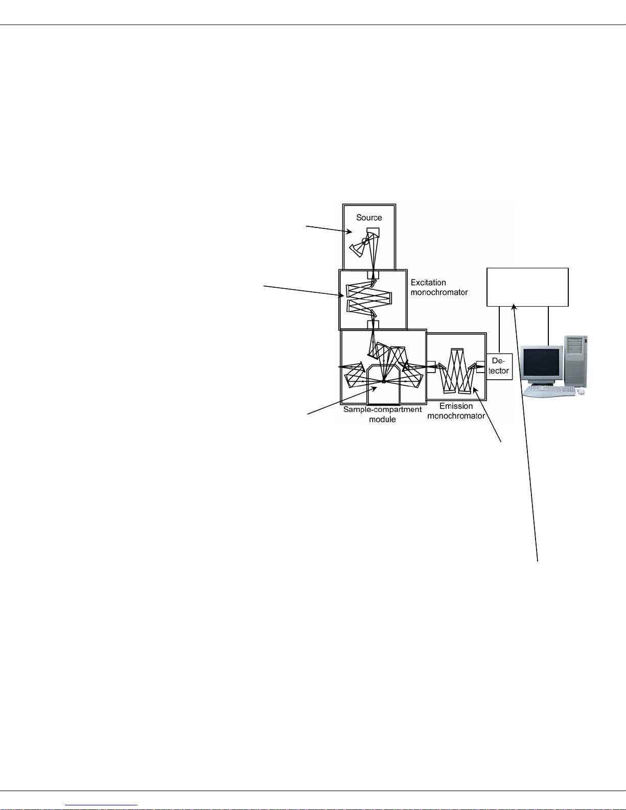
General operation
All Fluorolog®-3 spectrofluorometers have common features:
a A source of radiation
produces photons.
b The beam of light is
filtered by an
excitation
monochromator that
allows a single
wavelength of light to
reach the sample.
Controller
(SpectrAcq)
c In the sample
compartment, the
sample responds to the
incoming radiation.
d The resulting radiation is filtered by an emission monochromator that feeds
the signal to a photomultiplier detector.
e By stepping either or both monochromators through a wavelength region,
and recording the variation in intensity as a function of wavelength, a
spectrum is produced.
f The spectrofluorometer components (monochromators, sample-
compartment module, accessories) are connected to a controller (the
“SpectrAcq”), which, in turn, transfers information to and from the host
computer. The host computer may be attached to a printer or plotter.
2-1

Fluorolog-3 v. 3.2 (2 May 2008) System Description
Basic components
Monochromators
The Fluorolog®-3 comes equipped with either a single- or double-grating monochromator in
the excitation and emission positions. Double-grating monochromators offer a significant
increase in sensitivity, resolution and stray-light rejection.
Sample compartment
The standard sample-compartment module is a T-box, which provides efficient throughput
with a choice of standard right-angle emission collection or optional front-face emission
collection. The sample-compartment module comes equipped with a silicon photodiode
reference detector to monitor and compensate for variations in the xenon lamp output.
Detector
The standard detector offered on the Fluorolog®-3 is the R928P photomultiplier tube, which
provides sensitive spectral characterization in the UV through the visible.
Accessories
Fluorolog®-3 spectrofluorometers offer sampling accessories to increase flexibility, and
extend their applications to techniques such as polarization measurements or
phosphorescence lifetimes.
2-2
Fluorolog-3 v. 3.2 (2 May 2008) System Description
r
Configurations
The different configurations and various accessories available for the F luorolog®-3 system
allow you to customize a system specific for today’s needs, while the interchangeability of
the components and the inherent design enable the system to grow and change as new
applications arise.
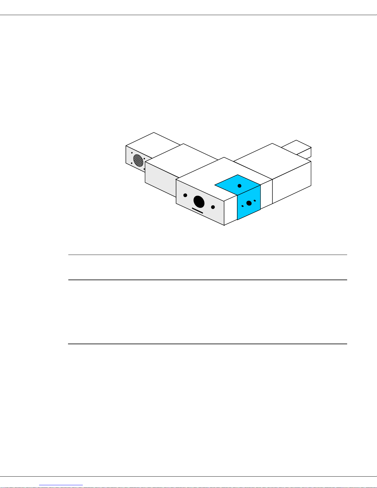
Standard systems
The standard Fluorolog®-3 systems include a single- or double-grating monochromator in
the excitation and emission paths in an “L” configuration.
Source
Excitation
spectrometer
Emission
spectrometer
Sample compa rtment
module
Detecto
Standard systems available:
Model
Source
Excitation
Monochromator
Sample
Compartment
Module
Emission
Monochromator
Detector
FL3-11 450-W Xe Single T-Box Single PMT
FL3-12 450-W Xe Single T-Box Double PMT
FL3-21 450-W Xe Double T-Box Single PMT
FL3-22 450-W Xe Double T-Box Double PMT
2-3
Fluorolog-3 v. 3.2 (2 May 2008) System Description
4
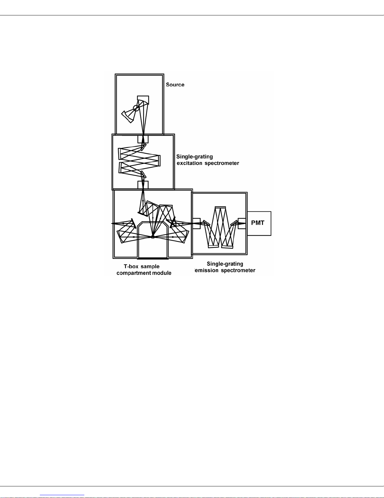
Fluorolog®-3 Model FL3-11
The Fluorolog®-3 Model FL3-11 is an economical system designed for routine fluorescence
measurements.
The standard model FL3-11 comes equipped with:
• 450-W light source
• single-grating excitation monochromator
• single-grating emission monochromator
• automatic slits
• room-temperature R928P detector
2-
Fluorolog-3 v. 3.2 (2 May 2008) System Description
5
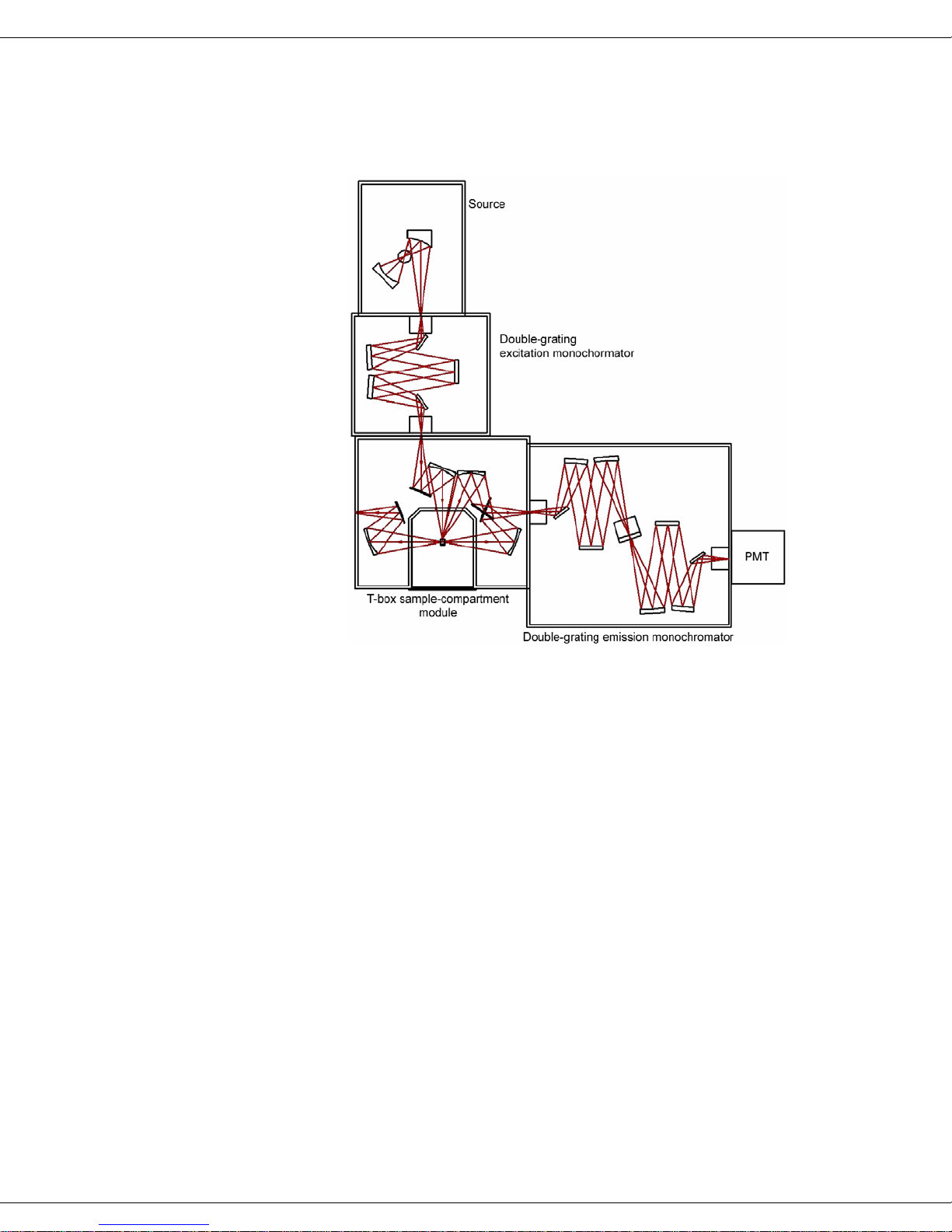
Fluorolog®-3 Model FL3-12
The Fluorolog®-3 model FL3-12 provides optimum performance for highly scattering
samples such as proteins, membranes, and solid samples.
Like the Model FL3-11, the Fluorolog®-3 Model FL3-12 has a single-grating excitation
monochromator; but the optimum performance of the Model FL3-12 is as a result of a
double-grating emission monochromator. Features of the Model FL3-12 are:
• 450-W light source
• single-grating excitation monochromator
• double-grating emission monochromator
• automatic slits
• room-temperature R928P detector
2-
Fluorolog-3 v. 3.2 (2 May 2008) System Description
6
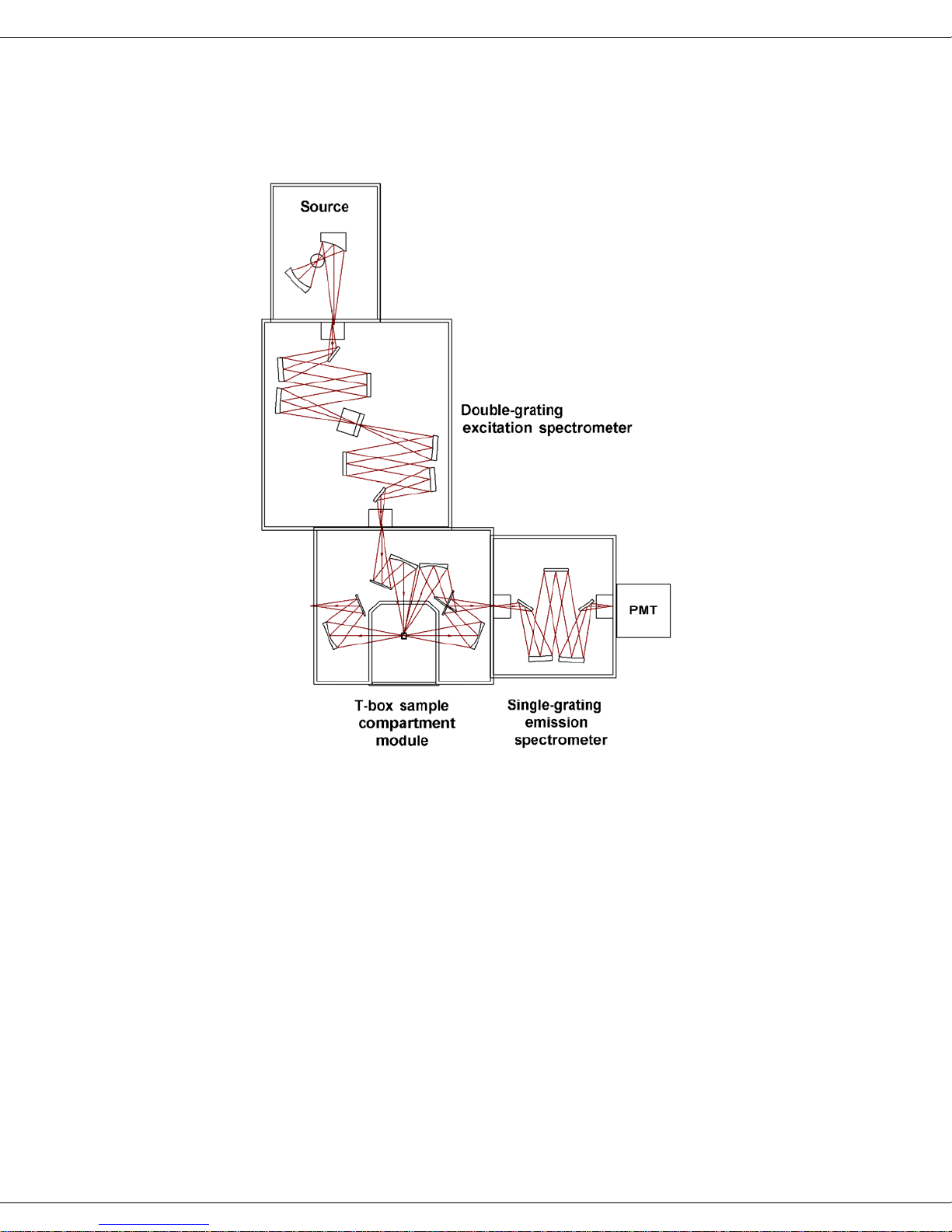
Fluorolog®-3 Model FL3-21
The Fluorolog®-3 model FL3-21 includes a double-grating monochromator at the excitation
position.
Features of the Model FL3-21 are:
• 450-W light source
• double-grating excitation monochromator
• single-grating emission monochromator
• automatic slits
• room-temperature R928P detector
2-
 Loading...