

horiba DS-72G Instruction Manual

Instruction Manual
COND METER ( DS-72G )


■ Preface
This manual describes the operation of the following instrument.
Brand (pet name): LAQUA
Series name: Benchtop pH/Water Quality Analyzer
Model: DS-72G
Model description: COND METER
Be sure to read this manual before using the product to ensure proper and safe
operation of the instrument. Also safely store the manual so it is readily possible
whenever necessary.
Product specifications and appearance, as well as the contents of this manual are
subject to change without notice.
● Warranty and responsibility
HORIBA Advanced Techno Co., Ltd. warrants that the Product shall be free from
defects in material and workmanship and agrees to repair or replace free of charge,
at option of HORIBA Advanced Techno Co., Ltd., any malfunctioned or damaged
Product attributable to responsibility of HORIBA Advanced Techno Co., Ltd. for a
period of one (1) year from the delivery unless otherwise agreed with a written
agreement. In any one of the following cases, none of the warranties set forth herein
shall be extended;
・ Any malfunction or damage attributable to improper operation
・ Any malfunction attributable to repair or modification by any person not authorized
by HORIBA Advanced Techno Co., Ltd.
・ Any malfunction or damage attributable to the use in an environment not specified
in this manual
・ Any malfunction or damage attributable to violation of the instructions in this
manual or operations in the manner not specified in this manual
・ Any malfunction or damage attributable to any cause or causes beyond the
reasonable control of HORIBA Advanced Techno Co., Ltd. such as natural
disasters
・ Any deterioration in appearance attributable to corrosion, rust, and so on
・ Replacement of consumables
HORIBA Advanced Techno Co., Ltd. SHALL NOT BE LIABLE FOR ANY DAMAGES
RESULTING FROM ANY MALFUNCTIONS OF THE PRODUCT, ANY ERASURE
OF DATA, OR ANY OTHER USES OF THE PRODUCT.
● Trademarks
Company names and brand names are either registered trademarks or trademarks
of the respective companies. (R), (TM) symbols may be omitted in this manual.
CODE:GZ0000260900H
January, 2017 2017 HORIBA Advanced Techno Co., Ltd.
I
■ Regulations
● EU regulations
● Conformable standards
This equipment conforms to the following standards:
EMC: EN61326-1
Safety: EN61010-1
RoHS: EN50581
Warning: This product is not intended for use in industrial environments. In an
industrial environment, electromagnetic environmental effects may
cause the incorrect performance of the product in which case the user
may be required to take adequate measures.
Regulations
Class B, Basic electromagnetic environment
9. Monitoring and control instruments
● Installation environment
This product is designed for the following environment.
- Overvoltage category II
- Pollution degree 2
● Information on disposal of electrical and electronic equipment and
disposal of batteries and accumulators
The crossed out wheeled bin symbol with underbar shown on the
product or accompanying documents indicates the product requires
appropriate treatment, collection and recycle for waste electrical and
electronic equipment (WEEE) under the Directive 2012/19/EU, and/or
waste batteries and accumulators under the Directive 2006/66/EC in
the European Union.
The symbol might be put with one of the chemical symbols below. In
this case, it satisfies the requirements of the Directive 2006/66/EC for
the object chemical.
This product should not be disposed of as unsorted household waste.
Your correct disposal of WEEE, waste batteries and accumulators will
contribute to reducing wasteful consumption of natural resources, and
protecting human health and the environment from potential negative
effects caused by hazardous substance in products.
Contact your supplier for information on applicable disposal methods.
II
● Authorised representative in EU
HORIBA UK Limited
2 Dalston Gardens, Stanmore, Middx HA7 1BQ, UK
Regulations
● FCC rules
Any changes or modifications not expressly approved by the party
responsible for compliance shall void the user's authority to operate the
equipment.
● Warning
This equipment has been tested and found to comply with the limits for
a Class A digital device, pursuant to part 15 of the FCC Rules. These
limits are designed to provide reasonable protection against harmful
interference when the equipment is operated in a commercial
environment. This equipment generates, uses, and can radiate radio
frequency energy and, if not installed and used in accordance with the
instruction manual, may cause harmful interference to radio
communications.
Operation of this equipment in a residential area is likely to cause
harmful interference in which case the user will be required to correct
the interference at his own expense.
Regulations
● Korea certification
●
● Taiwan battery recycling mark
III

● China regulation
ḽ䇦Ⲻᝅѿ
Meaning of Marking
䝬䞊䜽䛾ព㻌
ᵢḽ䇦䘸⭞൞ѣӰ≇ާૂള䬶⭫ಞ⭫ᆆӝθḽ䇦ѣཤⲺᮦ
ᆍ㺞⽰⧥ູؓᣚֵ⭞ᵕ䲆ⲺᒪᮦȾ(уᱥ㺞⽰ӝ䍞䠅ؓ䇷ᵕ䰪Ⱦ)
㾷䚫ᆾ䘏ѠӝᴿީⲺᆿޞૂֵ⭞⌞ᝅӁ亯θԄ䙖ᰛᔶခ㇍
䎭൞䘏Ѡᒪ䲆θуՐ㔏⧥ູ⊗ḉȽӰ։ૂ䍘ӝᑜᶛћ䠃ⲺᖧଃȾ
䈭у㾷䳅ᝅᓕᔹᵢ⭫ಞ⭫ᆆӝȾ
This marking is applied to electric and electronic products sold
in the People's Republic of China. The figure at the center of
the marking indicates the environmental protection use period
in years. (It does not indicate a product guarantee period.) It
guarantees that the product will not cause environment
pollution nor serious influence on human body and property
within the period of the indicated years which is count
ed from
the date of manufacture as far as the safety and usage
precautions for the product are observed. Do not throw away
ᮏ䝬䞊䜽䛿䚸୰⳹ேẸඹᅜ䛷㈍䛥䜜䜛㟁Ẽ㟁Ꮚ〇ရ䛻㐺⏝䛥
䜜䚸䝬䞊䜽䛾୰ኸ䛾ᩘᏐ䛿⎔ቃಖㆤ⏝ᮇ㝈䛾ᖺᩘ䜢ព䛧䜎䛩
䠄〇ရ䛾ရ㉁ಖドᮇ㛫䜢♧䛩䜒䛾䛷䛿䛒䜚䜎䛫䜣䠅䚹䛣䛾〇ရ䛻㛵
䛩䜛Ᏻ䜔⏝ୖ䛾ὀព䜢䛚Ᏺ䜚㡬䛟㝈䜚䚸〇㐀᪥䛛䜙㉳⟬䛩䜛䛣
䛾ᖺ㝈ෆ䛷䛿䚸⎔ቃởᰁ䜔ேయ䜔㈈⏘䛻῝้䛺ᙳ㡪䜢ཬ䜌䛩䛣䛸
䛿䛒䜚䜎䛫䜣䚹ᮏ〇ရ䜢䜏䛰䜚䛻ᗫᲠ䛧䛺䛔䛷䛟䛰䛥䛔䚹
Regulations
this product without any good reason.
IV
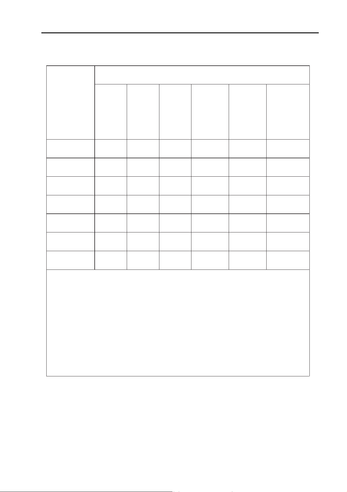
Regulations
ӝ
ѣᴿᇩ⢟䍞Ⲻ〦䠅
Na
me and amount of hazardous substance used in a product
䜞Ԭ〦
Unit name
ᴿᇩ⢟䍞
䫻
Lead
(Pb)
⊔
Mer
cury
(Hg)
䭿
Cad-
mium㻌
(Cd)
ޣԭ䬢
Hexavalent
chrom-
ium㻌
(Cr (VI))
ཐ⓪㚊㤥
Poly
bromo-
biphenyl
(PBB)
ཐ⓪ӂ㤥䟐
Poly
bromo-
diphenyl
ether
(PBDE)
ᵢ։
ۑۑ ۑ ۑ ۑ
⭫⊖
Battery
ۑۑ ۑ ۑ ۑ
AC䘸䞃ಞ
*1
ۑۑ ۑ ۑ ۑ
⭫㔼
Cable
ۑۑ ۑ ۑ ۑ
᭥
*2
ۑۑۑ ۑ ۑ ۑ
ᢉদᵰ
Printer
*2
ۑۑ ۑ ۑ ۑ
⭫ᶷ
*2
ۑ ۑ ۑ ۑ
ᵢ㺞ṲדᦤSJ/T 11364Ⲻ㿺ᇐ㕌Ⱦ
This form is prepared in accordance with SJ/T 11364.
ۑ: 㺞⽰䈛ᴿᇩ⢟䍞൞䈛䜞Ԭᡶᴿൽ䍞ᶆᯏѣⲺ䠅ൽ൞ GB/T 26572 㿺ᇐⲺ䲆䠅㾷
≸ԛсȾ
Denotes that the amount of the hazardous substance contained in all of the
homogeneous materials used in the component is below the limit on the
acceptable amount stipulated in the GB/T 26572.
h: 㺞⽰䈛ᴿᇩ⢟䍞㠩ቇ൞䈛䜞ԬⲺḆжൽ䍞ᶆᯏѣⲺ䠅䎻࠰GB/T 26572 㿺ᇐⲺ
䲆䠅㾷≸Ⱦ
Denotes that the amount of the hazardous substance contained in any of the
homogeneous materials used in the component is above the limit on the
*1: ᵢ䜞ԬⲺ⧥ֵؓ⭞ᵕ䲆Ѱ10ᒪȾ㻌 The environmental protection use period
of this product is 10 years.
*2:
䘿䞃Ԭ
Optional products
Hazardous substance
Main unit
AC adapter
Stand
Electrode
acceptable amount stipulated in the GB/T 26572.
V
For Your Safety
■ For Your Safety
● Hazard classification and warning symbols
Warning messages are described in the following manner. Read the
messages and follow the instructions carefully.
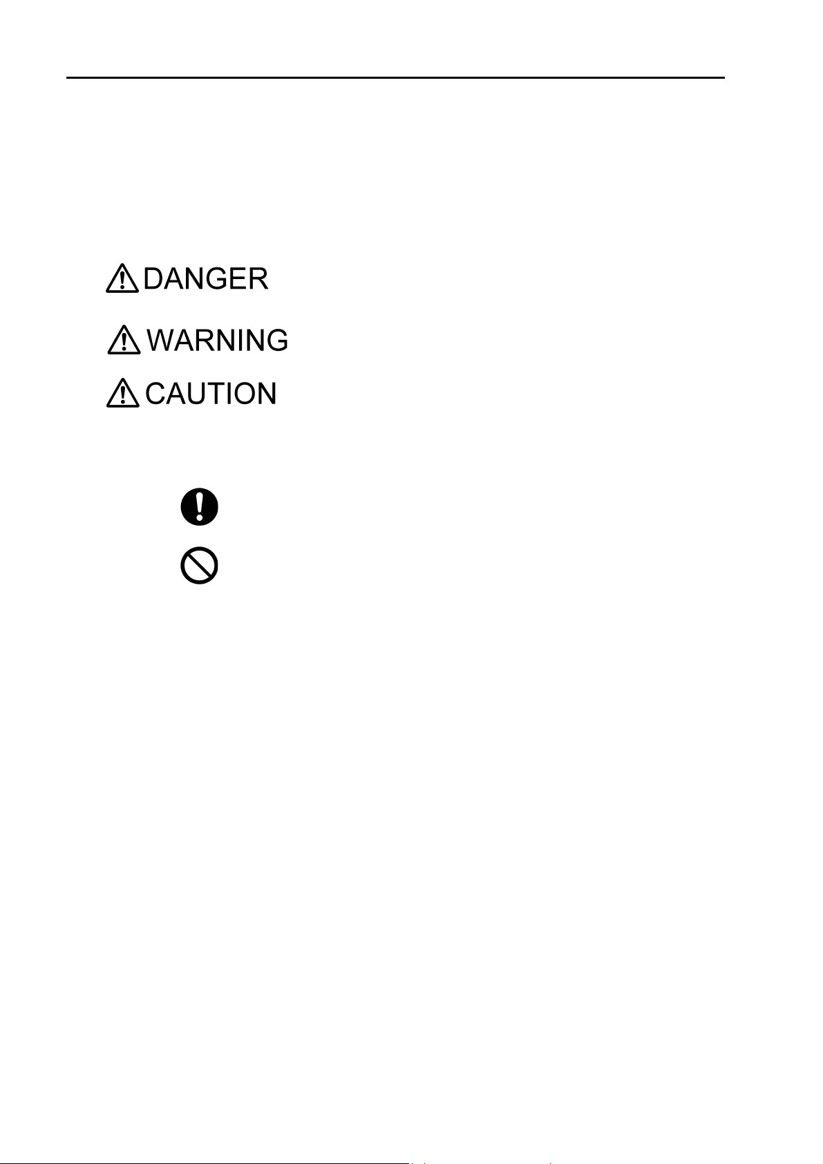
● Hazard classification
This indicates an imminently hazardous situation which, if not
avoided, will result in death or serious injury. This signal word
is to be limited to the most extreme situations.
This indicates a potentially hazardous situation which, if not
avoided, could result in death or serious injury.
This indicates a potentially hazardous situation which, if not
avoided, may result in minor or moderate injury. It may also be
used to alert against unsafe practices.
● Warning symbols
Description of what should be done, or what should be followed
Description of what should never be done, or what is prohibited
Safety Operation
● [DEU] Sicherheitsinformation
Lesen Sie vor der Verwendung des Produkts unbedingt diese Anleitung, um den ordnungsgemäßen und sicheren Betrieb des Produkts zu
gewährleisten. Bewahren Sie die Anleitung sicher auf, damit sie bei
Bedarf jederzeit zur Hand ist.
Die Inhalt dieser Anleitung können ohne Vorankündigung geändert
werden.
● Installationsumgebung
Dieses Produkt ist nicht zum Gebrauch in industriellen Umgebungen,
wie in EN61326-1 definiert, vorgesehen.
In einer industriellen Umgebung können die elektromagnetischen Störungen eventuell zu Produktfehlfunktionen führen. Um dieses Produkt
unter solchen Umständen verwenden zu können, muss der Benutzer
ggf. angemessene Maßnahmen ergreifen.
VI
Das Produkt ist gemäß EN61010-1 für die folgende Umgebung vorgesehen.
●
Überspannungskategorie II
●
Verschmutzungsgrad 2

For Your Safety
● [FRA] Informations de sécurité
Veillez à lire le présent manuel avant d’utiliser le produit de manière à
garantir son utilisation correcte et sûre. De même, rangez le manuel
dans un lieu sûr de manière à pouvoir vous y reporter lorsque cela est
nécessaire.
Le contenu du présent manuel peut être modifié sans notification préalable.
● Environnement d’installation
Ce produit n'est pas destinés à une utilisation dans des environnements industriels, tels que définis dans la norme EN61326-1.
Dans un environnement industriel, les interférences électromagnétiques peuvent entraîner un dysfonctionnement du produit. Pour utiliser
le produit dans ce type d’environnements, l’utilisateur peut avoir à
prendre des mesures appropriées.
Le produit est conçu pour l’environnement suivant, tel que défini dans
la norme EN61010-1.
●
Catégorie de surtension II
●
Degré de pollution 2
● [ITA] Informazioni sulla sicurezza
Leggere attentamente questo manuale prima di utilizzare il prodotto al
fine di utilizzarlo in modo sicuro e adeguato. Inoltre, conservare in un
luogo sicuro il manuale per poterlo consultare se necessario.
Le contenuti di questo manuale sono soggetti a modifiche senza preavviso.
● Ambiente di installazione
Questo prodotto non è stati progettati per essere utilizzati in ambienti
industriali, secondo la norma EN61326-1.
In un ambiente industriale, le interferenze elettromagnetiche potrebbero causare un malfunzionamento del prodotto. Per utilizzare il prodotto in tali ambienti, all'utente potrebbe essere richiesto di adottare le
contromisure necessarie.
Il prodotto è designato per il seguente ambiente, definito nello standard
EN61010-1.
●
Categoria di sovratensione II
●
Livello di inquinamento 2
VII

For Your Safety
● [SWE] Säkerhetsinformation
Se till att du läser denna handbok innan du börjar använda produkten
för en korrekt och säker användning av den. Spara sedan handboken
på en säker och lättåtkomlig plats så att du kan konsultera den när så
behövs.
Innehållet i denna handbok kan komma att ändras utan föregående
meddelande därom.
● Installationsmiljö
Detta produkten är ej avsedda för användning i industriella miljöer
enligt riktlinjerna i EN61326-1.
Om den används i industrimiljöer kan de elektromagnetiska störningarna orsaka tekniska fel hos produkten. Om produkten ska användas i
sådana miljöer kan användaren behöva vidta lämpliga åtgärder för att
lösa dessa problem.
Produkten är utformad för användning i följande miljöer, i enlighet med
SS-EN 61010-1.
●
Överspänningskategori II
●
Föroreningsgrad 2
● [SPA] Información de seguridad
Asegúrese de leer este manual antes de utilizar el producto para
garantizar un uso correcto y seguro del mismo. Asimismo, guarde de
forma segura el manual para que esté disponible siempre que sea
necesario.
El contenido de este manual están sujetos a cambios sin previo aviso.
● Entorno de instalación
Este producto está diseñado para su uso en entornos industriales, tal y
como se define en EN61326-1.
En un entorno industrial, las interferencias electromagnéticas pueden
provocar un funcionamiento incorrecto del producto. Para usar el producto en tales entornos, el usuario debe tomar las medidas adecuadas.
El producto se ha diseñado para el siguiente entorno, definido en
EN61010-1.
●
Categoría de sobretensión II
●
Nivel de contaminación 2
VIII

For Your Safety
● [POL] Informacje dotyczące bezpieczeństwa
Przed przystąpieniem do użytkowania tego produktu należy dokładnie
zapoznać się z niniejszą instrukcją, aby zapewniona była prawidłowa i
bezpieczna eksploatacja produktu. Instrukcję przechowywać w bezpiecznym miejscu, aby w razie potrzeby była zawsze dostępna.
Treść niniejszej instrukcji może ulec zmianie bez wcześniejszego
powiadomienia.
● Środowisko instalacji
Ten produkt nie są przeznaczone do użytkowania w środowisku przemysłowym, zgodnie z definicją określoną w normie EN61326-1.
W środowisku przemysłowym zakłócenia elektromagnetyczne mogą
powodować nieprawidłowe działanie produktów. Możliwe, że aby użytkować produkt w takich środowiskach, użytkownik będzie musiał podjąć stosowne środki zaradcze.
Produkt jest przeznaczony do użycia w poniższym środowisku zdefiniowanym w normie EN61010-1.
●
Kategoria przepięciowa II
●
Stopień zanieczyszczenia 2
● [NLD] Veiligheidsinformatie
Lees deze handleiding voordat u dit product gebruikt zodat u het op de
juiste manier en veilig kunt gebruiken. Bewaar de handleiding goed
zodat u hem wanneer nodig kunt raadplegen.
De inhoud van deze handleiding kunnen zonder voorafgaande kennisgeving worden gewijzigd.
● Installatieomgeving
Dit product is niet bedoeld voor gebruik in een industriële omgeving
zoals gedefinieerd in EN 61326-1.
In een industriële omgeving kan de elektromagnetische interferentie de
werking van dit product storen. Voor gebruik van het product in een dergelijke omgeving moet de gebruiker mogelijk maatregelen treffen om
de storing te verhelpen.
Het product is ontworpen voor de volgende omgeving, gedefinieerd in
EN 61010-1.
●
Overspanningscategorie II
●
Vervuilingsgraad 2
IX

● [JPN] 安全情報
ご使用になる前に、本書を必ずお読みください。お読みになった後は
必要なときにすぐに取り出せるように大切に保管してください。
本書に記載されている内容は予告なく変更される場合があります。あ
らかじめご了承ください。
● 設置環境
本製品は、EN61326-1 で定義される工業環境で使用することを想定し
た製品ではありません。
工業環境においては、電磁妨害の影響を受ける可能性があり、その場
合には使用者が適切な対策を講ずることが必要となることがありま
す。
本製品は、EN61010-1 で定義される以下の環境用に設計されています。
●
過電圧カテゴリー II
●
汚染度 2
For Your Safety
X
● Safety Precautions
WARNING
CAUTION
This section provides precautions to enable you to use the product
safely and correctly and to prevent injury and damage. The terms of
DANGER, WARNING, and CAUTION indicate the degree of imminency
and hazardous situation. Read the precautions carefully as it contains
important safety messages.
Do not use an unspecified AC adapter.
Otherwise, it may heat up or be ignited resulting in a fire or an accident.
Do not disassemble or modify the meter.
Otherwise, it may heat up or be ignited resulting in a fire or an accident.
Fire
• For your safety, make sure to unplug the power plug from the electrical outlet
when not in use.
• Clear dust on the power plug periodically (a few times a year).
If the power supply cord is left plugging into the electrical outlet for a long period of
time, electrical tracking may occur due to dust and moisture, and it may result in an
ignition or a fire.
For Your Safety
Fire or electric shock
• Do not bundle the power supply cord during use.
• Do not damage the power supply cord nor apply an excessive load to it, such as
bending and stretching it repeatedly, putting a heavy thing on it.
• If it cannot be plugged into an electrical outlet firmly, stop use of the power
supply cord.
If may result in overheating, a fire, an electrical shock, or breakdown.
Harmful chemicals
Some ion electrodes are used with hazardous standard solutions. Handle them
with care.
If the internal solution comes in contact with the skin, wash it off immediately. If it
gets into eyes, flush with plenty of water and then consult a doctor.
Harmful chemicals
The internal solution of an electrode is highly concentrated potassium chloride
(3.33 mol/L KCl).
If the internal solution comes in contact with the skin, wash it off immediately. If it
gets into eyes, flush with plenty of water and then consult a doctor.
Broken glass
Broken glass may cause injury.
The outer tube and tip of an electrode are made of glass.
Handle them with care.
XI
For Your Safety
CAUTION
Do not use the cable of serial communication, USB, or AC adapter under wet or
humid conditions.
Otherwise, it may cause a fire, electric shock, or breakage.
XII

Product Handling Information
■ Product Handling Information
● Operational precautions
●
Only use the product including accessories for their intended
purpose.
●
Do not drop, crash, or give any physical impact on the instrument.
●
Do not immerse the instrument into alcohol, organic solvent, strong
acid, strong alkaline, or the like. The instrument body contains ABS
resin, acrylic resin, and some rubber parts.
●
If the instrument is dropped into water or gets wet, wipe it using soft
cloth. Do not heat to dry it with a hair-dryer (or the like).
●
Use fingers to press the operation keys or the touch panel.
Do not use a hard object like a metal stick or rod.
●
Be careful not to let water into the instruction inside.
The instrument is not water-proof.
●
To disconnect an electrode or interface cable, hold the connector and
pull it off. If you pull at the cable, it may cause a breakage.
●
The touch panel is capacitance-type. Make sure to turn OFF the
power before cleaning the panel. If you wipe it with the power ON, it
may cause instrument malfunction.
●
RS-232C or USB communication between the instrument and a personal computer may fail because of environmental conditions, such
as (radio/electromagnetic) noise.
●
Make sure to use the provided power supply cable to power this
product.
● Environmental conditions for use and storage
●
Temperature: 0C to 45C
●
Humidity: under 80% in relative humidity and free from
condensation
Avoid the following conditions:
●
Dusty environment
●
Strong vibration
●
Direct sunlight
●
Corrosive gas environment
●
Close to an air-conditioner
●
Direct wind
● Transportation
When transporting the instrument, repackage it in the original package
box. Otherwise, it may cause instrument breakage.
● Disposal
Standard solution used for the calibration must be under neutralized
before the disposal. As for the disposal of the meter, treat it as an
industrial waste.
XIII

Manual Information
HINT!
■ Manual Information
● Description in this manual
This interprets the necessary points for correct operation and notifies
the important points for handling the product.
This indicates the part where to refer for information.
This indicates reference information.
● Original language
This is the English translation of an original Japanese document.
Manual Information
XIV

Contents
■ Preface ....................................................................................................... I
■ Regulations .............................................................................................. II
■ For Your Safety ....................................................................................... VI
■ Product Handling Information ............................................................. XIII
■ Manual Information .............................................................................. XIV
Chapter 1 Overview ................................................................................... 1
1.1 Description of Each Part ........................................................................ 1
1.1.1 Rear ................................................................................................ 1
1.1.2 Display ............................................................................................ 1
1.1.3 Left Side .......................................................................................... 2
1.1.4 Right Side ....................................................................................... 2
1.1.5 Accessories .................................................................................... 3
1.1.6 Identification of Manufacturing Date ............................................... 4
1.1.7 Operation Keys ............................................................................... 4
1.1.8 Icons (Icon Bar) .............................................................................. 5
1.1.9 Status Icons .................................................................................... 6
1.1.10 Meas Screen ................................................................................. 7
1.2 Basic Operation of Touch-Panel and Touch-Key ................................ 8
1.3 Function and Operation of the Meas Screen ....................................... 9
1.4 Assembling the Electrode Stand ........................................................ 11
1.5 Connecting the Electrode .................................................................... 12
1.5.1 Electrode Connector ..................................................................... 12
1.5.2 Temperature Connector ................................................................ 12
1.6 Connecting the Power Source ............................................................ 13
1.7 Connectin
1.8 Connecting the Personal Computer ................................................... 14
1.9 Turn ON the Power ............................................................................... 15
g the Printer ......................................................................... 13
Chapter 2 Before Measurement (Meter SET) ......................................... 16
2.1 Meter SET Screen ................................................................................. 16
2.2 Auto Hold Setting ................................................................................. 16
2.3 Custom Setting ..................................................................................... 17
2.4 Sample Name Setting ........................................................................... 18
2.5 Interval Memory Setting ....................................................................... 19
2.6 USB Memory Setting ............................................................................ 20
2.7 Printer Setting ....................................................................................... 22
2.8 Screen Settings .................................................................................... 24
2.9 Sound Setting ....................................................................................... 26
2.10 Language Setting ............................................................................... 27
2.11 Security Setting .................................................................................. 27
2.12 User Entry/Info Change/Delete .......................................................... 29
2.13 Date Setting ......................................................................................... 31
2.14 Analog Output Adjustment ................................................................ 32
2.15 Temperature Sensor Calibration ....................................................... 33
XV

Contents
2.16 Resetting to Factory Defaults ............................................................ 34
Chapter 3 COND (Conductivity) Measurement ..................................... 35
3.1 COND Calibration ................................................................................. 35
3.1.1 Automatic Calibration Setting ........................................................ 35
3.1.2 Calibration of Standard Solution ................................................... 36
3.2 COND Measurement Setting ................................................................ 39
3.2.1 Cell Constant Setting .................................................................... 39
3.2.2 COND Measurement Unit Setting ................................................. 40
3.2.3 Temperature Setting ..................................................................... 41
3.2.4 Temperature Conversion Function Setting ................................... 42
3.2.5 Alarm Setting ................................................................................ 43
3.2.6 Electrode Model Setting ................................................................ 45
3.2.7 Electrode Lot No. Setting .............................................................. 46
3.3 COND Measurement ............................................................................. 47
Chapter 4 SAL (Salinity) Measurement ................................................. 48
4.1 Measurement Target Selection ............................................................ 48
4.2 SAL Calibration Setting ........................................................................ 49
4.3 SAL Measurement Setting ................................................................... 50
4.4 SAL Measurement Unit Setting ........................................................... 50
4.5 Temperature Setting ............................................................................. 50
4.6 Alarm Setting ........................................................................................ 51
4.6.1 Input Upper or Lower Limit Values ................................................ 51
4.7 Electrode Model Setting ....................................................................... 52
4.8 SAL Measurement ................................................................................ 52
Chapter 5 Resist (Resistivity) Measurement ......................................... 53
5.1 Resist Measurement Setting ................................................................ 53
5.2 Resist Measurement Unit Setting ........................................................ 53
5.3 Temperature Setting ............................................................................. 53
5.4 Alarm Setting ........................................................................................ 54
5.4.1 Input Upper or Lower Limit Values ................................................ 54
5.5 Electrode Model Setting ....................................................................... 55
5.6 Resist Measurement ............................................................................. 55
Chapter 6 TDS (Total Dissolved Solids) Measurement ........................ 56
6.1 TDS Measurement Setting ................................................................... 56
6.2 TDS Measurement Mode Setting ......................................................... 56
6.2.1 Input TDS Linear Value when Selecting LINEAR ......................... 57
6.3 Temperature Setting ............................................................................. 57
6.4 Alarm Setting ........................................................................................ 57
6.4.1 Input Upper or Lower Limit Values ................................................ 58
6.5 Electrode Model Setting ....................................................................... 58
XVI

Contents
6.6 TDS Measurement ................................................................................ 59
Chapter 7 Application Mode ................................................................... 60
7.1 Pharmacopeia Mode ............................................................................. 60
7.1.1 Shift to Pharmacopeia Mode ........................................................ 61
7.1.2 Measured by USP (Stage 1) ......................................................... 61
7.1.3 Measured by USP (Stage 2) ......................................................... 62
7.1.4 Measured by EP ........................................................................... 63
7.1.5 Measured by JP (OFF-LINE) ........................................................ 64
7.1.6 Measured by JP (0mL-10mL (in container)) ................................. 65
7.1.7 Measured by JP (10mL- (in container)) ........................................ 66
7.1.8 Measured by PPRC (CP) (Stage 1) .............................................. 67
7.1.9 Measured by PPRC (CP) (Stage 2) .............................................. 68
7.1.10 Temperature and Conductivity Requirements ............................ 69
Chapter 8 Periodic Inspection Mode ...................................................... 70
8.1 COND Periodic Inspection Mode Setting ........................................... 70
8.1.1 Pharmacopoeia Mode ................................................................... 70
8.1.2 COND Checker (X-52) Mode ........................................................ 72
8.2 Comment Input ..................................................................................... 73
Chapter 9 Data ......................................................................................... 74
9.1 Measured data_All ................................................................................ 74
9.2 Deleting Saved Data ............................................................................. 74
9.3 Measured data_latest50 ....................................................................... 75
9.4 Measured data_search ......................................................................... 75
9.5 Copy all meas. Data ............................................................................. 76
9.6 Delete all meas. Data ............................................................................ 76
Chapter 10 Specifications ....................................................................... 77
10.1 Model Information .............................................................................. 77
10.2 Measuring Object ............................................................................... 77
10.3 Default Settings .................................................................................. 79
10.3.1 Meter Default Settings ................................................................ 79
10.3.2 Measurement Condition Default Settings
(Can Be Set per Operator) ............................................................ 80
10.4 Options ................................................................................................ 82
XVII

Chapter 1 Overview
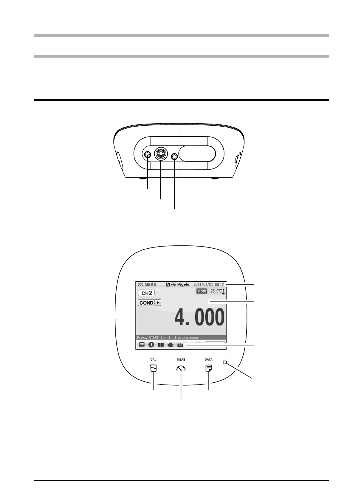
CH2 reference electrode
CH2 measurement electrode
CH2 for temperature electrode
CAL key
POWER key
MEAS key
DATA key
Icon bar
Status bar
Touch panel
This chapter describes functions and basic operations of the instrument.
1.1 Description of Each Part
1.1.1 Rear
1.1.2 Display
1
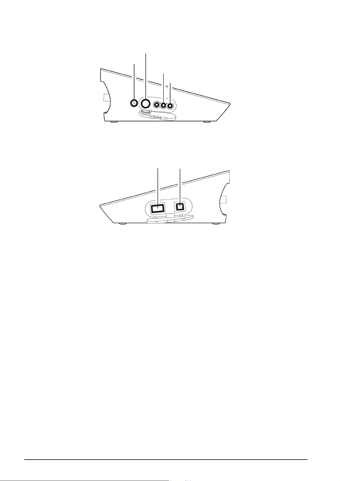
1.1.3 Left Side
AC adapter connector
Serial communication connector (RS-232C)
Analog output connector 2 (CH2 data)
Analog output connector 3 (Alarm)
Connector for
Connector for
USB communication
with a personal computer
USB memory
1.1.4 Right Side
2
1.1.5 Accessories
(mm)
(mm)
Name Function
AC adapter* Used to power the instrument.
Electrode stand Used to move and set electrodes during measurement.
Rubber cover Protects the instrument side surfaces.
Instruction manual Instructs the usage of the instrument.
Quick manual Instructs the operations of calibration and measurement.
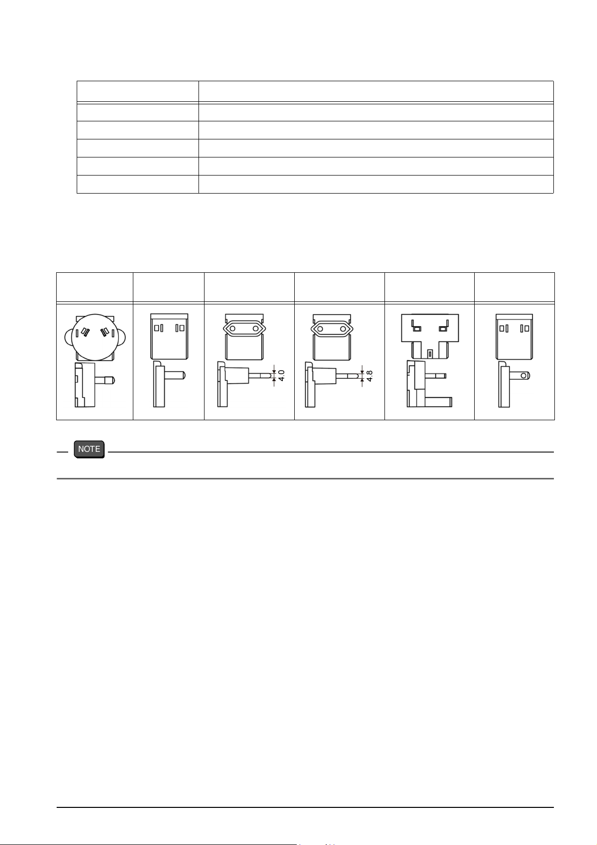
*: The AC adapter includes 6 plug adapters.
Referring to the following table, attach the appropriate plug adapter to the AC
adapter depending on the country to be used.
① Australia ② China ③ Europe ④ Korea ⑤ U.K., Singapore
Clock battery (CR-2032) is put into the battery cover at the instrument bottom.
⑥ USA, Canada,
Ta iw a n
3
1.1.6 Identification of Manufacturing Date
Manufacturing date can be identified from MFG No. described in the ID label on the
backside of the instrument.
Third number from the left in the MFG No. indicates manufacturing year.
Forth alphabet from the left in the MFG No. indicates manufacturing month.
The alphabet is assigned to month according to the table below.
Ex.: ID: AA6A0000 means the device manufactured in 2016 January.
JAN FEB MAR APR MAY JUN JUL AUG SEP OCT NOV DEC
AB C DE FGH J K L M
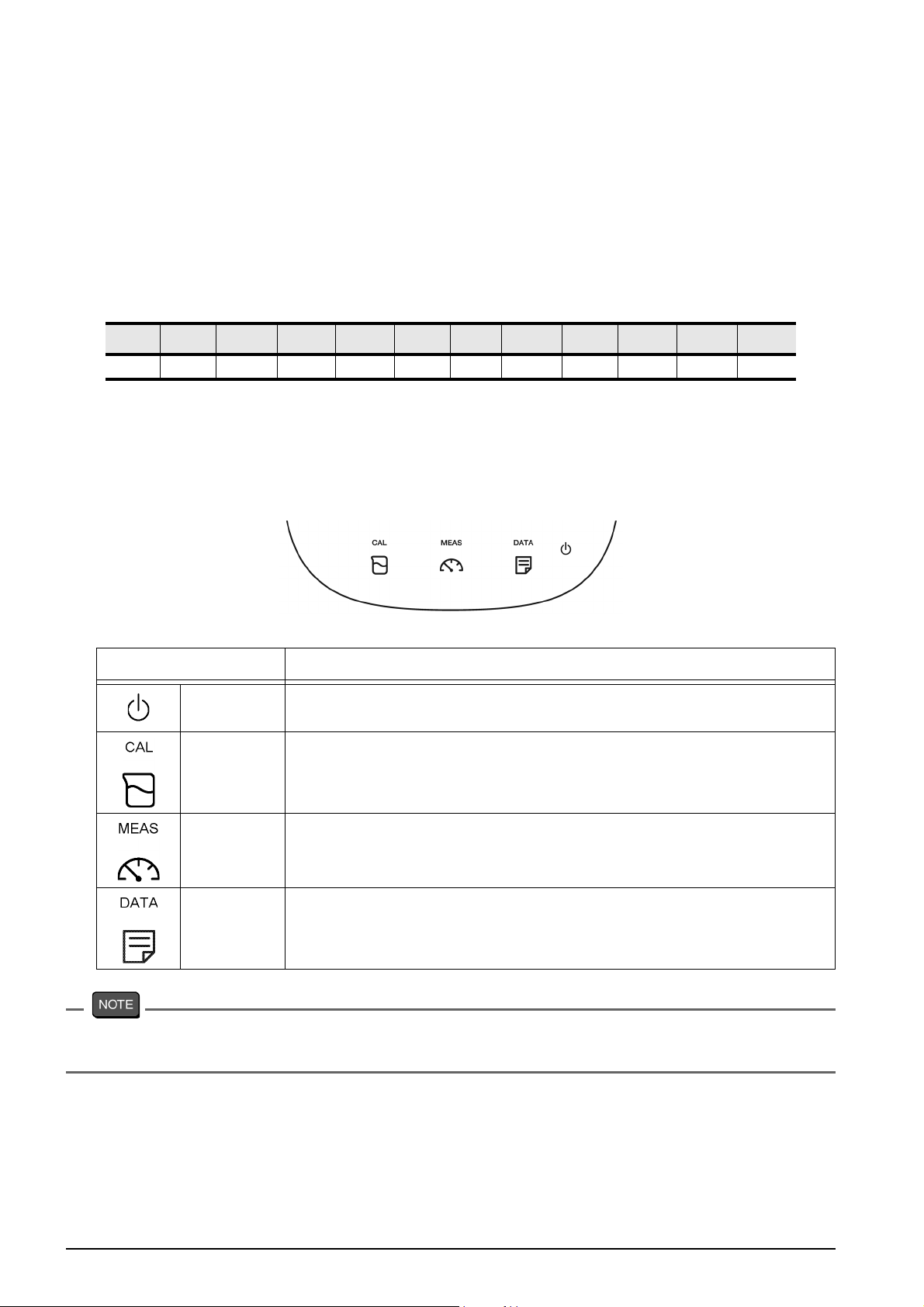
1.1.7 Operation Keys
Operation key Function
POWER
CAL Displays the calibration screen (CAL screen).
MEAS Displays the measurement screen (MEAS screen).
DATA Displays the data screen (DATA screen).
The POWER key does not work for 10 seconds after the AC adapter is connected.
Wait for a while after connecting AC adapter.
Turns ON or OFF the power.
(Press and hold for 2 seconds or more.)
4
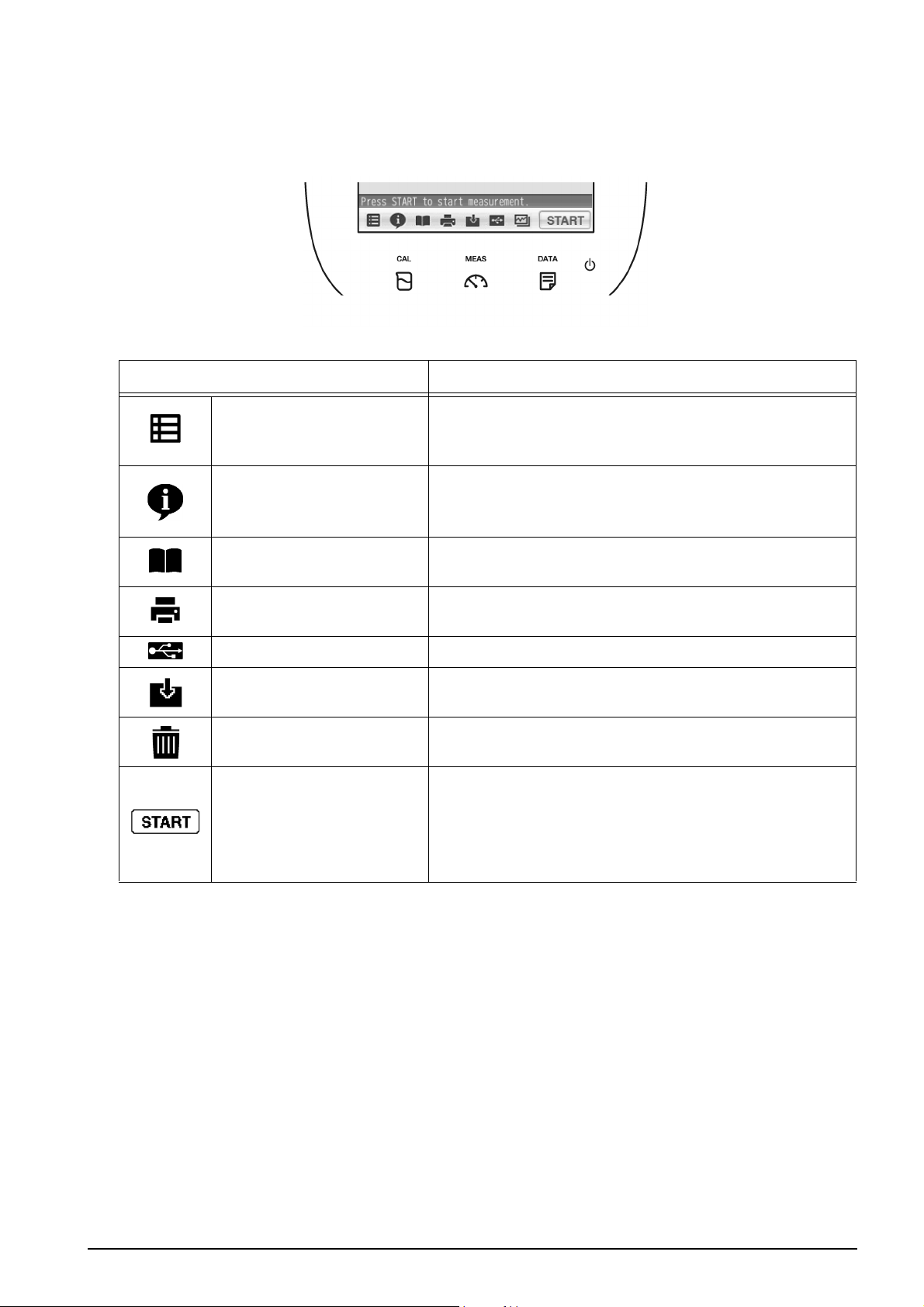
1.1.8 Icons (Icon Bar)
The icons displayed on the bottom of the touch panel allow you to set up the instrument,
check calibration information, and print out and save data.
Icon Function
Used to perform measurement, display the Meter
Menu
Information
SET screen, and switch to the inspection and
application modes.
Used to check calibration information on the MEAS
or CAL screen, and application information on the
Meter SET screen.
User's guide
Printer
Save in USB Used to save measured data into a USB memory.
Save data
Trash box
Operation
Used to check operation instructions and
information about measurement and maintenance.
Used to print out measurement or calibration
values or saved data when a printer is connected.
Used to save measurement values displayed on
the screen into the instrument.
Used to delete calibration data or the data saved in
the instrument.
Used to start and stop the operations of
measurement and calibration, and to change to the
instantaneous value display.
The icon label depends on the corresponding
operation.
5
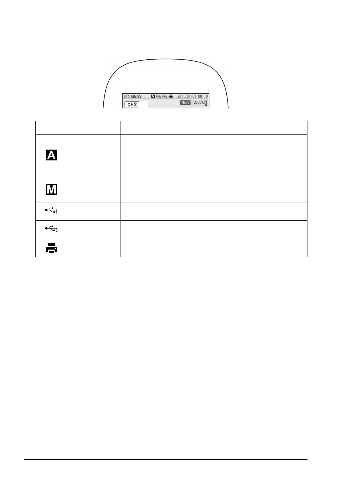
1.1.9 Status Icons
The icons displayed on the top of the touch panel show information on the instrument.
Status icon Function
Shows that the automatic hold function is ON, and that the
end point is determined automatically according to input
Auto hold
Manual hold
signals from the electrode based on the pre-selected stability
criterion of measurement values.
Refer to "2.2 Auto Hold Setting" (P.16).
Shows that the manual hold function is ON, and that the end
point is determined manually.
Refer to "2.2 Auto Hold Setting" (P.16).
USB1
USB2
Printer
*1: These icons appear when a USB cable is connected, but it does not always mean that
the communication is conducted.
*1
*1
Shows that the instrument is connected with a personal
computer via a USB cable.
Shows that the instrument is connected with a USB data
storage media.
Shows that the instrument is connected with a printer with a
dedicated printer cable.
6
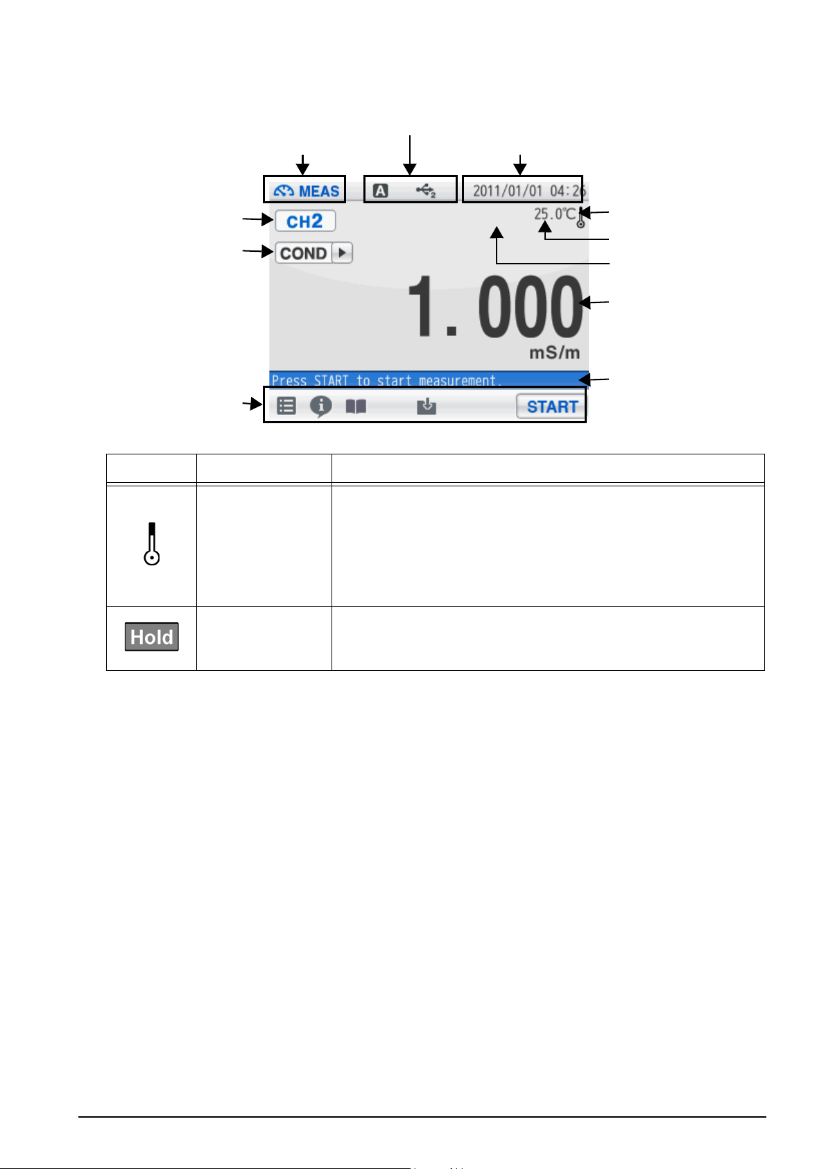
1.1.10 Meas Screen
Temperature
HOLD indicator
Channel
Icon
Measurement mode
Status
Date and time
Measurement item
Temperature
compensation
electrode
connection
indicator
Measurement values
Measurement
operation
information
Indicator Name Description
Temperature
compensation
electrode
connection
indicator
HOLD indicator
Displayed: A temperature compensation electrode
is connected.
The displayed temperature is the
electrode temperature (ATC).
Not displayed: The displayed temperature is preset
value (MTC).
Not displayed: An instantaneous value is displayed.
Blinking: In-process for HOLD
Lighting up: HOLD completed.
7
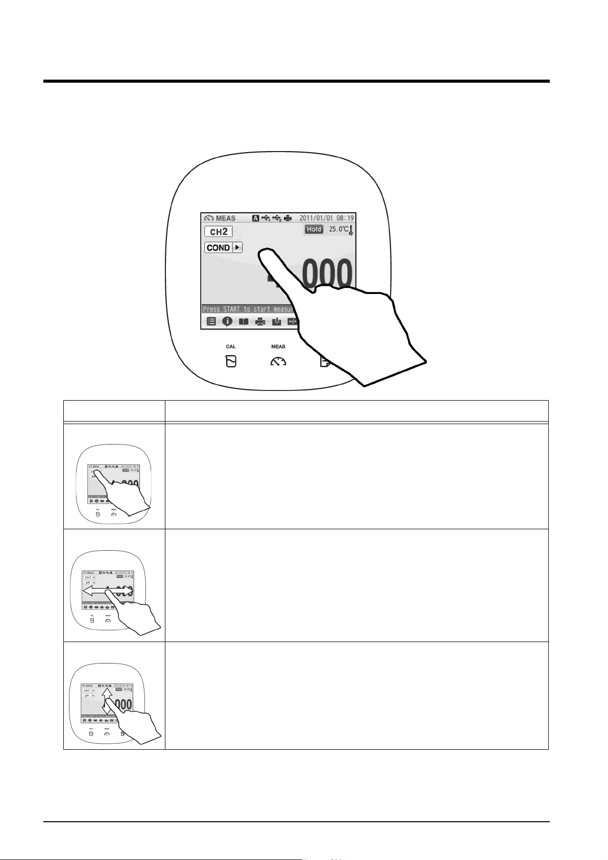
1.2 Basic Operation of Touch-Panel and Touch-Key
The instrument has touch panel and keys and you can operate it by touching the screen.
The 3 basic operations of Tap, Flick, and Drag allow you to operate the instrument
intuitively. This section describes the basic operations.
Operation Description
Tap Tap on the screen lightly once with a finger.
Tap a menu item or icon to select it or change settings.
Flick Touch and flick on the screen with a finger.
Used to switch to the digital or graph display on the MEAS or CAL
screen.
Drag Keep a finger in contact with the screen and drag it on the screen.
Used to search a setting item, or measurement data on the DATA
screen. When a scroll bar is displayed on the right of the screen, you
can scroll the screen by this operation.
8
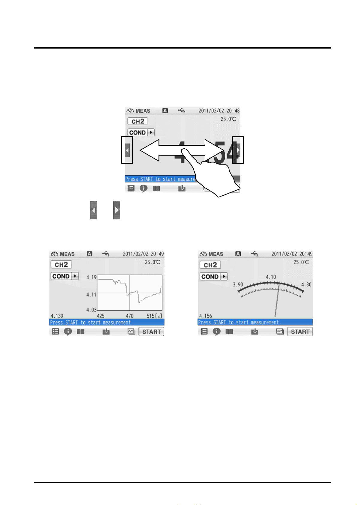
1.3 Function and Operation of the Meas Screen
The MEAS screen has three display methods to check variation and tendency of
measurement values.
You can shift the screen to the digital, graph or analog screen by flicking it.
Digital display
If arrows, like and , appear when you touch the screen, you can flick in the directions
to switch the screen display.
Graph display Analog display
9
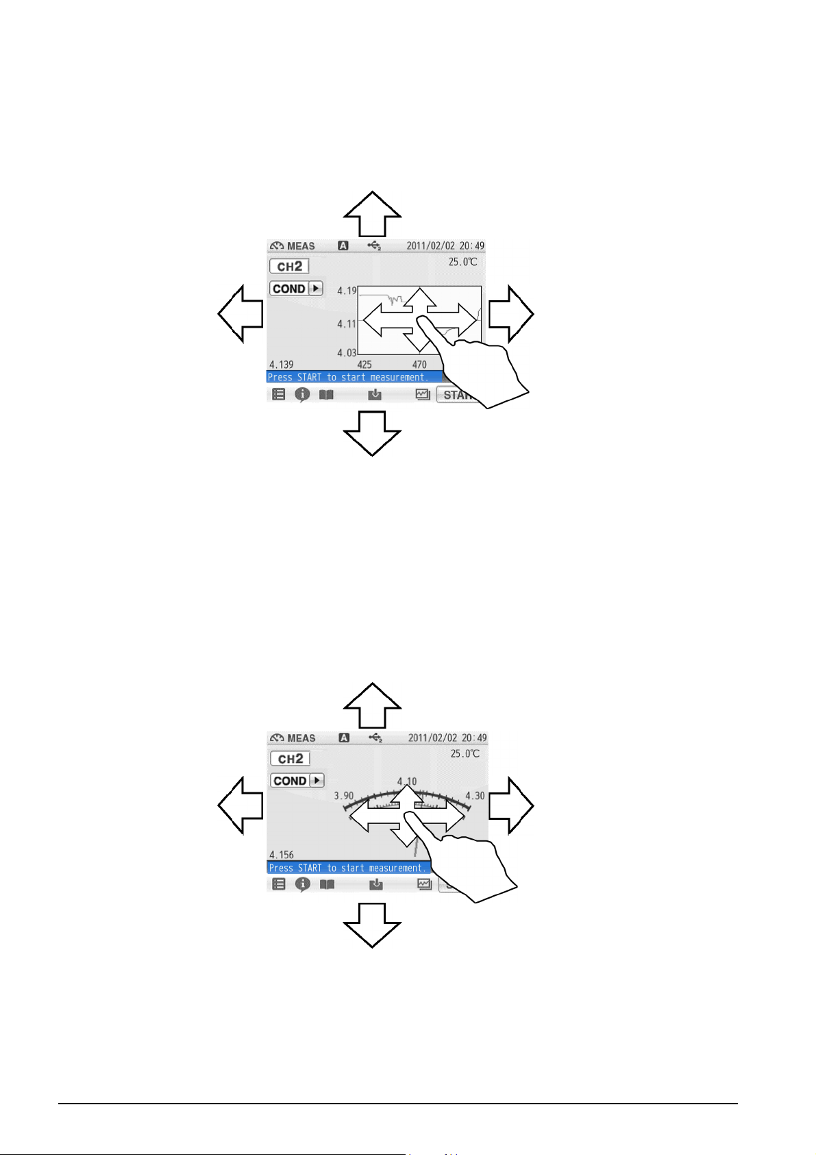
● Graph display
The vertical axis is zoomed in.
The displayed range narrows.
The vertical axis is zoomed in.
The displayed range narrows.
Displays the next or
the latest data.
Displays the
previous data.
The displayed range narrows. It allows you to check the
detailed variation of measurement values.
The displayed range broadens. It allows you to check the
wide-ranging variation of measurement values.
Lowers the range.
Raises the range.
You can change the scale of the vertical axis in the graph display.
It allows you to check a small change in measurement values.
Tap on the screen after the above operations, and the latest data will be displayed in
optimized range.
● Analog display
You can change the scale of the vertical axis in the analog display.
It allows you to check a small change in measurement values.
Tap on the screen after the above operations, and the latest data will be displayed in
optimized range.
10
 Loading...