

Hopkins BB003 Users Manual

INSTALLATION MANUAL
antage
antage
antage
Phone (800) 470-2287
ww.brakebuddy.com
w
Congratulations on the purchase of your new BrakeBuddy®! The
BrakeBuddy®was designed and built as an auxiliary braking
system to operate in conjunction with the existing braking
system in your towed vehicle.
Use of the BrakeBuddy®in a manner inconsistent with these
instructions may result in damage to your vehicle, serious injury
or death. You must read and understand these instructions prior
to the use of this product.
If you have any questions after reading these instructions, please call
BrakeBuddy®customer service at 1-800-470-2287.
1. Remove the BrakeBuddy®and components from the shipping
carton. The complete system consists of:
Main BrakeBuddy®Unit
Breakaway System
Clevis Assembly
Remote Alert System
Handle and Knob
2. Install the breakaway system by following the step-by-step
instructions included with the breakaway kit.
3. Attach the lock nut and clevis assembly to the air cylinder (Fig.1).
4. Attach handle assembly to main unit (Fig. 2) with adjustment knob.
FIG. 1
FIG. 2
FIG. 3
nstall handle
i
assembly
Move seat back.
A
5. Adjust the driver’s seat to the far back position (Fig. 2). Place the
BrakeBuddy
®
on the floorboard between the seat and the brake
pedal. Slide the BrakeBuddy®back against the seat for maximum
working room. If for some reason the BrakeBuddy®does not fit your
vehicle properly, please call technical service at 1-800-470-2287.
6. With the notched end of the clevis facing up, attach the clevis to
the top of the towed vehicle’s brake pedal (Fig. 3). Angle the
brake pedal clevis so the upper portion of the clevis grabs the top
of the towed vehicle’s brake pedal. Pull down on the air cylinder
rod (or lower portion of the clevis) to extend the clevis under the
bottom of the towed vehicle’s brake pedal. Pull back on the red
locking tab (A) until secure (tab should not go all the way down).
7. Move the BrakeBuddy®forward until the air cylinder rod is fully
retracted (Fig. 4). Make sure the brake pedal is not being
pressed.
s seat forward until it touches the handle on the
Adjust the driver
8.
back on the BrakeBuddy
Adjust the BrakeBuddy
9.
’
®
(Fig. 5).
®
handle (Fig. 6). Loosen the adjustment knob
on the back center portion of the BrakeBuddy®and adjust the height
of the handle so it contacts the seat at the lowest position possible
without sliding under the seat. (NOTE: the lower on the seat, the
ighten the adjustment knob to secure handle.
firmer the support).
T
FIG. 4 FIG. 5
Move BrakeBuddy®forward.
FIG. 6
Move seat forward.
Adjust handle
up or down to fit
seat at lowest
point.
311-0288-053 Rev. E 9/07
© 2004 Hopkins Manufacturing Corporation Printed in U.S.A
Pg. 1

Lighter
INSTALLATION MANUAL
antage
antage
antage
Phone (800) 470-2287
ww.brakebuddy.com
w
10. Power the BrakeBuddy®by plugging the unit into a 12-volt
receptacle in the towed vehicle (Fig. 7). When powered, the
air compressor will fill the air tank in under 1 minute. If a 12volt power supply is not available in the towed position (or the
12-volt power remains off in the ignition off position), a 12-volt
Battery Direct Kit is available (part number 39305). At a
minimum, a 15-amp 12-volt power supply is required to
operate the BrakeBuddy
®
. NOTE: The red “bleed brakes”
light will be lit until completion of step 11.
11. Push the red AUTO START button located on top of the
BrakeBuddy®(Fig. 8 / B).
The arm will automatically extend /
cycle 5 times. This will remove any vacuum stored in the
brake vacuum reservoir of the towed vehicle as well as
diagnose any errors in the system startup.
NOTE: While the arm is activating, look at the brake lights
on the rear of the towed vehicle. The brake lights will
fluctuate on and off as the BrakeBuddy®is pressing on
and off the brake pedal. If the brake lights remain on, the
BrakeBuddy®unit is too close to the brake pedal.
NOTE: After Auto Start cycle is complete, the red “bleed
brakes” light will go out and the green “normal” light will
be on.
NOTE: The Manual Arm Activation button (Fig. 8 / C) will
activate the arm one time and can be used to confirm that
the unit is in the correct floor position.
FIG. 7
FIG. 8
Plug into 12-volt
ccessory
a
eceptacle.
r
WARNING: Any time the towed vehicle’s engine has been
started you must push the Auto Start after shutting the
towed vehicle’s engine of
vehicle’s brake system.
f.
This removes the vacuum out of the
Failure to drain the towed vehicle’s
brake vacuum will result in excessive tire wear.
Make final seat adjustments. If there is a gap between the
12.
seat and handle, adjust the seat forward to close the gap.
311-0288-053 Rev. E 9/07 © 2004 Hopkins Manufacturing Corporation Printed in U.S.A
C
B
Pg. 2
OPERATION INSTRUCTIONS
antage
antage
antage
1234567
Bra
king
S
en
sitivity
B
raking Mode
Break-Away Emerge
n
cy
F
ULL
P
ROPO
R
TIONAL
antage
C
heck BrakeBuddy Unit
R
eplace Battery on Remote
BRAKINGBRAKINGBRAKINGBRAKINGBRAKINGBRAKING
1. Adjust the air pressure to match the weight of your towed vehicle. The
braking pressure, or how hard your towed vehicle will brake in tow, is
adjusted by the
find the correct pressure setting specific for your towed vehicle, please refer
to the Vehicle Weight Formula Chart below. The display will adjust in
increments or decrements of 1 when held down and displays air pressure
from 20 to 90 PSI. After 5 minutes the display will “power down.” Upon a
button press, the display will “power on.”
+ / - Buttons located on top of the BrakeBuddy®(Fig. 9). To
Phone (800) 470-2287
ww.brakebuddy.com
w
FIG. 9
NOTE:
The DIGITAL DISPLAY shows how much pressure is set to apply the
brake; it does not display the air pressure inside the air tank that is
automatically filled when the BrakeBuddy®is plugged into the 12-volt receptacle.
NOTE:
For vehicles equipped with a power brake boost, call BrakeBuddy®for
further instructions 1-800-470-2287.
Choose your braking technology preference.
Full Braking Technology, also know as inertial style braking, fully employs the
brakes when activated, taking the entire weight of the towed vehicle off of the
motorhome brakes.
Proportional Braking Technology, when activated, performs the same braking
force in the towed vehicle that is performed in the motorhome.
2. Install the AA battery (included) to the wireless remote system (Fig. 10).
Attach nonskid pad to the back of the remote system. Place remote and
nonskid pad on a suitable semi-flat surface. The nonskid pad will secure the
remote system.
Press the braking technology preference button to select the "full" or
"proportional" braking. The braking preference can be changed while traveling
or at a stop.
Adjust the
Sensitivity Button either on the remote or on top of the main
BrakeBuddy®unit. The sensitivity button determines how hard you must apply
the brakes in the RV before the BrakeBuddy®will engage the brakes in your
towed vehicle.
Sensitivity Button (Fig. 11). The more lights that are illuminated, the
the
easier the BrakeBuddy
The sensitivity of the BrakeBuddy®is adjusted by each push of
®
will activate. Each time the BrakeBuddy®is installed,
the sensitivity setting remains in the last used setting. Start at setting #4 and
adjust to your preferred setting as you are driving (using the remote).
FIG. 11
FIG. 12
A
B
C
D
E
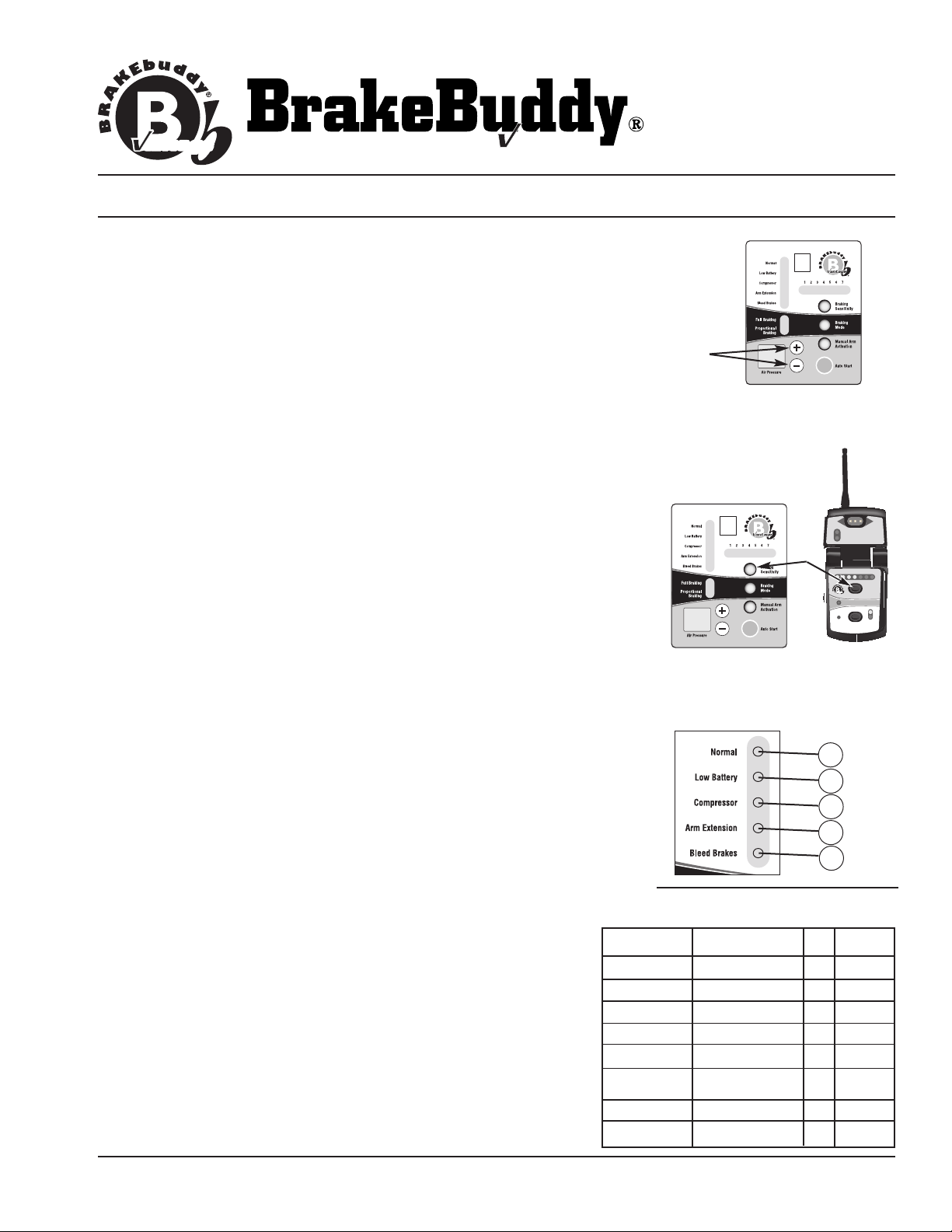
DIAGNOSTIC FEATURES:
The BrakeBuddy®Main Unit provides visual indication on problems
that are occurring (Fig. 12).
A - System Normal (present on main unit)
B - Battery Low (battery voltage has dropped below 10 volts)
Recharge towed vehicle battery before traveling.
C - Compressor Error (system is not pressurizing correctly) Call
technical service immediately 1-800-470-2287.
Arm Extension Error (arm is not retracted) Call technical service
D -
immediately 1-800-470-2287.
E - Bleed Brakes (depress the Auto Start button)
1-0288-053 Rev
31
. E 9/07
© 2004 Hopkins Manufacturing Corporation Printed in U.S.A
VEHICLE WEIGHT FORMULA
50
65
With Tow
Doll
60
75
Pounds
Kilograms Psi.
1,500 – 2,000 700 – 900 25 35
2,000 – 2,500 900 – 1,150 35 45
2,500 – 3,000 1,150 – 1,400 40 50
3,000 – 3,500 1,400 – 1,600 45 55
3,500 – 4,000 1,600 – 1,800
4,000 – 4,500 1,800 – 2,050 55 65
1999+ Jeep Gr. Cherokee
4,500 – 5,000 2,050 – 2,300
5,000 + 2,300 + 75 85
y
Pg. 3
 Loading...