

Page 1
Phone (800) 470-2287
Brakebuddy.com
Dedicated to towing safety
TM
TABLE OF CONTENTS
Congratulations on the purchase of your new BrakeBuddy®! The BrakeBuddy®was designed and built as an
auxiliary braking system to operate in conjunction with the existing braking system in your towed vehicle.
Use of the BrakeBuddy®in a manner inconsistent with these instructions may result in damage to your
vehicle, serious injury or death. You must read and understand these instructions prior to the use of this
product.
If you have any questions after reading these instructions, please call BrakeBuddy®customer service at 1 800-470-2287.
CONTENTS
Break Away Initial Installation . . . . . . . . . . . . . . . . . . . . . . . . . . . . . . . . . . . . . . . . .Page 2
Setup . . . . . . . . . . . . . . . . . . . . . . . . . . . . . . . . . . . . . . . . . . . . . . . . . . . . . . . . . . . .Page 4
Alert System . . . . . . . . . . . . . . . . . . . . . . . . . . . . . . . . . . . . . . . . . . . . . . . . . . . . . .Page 6
Operation Instructions . . . . . . . . . . . . . . . . . . . . . . . . . . . . . . . . . . . . . . . . . . . . . . .Page 7
Removal Instructions . . . . . . . . . . . . . . . . . . . . . . . . . . . . . . . . . . . . . . . . . . . . . . . .Page 8
Troubleshooting . . . . . . . . . . . . . . . . . . . . . . . . . . . . . . . . . . . . . . . . . . . . . . . . . . . .Page 9
Warranty . . . . . . . . . . . . . . . . . . . . . . . . . . . . . . . . . . . . . . . . . . . . . . . . . . . . . . . . .Page 10
Remove the BrakeBuddy®and components from the shipping carton. The complete system consists of:
Main BrakeBuddy®Unit
Clevis Assembly
Handle and Knob
Remote Alert System
Break-Away System
olt DC Cord
Alert
ransmitter
12 V
Control Panel
Handle
Break-A
(A) 1, 1/16” coiled break-
(B) 1 junction box with wiring
(C) 1 strap clamp
(D) 2 hex socket head
(E) 2 flat washers
(F) 2 lock washers
(G) 2 sheet metal screws
(H) 2 grommets
(I) 5 nylon ties
(J) 1 loose velcro patch
way Contents
away cable with one large
and one small clip on the
ends
harness
capscrews
H
I
E
F
J
A
D
G
Air Cylinder Arm
Clevis
Remote
T
B
C
E
F
D
Main Unit Components
311-0288-062 Rev. C 12/08
© 2008 Hopkins Manufacturing Corporation
Breakaway System Components
Pg. 1
Page 2
Dedicated to towing safety
BREAK-AWAY INSTALLATION
The Break-Away is an important part of the
BrakeBuddy system and is required by
law in most states. Do not operate
your BrakeBuddy without a properly
functioning Break-Away.
Phone (800) 470-2287
Brakebuddy.com
TM
J
FIG. 2
Installing Junction Box
Find a convenient, sturdy place on the
1.
front of your towed vehicle to mount
the junction box
installed on the driver’s side of the
vehicle if possible.
2. Clean the mounting surface and
attach the velcro patch (J) (Fig. 2).
3. Attach the junction box (B) to the
velcro patch (J) so the pin with the
ring faces forward and the wiring
harness feeds back into the engine
compartment.
4. Place the mounting bracket (C) over
the junction box (B) and mark the
hole locations to be drilled and
tapped.
5. Remove bracket (C) and junction box (B). Drill
marked holes with a1/8" metal drill bit.
NOTE: For thin sheet metal or plastic, it may be
necessary to reinforce the plastic or thin metal to
ensure the bracket will not separate from the
when the break-away pin is pulled. If you are going
to drill through thicker metal, use hex socket head
capscrews (D). You will need to drill a hole using a
#25 drill bit and tap the hole using a 10-24 tap.
(B). This should be
vehicle
B
C
D
G
FIG. 3
FIG. 4
K
6. Replace the junction box (B) and attach the
bracket (C) using hex socket head capscrews
(D) or sheet metal screws (G) provided (Fig. 3).
7. Locate a place in the firewall that will allow the
wiring harness to be fed through into the drivers’
side compartment of the towed vehicle. Use of
an existing hole would be most convenient.
8. If there is no existing hole, drill a 15/32"
diameter hole through the firewall (Fig. 4 /
Be careful not to drill into any functional
components of the vehicle.
9. Starting from the junction box (Fig. 4 / B), route
311-0288-062 Rev. C 12/08
© 2008 Hopkins Manufacturing Corporation
K).
B
M
H
Pg. 2
Page 3
Dedicated to towing safety
TM
BREAK-AWAY INSTALLATION
Phone (800) 470-2287
Brakebuddy.com
the black electrical wire up to the firewall
keeping it away from hot or moving engine
components. Secure using the nylon ties (I)
provided (Fig. 4 / M).
10. Feed the black wire through the hole in the
firewall and into the passenger compartment
(Fig. 5).
11. Place the split rubber grommet provided (H)
over the black electrical wire (Fig. 6) and
slide it into the 15/32" hole and fasten it into
place (Fig. 7).
NOTE: Failure to properly install the 15/32"
rubber grommet may result in harmful fumes
entering the vehicle, or damage to the wires.
Using the Break-Away System
After attaching your towed vehicle to your coach
and all hook-ups are complete, you will need to
attach the break-away cable (A) from the junction
box (B) to the motorhome. On the motorhome
end attach to a permanent location. The frame
of the vehicle is recommended. DO NOT
attach or wrap the cable around the tow bar,
hitch or bumper.
1. Attach the small clip on the cable (A) to the
loop on the pull pin of the junction box (Fig. 8 /
O), and then attach the large clip to the
motorhome (Fig. 8 / P). The coiled break-
away cable fits all applications and needs no
adjustment.
FIG. 8
FIG. 7
P
FIG. 5
Q
FIG. 6
O
2. Setup the BrakeBuddy in your towed vehicle
and plug the junction box wire harness into
the receptacles on top of the BrakeBuddy
(Fig.
9 / Q).
3. Before the start of every trip, pull the breakaway pin to test that the break-away system
activates the Brake Buddy.
4. When the use of the towed vehicle is needed,
simply unhook the small clip from the loop on
the pull pin of the junction box (B). Unplug the
junction box wire harness from the
BrakeBuddy and coil the wire under the
dashboard or under your floor mat (Fig. 10).
311-0288-062 Rev. C 12/08
© 2008 Hopkins Manufacturing Corporation
FIG. 9
FIG. 10
Pg. 3
Page 4
Dedicated to towing safety
Alert System
Test
Drain
Break-Away
TM
SETUP
Phone (800) 470-2287
Brakebuddy.com
1. Press the “Drain” button (A) to ensure there is no
FIG. 1
air pressure inside the unit (Figure 1).
2. Attach the lock nut and clevis assembly to the air
cylinder (Fig. 2).
3. Attach handle assembly to main unit (Fig. 3) with
adjustment knob.
4. Adjust the driver’s seat to the far back position
(Fig. 3). Place the BrakeBuddy®on the floorboard.
5. With the notched end of the clevis facing up,
attach the clevis to the top of the towed vehicle’s
brake pedal (Fig. 4). Angle the brake pedal clevis
so the upper portion of the clevis grabs the top of
the towed vehicle’s brake pedal. Pull down on the
lower portion of the clevis to extend the clevis under the bottom
of the towed vehicle’s brake pedal. Pull back very firmly on the
red tab (
B) until it locks into place securely. If attached correctly
the clevis should be locked securely around the vehicle’s brake
pedal.
6. Move the BrakeBuddy®forward until the Air Cylinder Arm is
fully retracted (Fig. 5). Make sure the vehicle’s brake pedal is
not being pressed.
A
FIG. 3
install handle
assembly
Move seat back.
FIG. 4
FIG. 2
B
7. Adjust the driver’s seat forward until it is less than a quarter
®
inch away from the BrakeBuddy’s
the handle (Fig. 6).
Again, make sure the vehicle’
handle or loosely touching
is not being pressed.
8. Power the BrakeBuddy
®
by plugging the unit into a 12-volt
receptacle in the towed vehicle (Fig. 8). When powered, the air
compressor will fill the air tank in under 1 minute. While the air
compressor is filling, the red sensitivity lights will descend from
7 to 1. If a 12-volt power supply is not available in the towed
position (or the 12-volt power remains off in the ignition off
position), a 12-volt Battery Direct Kit is available (part number
39305).
required to operate the BrakeBuddy
At a minimum, a 15-amp 12-volt power supply is
®
.
9. When the air compressor is completely filled, the red sensitivity
lights will display 1 through 5. This is signaling you to press the
Test button five times to (a) make sure the unit is performing
and adjusted properly; and (b) to remove the vacuum stored in
the towed vehicle’s brake vacuum reservoir, also known as
relieving vacuum.
311-0288-062 Rev. C 12/08
© 2008 Hopkins Manufacturing Corporation
s brake pedal
FIG. 5
Move BrakeBuddy®forward.
FIG. 6
Move seat forward.
Pg. 4
Page 5
Alert System
Tes t
Drain
Break-Away
Dedicated to towing safety
TM
SETUP
Phone (800) 470-2287
Brakebuddy.com
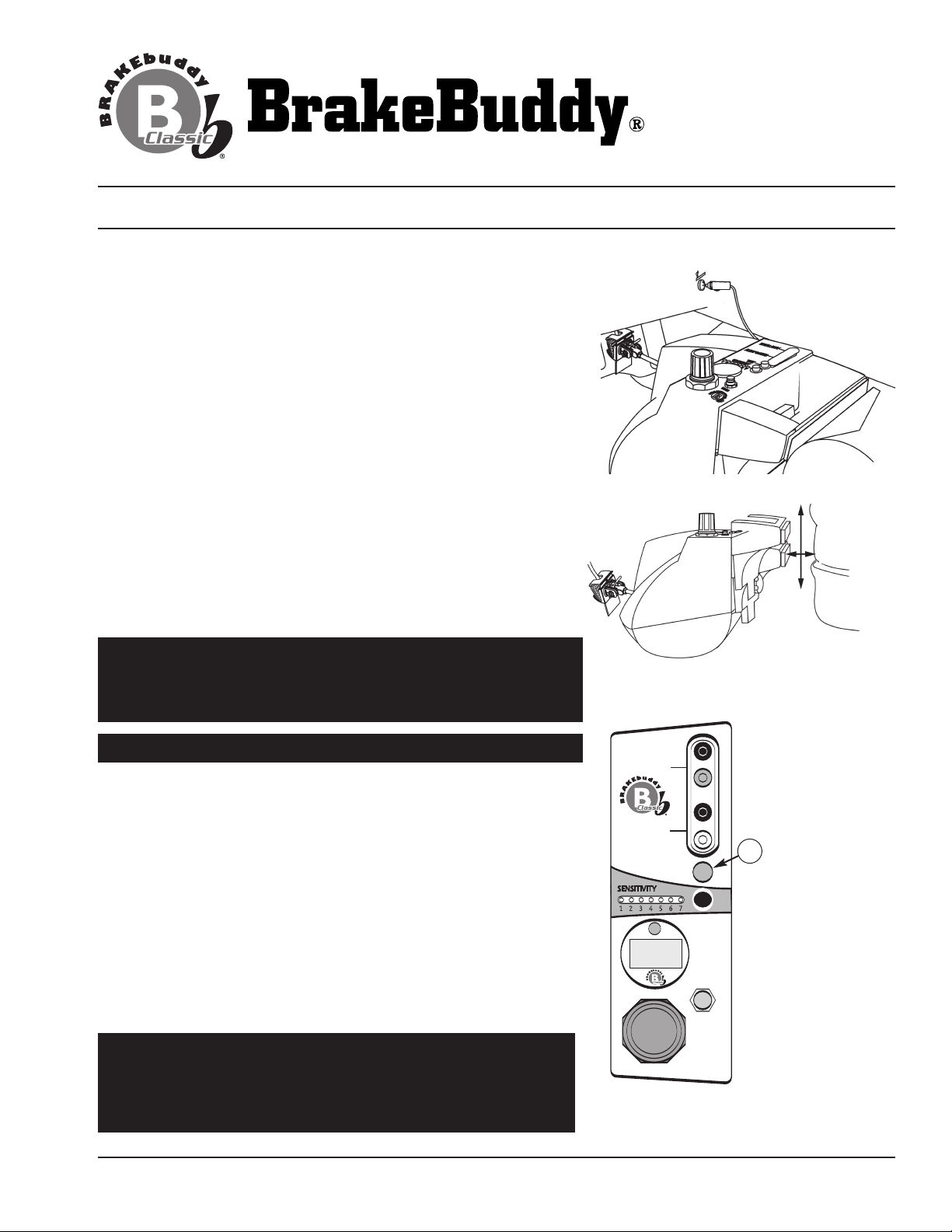
10.Press the Test button on the top BrakeBuddy®panel. The Test
button (Fig. 9 / C) will activate the arm one time. Use this time to
confirm that the unit is in the correct floor position.
®
11. If needed adjust the BrakeBuddy
adjustment knob on the back center portion of the BrakeBuddy
handle (Fig. 8). Loosen the
®
and adjust the height of the handle so it contacts the seat at the
lowest position possible without sliding under the seat. (NOTE: the
lower on the seat, the firmer the support). Tighten the adjustment
knob to secure handle. Repeat step 7 until the seat is in the
correct position.
12.After pressing the Test button the red sensitivity light will descend
from 5 to 4. When the seat is in the correct position press the Test
button four more times to completely relieve the brake vacuum.
®
(Make sure the BrakeBuddy
arm is pumping the brake when you
activate the Test button.) Each time the test button is pressed the
red sensitivity light will decrease by an increment of one.
After pressing the test button five times the sensitivity lights will
change to green indicating that the BrakeBuddy®has relieved the
vacuum of the towed vehicle’s brakes.
WARNING: For vehicles equipped with electric power assist
brakes, call BrakeBuddy®for further instructions 1-800-470-
2287. (Electric power assist brakes are common on hybrid
vehicles; please call BrakeBuddy®if you have questions).
FIG. 7
FIG. 8
Plug into 12v
accessory
receptacle.
Adjust handle
up or down to fit
seat at lowest
point.
FIG. 9
Do not tow your vehicle until the sensitivity lights are green.
ou may continue to press
If needed, make final seat adjustments.
13.
Y
the Test button as many times as needed to confirm that the
BrakeBuddy®unit is placed in the correct position.
IMPOR
T
Look at the brake lights at the rear of the to
:
ANT
vehicle to make sure they are not on. If the brake lights are
the BrakeBuddy
on,
®
is too c
lose to the brake pedal.
If for some reason the BrakeBuddy®does not fit your vehicle properly,
please call technical service at 1-800-470-2287.
NOTE:
A rubber floor mat under the BrakeBuddy
®
will not allow the
system to function properly and may result in damage. Please be
sure a carpet floor mat is being used.
ARNING:
W
Any time the towed vehicle’
s engine has been
started you must push the Test button 5 times after shutting
the towed vehicle’
the vehicle’
s brake system.
s engine off.
Failur
This removes the vacuum out of
e to drain the towed vehicle’
brake vacuum will result in excessive tire wear.
311-0288-062 Rev. C 12/08
© 2008 Hopkins Manufacturing Corporation
wed
C
s
Pg. 5
Page 6
Alert System
Tes t
Drain
Break-Away
Phone (800) 470-2287
Brakebuddy.com
Dedicated to towing safety
TM
ALERT SYSTEM INSTALLATION
The Alert System is a wireless monitor that illuminates on your motorhome’s dashboard when the BrakeBuddy is
activated telling you that the BrakeBuddy is working properly. This system consists of two parts, the Transmitter
and the Receiver.
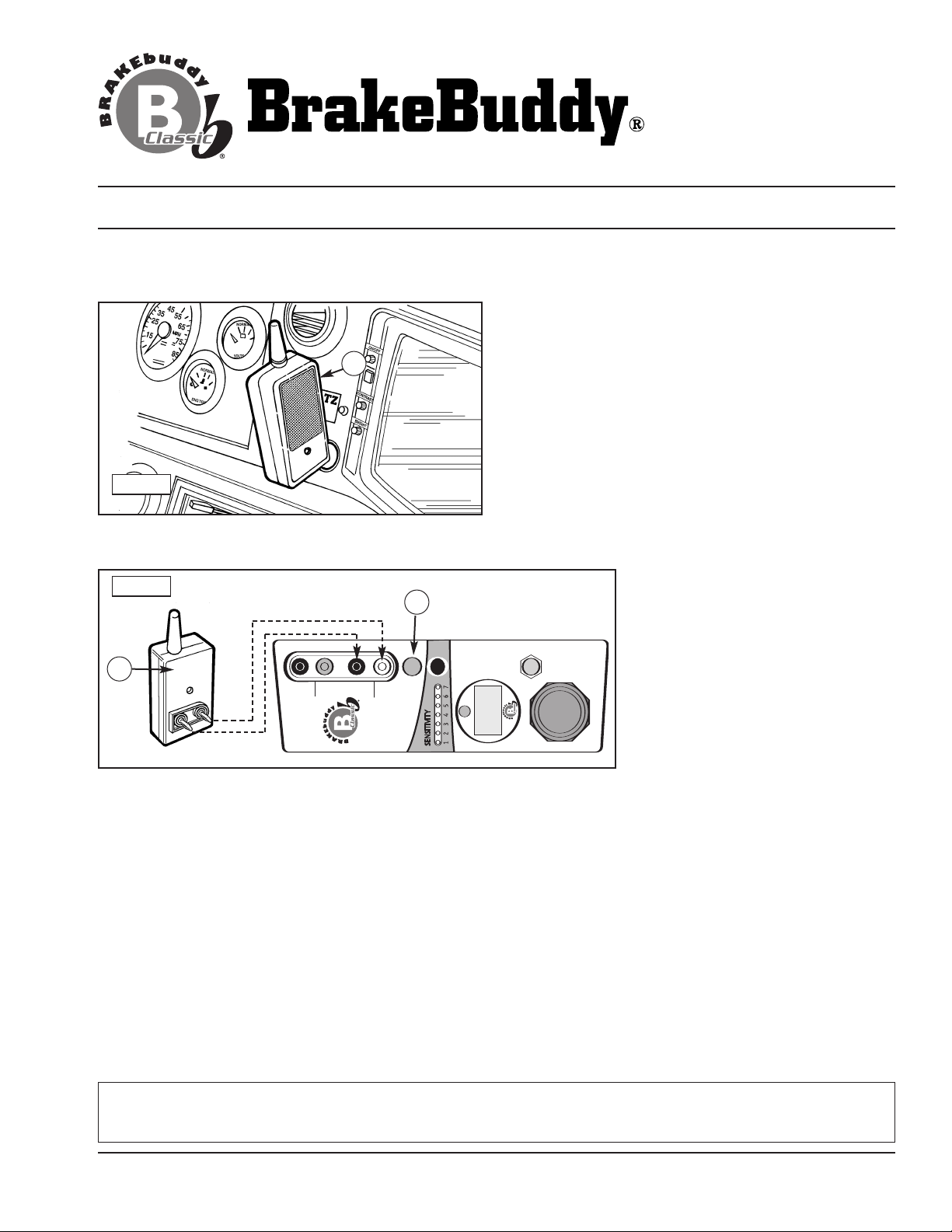
The Alert System Receiver (Fig. 10 / A) plugs into a
12-volt outlet on the dash of the motorhome. When the
BrakeBuddy®is activated in the towed vehicle, the
A
FIG. 10
Receiver will illuminate.
The receiver will continually flash red if the towed
vehicle’
s battery drops below 10 volts. Also, the
BrakeBuddy®main unit Sensitivity Settings #7, will flash
red in a low battery circumstance. At this time you need
to stop and restart your towed vehicle to recharge the
battery. Remember, always relieve the brake vacuum
after shutting the towed vehicle’s engine off.
If the towed vehicle breaks away from the motorhome
the receiver gives an audible signal and flashes red. The
audible will sound until the break-away pin is reinserted.
FIG. 11
Black
White
C
The Transmitter (Fig. 11 / B)
plugs into the top of the
BrakeBuddy®and sends a signal to
the Receiver when the
BrakeBuddy®is activated. Plug the
B
transmitter into the connections on
the BrakeBuddy®marked “Alert
System” (Fig. 2). The antenna
should point toward the
motorhome.
Test Procedure
Per
form each time before use.
Before you begin towing, a simple test should be performed to assure your Alert System is operating
properly. Have someone push the red test button on the BrakeBuddy®(Fig. 3 / C) and hold it for ten
seconds while you are in your parked motorhome looking at the Receiver. The Receiver should illuminate for
the full ten seconds without blinking. Do not do this while the motorhome is moving! The Alert Receiver will
illuminate: (1) when the test button is pressed; (2) when the BrakeBuddy activates as a result of forward
inertia (i.e., the braking of the motorhome) ; or (3) if the Break-Away pin is pulled.
NOTE:
In the unlikely circumstance that the receiver is plugged into a 12-volt outlet within 5 feet of the main unit, the
Receiver will not confirm braking activity. The BrakeBuddy®Classic will continue to operate the braking function,
but the receiver will not glow red to confirm braking.
NOTE: An optional transmitter extension cord is available if the signal is not reaching the receiver. Call
BrakeBuddy®customer service, 1-800-470-2287.
FCC/ID Notice: This device complies with Part 15 of FCC Rules. Operation is subject to the following two conditions: (1) This device
may not cause harmful interference, and (2) this device must accept any interference received, including interference that may cause
undesired operation.
311-0288-062 Rev. C 12/08
© 2008 Hopkins Manufacturing Corporation
Pg. 6
Page 7
Alert Syst
em
Tes t
Drain
Break-
Away
Dedicated to towing safety
TM
OPERATION INSTRUCTIONS
Phone (800) 470-2287
Brakebuddy.com
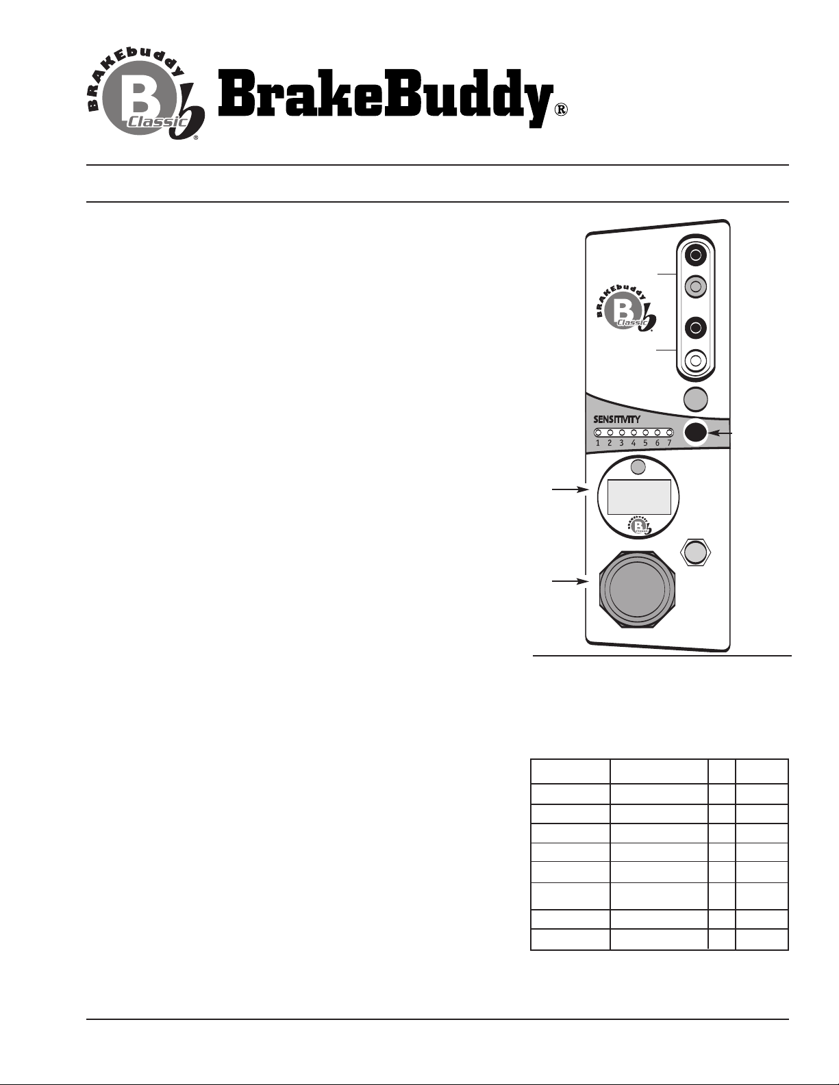
1. Adjust the air regulator knob to match the weight of your
towed vehicle (Figure 12). The braking pressure, or how hard
your towed vehicle will brake in tow, is adjusted by the air
®
regulator on top of the BrakeBuddy
. To find the correct
pressure setting for your vehicle, please refer to the Vehicle
Weight Formula Chart below. To adjust the setting, pull up on
the air regulator knob, turn knob until the pressure gauge reads
the correct setting specified by the Vehicle Weight Formula
Chart, and push the knob down to lock it in place. Press the red button
in the Digital Display to choose your preferred mode of weight
measurement of kilograms or Psi.
®
When the BrakeBuddy
engages, the towed vehicle should give
a slight and smooth tug on the motorhome. Note: Larger
motorhomes may not feel a tug when towing smaller vehicles.
As mentioned previously, the wireless Alert System also confirms
®
when and how long the BrakeBuddy
is activating.
2. Adjust the Sensitivity Button. The Sensitivity Button on the
top of the BrakeBuddy®determines how hard you must apply
the brakes in the motorhome before the BrakeBuddy will engage
the brakes in your towed vehicle. The sensitivity of the
BrakeBuddy®is adjusted by holding down the Sensitivity Button
(Figure 10). The more lights that are illuminated, the easier the
BrakeBuddy will activate. Each time the BrakeBuddy®is
installed, the sensitivity will return to the last setting used on
your previous trip.
NOTE: Your RV must be moving faster than 15 mph for the
BrakeBuddy to engage the brakes in the towed vehicle.
FIG. 12
Sensitivity
Button
Digital
Display
Air
Regulator
Knob
VEHICLE WEIGHT FORMULA
Settings are made by adjusting the air
regulator knob. Lift up and turn the knob
clockwise to increase pressure and
counter-clockwise to decrease pressure.
45
With
Dolly
Pounds
1,500 – 2,000 680
Kilograms Psi.
– 907 25 35
2,000 – 2,500 907 – 1,134 35 45
2,500 – 3,000 1,134 – 1,361 40 50
3,000 – 3,500 1,361 – 1,588
3,500 – 4,000 1,588 – 1,814 50 60
4,000 – 4,500 1,814 – 2,041 55 65
1999+ Jeep Gr
Cherok
.
ee
4,500 – 5,000 2,041 – 2,268 65 75
5,000 + 2,268 + 75 85
55
ow
T
311-0288-062 Rev. C 12/08
© 2008 Hopkins Manufacturing Corporation
NOTE: 1999 and newer Jeep Grand
Cherokees should be set at 55 psi.
Pg. 7
Page 8

Phone (800) 470-2287
Brakebuddy.com
Dedicated to towing safety
TM
REMOVAL INSTRUCTIONS
To remove the BrakeBuddy from your towed vehicle, unplug the unit, push the drain button to relieve the air
pressure in the system, adjust seat back and remove the BrakeBuddy.
CAUTION: Failure to drain your BrakeBuddy’s air system and unplug it from the car’s power source before
handling may cause damage to your vehicle, serious injury or death.
Information to User:
NOTE: This equipment has been tested and found to comply with the limits for a Class B digital device, pursuant
to part 15 of the FCC Rules. These limits are designed to provide reasonable protection against harmful
interference in a residential installation. FCC Radiation Exposure Statement to comply with FCC RF exposure
requirements in section 1.1307, a minimum separation distance of 1.40 cm (0.6 inches) is required between the
antenna and all persons. This equipment generates, uses and can radiate radio frequency energy and, if not
installed and used in accordance with the instructions, may cause harmful interference to radio communications.
However, there is no guarantee that interference will not occur in a particular installation. If this equipment does
cause harmful interference to radio or television reception, which can be determined by turning the equipment off
and on, the user is encouraged to try to correct the interference by one or more of the following measures:
- Reorient or relocate the receiving antenna.
- Increase the separation between the equipment and receiver.
- Connect the equipment into an outlet on a circuit different from that to which the receiver is
connected.
- Consult the dealer or an experienced radio / TV technician for help.
CAUTION: Changes or modifications not expressly approved by Hopkins Manufacturing Corporation could void
the user’s authority to operate the equipment.
311-0288-062 Rev. C 12/08 © 2008 Hopkins Manufacturing Corporation
Pg. 8
Page 9

Dedicated to towing safety
TM
TROUBLESHOOTING
TROUBLESHOOTING
Problem: The air compressor will not come on after I plug in the BrakeBuddy.
Solution: Check the air gauge for pressure in the tank. If the tank is already
Problem: The BrakeBuddy will not apply the brakes in the towed vehicle.
Solution: Make sure the air regulator is properly adjusted for the weight
Problem: The BrakeBuddy applies the brakes too hard in my towed vehicle.
Solution: Push the test button five times before towing to relieve the vacuum
pressurized, the compressor is designed to not come on until the
s pressure is reduced by BrakeBuddy activation. Make sure
tank’
there is power to the 12-volt receptacle and the fuse for the 12-volt
plug is functioning. If both are functioning, the green indicator light
on the 12-volt plug will be lit when it is plugged in. To remove the
fuse on the BrakeBuddy’s power cord, unscrew the finger nut on the
end of the plug. Replace fuse with a 15-amp fuse.
of the towed vehicle. Also check the sensitivity setting.
Remember, your RV must be moving at least 15 mph for the
BrakeBuddy to activate.
in the towed vehicle’s brake booster. Or adjust the air regulator knob
to reduce the air pressure.
Phone (800) 470-2287
Brakebuddy.com
Problem: The BrakeBuddy applies the brake as soon as I plug it in.
Solution: Check that the break-away system is properly connected and the
Problem: The compressor pumps up and then keeps on pumping slowly.
Solution: There may not be enough current to the BrakeBuddy. You may
Problem: I have to apply the brakes in my motorhome very hard for the Brake
Solution: Increase the sensitivity of the BrakeBuddy by pressing the
oblem:
Pr
Solution: The BrakeBuddy may be too close to the brake pedal thereby
Problem: The compressor will not start.
Solution: BrakeBuddy is designed with an automatic shut-off on the compressor
Problem: The seventh sensitivity light is flashing red.
Solution:
Problem: I’m experiencing frequent battery drain on my towed vehicle.
Solution: Battery drain can depend on your braking style and vehicle type. We recommend
pin is plugged into the junction box.
have a weak battery or you may need a “12-volt Battery Direct Kit”
(part number 39305). At a minimum, a 15-amp 12-volt cigarette lighter or
auxiliary power plug is required to operate the BrakeBuddy.
Buddy to come on.
sensitivity button.
The BrakeBuddy tur
applying the brakes in my motorhome.
activating the brake lights. See steps 6 - 12 of the setup
instructions.
when voltage drops to 9.5 volts.
If your towed vehicle’
sensitivity setting will warn you by flashing red.
will not operate if the towed vehicle’s battery in considerably low.
recharging the car battery once every three days to maintain optimum battery
condition.
(#39332). This accessory item continuously maintains the towed vehicle’s battery
charge. Contact your local dealer or BrakeBuddy to order
Another solution is to install the
ns my brake lights on even though I am not
s battery is significantly low the seventh light on the
The Brakebuddy System
owed V
T
ehicle Battery Maintainer
.
311-0288-062 Rev. C 12/08
© 2008 Hopkins Manufacturing Corporation
Pg. 9
Page 10

Dedicated to towing safety
TM
WARRANTY
Hopkins Manufacturing Corporation thanks you for purchasing BrakeBuddy.
A 3-year limited warranty and a 30-day money back guarantee apply to your
BrakeBuddy and BrakeBuddy accessories. An additional 2-year extended
warranty is also available (part number 39307). Call BrakeBuddy customer
service at 1-800-470-2287. We wish you safe and happy travels.
LIMITED THREE-YEAR WARRANTY
WHAT IS COVERED AND FOR HOW LONG?
We are confident our product will perform well and therefore warrant
to you, as the original retail purchaser, for a period of three years from
the date of original purchase, that your new product will be free of
mechanical and electrical defects in material and workmanship.
WHAT WILL BRAKEBUDDY DO? HOW DO I GET SERVICE?
During the warranty period, we will repair or replace your new
product (at our option) without cost to you, which will be your
exclusive remedy under this warranty. Please do not return this
product to the place of purchase. Doing so may delay the
processing of your claim and our repair of your product. Return your
product postage prepaid, with proof of purchase. Please call BrakeBuddy
customer service for shipping instructions.
Phone (800) 470-2287
Brakebuddy.com
WHAT IS NOT COVERED?
Our warranty for your product will not cover damage resulting
from neglect or misuse of the product, use of improper voltage
or current, use contrary to operating instructions, or disassembly,
repair, or alteration by any person other than an authorized
service station. Any implied warranty of merchantability or
fitness for a particular purpose of your product is limited to the
duration of this written warranty. We shall not be liable for any
incidental or consequential damages for breach of any expressed
or implied warranty on your product.
HOW YOUR STATE'S LAWS MAY APPLY:
Some states do not allow limitations on how long an implied
warranty lasts or the exclusion or limitation of incidental or
consequential damages, so the above limitation may not apply
to you.
This warranty gives you specific legal rights, and you
may also have other rights, which vary from state to state.
311-0288-062 Rev. C 12/08 © 2008 Hopkins Manufacturing Corporation
Pg. 10
 Loading...