

Hopkins BB002 Users Manual
INSTALLATION MANUAL
antage
antage
antage
Phone (800) 470-2287
ww.brakebuddy.com
w
Congratulations on the purchase of your new BrakeBuddy! The
BrakeBuddy was designed and built as an auxiliary braking
system to operate in conjunction with the existing braking
system in your towed vehicle.
Use of the BrakeBuddy in a manner inconsistent with these
instructions may result in damage to your vehicle, serious injury
or death. You must read and understand these instructions
prior to the use of this product.
If you have any questions after reading these instructions, please
call BrakeBuddy customer service at 1-800-470-2287.
1. Remove the BrakeBuddy and components from the shipping
carton. The complete system consists of:
Main BrakeBuddy Unit
Breakaway System
Clevis Assembly
Remote Alert System
2. Install the breakaway system by following the step-by-step
instructions included with the breakaway kit.
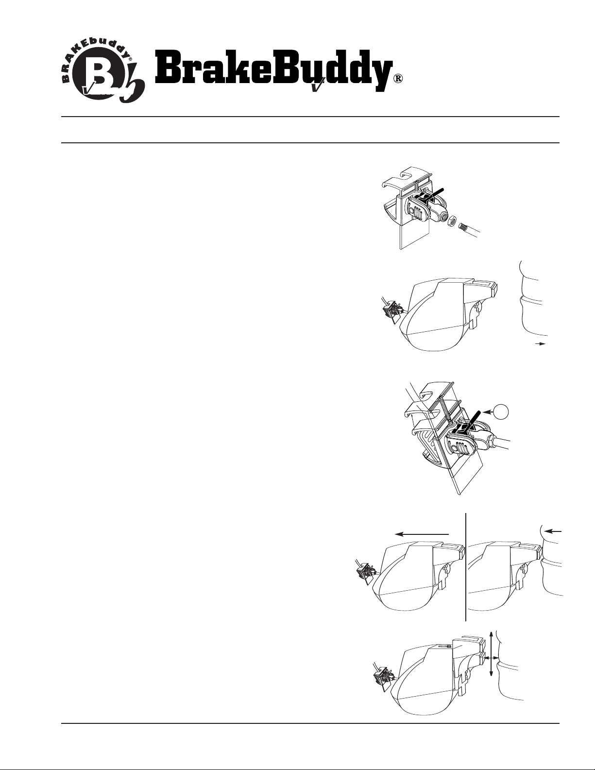
3. Attach the lock nut and clevis assembly to the air cylinder (Fig.1).
4. Adjust the driver’s seat to the far back position (Fig. 2). Place the
BrakeBuddy on the floorboard between the seat and the brake
pedal. Slide the BrakeBuddy back against the seat for maximum
working room.
FIG. 1
FIG. 2
Move seat back.
FIG. 3
A
5. With the notched end of the clevis facing up, attach the clevis to
6. Move the BrakeBuddy forward until the air cylinder rod is fully
7. Adjust the driver’s seat forward until it touches the handle on the
8. Adjust the BrakeBuddy handle (Fig. 6). Loosen the adjustment
the top of the towed vehicle’s brake pedal (Fig. 3). Angle the
brake pedal clevis so the upper portion of the clevis grabs the top
of the towed vehicle’s brake pedal. Pull down on the air cylinder
rod (or lower portion of the clevis) to extend the clevis under the
bottom of the towed vehicle’s brake pedal. Pull back on the red
locking tab (A) until secure (tab should not go all the way down).
retracted (Fig. 4). Make sure the brake pedal is not being
pressed.
back on the BrakeBuddy (Fig. 5).
knob on the back center portion of the BrakeBuddy and adjust the
height of the handle so it contacts the seat at the lowest position
possible without sliding under the seat. (NOTE: the lower on the
ighten the adjustment knob to
seat, the firmer the support).
T
secure handle.
311-0288-053 Rev. A 11/05
© 2004 Hopkins Manufacturing Corporation Printed in U.S.A
FIG. 4 FIG. 5
Move BrakeBuddy forward.
FIG. 6
Move seat forward.
Adjust handle
up or down to fit
seat at lowest
point.
Lighter
INSTALLATION MANUAL
antage
antage
antage
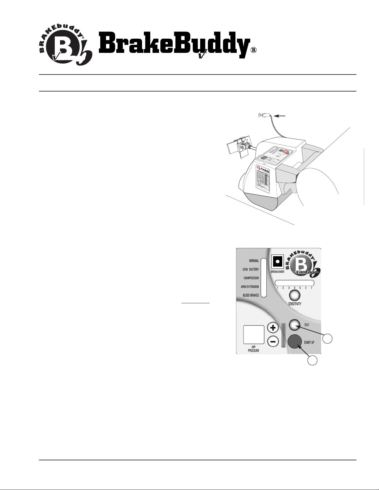
9. Power the BrakeBuddy (Fig. 7). To power the BrakeBuddy,
plug the unit into a 12-volt receptacle in the towed vehicle.
When powered, the air compressor will fill the air tank in 30-40
seconds. If a 12-volt power supply is not available in the
towed position (or the 12-volt power remains off in the ignition
off position), a 12-volt Battery Direct Kit is available (part
number 39305). At a minimum, a 15-amp 12-volt power supply
is required to operate the BrakeBuddy.
“bleed brakes” light will be lit until completion of step 10.
10. Push the red AUTO START button located on top of the
BrakeBuddy (Fig. 8).
The arm will automatically extend / cycle
5 times. This will remove any vacuum stored in the brake
vacuum reservoir of the towed vehicle as well as diagnose
any errors in the system startup (B).
NOTE: While the arm is activating, look at the brake lights
on the rear of the towed vehicle. The brake lights will
fluctuate on and off as the BrakeBuddy is pressing on
and off the brake pedal. If the brake lights remain on, the
BrakeBuddy unit is too close to the brake pedal.
NOTE: After Auto Start cycle is complete, the red “bleed
brakes” light will go out and the green “normal” light will
be on.
NOTE: The test button (Fig. 8 /
arm activation test. The test button can be used to
confirm the unit is in the correct floor position.
NOTE: The red
C) is a manual (one time)
FIG. 7
FIG. 8
Phone (800) 470-2287
ww.brakebuddy.com
w
lug into 12-volt
P
ccessory
a
receptacle.
WARNING:
Any time the towed vehicle’s engine has been started
(e.g., running through gears, charging battery, etc.)
push the Auto Start after shutting the towed vehicle’s engine
off. This removes the vacuum out of the vehicle’s brake system.
Failure to drain the towed vehicle’s brake vacuum will result in
excessive tire wear
.
11. Make final seat adjustments. If there is a gap between the
seat and handle, adjust the seat forward to close the gap.
311-0288-053 Rev. A 11/05 © 2004 Hopkins Manufacturing Corporation Printed in U.S.A
You Must
C
B
 Loading...