

Hoover GUV L2310, GUV L2315 Owner's Manual

HOOVER
GUV TM Garage
Owner's Manual
English -) pp. 1-7
Espa_ol-), p. 8-12
Frangais -.), p.14-18
Utility Vac
®
This cleaner was inspected and packaged
carefully before being shipped from the
factory. If you should happen to need
assistance during assembly or operation,
Visit us on-line at www.hoover.eom to find
the service outlet nearest you (click on the
"Service" button)
OR
Call 1-800-944-9200 for automated referral of
authorized service outlet locations (U.S. only)
OR
Call 1-800-263-6376 to speak with a
representative in our Consumer Response
Center. Men-Fri 8AM-7PM EST.
I
J
J
PLEASE DO NOT RETURN THIS
PRODUCT TO THE STORE.
Review this manual before operating cleaner.
Fill in and retain
For your records, please enter model and serial numbers in the spaces provided
below and retain in a safe place.
Model No. Serial No.
(See side of power unit)
Attach your sales receipt to this owner's manual. Verification of purchase date
may be required for warranty service.
Important Safeoguaards!
When using an electrical appliance, always follow including
the following:
READ ALL INSTRUCTIONS BEFORE USING THIS APPLIANCE
Index
GUV TM vac description ................ 3
Grounding instructions .............. 3
Installation .................................... 4
How to use ................................... 4
Important safeguards .................. 2
Maintenance ................................. 5
If you have a problem ............. 5
Thermal protector ................... 6
Lubrication ............................... 6
Service ..................................... 6
Warranty ....................................... 7
W; ing:arn _o reduce the risk of fire, electric shock, or injury:
• Do not use on wet surfaces.
• Connect to a properly grounded outlet only. See "Grounding Instructions."
• Close supervision is necessary when any appliance is used by or near children.
Do not allow cleaning system to be used as a toy or to run unattended at any time.
• Do not allow any objects to be put into hose inlet.
• Do not pick up anything that is burning or smoking, such as cigarettes,
matches, or hot ashes.
• Do not use to pick up flammable or combustible liquids such as gasoline or fine
wood sandings or use in areas where they may be present.
• Avoid picking up sharp objects.
• Do not use without filter in place. Empty dirt container and clean filter
frequently when picking up very fine materials such as powder.
• Use extra care when cleaning stairs.
• Do not put any objects into openings. Do not use with any openings blocked:
keep free of dust, lint, hair, and anything that may reduce air flow.
• Do not pull or carry by cord, use cord as a handle, close a door on cord or pull
cord around sharp edges or corners. Do not run appliance over cord. Keep
cord away from heated surfaces.
• Always disconnect cord from electrical outlet before servicing the power unit.
• Do not unplug by pulling on cord. To unplug, grasp the plug, not the cord.
Never handle plug or appliance with wet hands.
• Unplug cleaner when not in use. Turn off all controls before unplugging.
• Do not use with damaged cord or plug. If appliance is not working as it should,
has been dropped, damaged, left outdoors, or dropped into water, take it to a
Hoover Factory Service Center or Authorized Hoover Warranty Service Dealer
(Depot).
• Use vacuum cleaner only for its intended use as described in this owner's
manual. Use only attachments recommended by The Hoover Company; others
may cause hazards.
c us Save these instructions!
©2007 Hoover, Inc.
www.hoover.com
2

Operatecleaningsystemonlyat
voltagespecifiedon powerunit.
Thissystemis intendedfor resi-
dentialuse.
Thissystemis designedfor dry
pick-uponly.
Grounding
Instructions
This appliance must be grounded. If
it should malfunction or breakdown,
grounding provides a path of least
resistance for electrical current to
reduce the risk of electric shock. This
appliance is equipped with a cord hav-
ing an equipment-grounding conductor
(A) and grounding plug (B). The plug
must be plugged into an appropriate
outlet (C) that is properly installed and
grounded in accordance with all local
codes and ordinances.
DANGER-
Improper connection of the equipment-
grounding conductor can result in the
risk of electric shock. Check with a
qualified electrician or service person if
you are in doubt as to whether the outlet
is properly grounded. Do not modify
the plug provided with the appliance
- if it will not fit the outlet, have a proper
outlet installed by a qualified electrician.
This appliance is for use on a nominal
120 volt circuit and has a grounding
plug that looks like the plug illustrated in
Fig. 1-1.
A Temporary adapter (D) may be used
to connect this plug to a 2-pole recep-
tacle (E) if a properly grounded outlet is
not available. The Temporary adapter
should be used only until a properly
grounded outlet (C) can be installed by
a qualified electrician. The green col-
ored rigid ear (F), lug, or the like extend-
ing from the adapter must be connected
to a permanent ground such as a
properly grounded outlet box cover.
Whenever the adapter is used, it must
be held in place by a metal screw (G).
MM
III l_i
In l\
I i I
G-
F
E
NOTE: In Canada, the use of a tem-
porary adapter is Not Permitted by the
Canadian Electrical Code.
Description
10
11
)
)
8
-
t
1. Motor module
2. Motor exhaust (back of unit)
3. Hose inlet
4. Dirt container (contains
Mounting bracket - Fig. 2-1
and tools - Fig. 3-2)
5. ON-OFF switch
6. Power cord (back of unit)
7. Data label
8. Mounting bracket
9. Hose rack
10. Tools
11. Tool caddy
12. Hose (L2310 - 30ft.; L2315 - 35ft.)
(packed inside dirt container)
12
Mounting location
The GUVTM power unit can be mounted
in the garage, basement, utility room,
or any other remote area, except where
ex-posed to weather, and no more than
5 feet from an electrical outlet. Because
this unit requires ventilation, DO NOT
install in a heat producing or confined
area such as the attic, furnace room, etc.
The top of the GUVTM power unit should
be no less than 12" (30.5 cm) from the
ceiling, and any corner wall to allow
proper cooling of the motor. For ease of
removing the dirt container, the bottom
of the unit should be at least 18" (46 cm)
above the floor.
DO NOT block the two small inlet holes
located above each latch holder.
Because the top surface of the GUVTM
power unit gets hot during operation,
DO NOT place or store any objects on
top of the unit.
UNDER NO CIRCUMSTANCES
SHOULD AN EXTENSION CORD BE
USED WITH THIS APPLIANCE.
Mounting the GUV TM
power unit and hose
rack
1) Determine if the wall you will be
mounting the GUVTM power unit to is
block, concrete, or plaster/drywall.
2) Drywall or Plaster Wall (fasteners
included)
GUVTM power unit: Locate a stud
and drill a 9/64" (.36 cm) dia. x 1-1/4"
(3.18 cm) pilot hole. Mount the brack-
et from the top center hole with a
screw. Making sure that the bracket
is straight, drill a second pilot hole
using the lower hole on the bracket
as a guide and fasten tightly with the
other screw. If no stud isavailable,
drill a 1/4" (.64 cm) dia. x 1-1/4" (3.18
cm) pilot hole and use anchor drywall
mounts.
3) Block or Concrete Wall (fasteners
are not included)
GUVTM power unit: You will need (2)
1-1/2" (3.8 cm) x 1/4" (.64 cm) lead
plugs and (2) 1-1/2" (3.8 cm) x 1/4"
(.64 cm) lag bolts. Drill a 1/2" (1.3
cm) dia. x 1-3/4" (4.4 cm) deep hole
with a masonry drill bit. Insert a lead
plug into the hole.
W
MOUNTING
BRACKET
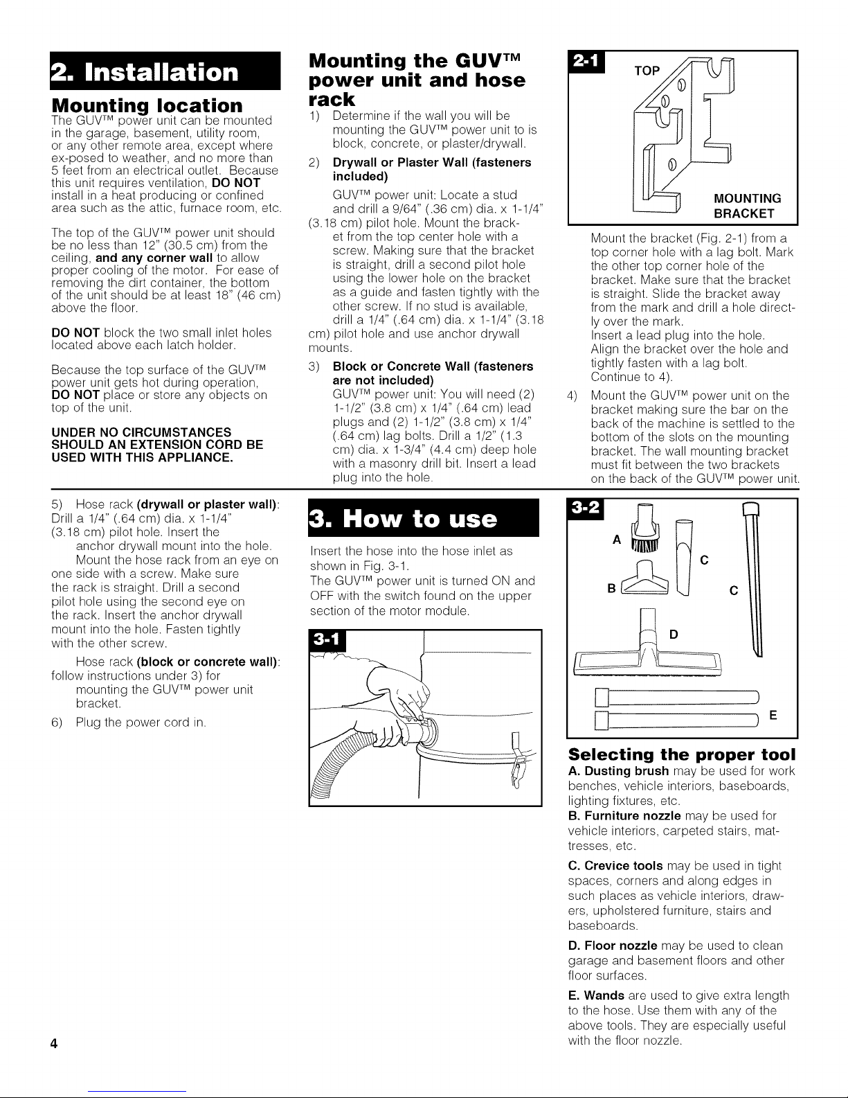
Mount the bracket (Fig. 2-1) from a
top corner hole with a lag bolt. Mark
the other top corner hole of the
bracket. Make sure that the bracket
is straight. Slide the bracket away
from the mark and drill a hole direct-
ly over the mark.
Insert a lead plug into the hole.
Align the bracket over the hole and
tightly fasten with a lag bolt.
Continue to 4).
4)
Mount the GUV TM power unit on the
bracket making sure the bar on the
back of the machine is settled to the
bottom of the slots on the mounting
bracket. The wall mounting bracket
must fit between the two brackets
on the back of the GUVTM power unit.
5) Hose rack (drywall or plaster wall):
Drill a 1/4" (.64 cm) dia. x 1-1/4"
(3.18 cm) pilot hole. Insert the
anchor drywall mount into the hole.
Mount the hose rack from an eye on
one side with a screw. Make sure
the rack is straight. Drill a second
pilot hole using the second eye on
the rack. Insert the anchor drywall
mount into the hole. Fasten tightly
with the other screw.
Hose rack (block or concrete wall):
follow instructions under 3) for
mounting the GUVTM power unit
bracket.
6) Plug the power cord in.
4
Insert the hose into the hose inlet as
shown in Fig. 3-1.
The GUV TM power unit is turned ON and
OFF with the switch found on the upper
section of the motor module.
A
B
C
[] )
) E
Selecting the proper tool
A. Dusting brush may be used for work
benches, vehicle interiors, baseboards,
lighting fixtures, etc.
B. Furniture nozzle may be used for
vehicle interiors, carpeted stairs, mat-
tresses, etc.
C. Crevice tools may be used in tight
spaces, corners and along edges in
such places as vehicle interiors, draw-
ers, upholstered furniture, stairs and
baseboards.
D. Floor nozzle may be used to clean
garage and basement floors and other
floor surfaces.
E. Wands are used to give extra length
to the hose. Use them with any of the
above tools. They are especially useful
with the floor nozzle.
Disconnect cord from electrical outlet
before removing dirt container.
Under normal circumstances, the only
maintenance your GUVTM vac requires is
emptying the dirt container as required,
and periodically cleaning the filter.
Attaching wand and
tools
Attach any tool or wand to the hose by
pushing it firmly into hose.
Attach second wand or tool to wand by
pushing it firmly onto the wand.
Twist wand or tool slightly to tighten or
loosen the connection.
How to clean tools
To clean the hose, wipe off dirt with a
cloth dampened in a mild detergent.
Rinse with a damp cloth.
Cleaning tools may be washed in warm
water with a detergent. Rinse and air dry
before using.
To clean the dirt container:
1) Remove the dirt container by
unlatching the latches located on each
side of the container.
2) Empty the dirt container into a trash
receptacle.
3) Replace dirt container, aligning
latches and latch holders, and secure
latches.
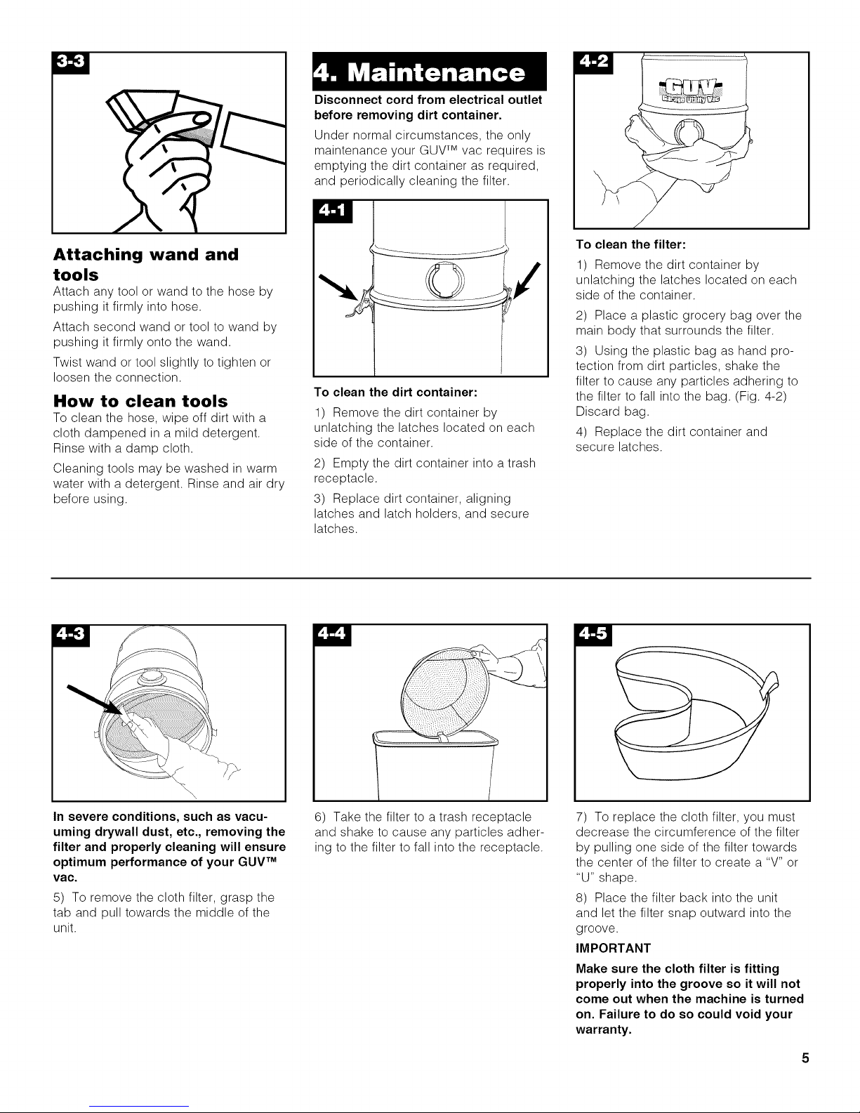
To clean the filter:
1) Remove the dirt container by
unlatching the latches located on each
side of the container.
2) Place a plastic grocery bag over the
main body that surrounds the filter.
3) Using the plastic bag as hand pro-
tection from dirt particles, shake the
filter to cause any particles adhering to
the filter to fall into the bag. (Fig. 4-2)
Discard bag.
4) Replace the dirt container and
secure latches.
In severe conditions, such as vacu-
uming drywall dust, etc., removing the
filter and properly cleaning will ensure
optimum performance of your GUV TM
vac.
5) To remove the cloth filter, grasp the
tab and pull towards the middle of the
unit.
6) Take the filter to a trash receptacle
and shake to cause any particles adher-
ing to the filter to fall into the receptacle.
7) To replace the cloth filter, you must
decrease the circumference of the filter
by pulling one side of the filter towards
the center of the filter to create a "V" or
"U" shape.
8) Place the filter back into the unit
and let the filter snap outward into the
groove.
IMPORTANT
Make sure the cloth filter is fitting
properly into the groove so it will not
come out when the machine is turned
on. Failure to do so could void your
warranty.

If a minor problem develops, it usually
can be remedied quite easily when the
cause is found by using the check list
below.
Possible cause
Possible solution
• Not firmly plugged in
• Plug in firmly
• No voltage in wall receptacle
• Check fuse or breaker
• Blown fuse/tripped breaker
• Replace fuse/reset breaker
• Thermal protector activated
• Allow thermal protector to cool for
30 minutes (this will allow the ther-
mal protector to reset).
Possible cause
Possible solution
• Filter dirty
• Clean filter
• Obstruction in hose or cleaning
tools
• If the blockage is in the hose, dis-
connect hose from power unit.
Insert a long blunt item, such as a
broom handle, to clear the block-
age.
• Check tools, wands, etc. for
blockages.
• Dirt container full or misposi-
tioned
• Check to see if the dirt container
needs to be emptied.
• Check to see if the dirt container
is properly positioned and secure-
ly attached.
Thermal protector
An internal thermal protector has been
designed into your cleaner to protect it
from overheating.
When the thermal protector activates,
the cleaner will stop running. If this
happens, proceed as follows:
1. Turn the cleaner OFF and discon-
nect it from the electrical outlet.
2. Check filter for dirt accumulation.
3. Refer to "Suction low" section under
"If you have a problem".
4. When cleaner is unplugged and the
motor cools for 30 minutes, the thermal
protector automatically resets and clean-
ing may continue.
If the thermal protector continues to
activate after following the above steps,
your cleaner may need servicing (see
"Service" section).
Lubrication
The motor is equipped with bearings
that contain sufficient lubrication for the
life of the motor. The addition of lubricant
could cause damage. Therefore, do not
add lubricant to motor bearings.
Service
To obtain approved HOOVER service
and genuine HOOVER parts, locate the
nearest Hoover Factory Service Center
or Authorized Hoover Warranty
Service Dealer (Depot) by:
• checking the Yellow Pages under
"Vacuum Cleaners - Household"
OR-
• checking the Service section of
The Hoover Company on-line at
www.hoover.com
OR-
• calling 1-800-944-9200 for an auto-
mated referral of authorized ser-
vice outlet locations (U.S. only).
Do not send your cleaner to Hoover,
Inc. in Glenwillow for service, as this will
only result in delay.
Call 1-800-263-6376 to speak with a rep-
resentative in our Consumer Response
Center. Mon-Fri 8am-7pm EST.
In Canada, contact Hoover Canada,
Carson Building, 100 Carson Street,
Etobicoke, Ontario, M8W 3R9.
Phone: 1-800-263-6376, Mon-Fri 8am-
7pm EST.
Always identify your cleaner by the
complete model number when request-
ing information or ordering parts. (The
model number appears on the side of
the unit.)
6
 Loading...