


Vertex Continuous Gas Monitor
Operating Manual
• Table of Contents
• Introduction
• Installation
• Startup
• Operation
• Maintenance
• Troubleshooting
• Installation Drawings
• Specications
• Detectable Gases
• Replacement/Consumable
• Optional Relay Specs
• Network Interfaces
• LIT Option
• Warranty Statement
Vertex
N OT I C E
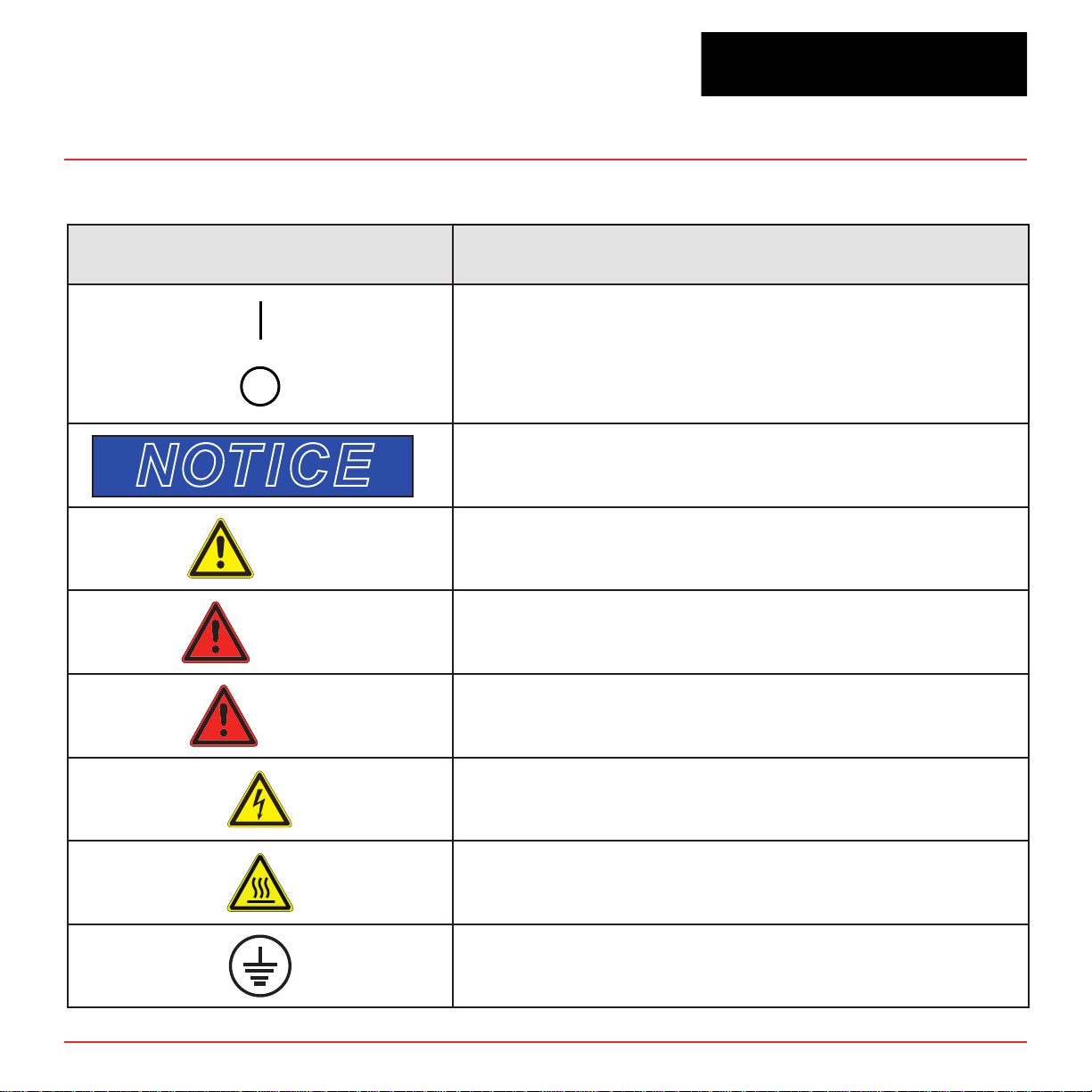
Vertex Continuous Monitor Symbols
Symbol Description
Power on
Power off
Potential damage to the device or other property, maintenance
procedures, and “refer to manual” instructions.
Lifting instructions, low clearances, slipping/tripping hazards,
minor corrosive dangers. Also used when defining personal
CAUTION
WARNING
protective equipment (gloves, dust masks, etc.)
Personal injury risk: machinery hazards around guarded
equipment, moving parts, crush/pinch hazards, flying debris, and
arc flash hazards.
TM
72-Point Continuous Monitor
DANGER
V ertex Technical Handbook
The most dangerous or potentially lethal hazards: unguarded
equipment, confined space entrances, and lockout labels.
Caution: possibility of electric shock
Caution: hot surface
Protective conductor terminal (ground terminal)
i
Vertex
TM
72-Point Continuous Monitor
EMC Considerations
Your Honeywell Analytics continuous gas monitor
has been designed to comply with applicable
Electromagnetic Compatibility (EMC) standards
at the time of manufacture. The design includes
filtering, shielding and bypassing techniques. At
the time of certification, simulated customer Input/
Output (I/O) schemes were tested.
All methods used in your equipment for emission
suppression and reduction of susceptibility are
interactive. Modifications to the monitor could result
in increased emissions and higher vulnerability to
other radiated fields.
Following the guidelines in this EMC Considerations
section will ensure your monitor maintains the
highest degree of EMC integrity. The guidelines
listed apply only to I/O emissions and do not apply
to A.C. and D.C. monitor power connections.
Industry Canada Statement
This device complies with Industry Canada licenceexempt RSS standard(s). Operation is subject to
the following tw o conditions: (1) this de vice may not
cause interference, and (2) this de vice must accept
any interference, including interference that may
cause undesired operation of the device.
Le présent appareil est conforme aux CNR
d’Industrie Canada applicables aux appareils radio
ex empts de licence. L’e xploitation est autorisée aux
deux conditions suivantes : (1) l’appareil ne doit pas
produire de brouillage, et (2) l’utilisateur de l’appareil
doit accepter tout brouillage radioélectrique
subi, même si le brouillage est susceptible d’en
compromettre le fonctionnement.
FCC Compliance Statement
CAUTION: Changes or modifications
not expressly approved could void
your authority to use this equipment.
Th
is device complies with Part 15 of the FCC Rules.
Operation to the following two conditions: (1) This
device ma y not cause harmful interference , and (2) this
device must accept any interference received,
including interference that may cause undesired
operation.
V ertex Technical Handbook
ii
Vertex
TM
72-Point Continuous Monitor
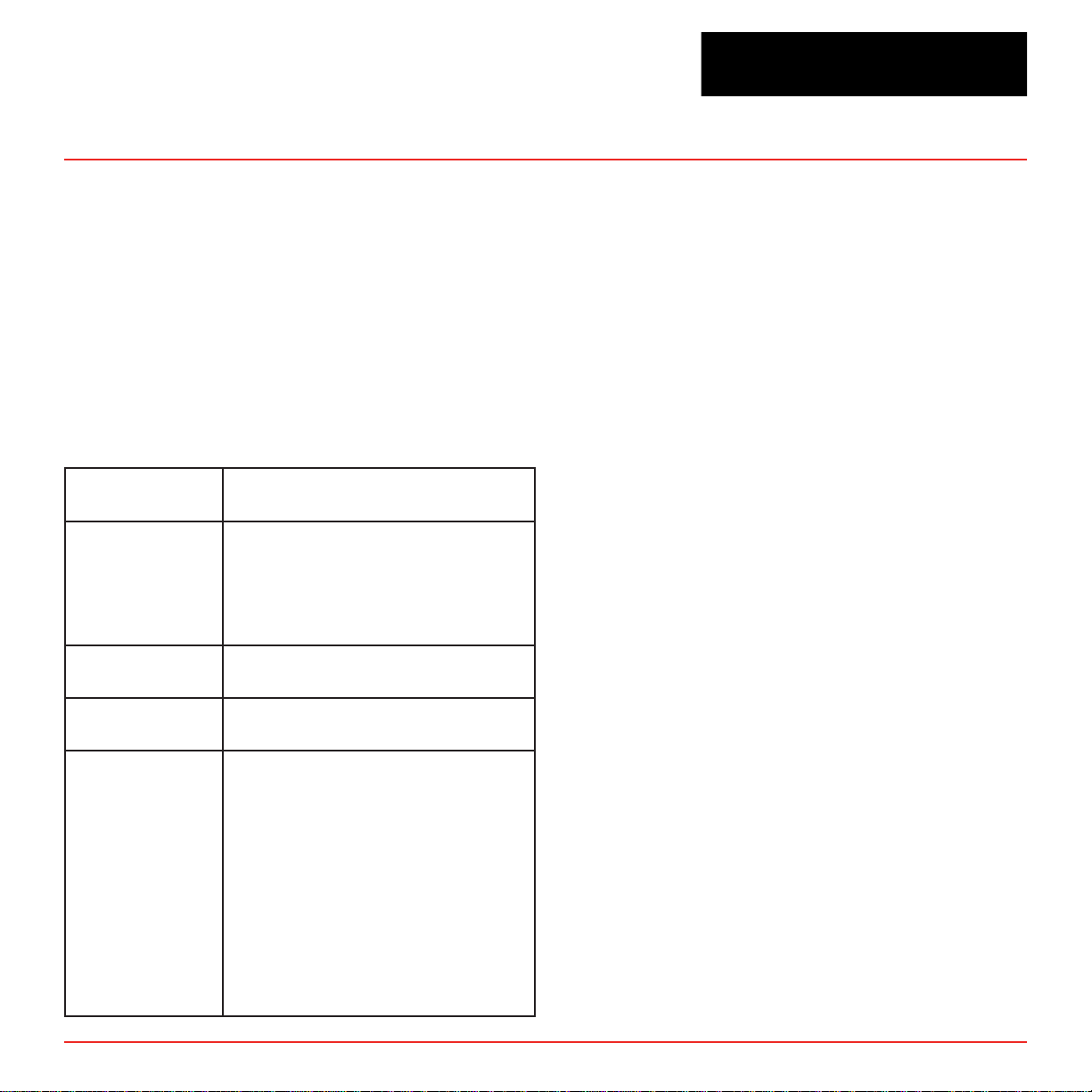
Cabling
At a very minimum, all cables should include a
braided shield. Ideal results have been obtained
with twisted pair cabling which has a foil shield
surrounding each pair plus foil and 90% braid
shielding around the bundle. In addition, ensure
local electrical code requirements are met.
The following cable parameters must be
considered:
Braid
Foil
Twisted Pair
Stranded Pair
Shield
Termination
Must have a minimum 90%
coverage
When used with braid, provides
100% coverage
Do not use foil alone. It has a
tendency to break.
Provides for cancelling of
magnetic fields
Provides the greatest surface
area
Continuation of the shield to the
cabinet earth ground is most
important.
For discrete wire terminations,
pigtails to the cabinet (connector)
ground should be extremely short
(absolutely no greater than three
inches).
For multiconductor connector
terminations, only 360° shielded
shells should be used.
Note:
Honeywell Analytics product testing uses >90%
braid with foil (around the bundle); twisted
pair; stranded 24 AWG (minimum wiring for all
qualication and certication testing.)
Connectors
All qualification and certification of Honeywell
Analytics products were achiev ed with high quality
connectors, providing 360° shield cov erage. These
connectors generally had metal shells.
Failure to properly secure the connector to the
equipment will result in high emission levels.
Also, poorly constructed or improperly assembled
connectors can be a high source of radiated noise
and provide a path for external signals into the
monitor.
V ertex Technical Handbook
iii
Vertex
TM
72-Point Continuous Monitor
Table of Contents
Vertex Continuous Monitor Symbols ����������������������������������������������������������������������������������� i
EMC Considerations
Cabling ������������������������������������������������������������������������������������������������������������������������������ ii
Connectors ����������������������������������������������������������������������������������������������������������������� iii
1 Introduction
1�1 System Overview ���������������������������������������������������������������������������������������������������������1-2
1�1�1 Manufacturer �������������������������������������������������������������������������������������������������������1-2
1�1�2 General Safety �����������������������������������������������������������������������������������������������������1-2
1�2 System Components ���������������������������������������������������������������������������������������������������1-2
1�2�1 Vertex Front ���������������������������������������������������������������������������������������������������������1-3
1�2�2 Vertex Back ���������������������������������������������������������������������������������������������������������1-4
1�2�3 Exhaust and Wiring Ports ����������������������������������������������������������������������������������1-5
1�2�4 Module Front - Door Closed �������������������������������������������������������������������������������1-6
1�2�5 Analyzer Side Panel (exterior) ���������������������������������������������������������������������������1-7
1�2�6 Analyzer Side Panel (interior) ����������������������������������������������������������������������������1-8
1�2�7 Sample Tubing Connections (detail) �����������������������������������������������������������������1-9
1�2�8 System Controls (behind screen) ��������������������������������������������������������������������1-10
1�2�9 Analyzer Front ���������������������������������������������������������������������������������������������������1-12
1�2�10 Data Acquisition Computer (rear) �����������������������������������������������������������������1-13
1�2�11 ChemCam USB Hub ����������������������������������������������������������������������������������������1-15
1�2�12 Back of Chemcassette® Module ��������������������������������������������������������������������1-16
1�2�13 Main PLC ����������������������������������������������������������������������������������������������������������1-17
1�2�14 Relay Option PLC ��������������������������������������������������������������������������������������������1-18
1�3 Menu Map �������������������������������������������������������������������������������������������������������������������1-19
1�4 Analyzer Modules ������������������������������������������������������������������������������������������������������1-20
1�5 Sampling System �������������������������������������������������������������������������������������������������������1-21
1�6 Chemcassette® Detection System ����������������������������������������������������������������������������1-22
1�6�1 Detector Optics �������������������������������������������������������������������������������������������������1-22
������������������������������������������������������������������������������������������������������������� ii
V ertex Technical Handbook
TOC-1

Vertex
1�6�2 Stain Pattern ������������������������������������������������������������������������������������������������������1-23
1�6�3 Chemcassette® Tapes ���������������������������������������������������������������������������������������1-25
1�6�4 Optional ChemCam �������������������������������������������������������������������������������������������1-25
1�6�6 Cooling Fans and Filters ����������������������������������������������������������������������������������1-25
1�7 Pyrolyzer Module Detection System ������������������������������������������������������������������������1-26
1�7�1 Pyrolyzer Fan ����������������������������������������������������������������������������������������������������1-26
1�8 Vacuum Pumps ����������������������������������������������������������������������������������������������������������1-27
1�9 Multiple Gas Monitoring ��������������������������������������������������������������������������������������������1-28
1�10 Control System ��������������������������������������������������������������������������������������������������������1-29
1�10�1 Data Acquisition Computer ����������������������������������������������������������������������������1-29
1�10�2 Programmable Logic Controller ��������������������������������������������������������������������1-29
2 Installation
2�1 Introduction ������������������������������������������������������������������������������������������������������������������2-2
2�2 Surveying the Installation Site �����������������������������������������������������������������������������������2-3
2�2�1 Placement of the Vertex System �����������������������������������������������������������������������2-3
2�2�2 Exposure to Dust and Humidity ������������������������������������������������������������������������2-3
2�2�3 Sample Transport Time ��������������������������������������������������������������������������������������2-3
2�2�4 Monitor Dimensions �������������������������������������������������������������������������������������������2-3
2�2�5 Sample Locations �����������������������������������������������������������������������������������������������2-4
2�2�6 Sample Line Particulate Filter Use ��������������������������������������������������������������������2-4
2�3 Optional Floor Mounting ���������������������������������������������������������������������������������������������2-4
2�4 Installing Sample Lines/ Filters ����������������������������������������������������������������������������������2-4
2�4�1 Sample Line Installation Requirements ������������������������������������������������������������2-5
2�4�2 Sample Line Connections ����������������������������������������������������������������������������������2-6
2�4�3 Installing Sample Line Particulate Filters ���������������������������������������������������������2-6
2�5 Installing Pump Exhaust Line �������������������������������������������������������������������������������������2-7
2�5�1 Exhaust Line Installation Requirements ����������������������������������������������������������2-7
2�5�2 Exhaust Line Connection ����������������������������������������������������������������������������������2-7
2�6 Electrical Power �����������������������������������������������������������������������������������������������������������2-8
2�6�1 Connecting AC Power ����������������������������������������������������������������������������������������2-8
2�6�2 Verifying Proper AC Power Connection �������������������������������������������������������� 2-9
TM
72-Point Continuous Monitor
V ertex Technical Handbook
TOC-2

Vertex
2�6�3 Vertex Transformer Installation �����������������������������������������������������������������������2-11
2�6�4 Power On/Off �����������������������������������������������������������������������������������������������������2-16
2�7 Data Acquisition System �������������������������������������������������������������������������������������������2-17
2�7�1 Optional Keyboard ��������������������������������������������������������������������������������������������2-17
2�7�2 Printer ����������������������������������������������������������������������������������������������������������������2-19
2�7�3 External Network Connection ��������������������������������������������������������������������������2-20
2�7�4 Network Computer Security �����������������������������������������������������������������������������2-20
2�8 Wiring Alarm Relays ��������������������������������������������������������������������������������������������������2-21
2�8�1 Relay Contacts ��������������������������������������������������������������������������������������������������2-21
2�8�2 Wiring Guidelines ���������������������������������������������������������������������������������������������2-21
Validating the System
3 Startup
3�1 Startup ��������������������������������������������������������������������������������������������������������������������������3-2
3�1�1 Initial Startup �������������������������������������������������������������������������������������������������������3-2
3�1�2 Factory Configuration ����������������������������������������������������������������������������������������3-2
3�2 Getting Started �������������������������������������������������������������������������������������������������������������3-3
3�3 Verify Installation ���������������������������������������������������������������������������������������������������������3-3
3�4 Startup Sequence ��������������������������������������������������������������������������������������������������������3-4
3�5 Power Up ����������������������������������������������������������������������������������������������������������������������3-5
3�6 Start Program ���������������������������������������������������������������������������������������������������������������3-7
3�7 Configuration Utility ����������������������������������������������������������������������������������������������������3-9
3�7�1 Define Gas Location �����������������������������������������������������������������������������������������3-21
3�7�2 Configure Analyzers and Points ����������������������������������������������������������������������3-23
3�7�3 Set Analyzer Window ����������������������������������������������������������������������������������������3-24
3�7�4 Configure Point ������������������������������������������������������������������������������������������������3-25
3�7�5 Define and Assign Relays ��������������������������������������������������������������������������������3-34
3�7�6 Configure PLC ���������������������������������������������������������������������������������������������������3-35
3�7�7 Set Alarm Relays �����������������������������������������������������������������������������������������������3-37
3�7�8 Set Fault Relays �����������������������������������������������������������������������������������������������3-39
3�7�9 Profile Management-File Menu ������������������������������������������������������������������������3-41
3�7�10 Other Menu ������������������������������������������������������������������������������������������������������3-42
�����������������������������������������������������������������������������������������������2-22
TM
72-Point Continuous Monitor
V ertex Technical Handbook
TOC-3

Vertex
3�7�11 Profile Management Utility �����������������������������������������������������������������������������3-43
3�8 Load Tape �������������������������������������������������������������������������������������������������������������������3-44
3�9 Verify Flow Rates and Supply Vacuum �������������������������������������������������������������������3-45
3�9�1 Set Supply Vacuum (Series 2) �������������������������������������������������������������������������3-45
3�9�2 Verify Flow Rates ����������������������������������������������������������������������������������������������3-45
3�10 Leak Checking Sample Lines ���������������������������������������������������������������������������������3-49
3�11 Reconfigure ��������������������������������������������������������������������������������������������������������������3-49
3�12 Moving to a New Site �����������������������������������������������������������������������������������������������3-50
3�13 System Shut Down ��������������������������������������������������������������������������������������������������3-51
4 Operation
4�1 Introduction ������������������������������������������������������������������������������������������������������������������4-2
4�2 Monitoring Mode Overview �����������������������������������������������������������������������������������������4-2
4�3 Main Screen ������������������������������������������������������������������������������������������������������������������4-3
4�3�1 System Display Area ������������������������������������������������������������������������������������������4-4
4�3�2 Point Detail Display Area �����������������������������������������������������������������������������������4-8
4�3�3 Function Buttons ����������������������������������������������������������������������������������������������4-10
4�4 Project Functions ������������������������������������������������������������������������������������������������������4-11
4�4�1 Log In and Log Out �������������������������������������������������������������������������������������������4-12
4�4�2 Changing Password �����������������������������������������������������������������������������������������4-13
4�4�3 Updating Program ��������������������������������������������������������������������������������������������4-14
4�4�4 Restore OnScreen Keyboard ���������������������������������������������������������������������������4-14
4�4�5 Stopping Project �����������������������������������������������������������������������������������������������4-14
4�5 Review Functions ������������������������������������������������������������������������������������������������������4-15
4�5�1 Event History �����������������������������������������������������������������������������������������������������4-15
4�5�2 Data Trend ���������������������������������������������������������������������������������������������������������4-23
4�5�3 Optional ChemCam �������������������������������������������������������������������������������������������4-24
4�5�4 Event List �����������������������������������������������������������������������������������������������������������4-26
4�6 Menu Buttons �������������������������������������������������������������������������������������������������������������4-28
4�6�1 Run Time Options ���������������������������������������������������������������������������������������������4-28
4�6�2 Flow Calibration �����������������������������������������������������������������������������������������������4-34
4�6�3 Maintenance ������������������������������������������������������������������������������������������������������4-41
TM
72-Point Continuous Monitor
V ertex Technical Handbook
TOC-4

Vertex
4�6�4 Diagnostics ��������������������������������������������������������������������������������������������������������4-44
4�6�5 Service ���������������������������������������������������������������������������������������������������������������4-47
4�6�6 Security Access ������������������������������������������������������������������������������������������������4-51
4�6�7 Configuration ����������������������������������������������������������������������������������������������������4-53
4�7 OnScreen Keyboard ��������������������������������������������������������������������������������������������������4-54
4�7�1 Restore OnScreen Keyboard ���������������������������������������������������������������������������4-54
5 Maintenance
5�1 Introduction ������������������������������������������������������������������������������������������������������������������5-2
5�2 Maintenance Schedules ����������������������������������������������������������������������������������������������5-3
5�3 Chemcassette® Analyzer Maintenance ����������������������������������������������������������������������5-4
5�3�1 Air Filter (Series 1 Analyzers only) ��������������������������������������������������������������������5-4
5�3�2 Remove and Replace Chemcassette® Analyzer Particulate Filters ����������������5-5
5�3�3 Remove Filters ����������������������������������������������������������������������������������������������������5-6
5�3�4 Replace Filters ����������������������������������������������������������������������������������������������������5-7
5�3�5 Change Chemcassette® Tape ����������������������������������������������������������������������������5-8
5�4 Replacing an Analyzer ������������������������������������������������������������������������������������������������5-9
5�4�1 Disconnecting Cables ����������������������������������������������������������������������������������������5-9
5�4�2 Remove Analyzer ����������������������������������������������������������������������������������������������5-11
5�4�3 Install Analyzers ������������������������������������������������������������������������������������������������5-11
5�5 Remove and Replace Pyrolyzer Filters ��������������������������������������������������������������������5-12
5�5�1 Remove Filters ��������������������������������������������������������������������������������������������������5-12
5�5�2 Replace Filters ��������������������������������������������������������������������������������������������������5-13
5�6 Remove and Install Pumps ���������������������������������������������������������������������������������������5-14
5�6�1 Remove Pump ���������������������������������������������������������������������������������������������������5-15
5�6�2 Install New Pump ����������������������������������������������������������������������������������������������5-16
5�7 Remove and Install Power Supplies ������������������������������������������������������������������������5-17
5�7�1 Remove Supply �������������������������������������������������������������������������������������������������5-17
5�7�2 Replace Supply �������������������������������������������������������������������������������������������������5-17
5�8 Clean the Touch Screen ��������������������������������������������������������������������������������������������5-18
5�9 PLC Module Battery Backup Check �������������������������������������������������������������������������5-19
5�10 File Maintenance ������������������������������������������������������������������������������������������������������5-20
TM
72-Point Continuous Monitor
V ertex Technical Handbook
TOC-5

Vertex
TM
72-Point Continuous Monitor
5�11 Optics Cleaning �������������������������������������������������������������������������������������������������������5-21
6 Troubleshooting
6�1 Introduction ������������������������������������������������������������������������������������������������������������������6-2
6�2 General System Problems ������������������������������������������������������������������������������������������6-3
6�3 Maintenance Faults �����������������������������������������������������������������������������������������������������6-7
6�4 Instrument Faults �������������������������������������������������������������������������������������������������������6-16
6�5 Information Events ����������������������������������������������������������������������������������������������������6-26
6�6 Manual Analyzer Override �����������������������������������������������������������������������������������������6-30
A Installation Drawings
A�1 Introduction �����������������������������������������������������������������������������������������������������������������A-2
B Specifications
B�1 Introduction �����������������������������������������������������������������������������������������������������������������B-2
B�2 Filter Compatibility ������������������������������������������������������������������������������������������������������B-3
B�3 Vertex General Specifications �����������������������������������������������������������������������������������B-4
B�4 Nominal Transport Times �������������������������������������������������������������������������������������������B-5
C Detectable Gases
C�1 Detectable Gases ��������������������������������������������������������������������������������������������������������C-2
D Replacement and Consumable Items
D�1 Consumables ���������������������������������������������������������������������������������������������������������������D-3
D�1�1 Chemcassettes
® ����������������������������������������������������������������������������������������������������������������������������������������������������������������������������D-3
D�1�2 End of Line Particulate Sample Filters - See Appendix B ������������������������������D-3
D�1�3 Common to all Analyzers (Series 1 or Series 2, Chemcassette® or Pyrolyz-
ers) ��������������������������������������������������������������������������������������������������������������������������������D-3
D�1�4 Common to all Pyrolyzers (Series 1 or Series 2) ���������������������������������������������D-3
D.1.4.1 Series 1 Analyzers (Chemcassette
®
or Pyrolyzer) .......................................D-3
D�1�5 Common to all Rack Systems (Series 1 or Series 2) ��������������������������������������D-3
D.1.5.1 Series 2 Rack
..............................................................................................D-3
D�2 Printed Circuit Boards ������������������������������������������������������������������������������������������������D-4
D�2�1 Common to all Pyrolyzers ���������������������������������������������������������������������������������D-4
D.2.1.1 Series 1 Pyrolyzers
D.2.1.2 Series 2 Pyrolyzers
......................................................................................D-4
......................................................................................D-4
V ertex Technical Handbook
TOC-6

Vertex
TM
72-Point Continuous Monitor
D�2�2 Series 1 Analyzers (Chemcassette® or Pyrolyzer) �����������������������������������������D-4
D�2�3 Series 2 Analyzers (Chemcassette® or Pyrolyzer) ������������������������������������������D-4
D�2�4 Series 2 Power Distribution Module �����������������������������������������������������������������D-4
D�3 Components ����������������������������������������������������������������������������������������������������������������D-4
D�3�1 Common to all Analyzers(Series 1 or Series 2, Chemcassette® or Pyrolyzer)
���������������������������������������������������������������������������������������������������������������������������������������D-4
D.3.1.1 Series 1 Analyzers (Chemcassette
D.3.1.2 Series 2 Analyzers (Chemcassette
®
or Pyrolyzer) .......................................D-4
®
or Pyrolyzer) .......................................D-4
D�3�2 Common to all Pyrolyzers (Series 1 or Series 2) ���������������������������������������������D-5
D.3.2.1 Series 1 Pyrolyzers
D.3.2.2 Series 2 Pyrolyzers
......................................................................................D-5
......................................................................................D-5
D�3�3 Common to all Rack Systems (Series 1 or Series 2) ��������������������������������������D-5
D.3.3.1 Series 1 Rack Systems
D.3.3.2 Series 2 Rack Systems
...............................................................................D-5
...............................................................................D-6
D�3�4 Common to all Pump Modules (Series 1 or Series 2) �������������������������������������D-6
D.3.4.1 Series 1 Pump Module
................................................................................D-6
E Optional Relay Specifications
E�1 Relay Output Contacts ������������������������������������������������������������������������������������������������E-2
E�2 Relay Contact Ratings ������������������������������������������������������������������������������������������������E-3
E�3 Default Relay Assignments ����������������������������������������������������������������������������������������E-4
E�3�1 Introduction ���������������������������������������������������������������������������������������������������������E-4
E�3�2 Main PLC �������������������������������������������������������������������������������������������������������������E-5
E�3�3 Optional Relay PLC ��������������������������������������������������������������������������������������������E-6
E�3�4 Terminal Assignment of 1746-OW16 Relay Module ����������������������������������������E-7
E�3�5 Terminal Assignment of 1746-OX8 Relay Module �����������������������������������������E-14
F Network Interface and Options
F�1 Network Interface and Options ����������������������������������������������������������������������������������F-2
F�2 OLE for Process Control (OPC) Interface �����������������������������������������������������������������F-3
F�2�1 Setting Up an OPC Client Application ������������������������������������F-3
F�3 Data Values Common to Fieldbus Networks ������������������������������������������������������������F-7
F�3�1 Alarms and Faults �����������������������������������������������������������������������������������������������F-7
V ertex Technical Handbook
TOC-7

Vertex
TM
72-Point Continuous Monitor
F�3�2 Concentrations ���������������������������������������������������������������������������������������������������F-7
F�3�3 Heartbeat �������������������������������������������������������������������������������������������������������������F-8
F�4 Data Map �����������������������������������������������������������������������������������������������������������������������F-9
F�5 Profibus Option ���������������������������������������������������������������������������������������������������������F-11
(P/N 1295-0275)
����������������������������������������������������������������������������������������������������������F-11
F�5�1 Termination �������������������������������������������������������������������������������������������������������F-11
F�5�2 Profibus Module Configuration �����������������������������������������������������������������������F-12
F�6 DeviceNet Interface ���������������������������������������������������������������������������������������������������F-13
(P/N 1295-0329)
����������������������������������������������������������������������������������������������������������F-13
F�7 ControlNet Interface ��������������������������������������������������������������������������������������������������F-14
F�8 DF1 Interface (P/N1295-0343) �����������������������������������������������������������������������������������F-15
F�9 Modbus Plus Interface ����������������������������������������������������������������������������������������������F-16
(P/N1295-0330)
�����������������������������������������������������������������������������������������������������������F-16
F�10 LonWorks Interface �������������������������������������������������������������������������������������������������F-17
(P/N 1295-0329)
��������������������������������������������������������������������������������������������������������F-17
F�11 Modbus/TCP (P/N1295-0520) ����������������������������������������������������������������������������������F-18
F�11�1 Configuring the IP Address ���������������������������������������������������������������������������F-18
F�12 Ethernet/CIP (P/N1295-0519) ����������������������������������������������������������������������������������F-20
F�12�1 Configuring the IP Address ���������������������������������������������������������������������������F-22
F�13 RSView32 Active Display ����������������������������������������������������������������������������������������F-23
Set-Up Instructions
��������������������������������������������������������������������������������������������������F-23
G Line Integrity Test Option
H Warranty Statement
Chemcassette
Chemcassette
®
Device Warranty Statement �������������������������������������������������������������������H-2
®
Warranty ��������������������������������������������������������������������������������������������������H-3
V ertex Technical Handbook
TOC-8

Vertex
TM
72-Point Continuous Monitor
1 Introduction
V ertex Technical Handbook
1-1

Vertex
TM
72-Point Continuous Monitor
1.1 System Overview
The Honeywell Analytics Vertex™ System
continuously monitors up to 72 remote locations
for toxic gases. It responds to gases that exceed
programmed levels by:
• Triggering alarms and opening event
windows to warn operators of high or low
concentrations
• Triggering relays to external devices
• Displaying the location, gas type and gas
concentration
• Storing the alarm information in a database
The V ertex System pro vides fast response to a wide
range of gases. Each location may be up to 400 ft
(122 m) from the Vertex System. The system uses
one or more of Honeywell Analytics’ Chemcassette
analyzers, with or without pyrolyzer, to provide a
monitoring system tailored to meet the requirements
of the facility.
The Vertex System incorporates a range of
redundant and protective features for maximum
uptime:
• Intelligent analyzer modules allow one to stop
monitoring with no effect on the remaining
modules
®
• Filters, Chemcassettes® and major components
in one of the analyzers can be replaced while
the remaining analyzers continue to function
Operation can be through an LCD touch screen or
through a local area network (LAN).
Chemcassette® is a registered trademark of Honeywell
Analytics, Inc.
1.1.1 Manufacturer
The Vertex System is manufactured by:
Honeywell Analytics Inc.
405 Barclay Boulevard
Lincolnshire, IL 60069 USA
www.honeywellanalytics.com
1.1.2 General Safety
Follow all installation and operational instructions to
ensure the safe and reliable operation of this unit.
If this monitor is used in a manner not specified by
Honeywell Analytics Inc., the protection provided
by the equipment may be impaired.
1.2 System Components
The following photos illustrate Vertex System
components, ports, connections and controls. From
the main front and back photos, click on the labels
to see the detail photos.
• Power supplies are redundant
• Pumps are redundant
• The system powers up in the same state as
when powered down
V ertex Technical Handbook
1-2
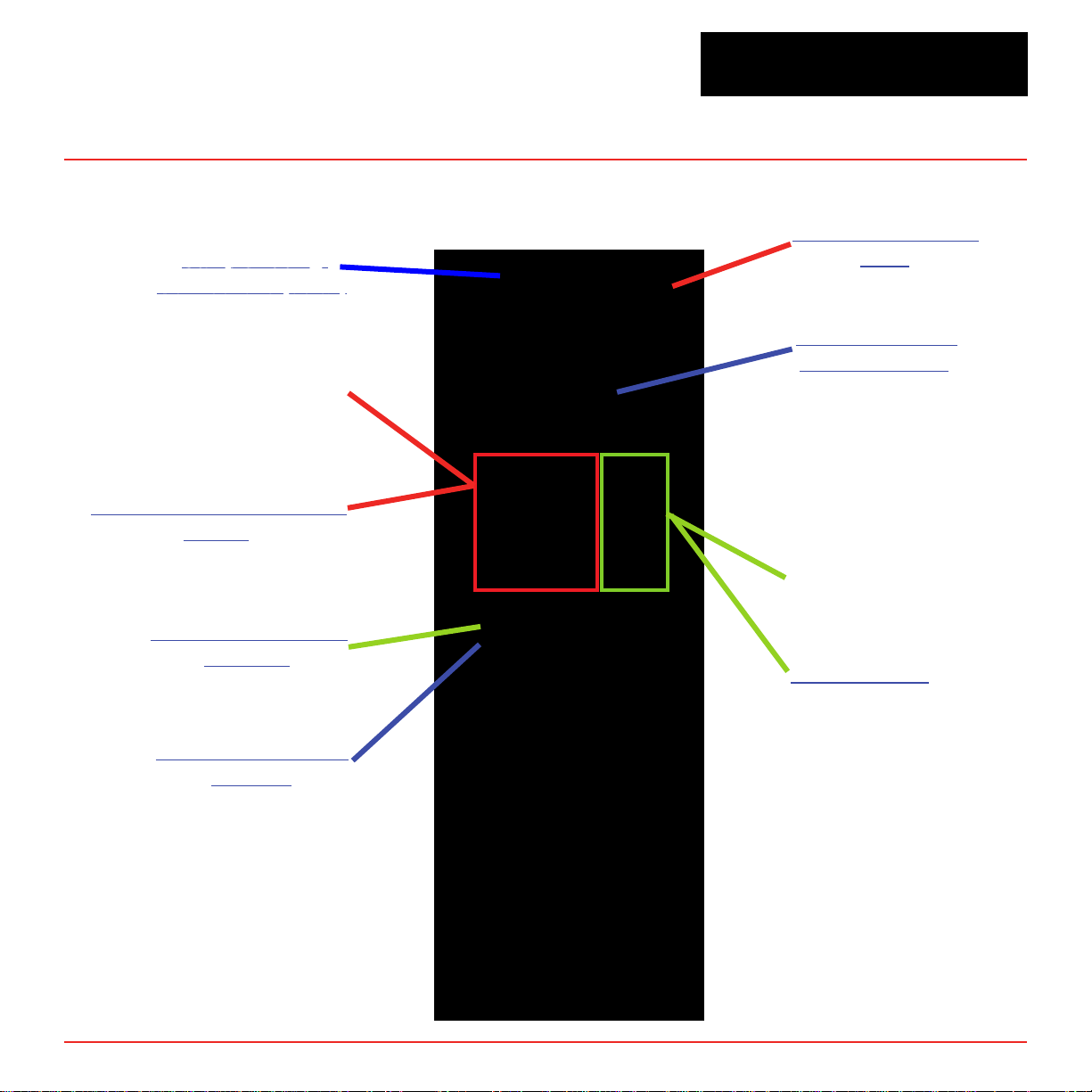
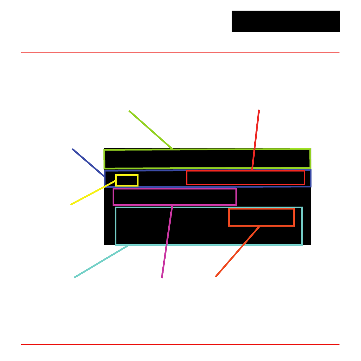
1.2.1 Vertex Front
Sample Tubing
Connections (detail)
Pyrolyzer Analyzer
Module Front Door Closed
(detail)
Analyzer Side Panel
(exterior)
Vertex
TM
72-Point Continuous Monitor
Exhaust and Wiring
Ports
System Controls
(behind screen)
Universal
®
Chemcassette
Analyzer
Analyzer Front
Analyzer Side Panel
(interior)
V ertex Technical Handbook
1-3
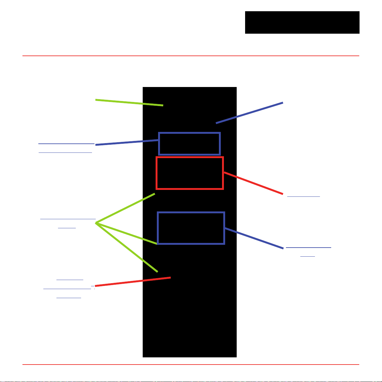
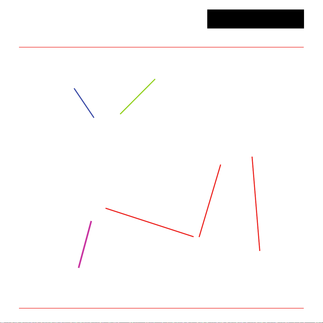
1.2.2 Vertex Back
Vertex
TM
72-Point Continuous Monitor
Relay Wire
Raceway
Data Acquisition
Computer (rear)
ChemCam USB
Hubs
Rear Main
Power
Main PLC
Relay Option
PLC
Back of
Chemcassette®
Module
V ertex Technical Handbook
1-4
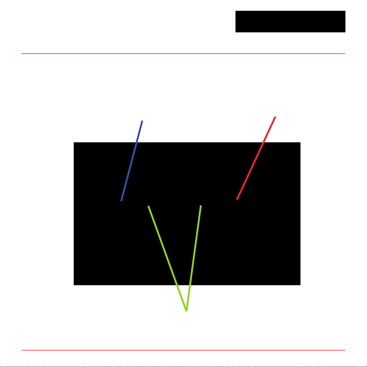
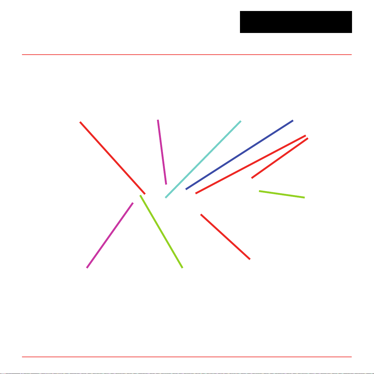
1.2.3 Exhaust and Wiring Ports
System Exhaust
0.5 in (12.7 mm)
tubing
Vertex
TM
72-Point Continuous Monitor
AC Input
0.75 in pipe thread
V ertex Technical Handbook
Alarm Wiring Conduit
Plates - 4 in (101.6 mm) x 2
1-5
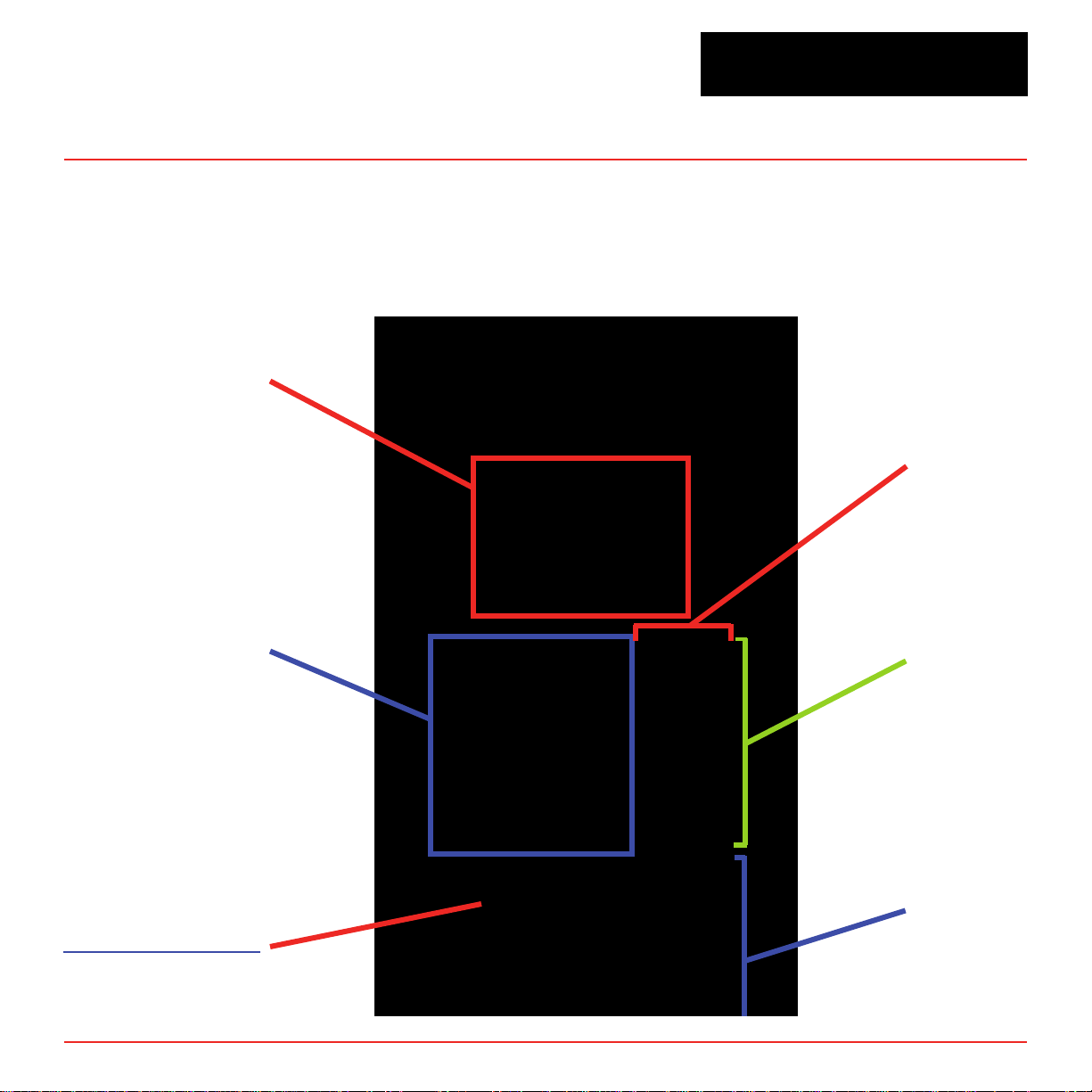
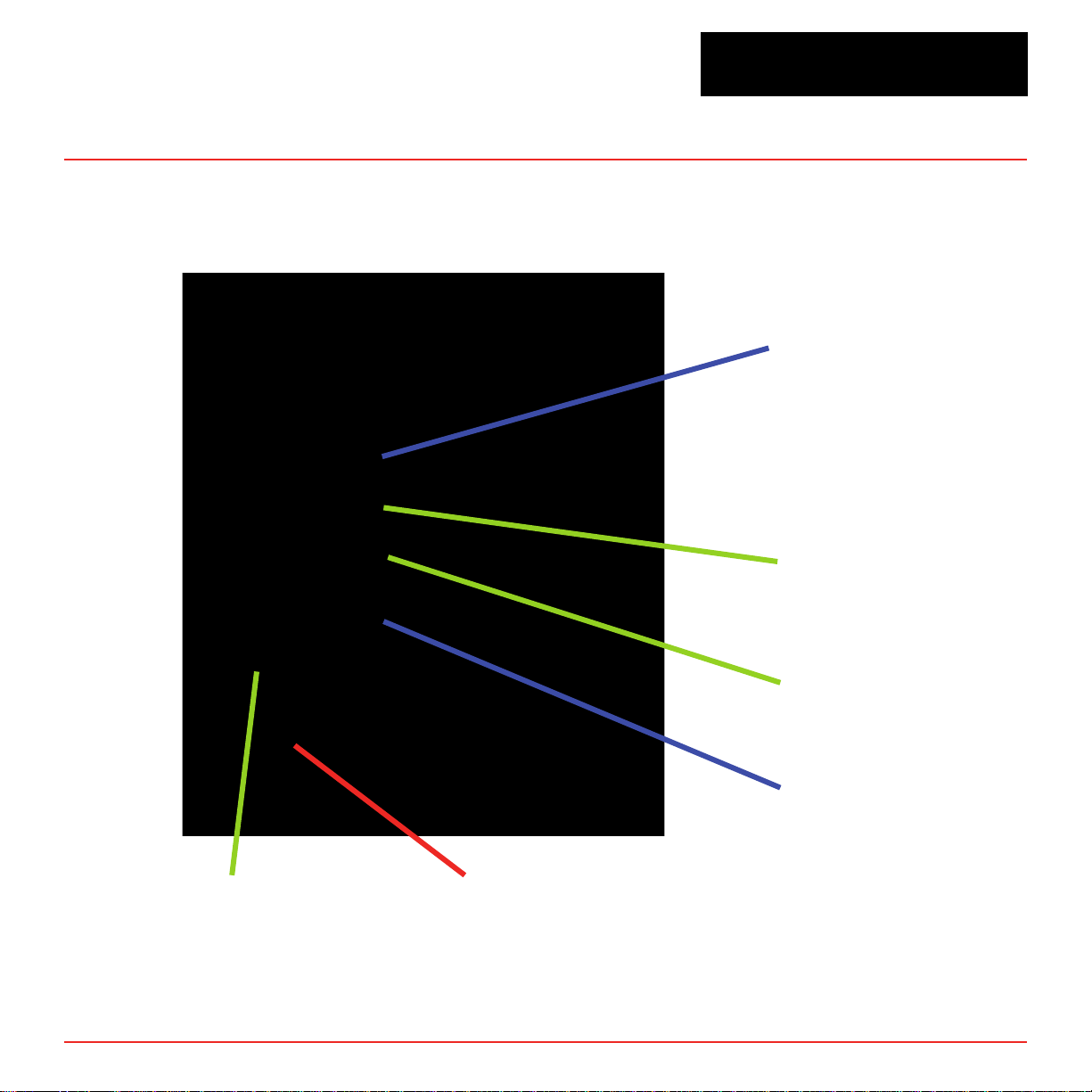
1.2.4 Module Front - Door Closed
Protective panel over
touch screen.
Open to use.
Vertex
TM
72-Point Continuous Monitor
Slot
Pyrolyzer Analyzer
Analyzer Status LED
V ertex Technical Handbook
Tier 1
Tier 2
1-6
1.2.5 Analyzer Side Panel (exterior)
Vertex
TM
72-Point Continuous Monitor
Slide Latch
Access Screws
V ertex Technical Handbook
1-7
1.2.6 Analyzer Side Panel (interior)
Vertex
TM
72-Point Continuous Monitor
Analyzer CPU
ChemCam Option
Sample Pressure
Transducers
Sample Flow
Transducers
Proportional Valve Filters
Sensor Interface PCB
V ertex Technical Handbook
1-8
Vertex
1.2.7 Sample Tubing Connections (detail)
TM
72-Point Continuous Monitor
Tier 1
Tier 2
Tier 3
4 - Port Manifold
for multiple gas sampling
See Section B.4, Nominal Transport Times
for tubing length limitations
Slot 1 Slot 2
Slot 3
Points - 1 thru 8
Left to Right
V ertex Technical Handbook
1-9
1.2.8 System Controls (behind screen)
Series 2 Units
Set Supply Vacuum
Power
Distribution
Module
Rack Power
Switch and
Circuit Breaker
Vertex
TM
72-Point Continuous Monitor
Analyzer DC and Pyrolyzer AC
Power Switches with Indicators
Data Acquisition
Computer (DAq)
V ertex Technical Handbook
24 VDC Power
Supplies
DVD
Drive
1-10
Hot Swap
Hard Drives
Analyzer
Communications
Hub (Ethernet)
Series 1 Units
Power
Distribution
Module
Rack Power
Switch and
Circuit Breaker
Analyzer
Communications
Hub (Ethernet)
Vertex
TM
72-Point Continuous Monitor
Analyzer DC and Pyrolyzer AC
Power Switches with Indicators
Data Acquisition
Computer (DAq)
V ertex Technical Handbook
24 VDC Power
Supplies
1-11
CD-RW
Drive
1.2.9 Analyzer Front
Analyzer Status LED
Vertex
Analyzer Window
TM
72-Point Continuous Monitor
Mounting Slot for Optional Keyboard
V ertex Technical Handbook
Product Label
location of
RoHS sticker
1-12
Vertex
1.2.10 Data Acquisition Computer (rear)
Series 2 Units
TM
72-Point Continuous Monitor
Serial Interface for
Touch Screen (COM 1)
Keyboard Connection
Note:
Touchscreen Video
Mouse Connection
LCD Video
(white cable)
Serial Connection to
the PLC, COM8
External Ethernet
Port
USB Ports
USB
Connection to
the Hosting
Device
This photo shows a typical port conguration. Port and slot
locations on your monitor may vary.
Caution:
Restrict access to the USB port to reduce the risk of malicious
software being introduced.
V ertex Technical Handbook
1-13

Series 1 Units
Vertex
TM
72-Point Continuous Monitor
Serial Interface for
Touch Screen (COM 1)
External Ethernet Network
Serial to PLC
(COM2)
Modem
Parallel Printer Port
Keyboard Connection
USB Port
Internal Ethernet
Network
LCD Video
Mouse Connection
Note:
This photo shows a typical port conguration.
Port and slot locations on your monitor may vary.
V ertex Technical Handbook
1-14

1.2.11 ChemCam USB Hub
ChemCam
USB Hubs
(3)
Vertex
TM
72-Point Continuous Monitor
V ertex Technical Handbook
1-15
1.2.12 Back of Chemcassette® Module
Vertex
TM
72-Point Continuous Monitor
ChemCam USB
Connection (option)
Analyzer
Communications
(Ethernet)
Circular Tubing
Harness
V ertex Technical Handbook
Cable Carrier
Analyzer 24V
Power Supply
Multifunction
Connector
Note:
Connection secured
by slide latch. Push up
to open. Push down to
close.
1-16
1.2.13 Main PLC
Vertex
TM
72-Point Continuous Monitor
DH485 Link
Coupler
Advanced Interface
Converter
PLC Power
Supply
Optional Relay
Modules
Connection to optional
4-20mA System
V ertex Technical Handbook
PLC
Processor
Module
1-17
DH485/RS232
Interface Module
Expansion slot
for optional
Communications
Interface
1.2.14 Relay Option PLC
Power Supply
Vertex
TM
72-Point Continuous Monitor
V ertex Technical Handbook
Relay Module (up to seven) cards
1-18
 Loading...