

Page 1
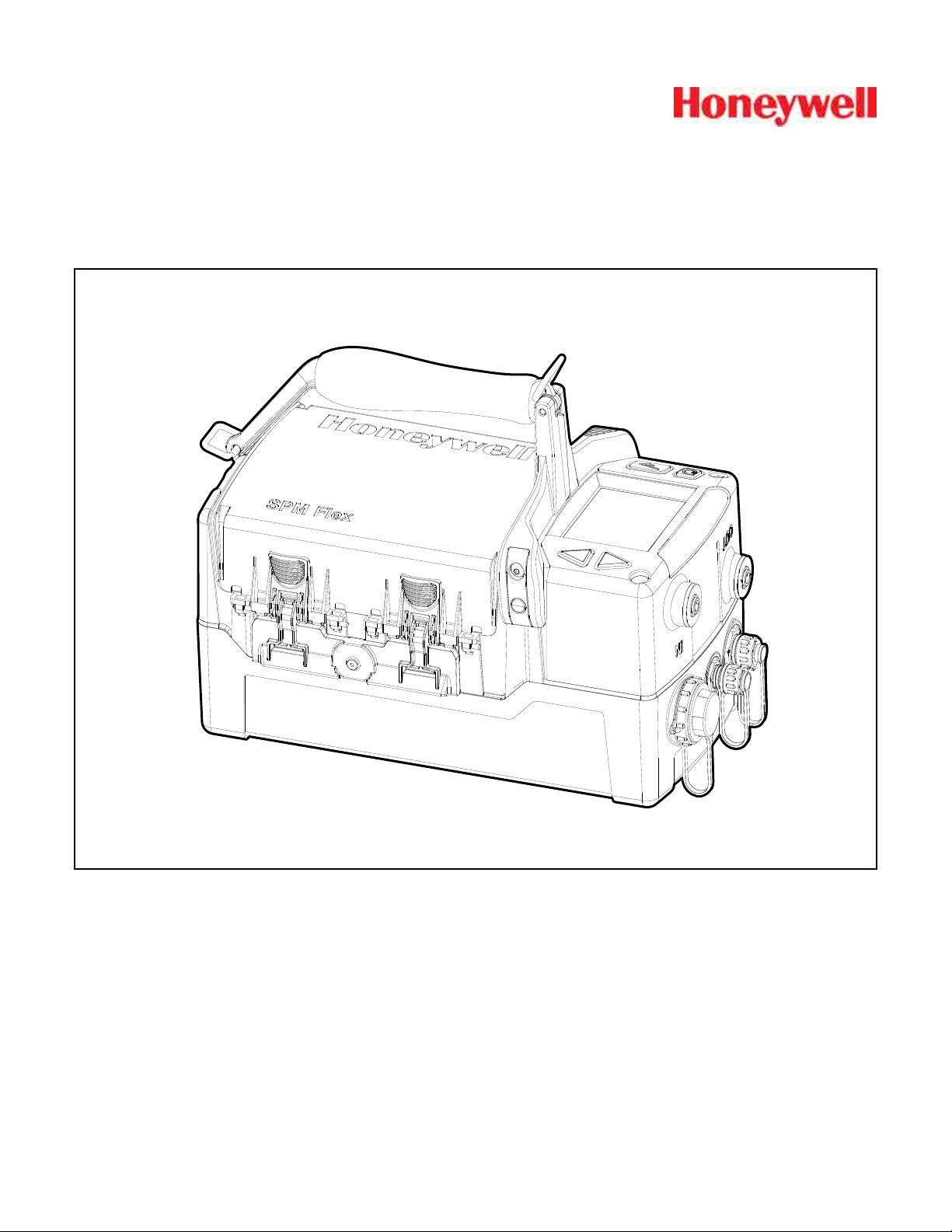
SPM Flex
Single Point Monitor Gas Detector
User’s Manual
Page 2

Page 3

SPM Flex Gas Detector
Introduction ����������������������������������������������������������������������������������������������������������������5
Safety Information ��������������������������������������������������������������������������������������������������6
Contact Information ������������������������������������������������������������������������������������������������ 7
Glossary ���������������������������������������������������������������������������������������������������������������������� 8
Product Overview ������������������������������������������������������������������������������������������������������� 9
Battery operation �������������������������������������������������������������������������������������������������� 10
The handle (portable model) ��������������������������������������������������������������������������������11
Opening the cover ������������������������������������������������������������������������������������������������11
Main power rocker switch ������������������������������������������������������������������������������������12
Turning the detector on and off ���������������������������������������������������������������������������� 13
Navigation �������������������������������������������������������������������������������������������������������������14
Menu Map �������������������������������������������������������������������������������������������������������������15
Wiring and tubing �����������������������������������������������������������������������������������������������������19
Typical fixed installation topologies ��������������������������������������������������������������������� 19
Wiring diagrams ���������������������������������������������������������������������������������������������������� 21
4-20 mA wiring ������������������������������������������������������������������������������������������������������ 22
Modbus register definitions ����������������������������������������������������������������������������������24
Setup ������������������������������������������������������������������������������������������������������������������������� 26
Installation drawing �����������������������������������������������������������������������������������������������26
Mounting options �������������������������������������������������������������������������������������������������� 26
Dimensions ������������������������������������������������������������������������������������������������������������27
Standard mounting bracket ����������������������������������������������������������������������������������28
Backward-compatible mounting bracket ������������������������������������������������������������29
In-line filters �����������������������������������������������������������������������������������������������������������30
Optional sampling wand ��������������������������������������������������������������������������������������� 30
Attaching the shoulder strap �������������������������������������������������������������������������������� 31
Operation ����������������������������������������������������������������������������������������������������������������� 32
Controls ����������������������������������������������������������������������������������������������������������������� 32
Setup menu ����������������������������������������������������������������������������������������������������������� 38
Troubleshooting �������������������������������������������������������������������������������������������������������� 42
Maintenance ������������������������������������������������������������������������������������������������������������� 46
Storing the detector ���������������������������������������������������������������������������������������������� 49
Recycling ���������������������������������������������������������������������������������������������������������������49
Storing Chemcassette
Labels ������������������������������������������������������������������������������������������������������������������������50
Detectable Gases ����������������������������������������������������������������������������������������������������� 51
Specifications ���������������������������������������������������������������������������������������������������������� 52
Accessories and Parts ���������������������������������������������������������������������������������������������53
Certifications ������������������������������������������������������������������������������������������������������������56
Warranties ����������������������������������������������������������������������������������������������������������������� 62
SPM Flex warranty ������������������������������������������������������������������������������������������������62
Chemcassette
®
cartridge warranty ���������������������������������������������������������������������� 62
Index �������������������������������������������������������������������������������������������������������������������������64
®
cartridges �����������������������������������������������������������������������49
3
Page 4

SPM Flex Gas Detector
4
Page 5

SPM Flex Gas Detector
Introduction
The SPM Flex gas detector is an extractive gas monitoring system that draws gas
®
samples locally or from a remote point to a Chemcassette
detection system� A wide range of toxic gas Chemcassette cartridges are available
that enable detection of gases used or generated in semiconductor manufacturing
and industrial environments�
The SPM Flex gas detector, available in wall mounted and portable versions,
locally displays gas concentration, alarm, fault and status information via its backlit
color LCD and LEDs� A simple to use 4-button keypad adjacent to the display
provides the ability to set-up, review, operate and make changes to the detector’s
configuration� The intuitive display and menu structure are designed to require
minimal training� The SPM Flex has a local audio alarm with user-configurable
output levels� The detector can be used both indoors and outdoors in a wide range
of weather conditions�
The detector has flexible power and communications capabilities� These include
3 on-board relays, 4-20 mA analog output and Modbus/TCP outputs for signal
and service connectivity� The gas detector is equipped with a USB port for
configuration-sharing firmware updates and data downloads� For web-enabled
devices, web pages are available via the Ethernet port�
tape-based optical gas
Standard operation conditions
The SPM Flex gas detector is designed for use in temperatures between 32ºF
and 104ºF (0ºC and 40ºC) and relative humidities between 0 and 100% (the
relative humidities are limited by tape and calibration)� The sample line will require
additional hardware to remove moisture in high relative humidity conditions where
condensing may occur (the sample must be non-condensing)� Dry conditions may
require humidification�
High-altitude applications
The SPM Flex pump is optimized for operation at altitudes between –1000 feet
(–305 meters) and 3000 ft� (945 m) above sea level� At altitudes above 3,000 ft�
(915 m), up to a maximum of 6,000 ft� (1,830 m), contact Honeywell Analytics for
calibration� (At 6,000 feet, pump capacity is reduced 18% and a flow-system
adjustment to the bypass valve is required� This must be performed by a Honeywell
Analytics certified technician� Contact Customer Service�)
5
Page 6
SPM Flex Gas Detector
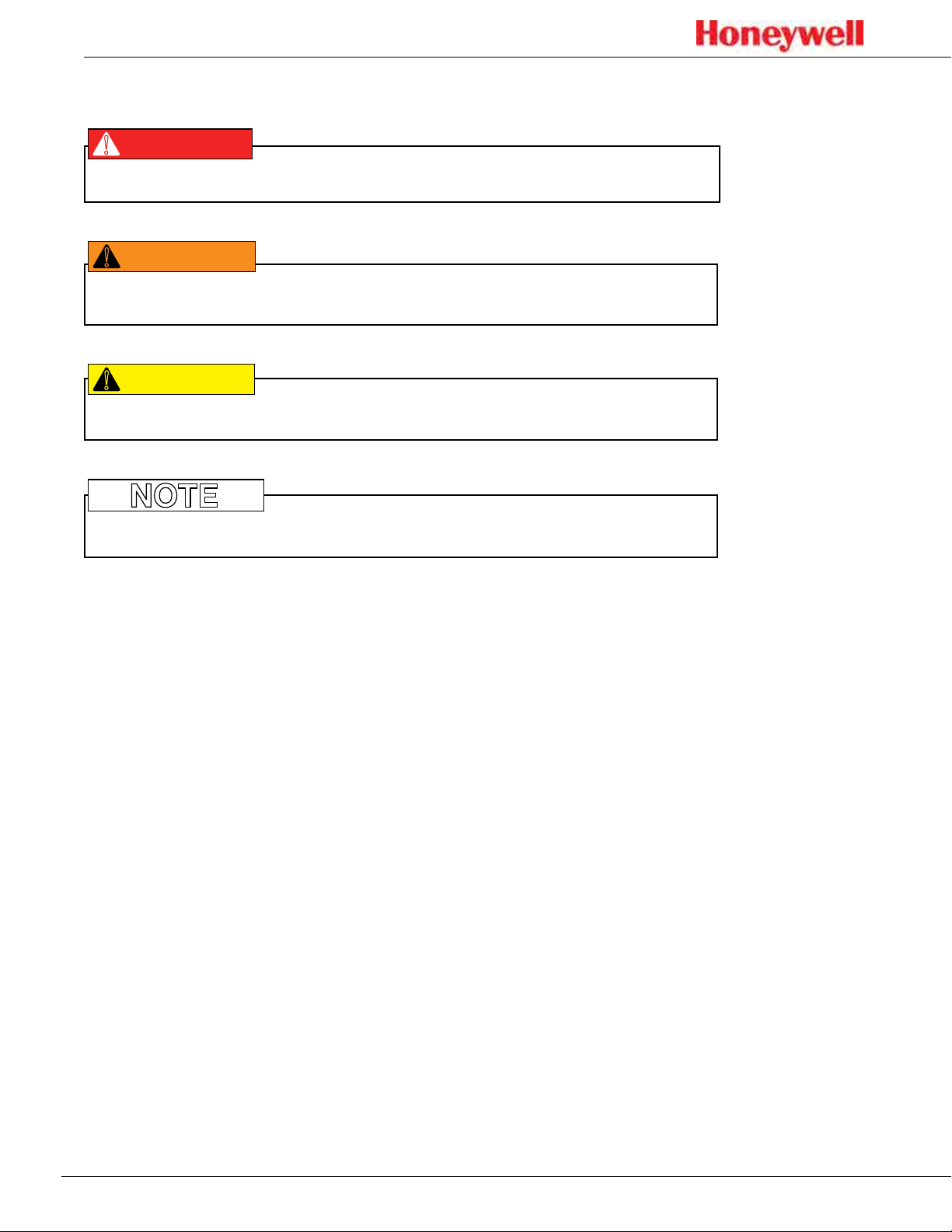
DANGER
!
Safety Information
Danger notices contain information that could prevent death or serious injury�
!
WARNING
Warnings contain information that could prevent injury or equipment damage�
!
CAUTION
Caution notices contain information that could prevent equipment damage�
NOTE
Notes contain helpful information�
6
Page 7

Contact Information
Find out more:
www�honeywellanalytics�com
Americas
Honeywell Analytics
405 Barclay Boulevard
Lincolnshire, IL 60069
Tel: +1 847 955 8200
Toll free: +1 800 538 0363
Fax: +1 847 955 8208
detectgas@honeywell�com
Europe, Middle East, and Africa
Life Safety Distribution AG
Javastrasse 2
8604 Hegnau
Switzerland
Tel: +41 (0)44 943 4300
Fax: +41 (0)44 943 4398
gasdetection@honeywell�com
SPM Flex Gas Detector
Asia Pacic
Honeywell Analytics Asia Pacic Co., Ltd.
#701 Kolon Science Valley (1)
43 Digital-Ro 34-Gil, Guro-Gu
Seoul, 152-729
Korea
Tel: +82 2 6909 0321
VOIP: +8 5401 0321
analytics�ap@honeywell�com
Technical Services
ha�global�service@honeywell�com
www�honeywell�com
7
Page 8
SPM Flex Gas Detector
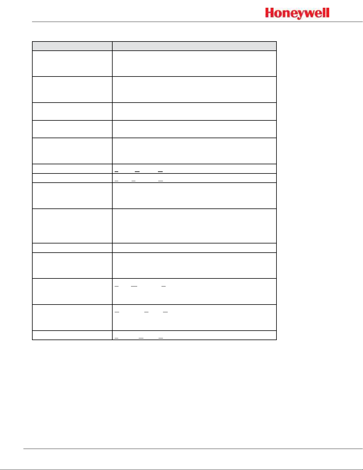
Glossary
Term Description
An analog communication method using a current
4-20 mA loop
®
Chemcassette
Ethernet
In monitor
Latching alarm or fault
LCD
LED
Modbus TCP
Non-latching alarm or
fault
Out of monitor The detector is on but idle
Relay
TWA
USB
VDC
cartridge
loop to indicate concentration readings and fault
status�
An easy-to-install case that carries Honeywell’s
Chemcassette tape� Cartridges are specific to
different gas types/families�
Commonly used network technology for wired Local
Area Networks�
The unit is actively monitoring the specified gas or
family of gases
When configured, the SPM Flex will hold the alarm or
fault status active until the user performs an alarm/
fault reset�
Liquid Crystal Display
Light Emitting Diode
Communications protocol running over Ethernet that
is commonly used for communicating with industrial
devices�
An alert in which the SPM Flex will reset
automatically when the condition is no longer
present (i�e�, the detector does not have to be reset
by the user)�
An electrical-operation output switch that can be
used to indicate the presence of alarm and fault
conditions�
Time Weighted Average, the average exposure to a
harmful gas, usually calculated over a period of eight
hours (a the typical workday)�
Universal Serial Bus is an industry standard
communications protocol and bus that is commonly
available on personal computers�
Volts of Direct Current
8
Page 9

SPM Flex Gas Detector
WARNING
!
Product Overview
The SPM Flex gas detector is available in two configurations, portable and fixed�
The portable model is equipped with a handle assembly and a shoulder strap�
The fixed unit is supplied with a mounting bracket� If replacing an old SPM
detector, a retrofit bracket is available (these are shown on pages 28 and 29)�
1
All units are supplied with a power adaptor
manual, and a printed quick start guide�
Operate and service the SPM Flex gas detector only as specified in this manual
and the accompanying quick start guide� Failure to do so may impair the
protection provided by the detector and may also void the warranty�
Initial setup
Prior to use, the detector requires some minimal setup:
• Unpack the unit (save the packaging to re-use for service requests)�
• Read the quick start guide and this manual�
• Remove the paper optics card from the gate
and cable, a CD containing the user
Portable detectors
• Connect the power adaptor (in a dry, indoor location)
• Charge for at least 4 hours (the detector can be used while being charged)
• Open the detector’s cover
• Remove the rocker switch cover
• Turn the rocker switch to the on position
• Replace the rocker switch cover
• Load a chemcassette
• Configure the detector and begin to monitor (see pages 15-16 for basic
display usage)
• See detailed Operation (pages 32-41) and Optional accessories (pages 53-55)
Fixed detectors
• Install the wall-mount bracket and mount the detector to it (see pages 28-29)
• Wire in accordance with local electrical codes utilizing a trained electrician
(see pages 19-25)
• Input
• Honeywell-supplied power adaptor (indoor, dry location use only) or
• 24 VDC power supply
• Signal (as desired)
• 4-20 mA
• Relays
• Ethernet
• Open the detector’s cover
• Remove the rocker switch cover
• Turn the rocker switch to the on position
• Replace the rocker switch cover
• Load a Chemcassette cartridge
1 FSP Group Model FSP135-AAAN rated 1 5.62A / 24V (UL Listed QQGQ (E190414))
9
Page 10
SPM Flex Gas Detector
• Configure the detector and begin to monitor (see pages 15-16 for basic
display usage)
• See detailed Operation (pages 32-41) and Optional accessories (pages 53-55)
Additional accessories
• External dust filters (required on inlet) and/or tubing (can be used to reduce
contamination as well as noise)
• Sampling wand
• Mating signal connectors for fixed installations
Battery operation
The SPM Flex gas detector is supplied with a power supply/charger than can
connect the detector’s power connection and a standard wall outlet� (Ensure that
the correct power cable has been ordered for local operation�) The power supply/
charger is designed for indoor, dry-location use only� The lithium-ion battery pack
provides continuous operation of 6+ hours, depending on sampling conditions
and unit configuration� The battery’s charge time is typically 4 hours� The
detector can be operated while its battery is being charged (this may increase
the charge time)� The battery is designed for 1000 charge cycles� Honeywell
Analytics recommends keeping the detector connected to the power supply/
charger when not in use to keep the battery fully charged�
!
WARNING
• The battery is not field-replaceable� Return the unit to Honeywell Analytics
if a battery replacement is necessary�
• Risk of fire and burns� Do not open, crush, heat above 140ºF (60ºC), or
incinerate the battery� Follow manufacturer’s instructions�
How to extend battery life
Power consumption is optimized to extend battery life when not in monitor mode�
In addition, the unit should not be exposed to extreme temperatures which
shortens battery life� The time before recharging is required can be extended by
taking the detector out of monitor mode when it is not in use�
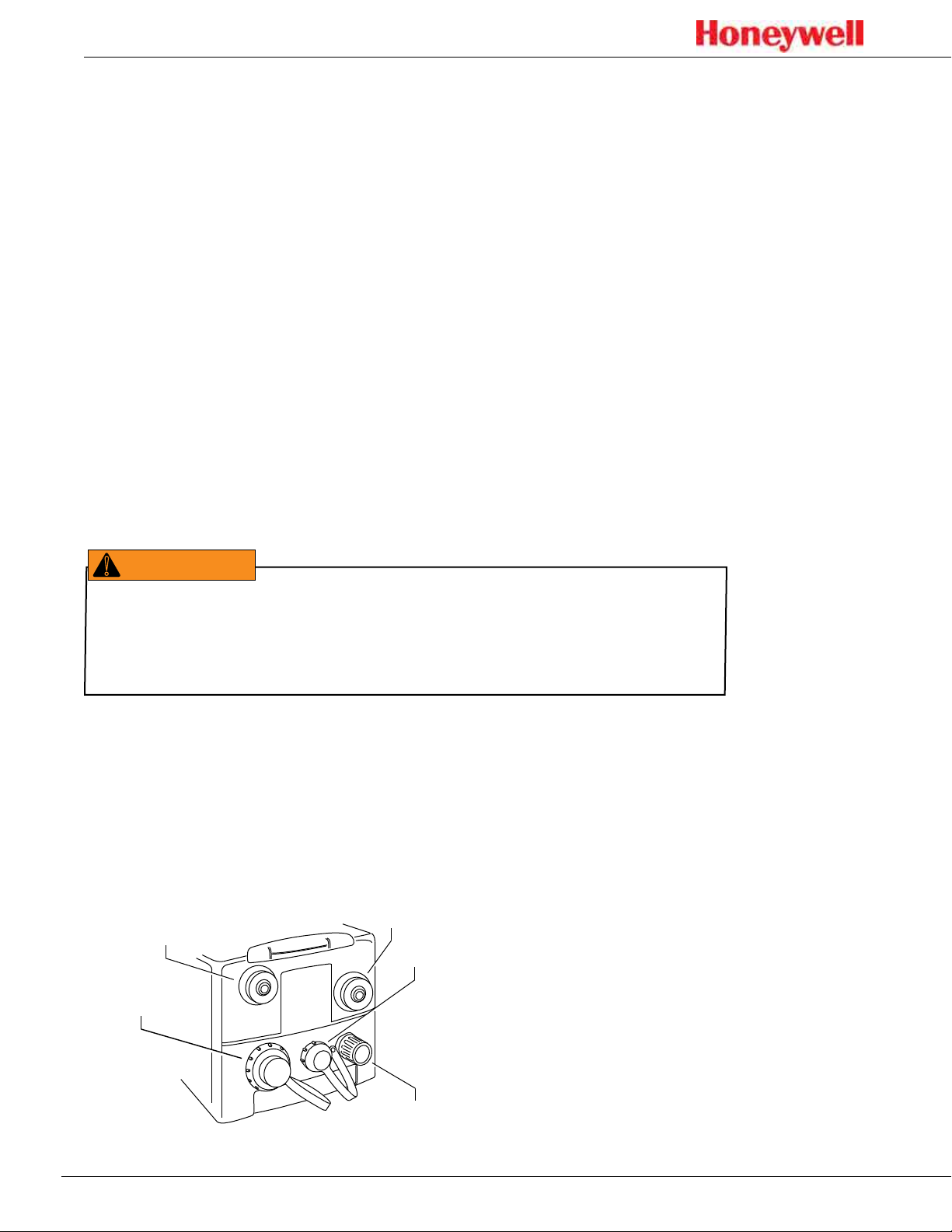
The ports of a typical installation is shown in the figure below�
Exhaust out port
Sample in port
Power
Ethernet
Figure 1. terminals and ports
10
Relays or 4-20 mA
Page 11
SPM Flex Gas Detector
The handle (portable model)
The detector can be conveniently carried with the optional handle, which is
mounted onto the cover at three locations� If necessary, the handle can be
removed by the user by removing two bolts� All of the detector’s functions can be
performed with the handle attached� The handle swings out of the way for access
to the Chemcassette cartridge area�
Opening the cover
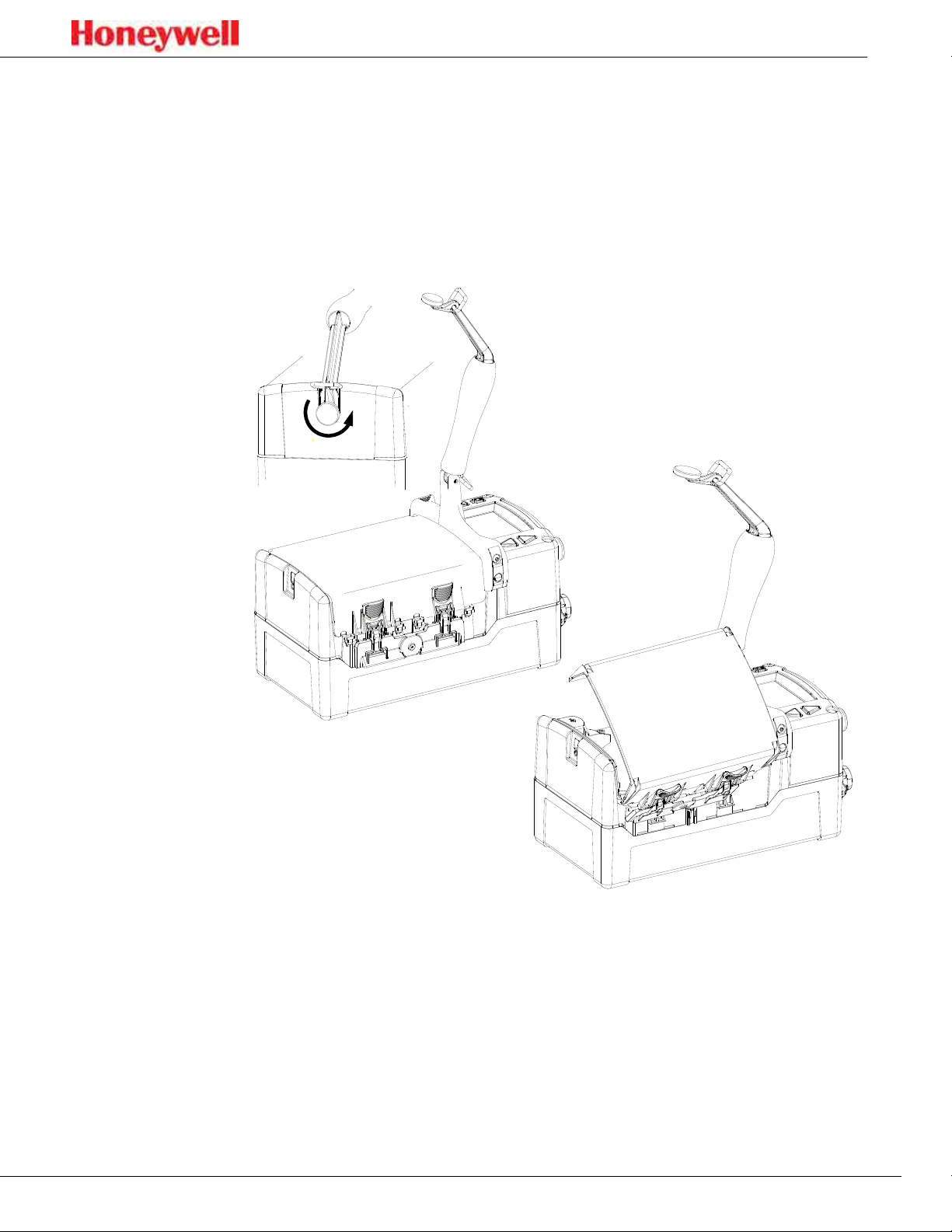
Figure 2. Opening the detector cover
Release the cover by first unscrewing the handle pin� Pivot the handle up as
shown in the illustration and push down the four latches (two on each side)�
The detector cover will then be free to swing open, allowing a Chemcassette
cartridge to be inserted or replaced, the power switch to be turned on or off, or
the USB data port to be accessed�
11
Page 12
SPM Flex Gas Detector
Main power rocker switch
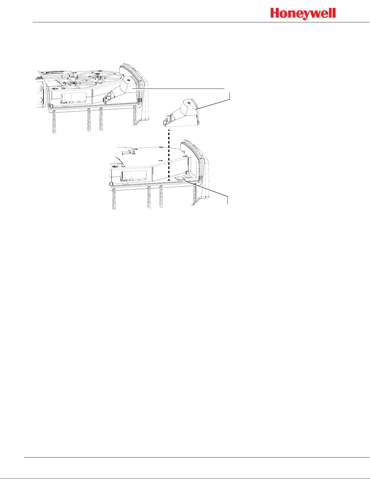
Rocker switch cover
Main power rocker switch
Figure 3. SPM Flex main power rocker switch
After the detector’s cover is open, use a Phillips screwdriver to remove the rocker switch
cover� Turn the main power rocker switch to the on position and replace the rocker
switch cover�
The detector can now be turned on�
12
Page 13
SPM Flex Gas Detector
Turning the detector on and off
Press and hold the Power/Cancel button until the green LED begins blinking� The
detector will begin a startup sequence that lasts about 30 seconds�
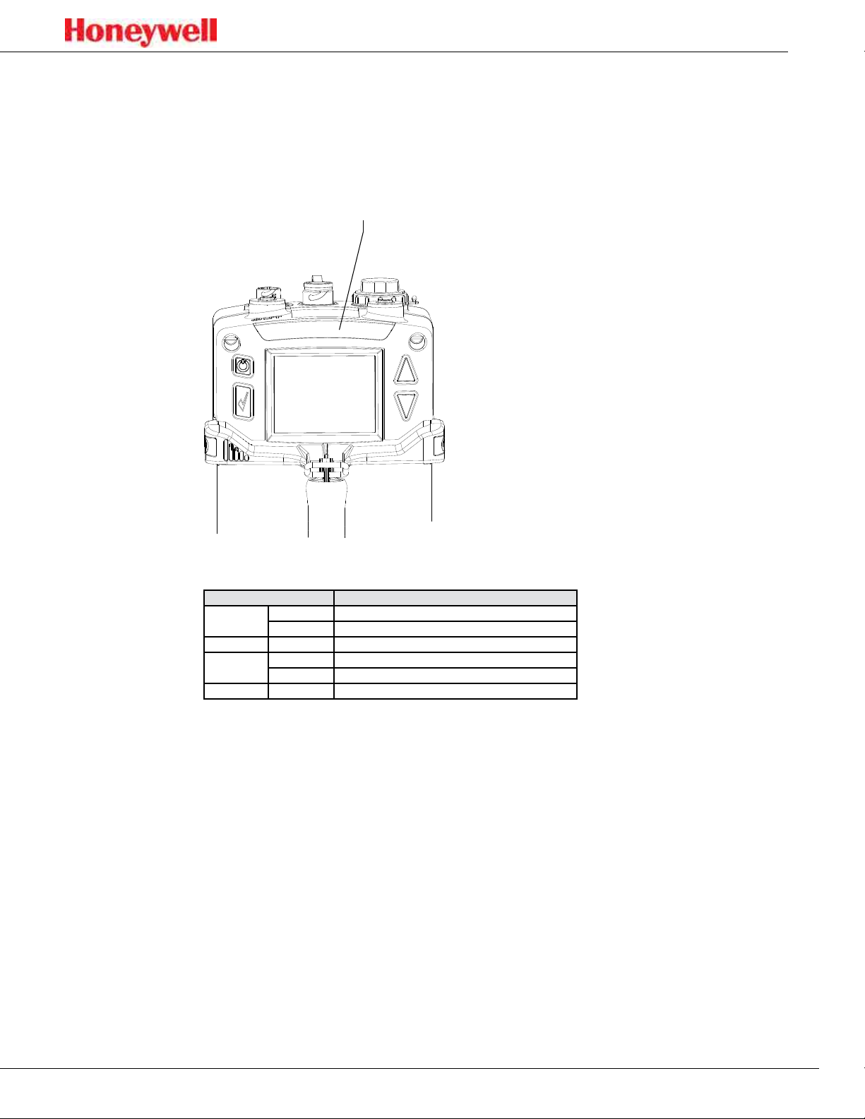
The four LEDs provide at-a-glance information about the current state of the
detector:
LEDs (red, green, yellow, blue)
Figure 4. SPM Flex LEDs
LED Description
Red
Green blinking The detector is active
Yellow
Blue solid Connected to external power
solid Alarm 1
blinking Alarm 2
solid Maintenance fault
blinking Instrument fault
To turn the detector off, press and hold the Power/Cancel button for 5 seconds or
select “Power Off” from the menu�
13
Page 14
SPM Flex Gas Detector
Navigation
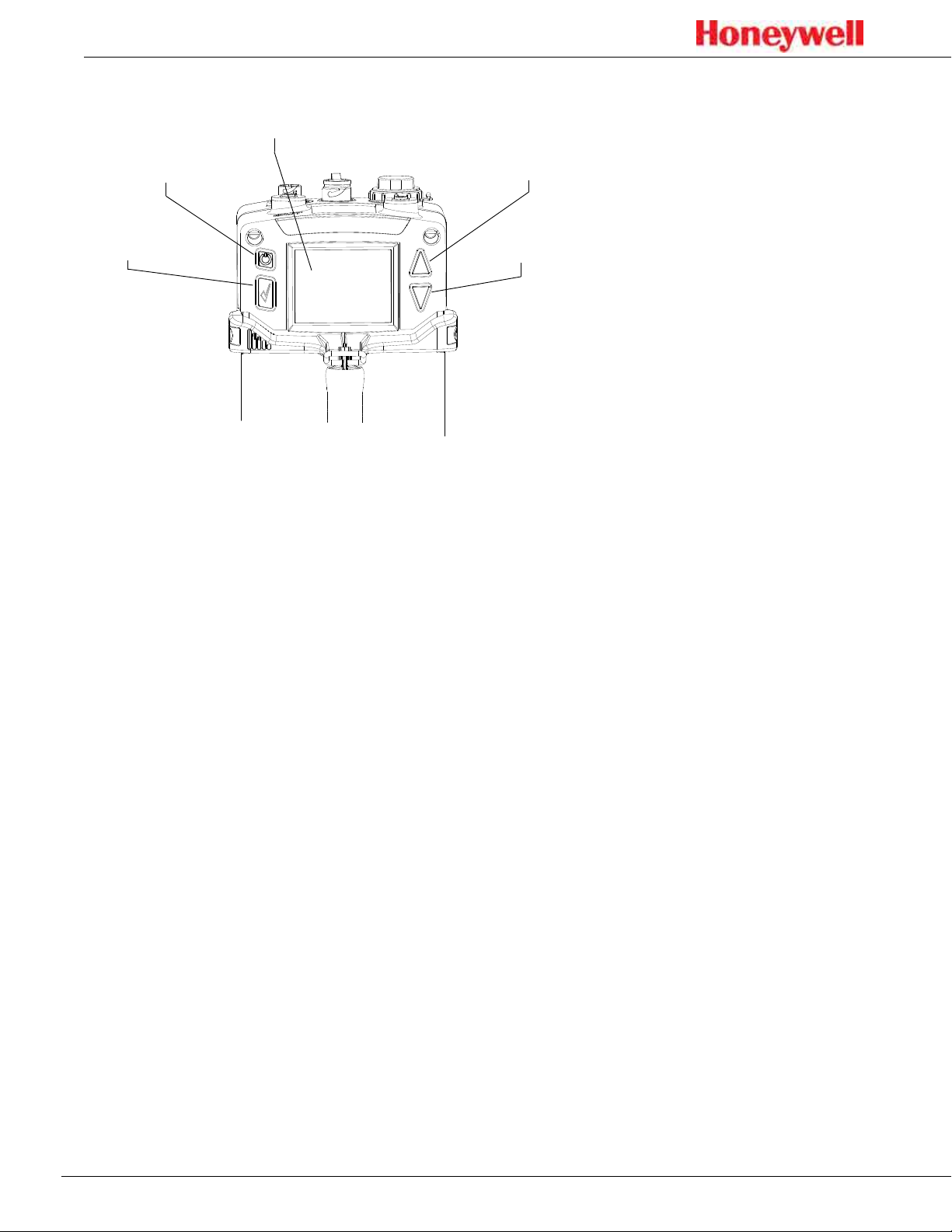
Display
Power/Cancel
Accept/Select
Figure 5. SPM Flex controls
Up arrow
Down arrow
All SPM Flex menus are navigated by the four buttons shown in Figure 5�
Pressing either of the arrows or the Accept/Select button will access the menu
from the main display screen� The arrows also are used to scroll up and down
through lists of options� The Accept/Select button is used to initiate a highlighted
option� During navigation, the Power/Cancel button will cancel a command or,
when pressed for more than 3 seconds, it will exit to the main display�
14
Page 15
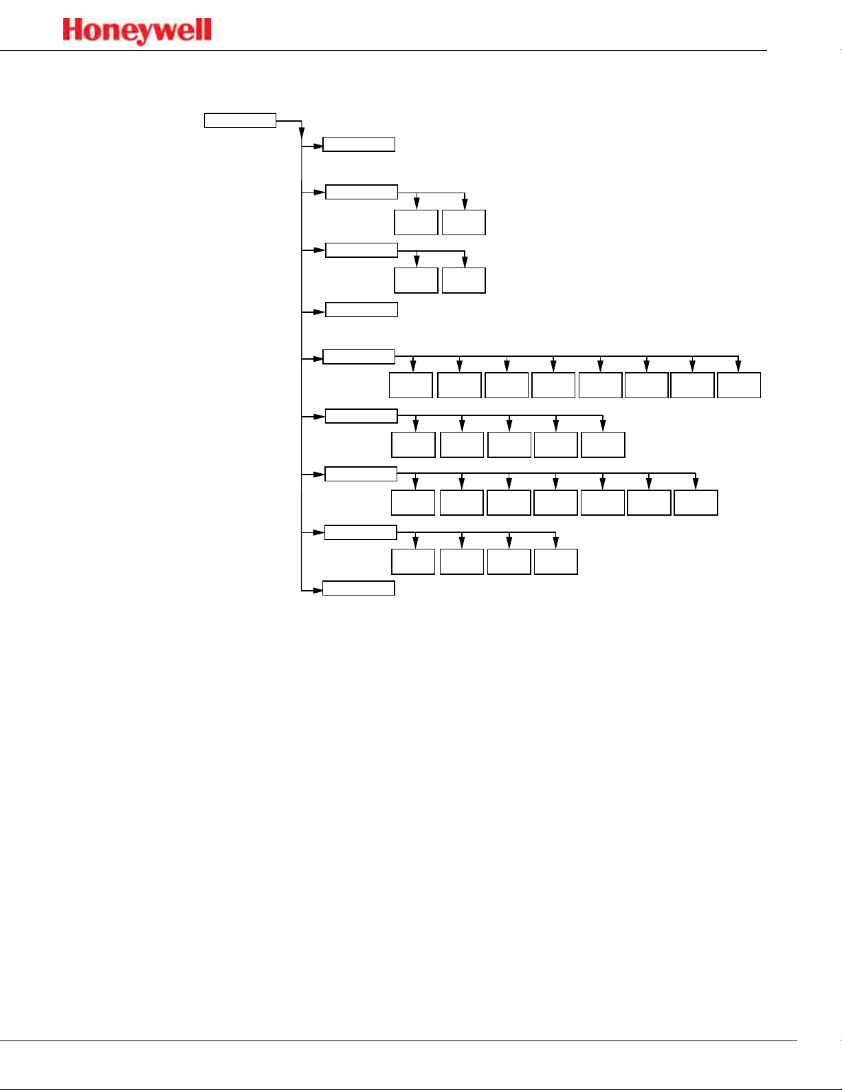
Menu Map
Main Menu
SPM Flex Gas Detector
Login/Logout
Reset Alarms & Faults
Monitor Mode
Change Chemcassette
Review Mode
Maintenance
Setup
Test
Power Off
Reset all
Enter
monitor mode
Event
History
Inhibit
Summary
General
Optics
Verification
Silence
audio alarm
Out of
monitor mode
Chem-
cassette
4-20 mA
Current Loop
Monitoring Latching
Simulate
Gas
Settings
Flow Characterization
Force
Relay
Gate
Force
4-20 mA
Additional
Status
Update
Program
Network
Open/Close
Outputs Network
Output
State
Security
Configuration
Manager
SoftwareTrend/Plot
The SPM Flex detector’s menus are easily navigated� As an example, this is how
a user could review the detector’s gas settings when starting from the In Monitor
screen:
1� Press the Up Arrow > to return to the Main Menu�
2� Press the Down Arrow 4 times to highlight the Review Mode option�
3� Press the Accept/Select button to enter Review Mode�
4� Press the Up Arrow or Down Arrow until the Gas settings option is
highlighted�
5� Press the Accept/Select button to display the Gas Summary�
To return to the detector to the In Monitor display, press the Power/Cancel button
three times to back out of the Main Menu options�
15
Page 16
SPM Flex Gas Detector
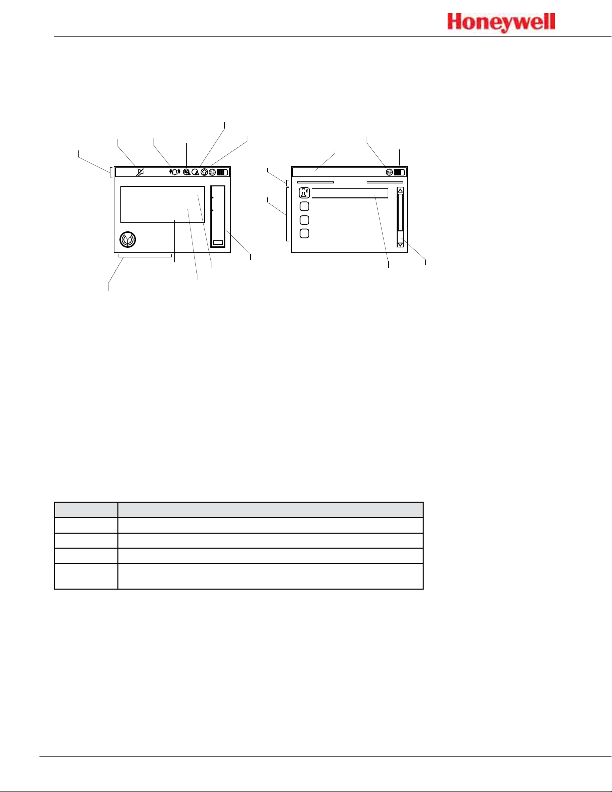
The display
Figure 6 shows the elements of the display that will be seen in various situations�
Status bar
Mute
Alarm 1/
Alarm 2/
Inhibit
indicator
Instrument
Maintenance
Fault
Fault
Concentration
trend
indicator
Menu
Clock
Monitor
mode
Indicator
Battery
indicator
title
15:
42:
01
0
123
.
-
H2S
Hydrogen Sulfide
In monitor
Gas name
Gas concentration
2
Menu
ppm
Units
5.678
1.234
options
Bar graph
w/upper, lower
alarm limits
42:
01
15:
Login / Logout
Reset alarms/faults
Monitor mode
Change Chemcassette
Main menu
Highlighted
Scroll bar
option
Monitor mode indicator
Figure 6. Elements of typical SPM Flex detector displays
The bar graph on the right shows the current concentration relative to the Alarm
1 and Alarm 2 setpoints� (The bar’s range is relative to the alarm levels, not to the
full scale of the selected gas)�
The color of the status bar changes according to the system status (green = OK/
in monitor, yellow = fault, red = alarm, blue = Out of Monitor mode)�
Display and navigation
Under normal operation the LCD and LED display system status, gas
concentrations, and alarms� In set-up, review, calibration, and test modes, the
LCD shows the relevant menu options and system status bar� The interface is
navigated using the four buttons:
Control Function
Up arrow Scroll up through lists of options
Down arrow Scroll down through lists of options
Accept/Select Accept or select a highlighted option
Power/Cancel
Power/Cancel will turn the unit on if it’s in the off state, will exit back to the previous menu level, and will
enter Reset mode (quick press), or Power Off mode (long press and hold) from the main display.
In the main display mode, the display shows the current gas name and
concentration, the monitoring states and faults and/or alarm status, if applicable�
16
Page 17
SPM Flex Gas Detector
Loading a Chemcassette cartridge
The Chemcassette cartridge door must be closed before putting the detector
into monitor mode (this holds the Chemcassette cartridge in place)� The detector
must be taken out of monitor mode before opening the door�
NOTE
Chemcassette cartridges must be stored according to the manufacturer’s
guidelines when not in use�
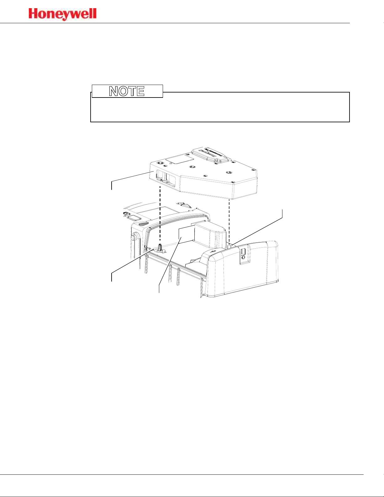
Chemcassette
cartridge
Take-up spindle
Supply spindle
Optics gate card
Figure 7. The optics gate card and Chemcassette cartridge
1� If the detector’s handle is installed, release it by unscrewing the thumbscrew�
For fixed installations, skip to Step 3�
2� Tilt the handle up as far as possible�
3� Unfasten the latches on the sides of the detector (two on each side) that
secure the Chemcassette cartridge access cover�
4� The detector has slotted hinges� Lift up the cover slightly and then open it all
the way to the right�
5� Select the Change Chemcassette menu option and follow the on screen
instructions�
6� If required, remove the old Chemcassette cartridge� When prompted, snap
the new Chemcassette cartridge into place. It will t in only one orientation.
The takeup spindle will “utter” back and forth to allow easy installation.
7� To close the cover, position it over the base and press so that it contacts the
gasket uniformly�
8� Close the latches on the sides of the detector to secure the cover�
17
Page 18

SPM Flex Gas Detector
If there is an error (i�e�, the same cartridge was reinserted, the new cartridge has
expired, or an unqualified user is attempting to insert a cartridge that detects
a different gas than the last one), an error message will be displayed and the
installation will be canceled� If the installation is successful, a summary of the
current configuration will be displayed and the user can then choose whether to
enter Monitor Mode or exit the Change Chemcassette Mode out of monitor�
Removing a Chemcassette cartridge
1� Navigate to Maintenance > Open/Close gate�
2� Select “Open Gate�”
3� Remove the cartridge�
4� Select “Close Gate�”
Changing the selected gas
1� While out of monitor mode, navigate to Set-up > Monitoring > Gas�
2� Select “Current gas” and pick the desired gas from the selection box
3� Select “Save�”
Entering monitor mode
From the main menu, navigate to the “Monitor Mode” option and select “Enter
monitor mode�”
1� If a Chemcassette cartridge has been installed, the detector will enter Monitor
Mode�
2� If a Chemcassette cartridge has not been installed, a user with the necessary
passcode can inititate the Chemcassette wizard� Otherwise, the detector will
not enter monitor mode�
18
Page 19
SPM Flex Gas Detector
Wiring and tubing
Typical fixed installation topologies
The SPM Flex gas detector has flexible installation options to allow the user to
select the one most suitable for a specific application� The detector is supplied
with weather-sealed connectors for both power and Ethernet, and with a third
port sealed� A third connector for communications is installed (for relays or
4-20 mA), or any of the ports can be replaced with appropriate connections in
accordance with local codes (allowing the user to wire directly to the terminal
block)� Install the detector near a dedicated circuit breaker�
!
CAUTION
• The safety of any system incorporating the SPM Flex gas detector is the
responsibility of the assembler of the system�
• Position a permanently-installed SPM Flex gas detector so that it does not
interfere with access to the dedicated circuit breaker�
Electrical connection is made via conduit directly to ports or via the connector
(see Figure 1 on page 10)� The terminals used are suitable for conductors of 24
to 14 AWG (0�5 to 1�8mm Dia�)� The use of 16 AWG (1�5 mm dia�) conductors is
recommended�
!
CAUTION
Use the supplied power adaptor/connector only� (The adaptor is rated for
indoor use only�)
19
Page 20
SPM Flex Gas Detector
Ethernet connector
P8
P9
+
24 VDC
-
Fault
NO
NC
COM
COM
Relay 2
NC
Relay 1
NO
NC
COM
+
-
4-20 mA
NO
4-20 mA
connections
Input power
connections
Relay
connections
top of
detector
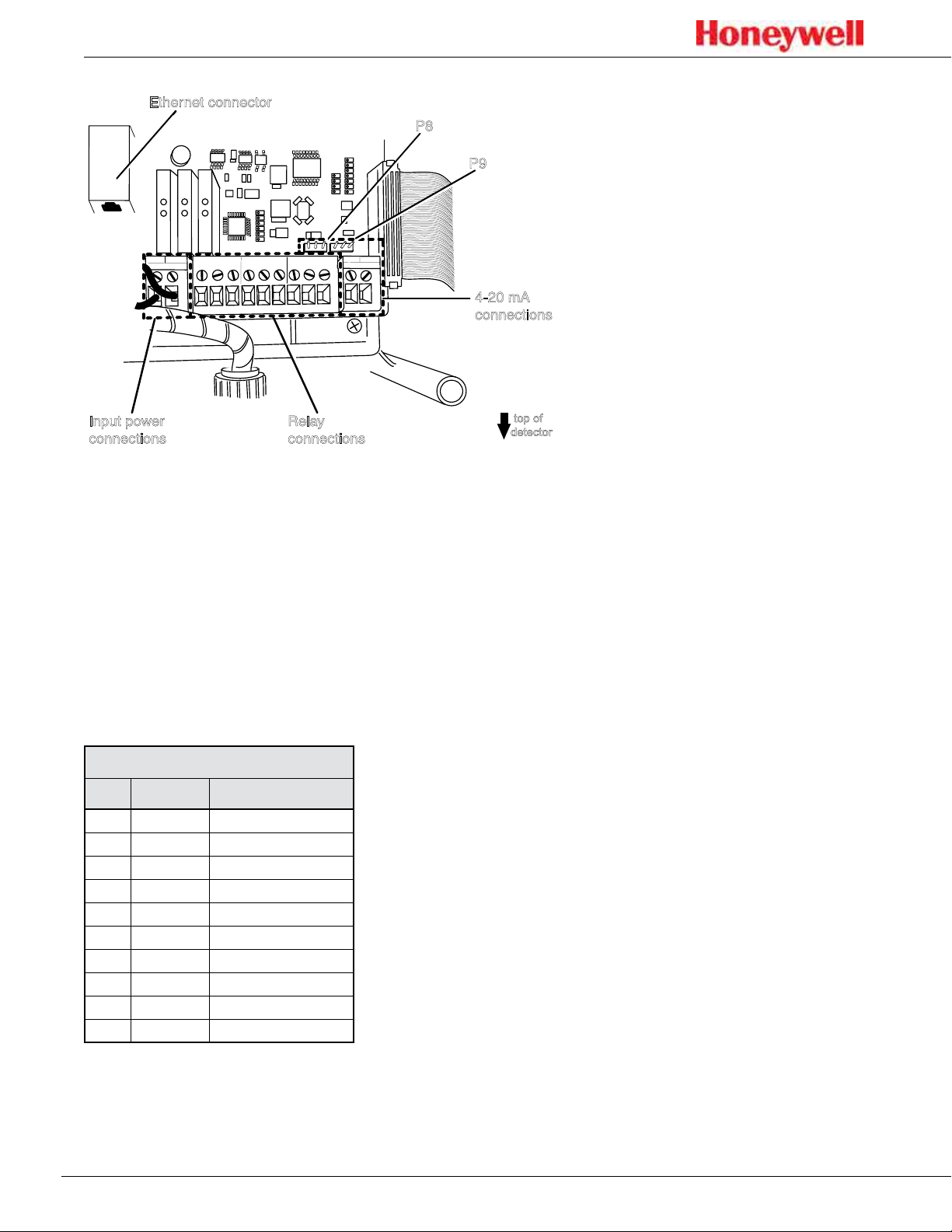
Figure 8. SPM Flex connections
Terminal Module
The terminal module is located on the main PCB inside the gas detector� All
power, relay, and 4-20 mA connections to SPM Flex are made via this module�
Wire entry to the terminal module area is via the cable entry/conduit entry located
at the top of the detector�
This table shows the default wiring configuration for the communication
connector when installed by Honeywell Analytics� The relays are labeled for the
factory default but the configuration can be modified to have a single alarm and
separate faults�
Relay Terminal Connections
No. Color Assign to Relay
1 Brown
2 Red
3 Orange
4 Yellow
5 Green
6 Blue
7 Purple
8 Gray
9 White
10 Black
Alarm2 COM
Alarm2 NO
NC
Alarm1 COM
Alarm1 NO
NC
Fault COM
Fault NO
NC
NC
For 4-20 mA wiring, wires 1 through 8 would be disconnected and wires 9 and 10
would be used� Do not run 4-20 mA signals and relay signals in the same cable
bundle�
20
Page 21
Wiring diagrams
SPM Flex Gas Detector
Controller
R
L
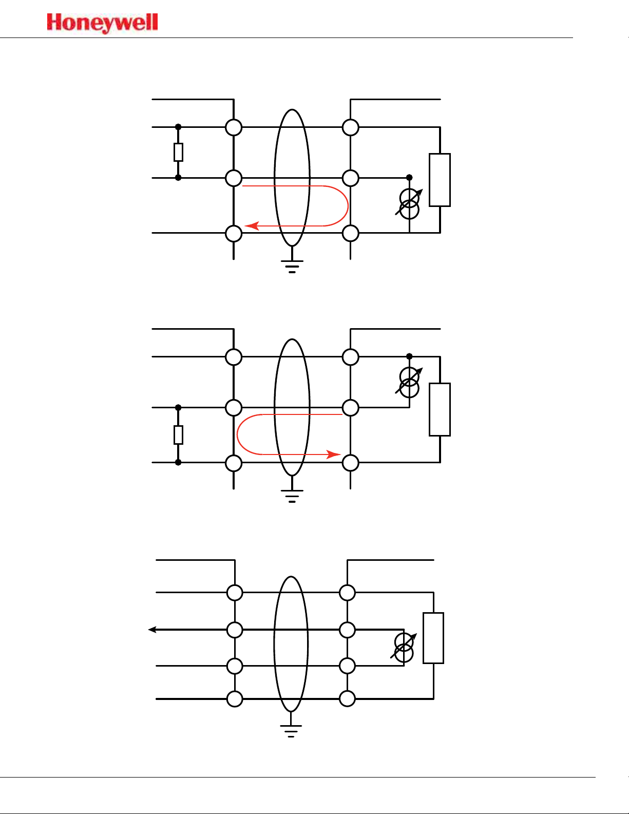
Figure 9.
Controller
+VE
Signal
-VE
4-20 mA sink wiring diagram
+VE
1
2
3
1
SPM Flex
24V+
4-20 mA+
Current
Flow
24V-
SPM Flex
24V+
R
L
Figure 10.
Controller
Signal
-VE
4-20 mA source wiring diagram
+V1
+V2
-V2
-V1
2
Current
Flow
3
4-20 mA -
24V-
SPM Flex
24V+
4-20 mA+
4-20 mA-
24V-
Figure 11.
4-20 mA isolated wiring diagram
21
Page 22
SPM Flex Gas Detector
4-20 mA wiring
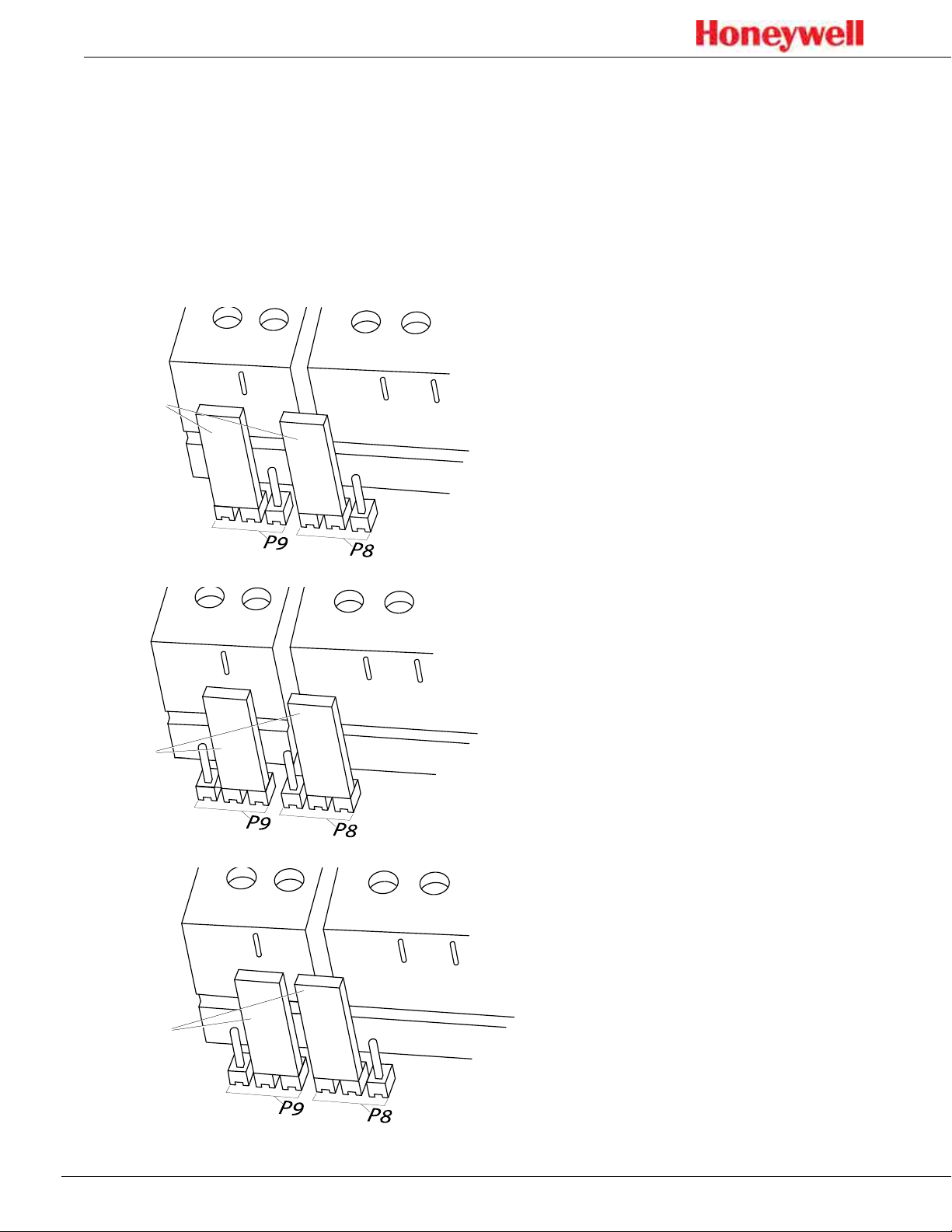
4-20 mA output is a three-wire connection that is configurable as sink, source, or
isolated, as shown in these following figures� Use an Allen wrench to remove the
wiring cover for access to the terminals� There must be a 200-600-ohm load on
the 4-20 mA line�
To ensure adequate resolution to overcome tolerance in the 4-20 mA reading, set
the full scale at an appropriate level� The SPM Flex issues a fault if the measured
4-20 mA reading is more than 0�8 mA (5% full scale) off from the expected drive
value�
jumpers
Figure 12. 4-20 mA sink conguration
jumpers
Figure 13. 4-20 mA source conguration
jumpers
Figure 14. 4-20 mA isolated conguration
22
Page 23
SPM Flex Gas Detector
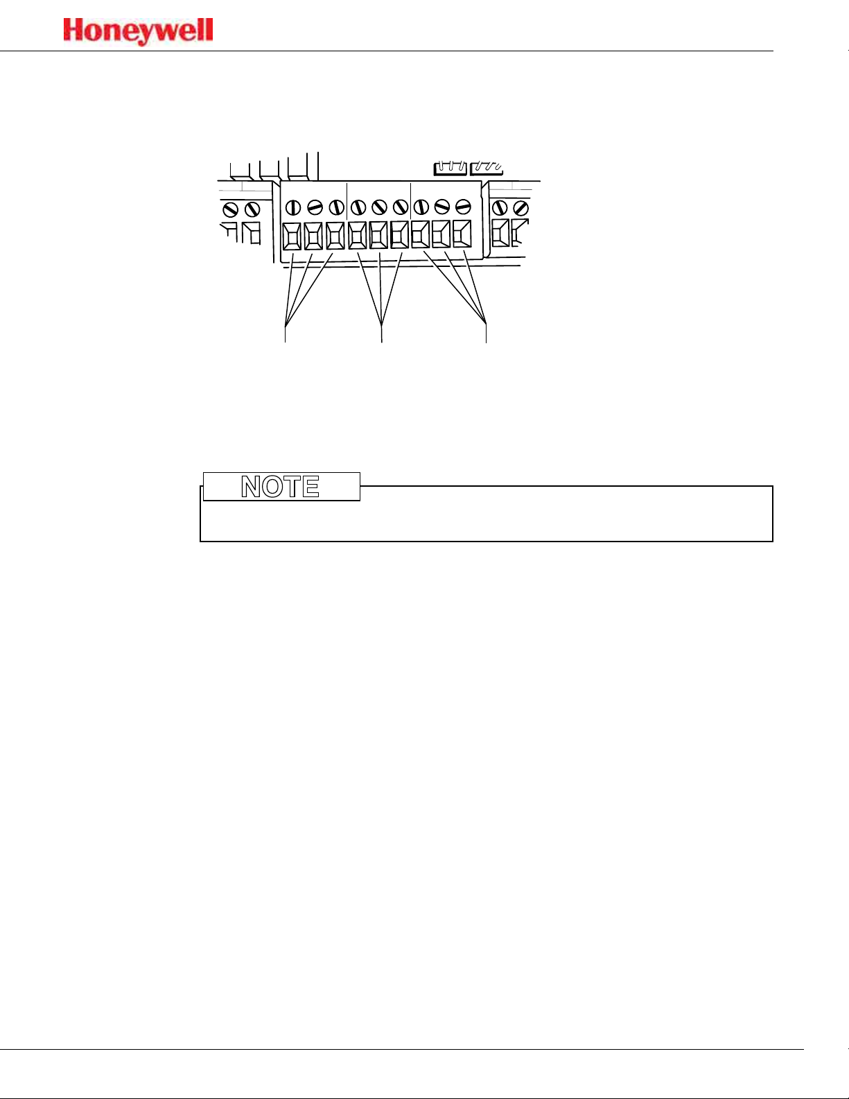
Relays
The detector is equipped with three relays� Connect the unit as shown in this
figure�
RELAY 1
+
4-20 mA
-
+
24 VDC
-
COM
FAULT
TERMINALS
Fault
NC
NO
Relay 2
NC
COM
RELAY 2
TERMINALS
Relay 1
NO
COM
NC
NO
TERMINALS
Figure 15. Relay conguration
The detector can be wired as normally closed or normally open� It can also be
configured as normally energized or normally de-energized via software�
NOTE
Do not wire relays and 4-20 mA in the same wire bundle�
By default, the relays are set to Alarm 1, Alarm 2, and Instrument Fault�
23
Page 24

SPM Flex Gas Detector
Modbus register definitions
Register Address/Name Bits Description Values
0: No Inhibit
1: Inhibit Alarm
0-2 Inhibit State
3 Instrument Fault 1 = Active
4 Maintenance Fault 1 = Active
5-6 Alarm State
40001 System Status
40002 Lastest Active Fault Code
40003-40004 Reported Concentration 32 bit Float
40005-40006 Actual Concentration 32 bit Float
40007-40011 Gas Abbreviation
40012 Concentration Display Format
40013-40014 Gas Table LDL 32 bit Float
40015-40016 LAL 32 bit Float
40017-40018 TLV 32 bit Float
40019-40020 Fullscale 32 bit Float
40021 Unused
40022 Alarm Enable
40023-40024 Alarm 1 Setpoint 32 bit Float
40025-40026 Alarm 2 Setpoint 32 bit Float
40027-40028 User LDL 32 bit Float
40029-40030 4-20 mA Fullscale 32 bit Float
40031 Chemcassette Code 16 bit Integer
40032 Chemcassette Days Remaining 16 bit Integer
40033 Flow 16 bit Integer
40034 Battery Level 16 bit Integer
40039 Heartbeat Counter
7 Monitor State
8 Conc Over Fullscale 1 = True
9-10 Concentration Trend
11 Alarm 1 Simulation 1 = Active
12 Alarm 2 Simulation 1 = Active
13 Instr. Fault Simulation 1 = Active
14 Maint. Fault Simulation 1 = Active
15 Unused
16 bit Integer
(0 = No fault)
9 byte string
including
terminator
0-1 Units 0: PPB
2-3 Decimal Places 0, 1 or 2
4-15 Unused
0 Alarm 1 Enabled 1 = Enabled
1 Alarm 2 Enabled 1 = Enabled
2-15 Unused
16 bit Integer
(increments
once per
second)
2: Inhibit Fault
3: Inhibit Alarm & Fault
4: Inhibit All
0: No Alarm
1: Alarm 1
2: Alarm 2
0: Not Monitoring
1: Monitoring
0: Stable
1:Rising
2: Falling
1: PPM
24
Page 25
SPM Flex Gas Detector
Tubing (optional)
Sample and exhaust tubing calculations
This table shows the flow rate, tubing length, transport time, and maximum
pressure and vacuum at the inlet and exhaust points�
Tubing lengths vary among gases� If the pressure or vacuum on the inlet/exhaust
lines does not meet the recommended values, the detector may encounter flow
faults�
Sample Specifications
Description Maximum
0
1
Inlet
Outlet
Tubing length, m (ft)
Transport time (sec)
Flow rate (cc/min.)
Tubing OD in mm (in.)
Tubing ID in mm (in.)
Tubing Length, m (ft) 30 (100)
Tubing OD, mm (in) 6.35 (0.25)
Tubing ID, mm (in) 4.76 (0.188)
30 (100) 20 (66)
19 13 7
700-1200 (flow is set and controlled per calibration)
6.35 (0.25)
3.18 (0.125)
10 (33)
The overall maximum load on the pump between the inlet and the exhaust should not exceed 10 inches H2O.
NOTE
Use Teflon Fluorinated Ethylene Polymer (FEP) tubing to ensure proper sample
transport�
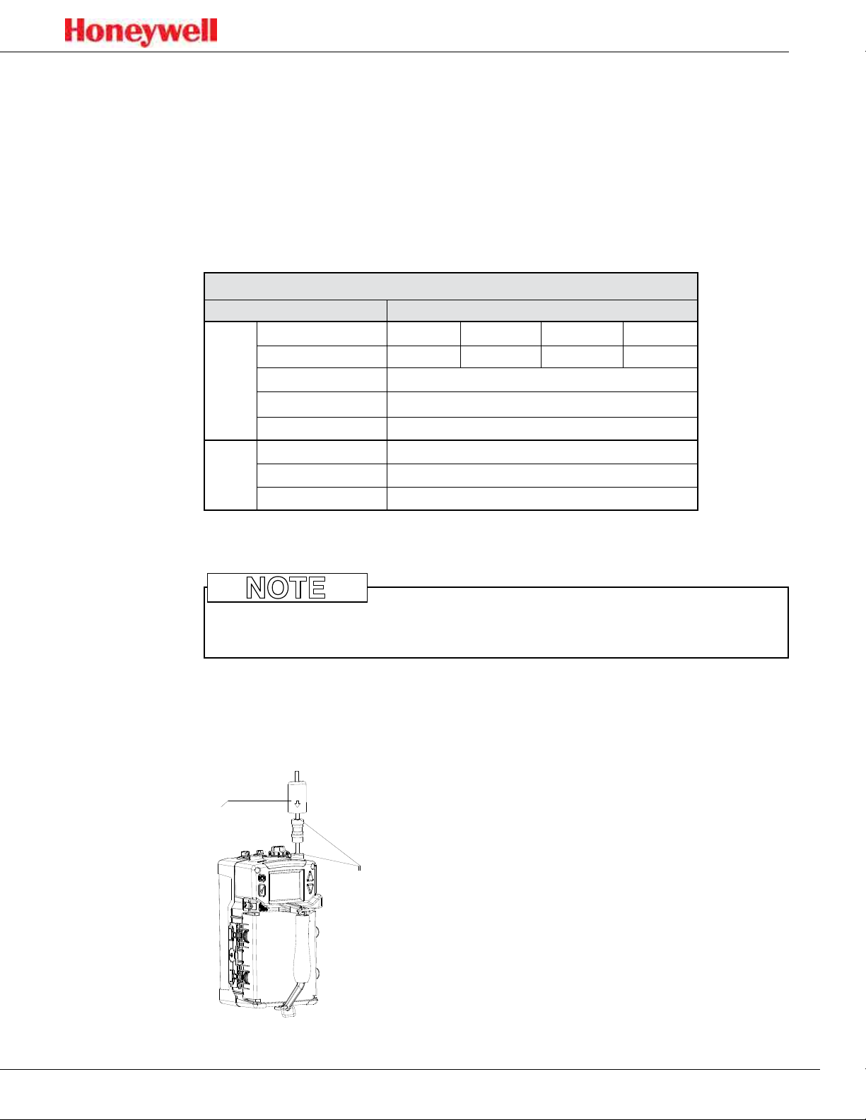
Optional external filters can be installed to reduce noise or to monitor for gas at
the location of the detector� To do this an inline filter is simply connected to the
gas inlet port� The area around the detector is then being monitored as opposed
to a sample being drawn from a remote location�
filter
John
Guest
fittings
Figure 16. External lter
25
Page 26
SPM Flex Gas Detector
Setup
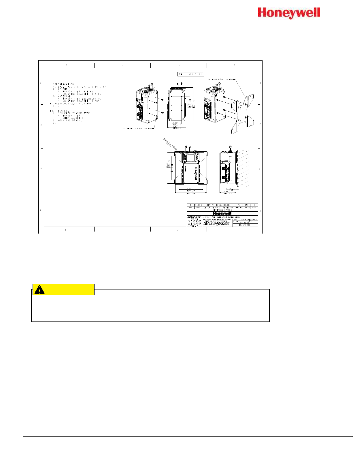
Installation drawing
Figure 17. Installation drawing
Mounting options
!
CAUTION
The SPM Flex detector must be installed only by qualified professional
personnel in accordance with local codes�
The SPM Flex gas detector has an optional mounting bracket assembly that is
easily affixed to a suitable vertical surface such as a wall, tool housing, mounting
plate on a pole etc�
Two mounting bracket options are available for fixed units: The standard kit is for
typical/new applications in which the detector is to be mounted to, for example, a
wall� A second option, a retrofit mounting, is a plate to be used when replacing a
Honeywell Analytics SPM detector with the SPM Flex detector�
Mount the detector with at least two appropriate fasteners (e�g�, concrete screws
when mounting on concrete, etc�)� The fastener combination must be capable of
securely holding four times the detector’s weight, approximately 40 lbs (18�2 kg)�
When mounting the detector on sheetrock, the fasteners must be attached to studs�
26
Page 27
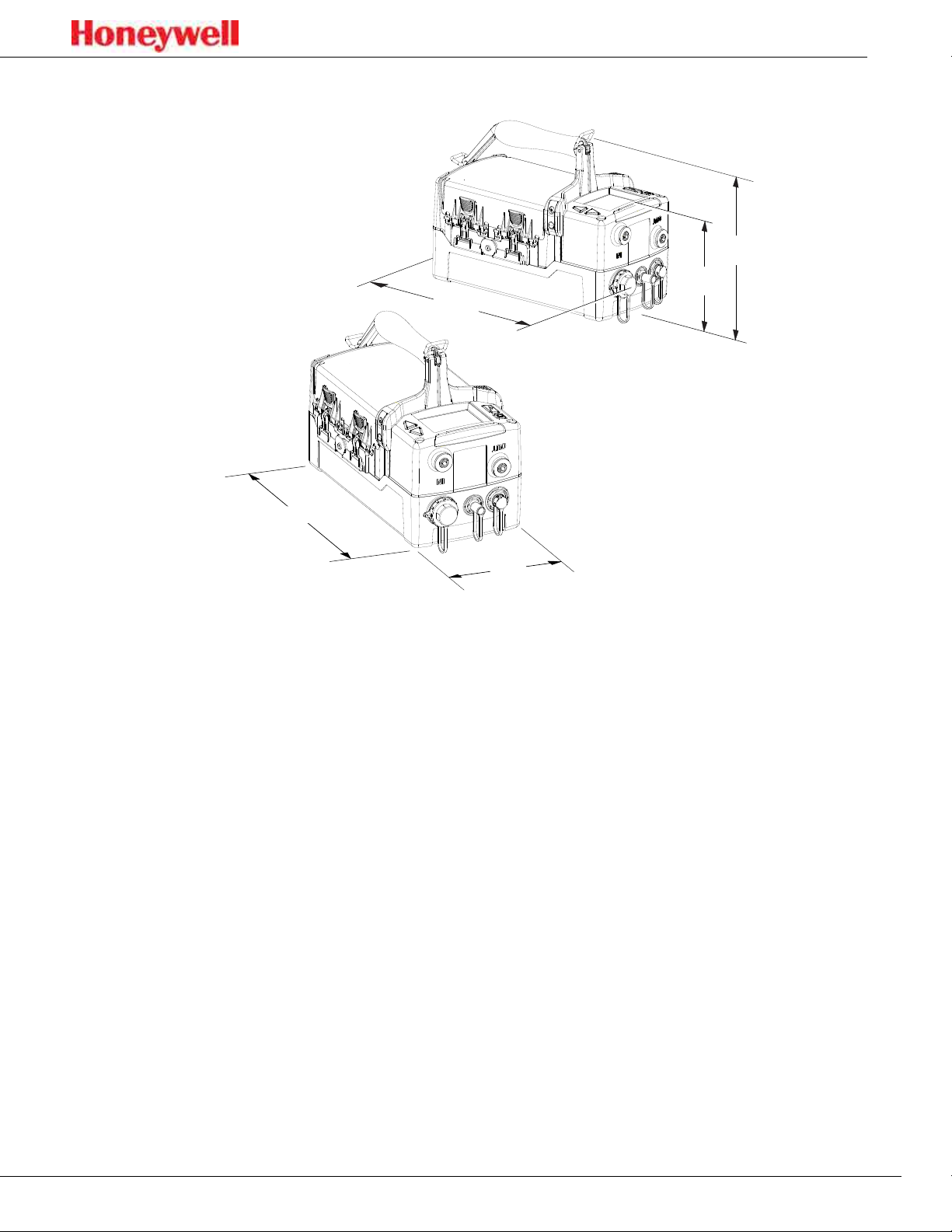
Dimensions
13.2 in.
(33.6 cm)
SPM Flex Gas Detector
9.5 in.
(24.1 cm)
6.4 in.
(16.3 cm)
12.3 in. (31.2 cm)
7.2 in.
(18.3 cm)
Figure 18. Dimensions of the SPM Flex Gas Detector
27
Page 28
SPM Flex Gas Detector
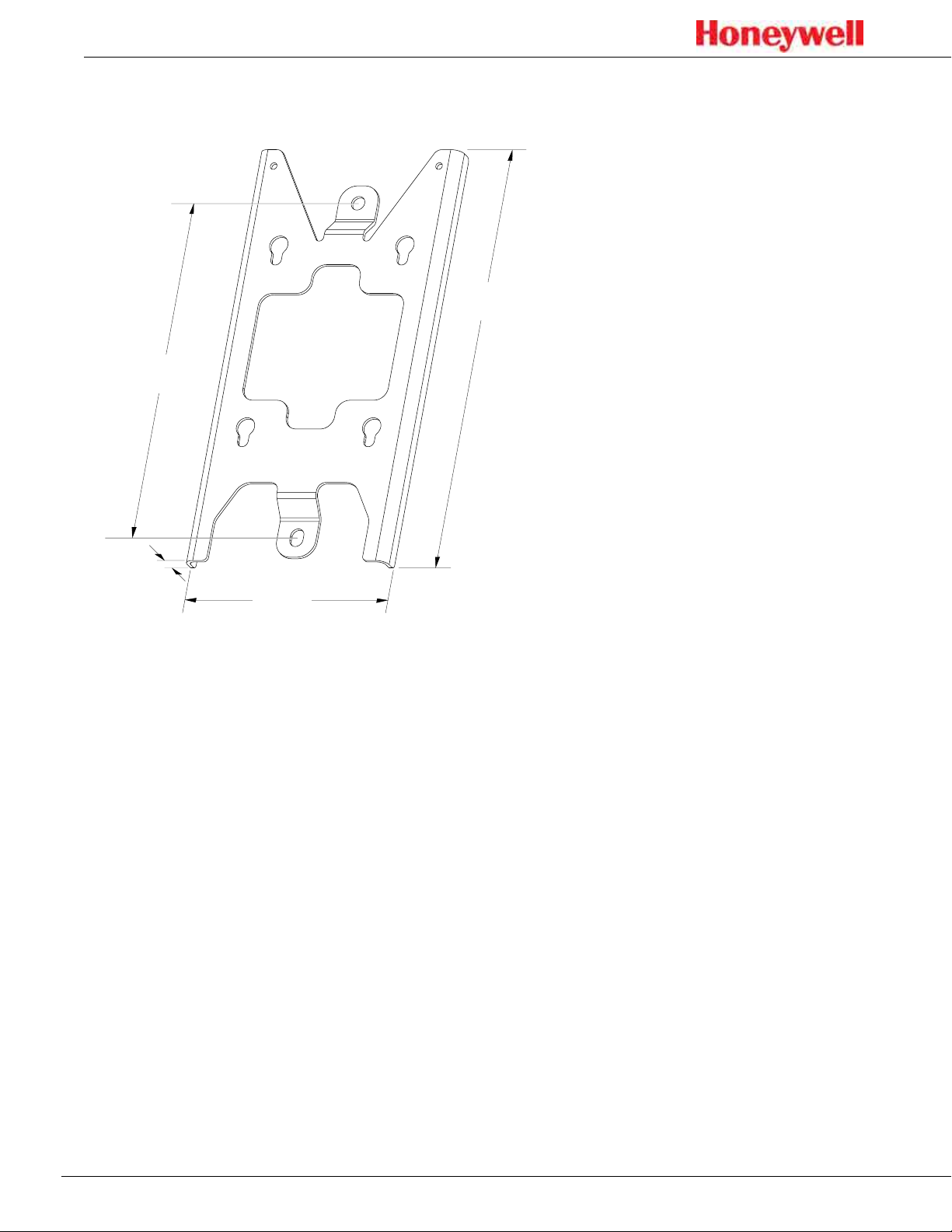
Standard mounting bracket
Figure 19 shows the detector’s standard mounting bracket�
12.5 in. (31.8 cm)
drilling holes:
10.2 in. (26.0 cm)
0.6 in. (1.6 cm)
6.3 in.
(15.9 cm)
Figure 19. Standard mounting bracket
At least 2 screws must be used when mounting the standard bracket to a wall�
Use the bracket as a template for determining the location of the holes to be
drilled in the wall� See the Specifications section on page 52 for a description of
the appropriate screws�
28
 Loading...