

Page 1
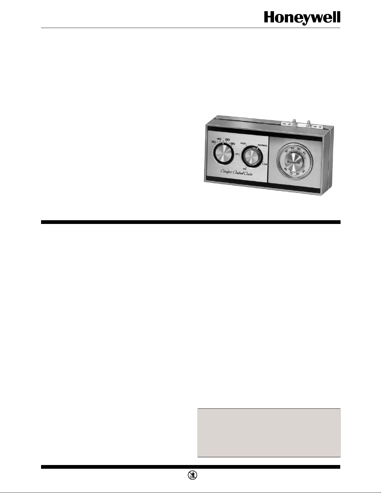
Comfort Control Center
The W884 Comfort Control Center provides
low voltage temperature and humidity control
in residential applications.
W884B,E
■ The W884B includes a humidifier control. The
W884E includes a dehumidifier control.
■ All comfort controls are combined in the W884
to make a convenient, attractive control center.
■ Humidistat dial on the W884B can be set for
prevailing outdoor temperature to provide optimum relative humidity over a wide range of conditions.
■ The dehumidistat on the W884E can be set to
CONTENTS
Specifications .................................................2
Ordering Information..................................... 2
Recycling Notice.............................................3
Installation .....................................................4
Settings and Adjustments................................7
Checkout.........................................................9
1 60-2289—6 J. H. • Rev. 3-93 • • ©Honeywell Inc. 1993 • Form Number 60-2289—6
M3375
Page 2

W884B,E
SPECIFICATIONS • ORDERING INFORMATION
positive ON and OFF for manual operation.
Specifications
IMPORTANT: The specifications given in this publi-
cation do not include normal manufacturing tolerances. Therefore, this unit may not match exactly
the listed specifications. Also, this product is tested
and calibrated under closely controlled conditions, and some minor differences in performance
can be expected if those conditions are changed.
MODELS:
W884B Comfort Control Center includes humidity
indicator, humidistat, switching subbase, and T87
Thermostat for controlling heating and cooling.
W884E Comfort Control Center includes humidity
indicator, dehumidistat, switching subbase, and
T87 Thermostat for controlling heating and cooling. May be used with heat pump or electric heat
applications.
DIMENSIONS: See Fig. 1.
VOLTAGE RATING: 30 Vac maximum (except indica-
tor lights, which are rated for 25 Vac).
ACCESSORIES AND REPLACEMENT PARTS:
Part No. 133262A Cover Plate Assembly for mount-
ing W884 on outlet box.
Part No. 104994A Calibration Wrench.
HUMIDISTAT RATINGS:
Switching:
W884B: Spst (makes on relative humidity de-
crease).
W884E: Spst (makes on relative humidity increase).
Switch Rating: 50 VA at 24 Vac.
Range:
W884B: Optimum relative humidity is maintained
by setting for outdoor temperature.
W884E: The dial is marked ON, LOW, NOR-
MAL, HIGH, and OFF. Optimum relative humidity is maintained by rotating the humidity
selection dial.
DIFFERENTIAL: 4 to 6 percent RH (cycling at midscale).
THERMOSTAT RATINGS:
Switching: Spdt.
Switch Rating: 1.5A at 30 Vac.
Range: 50° F to 100 ° F [10° C to 38° C].
Adjustable Heat Anticipator Range: 0.10 to 1.2A
(factory-set at 0.4A).
SUBBASE RATINGS:
System Switch: COOL-OFF-HEAT.
Fan Switch: AUTO-ON.
Switch Rating: 2A at 30 Vac; 1.5A at 30 Vdc.
Cooling Anticipator: 24 to 30 Vac.
Ordering Information
When purchasing replacement and moderniazation products from your TRADELINE® wholesaler or your distributor, refer to the
TRADELINE Catalog or price sheets for complete ordering number, or specify—
1.
Order number.2. Thermostat and subbase models if required.
3. Accessories (see list).
If you have additional questions, need further information, or would like to comment on our products or services, please write or
phone:
1. Your local Honeywell Home and Building Control Sales Office (check white pages of phone directory).
2. Home and Building Control Customer Satisfaction
Honeywell Inc., 1885 Douglas Drive NorthMinneapolis, Minnesota 55422-4386 (612) 951-1000
In Canada—Honeywell Limited/Honeywell Limitée, 740 Ellesmere Road, Scarborough, Ontario M1P 2V9. International
Sales and Service Offices in all principal cities of the world. Manufacturing in Australia, Canada, Finland, France, Germany,
Japan, Mexico, Netherlands, Spain, Taiwan, United Kingdom, U.S.A.
2
Page 3
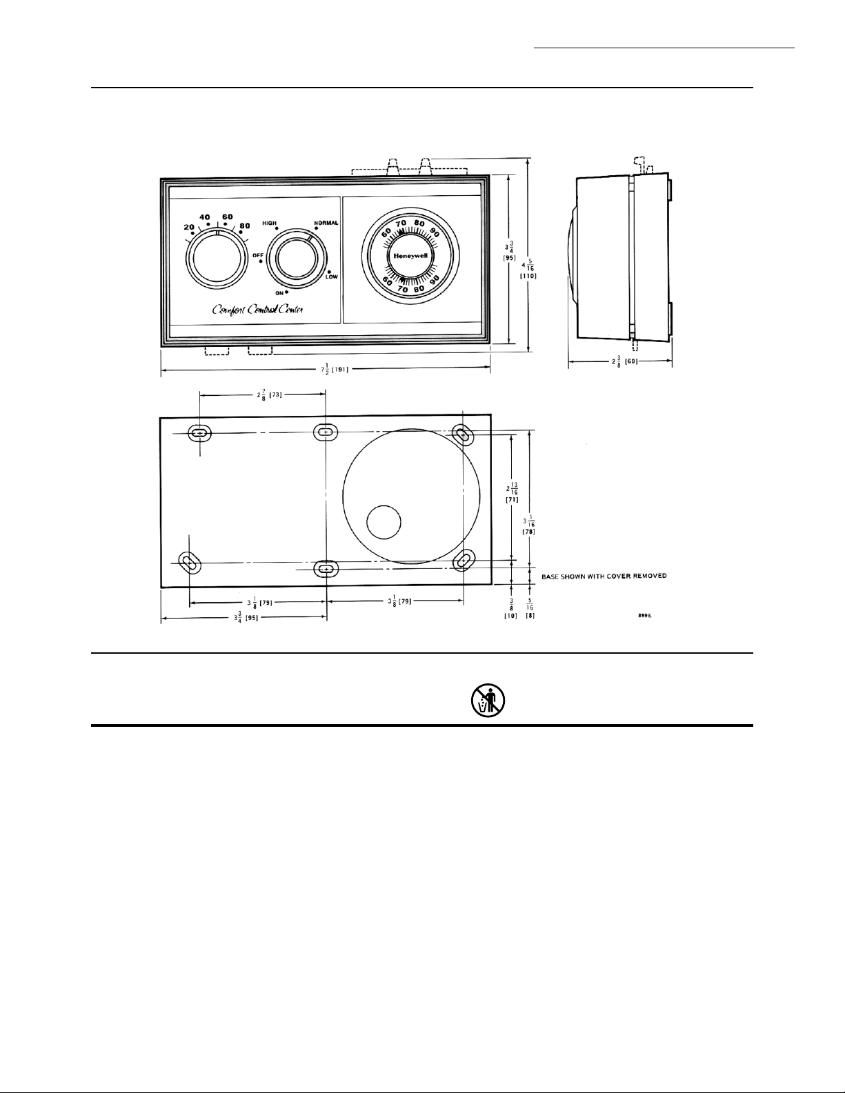
Fig. 1—W884 dimensions in in. [mm in brackets].
M3375
W884B,E
SPECIFICATIONS • RECYCLING NOTICE
Recycling Notice
This control contains mercury in a sealed tube. Do not
place control in the trash at the end of its useful life.
If this control is replacing a control that contains mercury in a sealed tube, do not place your old control in the
trash.
Contact your local waste management authority for
instructions regarding recycling and the proper disposal
of this control, or of an old control containing mercury in
a sealed tube.
If you have questions, call Honeywell at 1-800-468-
1502.
3 60-2289—6
Page 4
W884B,E
INSTALLATION
WHEN INSTALLING THIS PRODUCT…
1. Read these instructions carefully. Failure to follow them could damage the product or cause a hazardous condition.
2. Check the ratings given in the instructions and on
the product to make sure the product is suitable for your
application.
3. Installer must be a trained, experienced service
technician.
4. After installation is complete, check out product
operation as provided in these instructions.
!
Installation
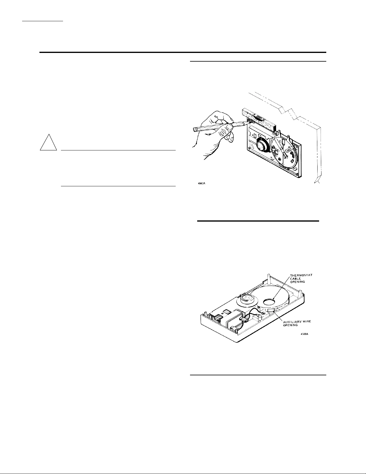
Fig. 2—Level the W884 and then mark the
position of mounting holes with a pencil.
CAUTION
1. Disconnect power supply before beginning
installation to prevent electrical shock or
equipment damage.
2. On gas systems, turn off gas before starting
installation.
LOCATION
Locate the W884 about 5 ft [1.5 m] above the floor in
an area with good air circulation at average temperature.
Do not mount the W884 where it may be affected by:
—drafts, or dead spots behind doors and in corners.
—hot or cold air from ducts.
—radiant heat from the sun or appliances.
—concealed pipes and chimneys.
—unheated (uncooled) areas such as an outside wall
behind the thermostat.
MOUNTING
IMPORTANT: The thermostat used with the W884 was
mounted at true level when calibrated at the factory. The W884 must be level to maintain calibration.
1. Remove cover and thermostat and level W884 at
the selected location. Mark locations for mounting screws
and wiring access hole. See Fig. 2.
2. Drill a 1/2 to 3/4 in. [13 to 19 mm] hole for the
wires, and small pilot holes for the mounting screws.
3. Run cable and auxiliary wires (if used) to location.
Pull in the required number of wires. All wiring is 24V.
4. Carefully slip the thermostat wires through the
hole in the subbase, and insert humidistat and auxiliary
wires (if used) through the square wiring hole on the side
of the subbase platform. See Figs. 3 and 4.
Fig. 3—Thermostat wires are brought through
the hole on the subbase; wires for the humidistat are brought through the hole on the side
of the subbase platform.
4
Page 5
INSTALLATION
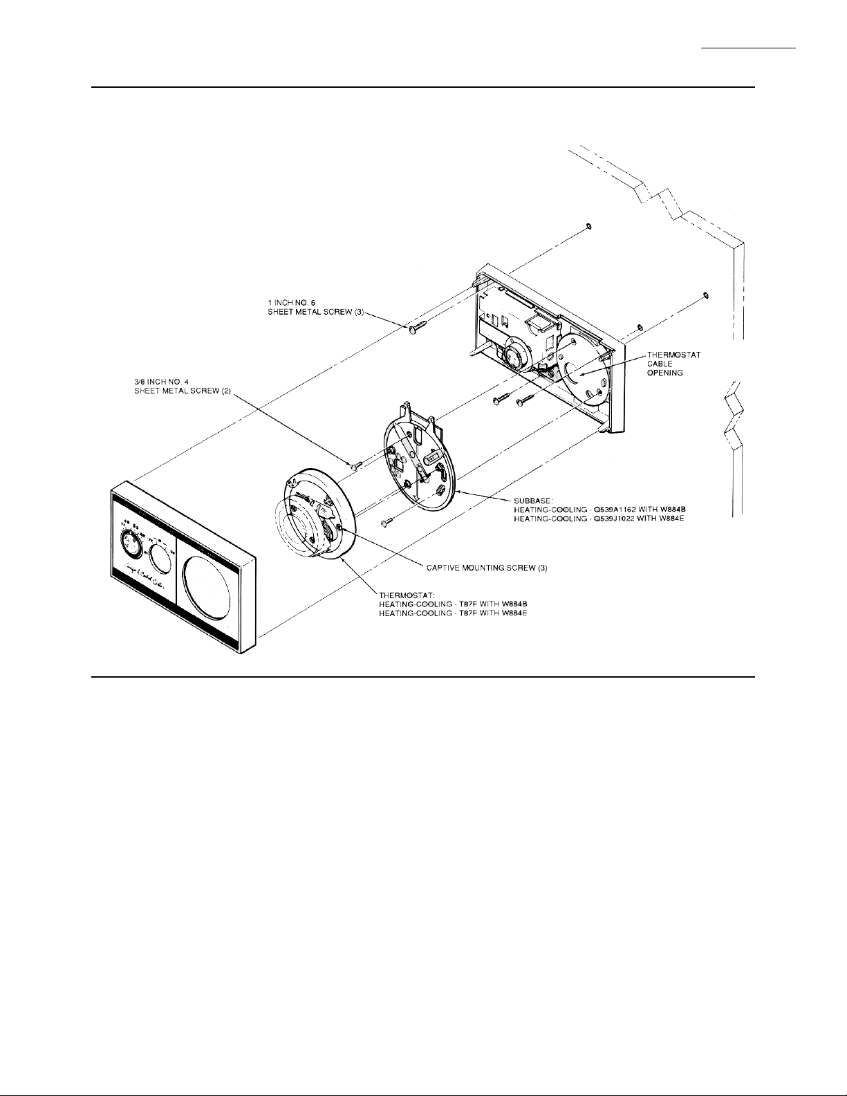
Fig. 4—The W884 comfort control center has interchangeable thermostats and subbases to provide for
several types of operation.
W884B,E
5. Use the three 1-in. screws to mount the W884 on
the wall. Before tightening the screws, level as accurately as possible using a spirit level placed on top of the
W884. Tighten the screws. For mounting on a junction
box, use part no. 133262A Backplate Assembly (order
separately).
6. Connect the color-coded wires to the subbase and
humidistat (see Wiring section). Push excess wire back
into wall, and plug the hole to prevent drafts from affecting the W884.
7. Mount the thermostat, and replace W884 cover.
WIRING
Disconnect power supply to prevent electrical shock
or equipment damage.
All wiring must comply with local codes and ordi-
nances.
Wiring to the W884 must be NEC Class 2.
Humidistat requires separate 24V power supply.
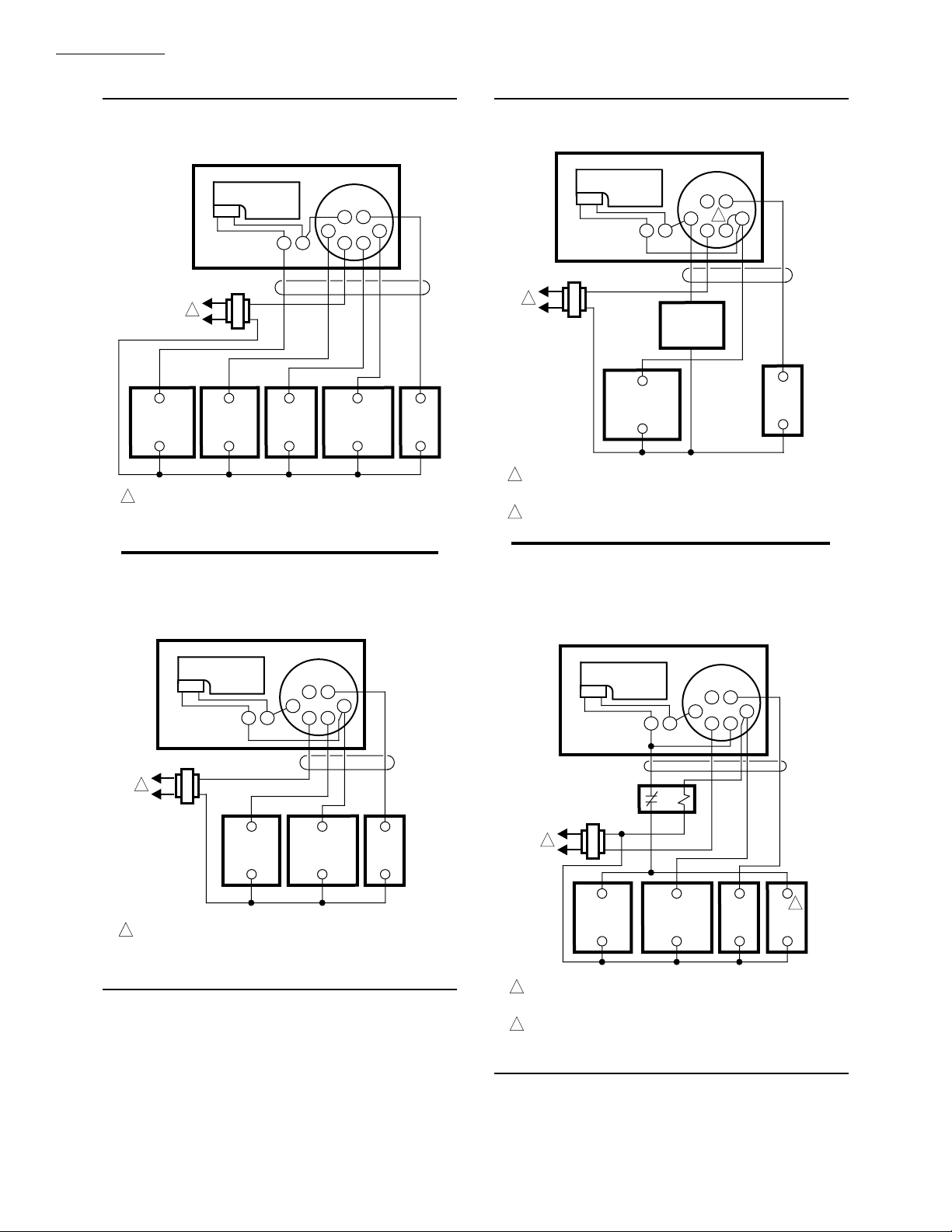
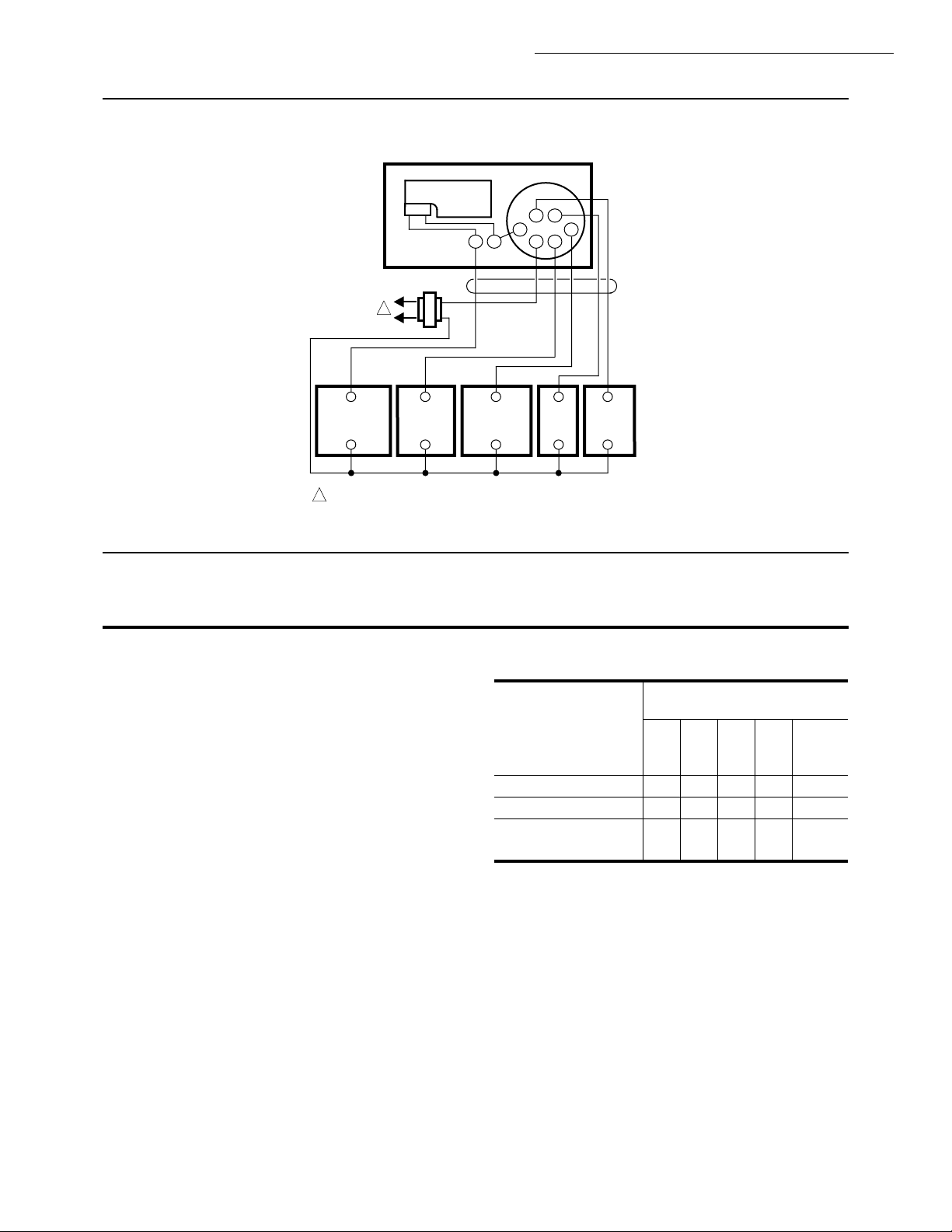
Refer to the wiring diagrams and instructions packed
with the thermostat and subbase, and Figs. 5-9.
5 60-2289—6
Page 6
W884B,E
INSTALLATION
Fig. 5—W884B heating-cooling application. Fig. 7—W884E in heat pump application.
W884B
HUMIDISTAT
H
1
HUMIDIFIER
RELAY
1
POWER SUPPLY. PROVIDE DISCONNECT MEANS AND OVERLOAD
PROTECTION AS REQUIRED.
COOLING
DAMPER
MOTOR
HEATING
RELAY
H
Q539A
G
B
O
R
W
COOLING
CONTACTOR
Y
FAN
RELAY
M1332
Fig. 6—W884E in system with separate heating
and cooling. Dehumidistat energizes on
cooling.
W884E
DEHUMIDISTAT
H
1
HEAT PUMP
COMPRESSOR
RELAY
POWER SUPPLY. PROVIDE DISCONNECT MEANS AND OVERLOAD
1
PROTECTION AS REQUIRED.
ADD JUMPER BETWEEN W AND Y TERMINALS.
2
Q539J
H
REVERSING
VALVE
B G
2
R
YO
W
FAN
RELAY
Fig. 8—W884E with separate heating and
cooling. Dehumidistat energizes heating.
Switching relay deenergizes heating when
cooling is initiated.
M1334
W884E
DEHUMIDISTAT
H H
1
HEATING
RELAY OR
VALVE
POWER SUPPLY. PROVIDE DISCONNECT MEANS AND OVERLOAD
1
PROTECTION AS REQUIRED.
Q539J
G
B
O
R
W
COOLING
CONTACTOR
Y
FAN
RELAY
M1333
W884E
DEHUMIDISTAT
H
SPST N.C.
SWITCHING
RELAY
1
HEATING
RELAY OR
VALVE
POWER SUPPLY. PROVIDE DISCONNECT MEANS AND OVERLOAD
1
PROTECTION AS REQUIRED.
USED IN DUCT HEATER OR SIMILAR APPLICATIONS TO ENERGIZE
2
SYSTEM FAN DURING HEATING.
COOLING
CONTACTOR
Q539
B G
O
H
R
W
FAN
RELAY
Y
FAN
RELAY
2
M1335
6
Page 7
INSTALLATION • SETTINGS AND ADJUSTMENTS
Fig. 9—W884E with separate heating and cooling, dehumidifier relay coil, heating damper motor.
W884E
DEHUMIDISTAT
H
1
Q539
B
G
O
H
Y
R
W
W884B,E
DEHUMIDIFIER
RELAY
1
POWER SUPPLY. PROVIDE DISCONNECT MEANS AND OVERLOAD
PROTECTION AS REQUIRED.
HEATING
RELAY OR
VALVE
TEMPERATURE SELECTION
To select the temperature control point, turn the transparent dial until the pointer is in line with the desired
point on the setting (top) scale.
HUMIDITY SELECTION
IMPORTANT: If the humidistat is set too high during
cold weather, condensation on windows may occur.
This indicates there is too much moisture in the air,
which could lead to structural damage if allowed to
persist. Set the humidistat at the recommended
setting shown below. If humidistat is set as recommended and frost or condensation forms on inside
windows, adjust humidistat setting for outdoor temper-ature setting less 5°F [3°C]. Frost or condensation should disappear within 24 hours. If not, continue reducing outdoor temperature setting and adjust humidistat accordingly.
Humidity Selection W884B
The humidity controller should be set at the prevailing outdoor temperature. This will provide optimum
relative humidity control for most installations.
COOLING
CONTACTOR
FAN
RELAY
HEATING
DAMPER
MOTOR
M1331
Settings and Adjustments
TABLE 1—
RECOMMENDED RELATIVE HUMIDITY LEVEL.
Outdoor Temperature
(Degrees F)
+20
Type Of and
Construction -20 -10 0 +10 Above
Double Glass 15% 20% 25% 30% 35%
Single Glass 10% 15% 20% 25% 30%
Single Glass 20% 25% 30% 35% 40%
with Storm Window
Humidity Selection W884E
The humidity selection dial can be set to any position
between ON and OFF. The HIGH position is approximately 70 percent relative humidity; normal is approximately 50 percent RH, and LOW is approximately
30 percent RH.
NOTE: For dehumidification in cooling, the W884E
should be wired in parallel for independent control of
temperature and relative humidity.
7 60-2289—6
Page 8
W884B,E
SETTINGS AND ADJUSTMENTS
The recommended maximum settings for mildew pre-
vention are 60 percent RH and 85° F [29 ° C].
HUMIDITY ADJUSTMENT (All Models)
In some cases, it may be desirable to deviate from
recommended setting. The setting knob has a movable
pointer, which can be adjusted to produce an upward or
downward shift in the setpoint of as much as six percent
relative humidity. Adjust as follows:
1. Remove the cover of the W884.
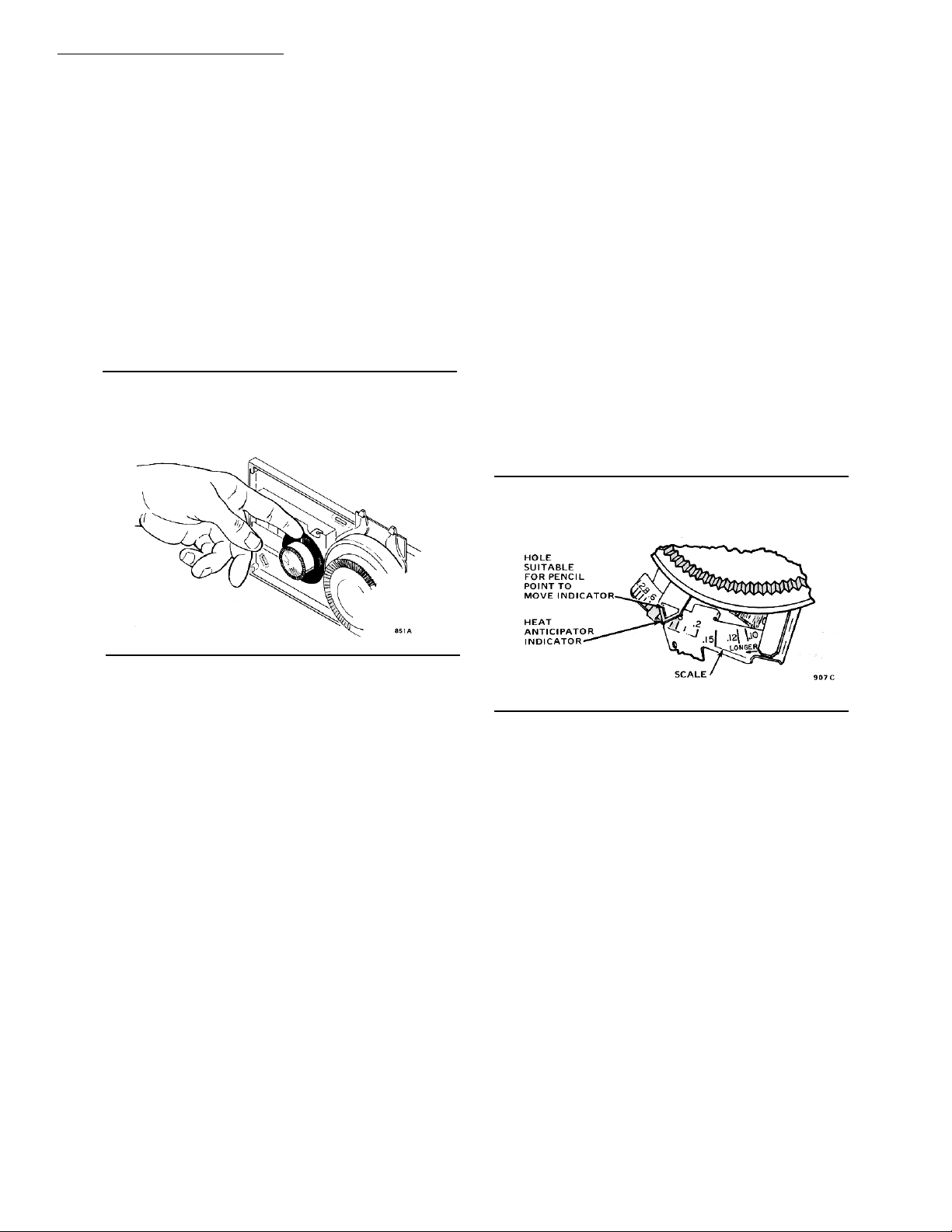
2. While holding the knob still, push the movable
pointer on the humidity setting dial toward MORE or
LESS. See Fig. 10.
For W884B only, set the pointer according to the type
of building construction (Table 1).
Fig. 10—An adjustment of ± six percent RH in
the humidity control point is possible by
moving the pointer of the knob.
THERMOSTAT HEAT ANTICIPATOR
ADJUSTMENT
Adjust the heat anticipator to match the current rating
of the primary control; this rating is usually stamped on
the control nameplate. Move the indicator on the scale to
correspond with this rating and the heat anticipator will
be properly adjusted. Move the indicator with your fingers, a pin, a pencil point, or a wire inserted in the small
hole. See Fig. 11. If the current rating is not given,
proceed as follows before mounting the thermostat:
1. Connect an ac ammeter of appropriate range (0 to
2.0A, for example) between the terminals R and W on
the subbase. The subbase system switch must be in the
HEAT position.
2. Let the heating system operate for one minute
before reading the ammeter.
3. Use this current reading to set the heat anticipator.
A slightly higher setting will produce longer burner-
on times (and thus fewer cycles per hour). This may be
desirable on some systems such as a one-pipe steam
system.
Fig. 11—T87F Heat Anticipator is adjusted to
HUMIDITY INDICATOR RECALIBRATION
(All Models)
The humidity indicator in the W884 Comfort Control
Center has been carefully calibrated at the factory and
should require no further adjustment.
If, after several hours of operation, it appears that
recalibration is necessary, proceed as follows:
1. Obtain a proven test hygrometer (humidity gauge).
Do not attempt to use the humidity from the weather
report or an ordinary hygrometer. This will result in an
inaccurate setting.
2. Place it near the humidity indicator and allow
several hours for its reading to stabilize.
3. Rotate the bracket holding the spiral sensing element in the W884 until the humidity indicator agrees
with the test hygrometer.
match the current draw of the primary control.
EXAMPLE: If burner-on time is too short with a set-
ting of 0.4, adjust it to 0.45 and check system operation. Make further adjustments as necessary until the
desired burner-on time is obtained.
THERMOSTAT CALIBRATION
The thermostat was accurately calibrated at the factory and should not need recalibration. If the thermostat seems out of adjustment, first check for accurate
leveling. Also check the location to be sure the thermostat is exposed to average room temperature only. Heat
due to nearby appliances, hot water pipes, fireplaces,
solar heat, radiators, and registers or cold due to drafts
or cold water pipes may affect operation.
If the thermostat is still out of calibration, order Part
No. 104994A Calibration Wrench. Instructions for
recalibration are furnished with the wrench.
8
Page 9
When installation and adjustments are complete, observe system through one complete cycle to make sure
all components function as intended.
CAUTION
!
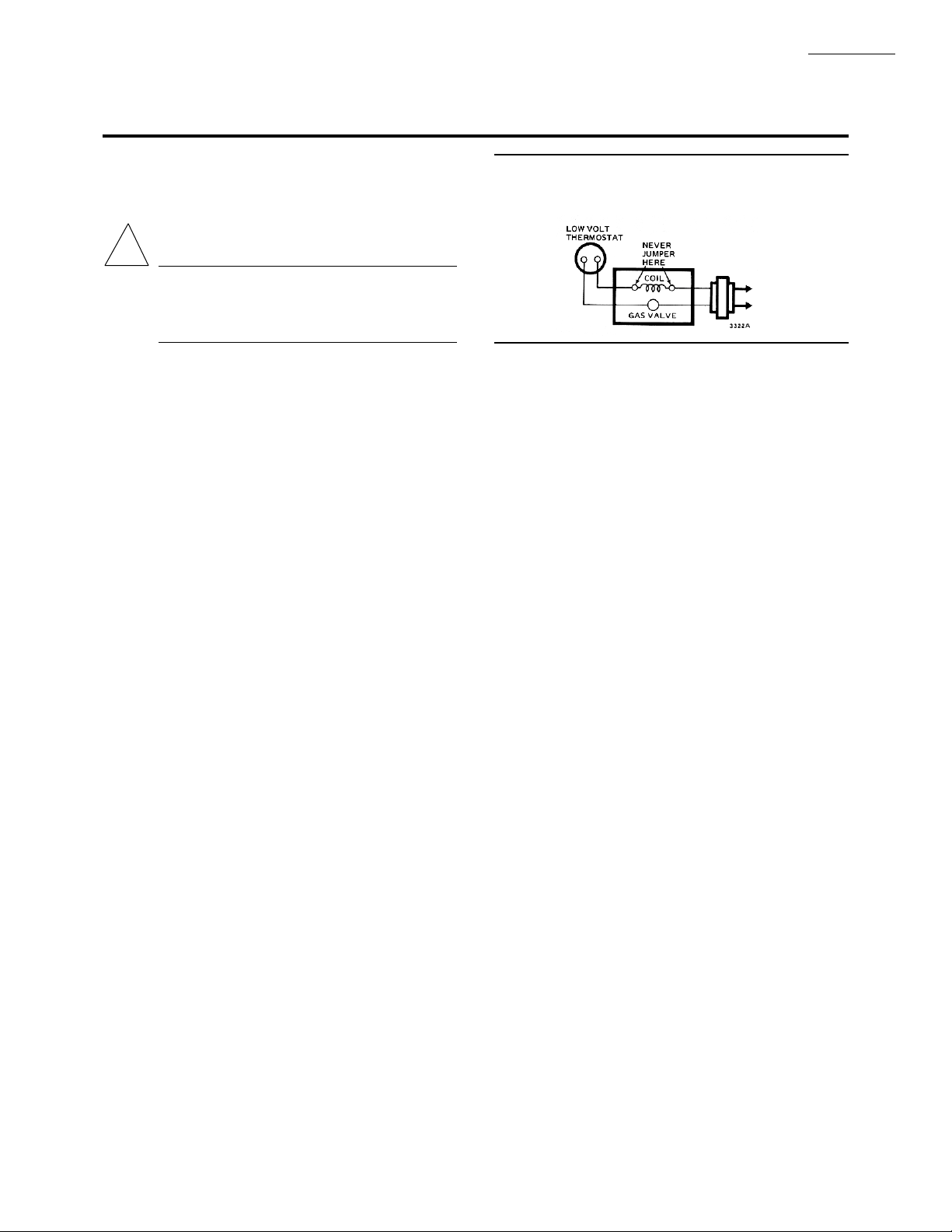
On low voltage gas system, if jumpering gas
valve to check system operation, do NOT
jumper across valve coil. This may burn out
thermostat heat anticipator. See Fig. 12.
W884B,E
CHECKOUT
Checkout
Fig. 12—Do not jumper across valve coil.
9 60-2289—6
Page 10

Home and Building Control Home and Building Control Helping You Control Your World
Honeywell Inc. Honeywell Limited—Honeywell Limitée
1985 Douglas Drive North 740 Ellesmere Road
Golden Valley, MN 55422 Scarborough, Ontario
M1P 2V9
Printed in U.S.A.
QUALITY IS
KEY
10
 Loading...