

Page 1
69-2481EF-01
TrueFRESH™ Ventilation System
OWNER’S GUIDE
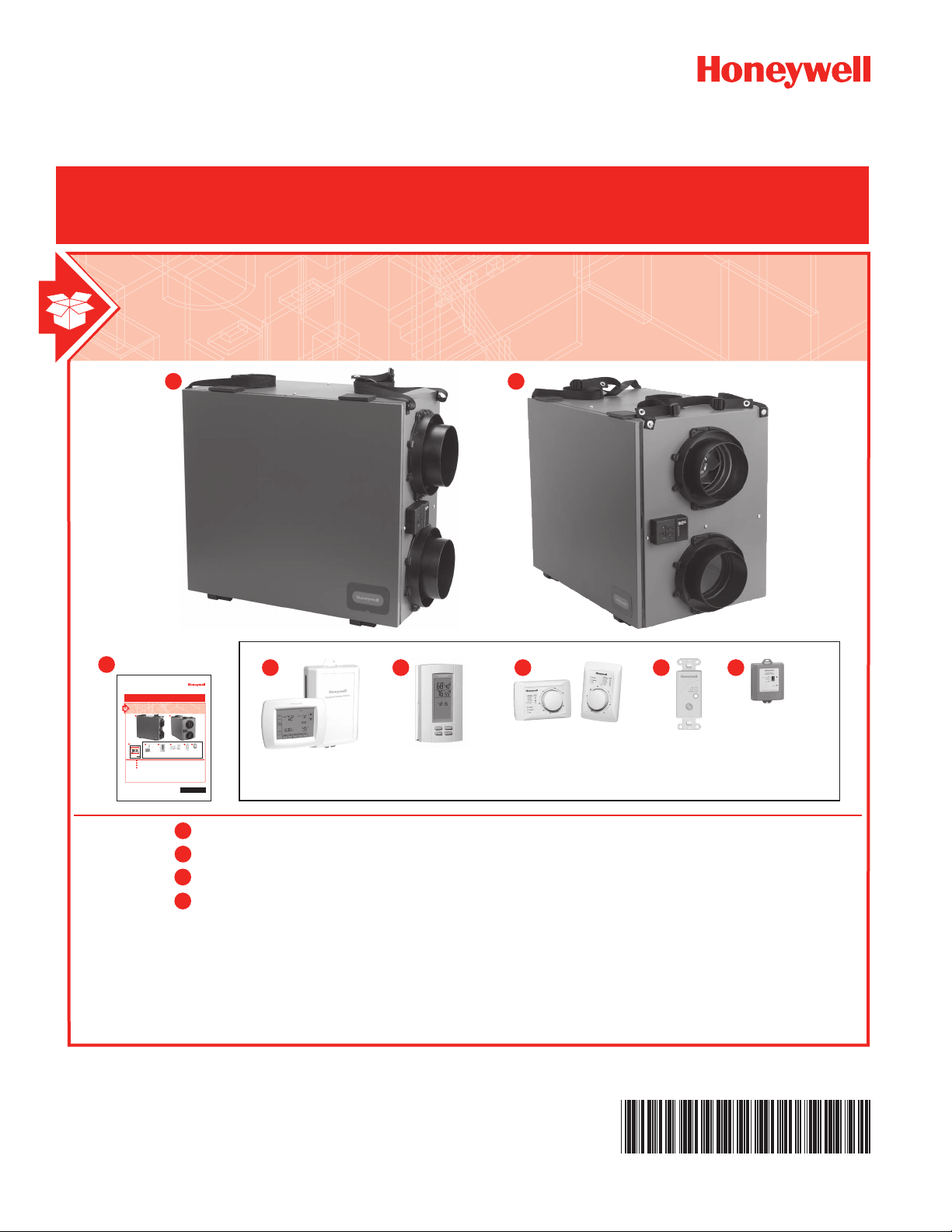
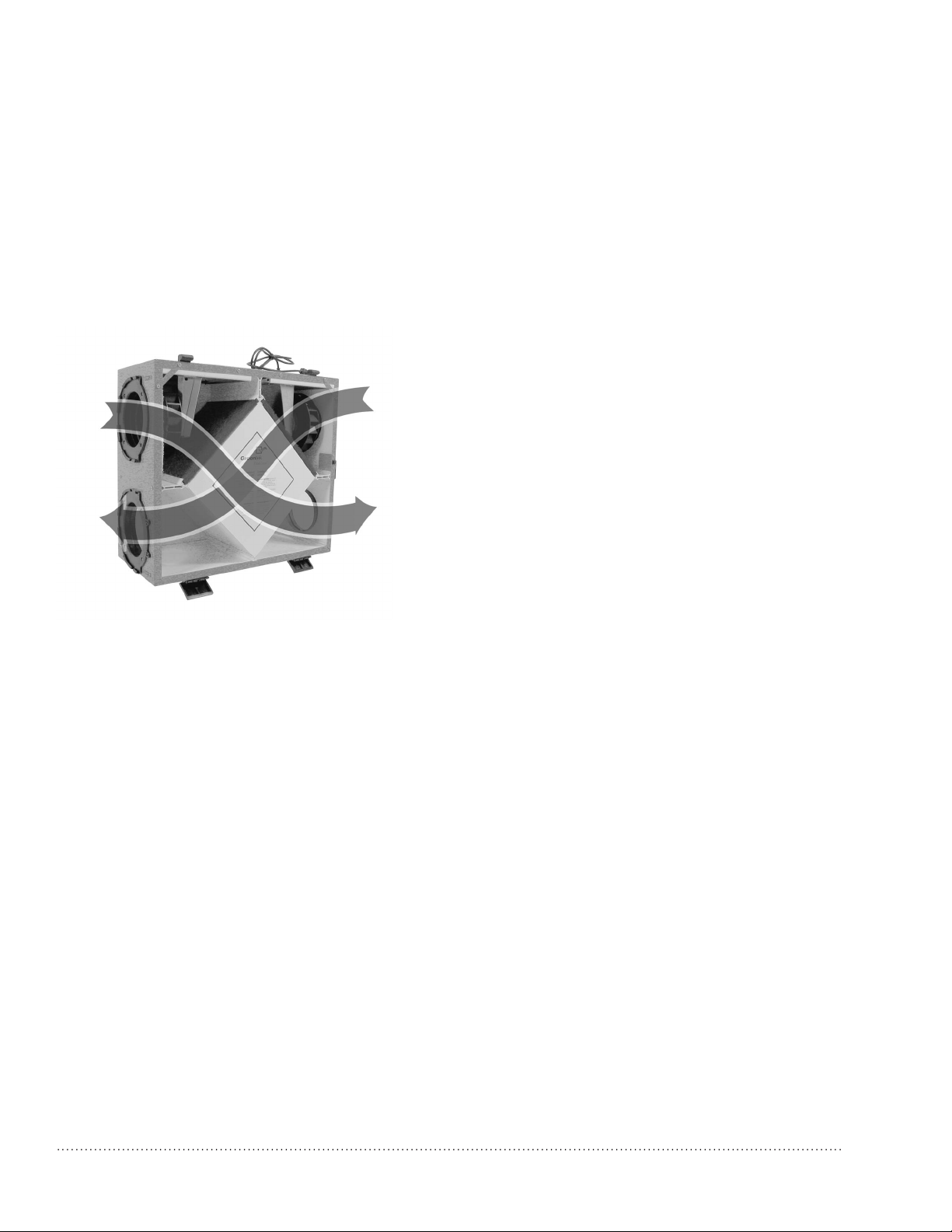
INCLUDED IN THIS BOX
B
TrueFRESH™ Ventilation System
INCLUDED IN THIS BOX
A1
B
TrueFRESH™ Ventilation System
INCLUDED IN THIS BOX
A1A1A2
B
C1 C2 C3 C4C5
TrueFRESH™ Ventilation System
OWNER’S GUIDE
INCLUDED IN THIS BOX
AAA
B
CCCCC
OPTIONAL CONTROLS SOLD SEPARATELY
TrueFRESH™ VNT5150H1000 or VNT5150E1000
TrueFRESH™ VNT5200H1000 or VNT5200E1000
A
Owner’s Guide
B
C
Optional Controls:
1. Vision Pro IAQ
OPTIONAL CONTROLS SOLD SEPARATELY
2. True IAQ
3. Dehumidistat H8908
4. 20/40/60 Minute Boost Control
5. W8150 Ventilation Control
69-2481EF-01
TrueFRESH™ VNT5150H1000 or VNT5150E1000
TrueFRESH™ VNT5200H1000 or VNT5200E1000
A2
Owner’s Guide
B
Optional Controls:
C
1. Vision Pro IAQ
2. True IAQ
3. Dehumidistat H8908
4. 20/40/60 Minute Boost Control
5. W8150 Ventilation Control
A1
A2
C1 C2 C3 C4 C5
OWNER’S GUIDE
OPTIONAL CONTROLS SOLD SEPARATELY
69-2481EF-01
TrueFRESH™ VNT5150H1000 or VNT5150E1000
TrueFRESH™ VNT5200H1000 or VNT5200E1000
Owner’s Guide
B
Optional Controls:
C
1. Vision Pro IAQ
2. True IAQ
3. Dehumidistat H8908
4. 20/40/60 Minute Boost Control
5. W8150 Ventilation Control
A1
C1 C2 C3 C4 C5
OWNER’S GUIDE
A2
OPTIONAL CONTROLS SOLD SEPARATELY
69-2481EF-01
TrueFRESH™ VNT5150H1000 or VNT5150E1000
A1
TrueFRESH™ VNT5200H1000 or VNT5200E1000
A2
Owner’s Guide
B
Optional Controls:
C
1. Vision Pro IAQ
2. True IAQ
3. Dehumidistat H8908
4. 20/40/60 Minute Boost Control
5. W8150 Ventilation Control
A2
Page 2

Installation Checklist
Included in This Box
A1 TrueFRESH™ VNT5150H1000 or VNT5150E1000
A2 TrueFRESH™ VNT5200H1000 or VNT5200E1000
B Owner’s Guide
Control Options (Sold separately)
C1 Prestige™ and Prestige™ IAQ Comfort System
(wireless)
C2 TruelAQ
C3 H8908 Manual Dehumidistat
C4 VisionPRO and VisionPRO IAQ control
C5 W8150 Ventilation Control
Warning: Installation must be performed by a
qualied service technician and must comply with
local codes.
Remove power to the device before installing or
servicing the device.
Failure to connect the device according to these
instructions may result in damage to the device or
the controls.
INSTALLATION INSTRUCTIONS
BEGIN ON PAGE 1
Page 3

TrueFRESH™ Ventilation System
OPERATION
Operation and Main Function .................................... 2
Description .................................................................5
Control Panel .............................................................. 6
Balncing Steps ...........................................................7
Operating Your wall Controls ..................................... 8
TROUBLESHOOTING
Troubleshooting .......................................................... 9
MAINTENANCE
Periodic Maintenance ..............................................10
Cleaning .................................................................... 11
WARRANTY
5-Year Limited Warranty ...........................................12
• The product is for residential applications only and must be installed in accordance
with all national and local regulations, building and safety codes
NEED HELP? For assistance with this product please visit http://yourhome.honeywell.com
or call Honeywell Customer Care toll-free at 1-800-468-1502.
?
Read and save these instructions.
® U.S. Registered Trademark. Patents pending. Copyright © 2011 Honeywell International Inc. All rights reserved.
TrueFRESH™ Ventilation System 69-2481EF—01
1
Page 4
Operation and Main Function
Your ventilation system has been engineered & designed to improve your indoor air quality by reducing
during the winter time, excess humidity or other contaminants in your home and replacing this air by fresh
filtered air from the outdoors. During colder seasons, the units heat recovery core (polypropylene core)
will reclaim the heat from the outgoing stale air and use this heat to temper the incoming fresh air, which
reduces the cost of effectively ventilating your home during winter.
NOTE: Reverse process occurs in the summer months.
System Installation (examples)
A
Bathroom
Control floor
Ground floor
Fresh air supply hood
Exhaust air hood
Basement
Independent System
HRV/ERV
2
TrueFRESH™ Ventilation System 69-2481EF—01
Page 5
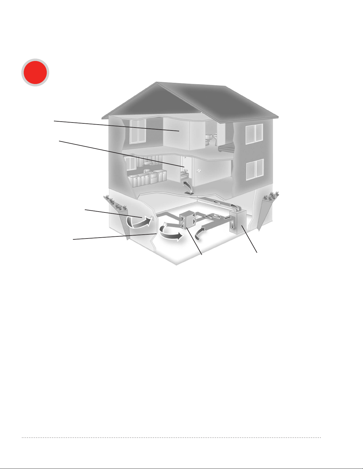
Operation and Main Function
B
Bathroom
Control floor
Ground floor
Fresh air supply hood
Exhaust air hood
Basement
Exhaust at the Source and Supply in the Return
HRV/ERV
Forced Air
System
TrueFRESH™ Ventilation System 69-2481EF—01 3
Page 6
Operation and Main Function
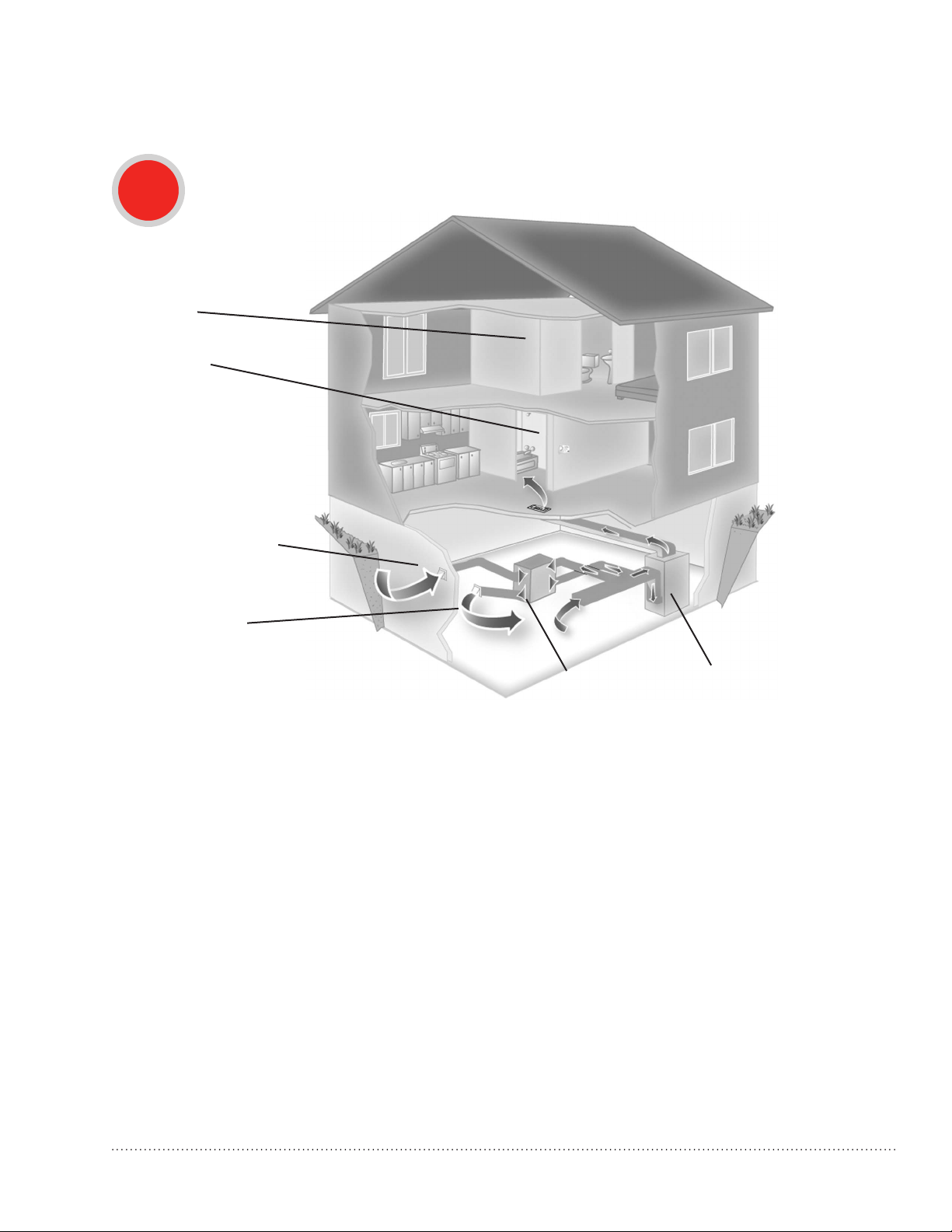
C
Bathroom
Control floor
Ground floor
Fresh air supply hood
Exhaust air hood
Basement
Exhaust and Supply in the Return
HRV/ERV
Forced Air
System
4
TrueFRESH™ Ventilation System 69-2481EF—01
Page 7
Description
Ventilation System with Recirculation
Mode
A. Fresh air from outside
B. Exhaust air to outside
C. Exhaust air from home
D. Fresh air to home
C
A
B
• Fresh Air from Outside Port (A): Inlet for fresh
outdoor air.
• Exhaust Air to Outside Port (B): Outlet for
exhausting stale, humid and contaminated air
to the outdoors after transferring its heat to the
recovery core.
• Exhaust Air From Home Port (C): Exhausts stale,
humid and contaminated air to the outside from
multiple location of the home or from the return
air of the forced air system, prior to passing
threw the heat recovery core. Ex: Bathroom,
laundry room, etc.
• Fresh Air to Home Port (D): Introduces &
distributes clean & fresh air to your home. The
homes fresh air ports are normally installed in
the main living areas or in the return/supply
duct of the forced air system. Ex: Living room,
bedrooms, recreation rooms, etc.
• Control Panel: Selects your ventilation modes
(OFF, CONT or INTER), also to adjust your
continuous airflow rates: Increasing (+)/
Decreasing (-).
• Synthetic Filters: Capture the largest particle and
protects your heat recovery core from potential
obstruction by these particles.
D
• Heat Recovery Core: A polypropylene cross-flow
type it is designed to transfer the heat between
both exhaust & supply air streams without
allowing any contamination or mixing of both air
streams to maximize the efficient and improve
your indoor air quality.
• Condensate Drain Pan & Drainage Hose:
Captures the water that accumulates during
the heat transfer and defrosts sequence in
the fall, winter & early spring seasons. Drain
hose is connected to the drain pan and serves
as drainage for the accumulation of water. It
is normal during summer months to find no
condensation in drain pan or in drainage hose.
• Automatic Defrost Sequence: The ERV and HRV
units are equipped with an automatic defrost
feature to eliminate any ice build up on the core.
Automatic defrost is initiated once every hour
when the fresh air supply temperature drops to
23°F (-5°C) or colder.
- The defrost cycle operates by turning off the
supply fan while continuing to operate the
exhaust fan.
- The exhaust fan speed is adjusted
proportionally based on the outdoor
temperature, initially operating at low speed.
- As the outdoor temperature continues to
drop, the exhaust fan speed will increase,
and will operate at maximum speed when
the outdoor temperature is -4°F (-20°C) or
less.
- Defrost cycle runs for 4 minutes with the
supply fan off, followed by 40 minutes of
continuous normal operation.
- Defrost cycles will continue to repeat as long
as the temperature is 23°F (-5°C) or less.
• Fresh Air from Outside Port (A): Inlet for fresh
outdoor air.
TrueFRESH™ Ventilation System 69-2481EF—01 5
Page 8
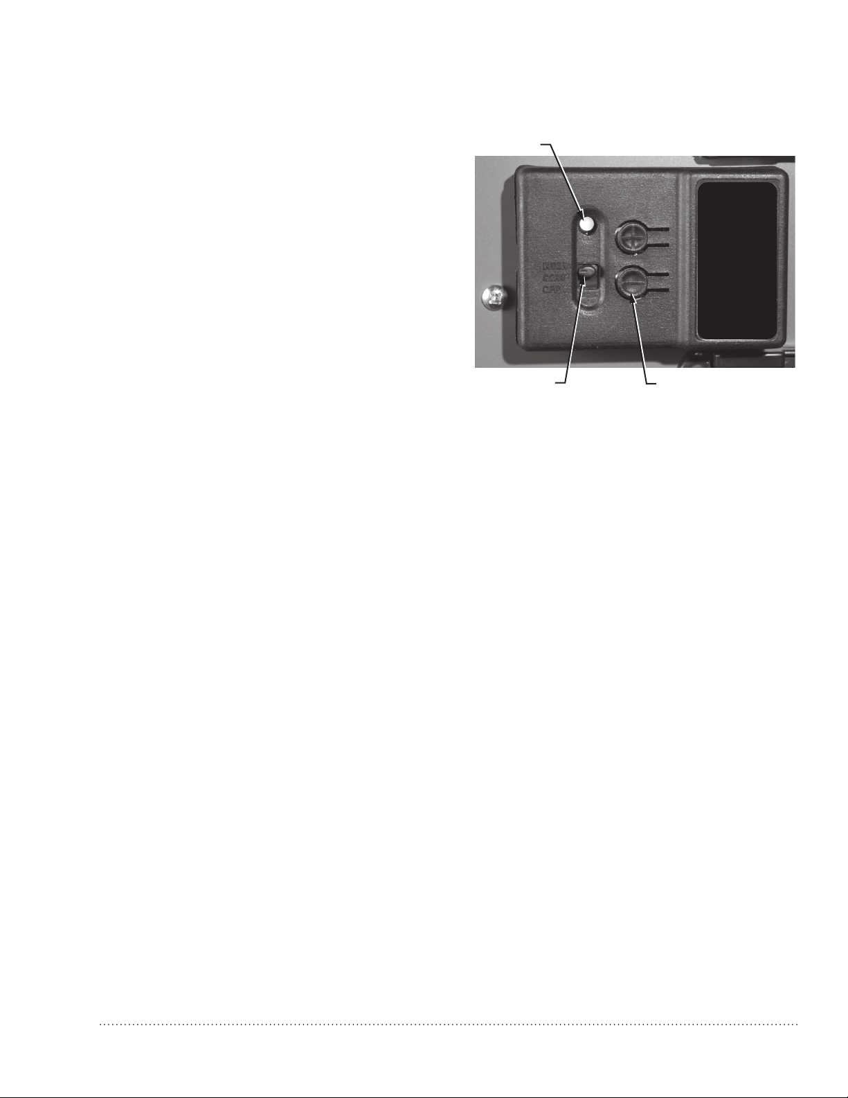
Control Panel
LED
The control panel has a 3-position selector switch
and “+” and “–” buttons for speed control. The
color of the LED indicator indicates the current
Speed
Control
function of the selector switch.
• GREEN LED = Mode Control (normal operating
Open for
Instructions
mode)
• YELLOW LED = Balancing Control
3-POSITION
SELECTOR SWITCH
SPEED CONTROL
BUTTONS (+ AND -)
M32371
Speed Control used as a Mode Control
When the LED indicator is green, the selector switch functions as a Mode Selector. The selections are:
• INTER (Intermittent): When the selector switch is in the intermittent position the unit will run only when
there is a call for ventilation by any external control. At that time the unit will run on high speed until the
condition is satised.
• CONT (Continuous): When the selector switch is in the continuous position the unit will run continuously
on low speed except when there is a call for override by any control.
• OFF: When the selector switch is in the off position the unit will not operate even when there’s a call for
ventilation by an external control.
• (+) and (–) buttons: Used to adjust the continuous speed setting.
Speed Control used as a Balancing Control
In balancing mode the LED indicator is yellow, and the selector switch functions as a Balancing Control
to set the high speed of the motors for balancing purposes (Fresh air, Exhaust air, and Both motors). The
selections are:
• INTER: Selects the exhaust air motor.
• CONT: Selects both exhaust and fresh air motors.
• OFF: Selects the fresh air motor.
NOTE: Continuous low speed is 50% of the set high speed.
NOTE: See Balancing Steps on page 7.
Speed Control used as a Motor Control
• + Button: Increase the speed of the selected motor.
• – Button: Decrease the speed of the selected motor.
NOTE: See Balancing Steps on page 7.
6
TrueFRESH™ Ventilation System 69-2481EF—01
Page 9
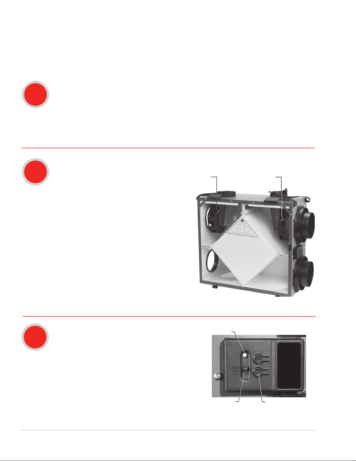
Balancing Steps
LED
NOTE: Perform the balancing steps with the HVAC equipment fan turned ON if the ERV/HRV unit
is ducted into an HVAC system.
1
2
a. Ensure that the speed control selector switch is in either the INTER or CONT position.
b. Press the (+) and (–) buttons simultaneously for 5 seconds until the LED indicator light turns
yellow, which indicates that you are in balancing mode.
When in balancing mode, the selector switch becomes the motor selector switch. The switch
positions become: INTER = Right motor (exhaust air), CONT = Both motors, and OFF = Left
motor (fresh air).
a. Use a pitot tube or ow station to measure the
air ow in the fresh air duct and exhaust air
FRESH AIR DUCT
(LEFT)
STALE AIR DUCT
(RIGHT)
duct.
b. Move the mode selector switch to adjust the
air ow in the duct with the higher reading.
INTER: Exhaust air (right)
OFF: Fresh air (left)
c. Press the (+) or (–) buttons to adjust the air
ow to the desired high speed setting.
d. Move the mode selector switch to the CONT
position (to proportionally adjust the speed of
both motors at the same time.
3
TrueFRESH™ Ventilation System 69-2481EF—01 7
a. Press the (+) and (–) buttons simultaneously to exit
balancing mode .
b. Indicator light turns green.
c. Continuous speed will be 50% of measured CFM.
3-POSITION
SELECTOR SWITCH
Speed
Control
Open for
Instructions
SPEED CONTROL
BUTTONS (+ AND -)
M32371
Page 10

Operating Your Wall Controls
Prestige™ (YTHX9321R5012) and Prestige™ IAQ Comfort
System (YTHX9421R5028)
• Controls both heating/cooling and ventilation.
• Wireless sensor for displaying outdoor temperature and humidity.
• Advanced ventilation programming includes economizing and extreme
condition shutdown.
• Maintenance and service reminders.
• High definition color display.
VisionPRO (TH8321U1097)and VisionPRO IAQ Total Comfort
System (YTH9421C1010)
• Controls both heating/cooling and ventilation.
• Sensor included for displaying outdoor temperature.
• Intuitive user interface for easy 7-day temperature programming.
• Easy-to-read backlit digital display.
• Maintenance and service reminders.
• Controls other indoor air quality equipment.
TrueIAQ Digital Control (DG115EZIAQ)
• Automatic adjustments maintain fresh air in home.
• Sensor for displaying outdoor temperature and humidity.
• Advanced ventilation programming includes economizing and extreme
condition shutdown.
• Maintenance and service reminders.
• Controls other indoor air quality equipment.
Manual Dehumidistat (H8908DSPST) and Automatic
Ventilation Controls (W8150A1000)
• Manual humidity control with intuitive comfort settings.
• Automatic W8150 ventilation control to ASHRAE standard, or for
continuous operation.
Boost Control Digital Timer (50053952-020)
• Ventilation boost control for 20/40/60 minutes.
8
TrueFRESH™ Ventilation System 69-2481EF—01
Page 11

Troubleshooting
CAUTION: Servicing the ERV/HRV unit with its electrical circuitry can cause
personal injury. Always make sure that power to the unit is disconnected prior to
making any connections. Failure to disconnect the power could result in electrical
shock. Service should only be performed by a qualified service technician.
Problem Recommended Troubleshooting Steps
ERV/HRV unit not running 1. Verify polarization of electrical receptacle.
2. Verify breaker in electrical box.
3. Verify that the external control or mode selector are activated to
call for ventilation.
4. Unplug the unit and verify that the external control(s) are wired
correctly to the wiring terminal block.
Air is too dry 1. Increase humidity level on the dehumidistat.
2. Switch ventilation mode from continuous to intermittent.
3. Install a humidier.
Air too humid 1. Reduce the humidity level on the controller.
2. Make sure that the clothes dryer is vented to the outdoors.
3. Wait for outside temperature to change. For example, it can be
very humid at times in the summer.
4. Verify balancing of the ERV/HRV unit (see Balancing Steps on
page 7).
LED on control panel remains
green
If the LED light on the ERV/HRV control panel remains green, the
motors do not energize, and the controls do not operate. This can
indicate that the Polarization in the main AC outlet is inverted
TrueFRESH™ Ventilation System 69-2481EF—01 9
Page 12

Maintenance of Your HRV/ERV
Quarterly or as Needed
Filters.
1
Annually or as Needed
1
Four times per year or as needed, vacuum the filters. Replace filters as needed.
Inside the Unit.
Once a year or as needed, clean the interior of the unit (walls and drain pan) with a mild and non
abrasive soap. It is recommended to use products that are environmentally-friendly.
Energy Recovery Core Unit (VNT5150E1000 and VNT5200E1000)
2
3
NOTE: See Cleaning Steps on page 11 for the above maintenance items.
Once a year or as needed, vacuum the four surfaces, let soak in warm water and mild soap for
15 minutes, then spray rinse and let dry.
Heat Recovery Core Unit (VNT5150H1000 and VNT5200H1000)
Once a year or as needed, vacuum the four surfaces, let soak in warm water and mild soap for
15 minutes, then spray rinse and let dry.
10
TrueFRESH™ Ventilation System 69-2481EF—01
Page 13

Cleaning Steps
1. Disconnect the AC power from the unit or the
wall.
2. Open the side door panel by opening the two
latches on the top of the side panel and lowering
the panel to its fully open position Remove both
lters from the top left and right sides of the
Core, then vacuum both lters.
Slide out the Core, and clean according to the
instructions on the previous page.
3. Clean inside of unit with a damp cloth and wipe
dry when nished.
TrueFRESH™ Ventilation System 69-2481EF—01 11
4. Replace the Core and the two lters, re-latch the
side panel, then reconnect the AC power to the
unit.
Page 14

5-Year Limited Warranty
Honeywell warrants this product to be free from defects in the workmanship or materials, under normal use
and service, for a period of five (5) years from the date of purchase by the consumer. If at any time during
the warranty period the product is determined to be defective or malfunctions, Honeywell shall repair or
replace it (at Honeywell’s option).
If the product is defective,
(i) return it, with a bill of sale or other dated proof of purchase, to the place from which you purchased it; or
(ii) call Honeywell Customer Care at 1-800-468-1502. Customer Care will make the determination whether
the product should be returned to the following address: Honeywell Return Goods, Dock 4 MN10-3860,
1885 Douglas Dr. N., Golden Valley, MN 55422, or whether a replacement product can be sent to you.
This warranty does not cover removal or reinstallation costs. This warranty shall not apply if it is shown by
Honeywell that the defect or malfunction was caused by damage which occurred while the product was in
the possession of a consumer.
Honeywell’s sole responsibility shall be to repair or replace the product within the terms stated above.
HONEYWELL SHALL NOT BE LIABLE FOR ANY LOSS OR DAMAGE OF ANY KIND, INCLUDING ANY
INCIDENTAL OR CONSEQUENTIAL DAMAGES RESULTING, DIRECTLY OR INDIRECTLY, FROM ANY
BREACH OF ANY WARRANTY, EXPRESS OR IMPLIED, OR ANY OTHER FAILURE OF THIS PRODUCT. Some
states do not allow the exclusion or limitation of incidental or consequential damages, so this limitation may
not apply to you.
THIS WARRANTY IS THE ONLY EXPRESS WARRANTY HONEYWELL MAKES ON THIS PRODUCT. THE
DURATION OF ANY IMPLIED WARRANTIES, INCLUDING THE WARRANTIES OF MERCHANTABILITY AND
FITNESS FOR A PARTICULAR PURPOSE, IS HEREBY LIMITED TO THE FIVE-YEAR DURATION OF THIS
WARRANTY. Some states do not allow limitations on how long an implied warranty lasts, so the above
limitation may not apply to you.
This warranty gives you specific legal rights, and you may have other rights which vary from state to state.
If you have any questions concerning this warranty, please write Honeywell Customer Relations, 1985
Douglas Drive, Golden Valley, MN 55422 or call 1-800-468-1502. In Canada, write Retail Products ON15-02H,
Honeywell Limited/Honeywell Limitée, 35 Dynamic Drive, Toronto, Ontario M1V4Z9.
Automation and Control Solutions
Honeywell International Inc.
1985 Douglas Drive North
Golden Valley, MN 55422
Honeywell Limited-Honeywell Limitée
35 Dynamic Drive
Toronto, Ontario M1V 4Z9
http://yourhome.honeywell.com
® U.S. Registered Trademark.
© 2011 Honeywell International Inc.
69-2481EF—01 M.S. 03-11
Printed in U.S.A.
Page 15

69-2481EF-01
Système de ventilation TrueFRESH™
GUIDE DU PROPRIÉTAIRE..
INCLUS DANS CETTE BOÎTE
B
TrueFRESH™ Ventilation System
INCLUDED IN THIS BOX
A1
B
TrueFRESH™ Ventilation System
INCLUDED IN THIS BOX
A1A1A2
B
C1 C2 C3 C4C5
TrueFRESH™ Ventilation System
OWNER’S GUIDE
INCLUDED IN THIS BOX
AAA
B
CCCCC
OPTIONAL CONTROLS SOLD SEPARATELY
TrueFRESH™ VNT5150H1000 or VNT5150E1000
TrueFRESH™ VNT5200H1000 or VNT5200E1000
A
Owner’s Guide
B
Optional Controls:
C
1. Vision Pro IAQ
OPTIONAL CONTROLS SOLD SEPARATELY
2. True IAQ
3. Dehumidistat H8908
4. 20/40/60 Minute Boost Control
5. W8150 Ventilation Control
69-2481EF-01
TrueFRESH™ VNT5150H1000 or VNT5150E1000
TrueFRESH™ VNT5200H1000 or VNT5200E1000
A2
Owner’s Guide
B
Optional Controls:
C
1. Vision Pro IAQ
2. True IAQ
3. Dehumidistat H8908
4. 20/40/60 Minute Boost Control
5. W8150 Ventilation Control
C1 C2 C3 C4 C5
OWNER’S GUIDE
OPTIONAL CONTROLS SOLD SEPARATELY
69-2481EF-01
TrueFRESH™ VNT5150H1000 or VNT5150E1000
A1
TrueFRESH™ VNT5200H1000 or VNT5200E1000
A2
Owner’s Guide
B
Optional Controls:
C
1. Vision Pro IAQ
2. True IAQ
3. Dehumidistat H8908
4. 20/40/60 Minute Boost Control
5. W8150 Ventilation Control
A1
C1 C2 C3 C4 C5
OWNER’S GUIDE
A2
RÉGULATEURS OPTIONNELS VENDUS SÉPARÉMENT
69-2481EF-01
TrueFRESH™ VNT5150H1000 ou VNT5150E1000
A1
TrueFRESH™ VNT5200H1000 ou VNT5200E1000
A2
Guide du propriétaire
B
Régulateurs optionnels :
C
1. Vision Pro IAQ
2. True IAQ
3. Déshumidistat H8908
4. Régulateur de suralimentation 20/40/60 minutes
5. Régulateur de ventilation W8150
A2
Page 16

Liste de vérification pour
l’installation
Inclus dans cette boîte
A1 TrueFRESH™ VNT5150H1000 ou VNT5150E1000
A2 TrueFRESH™ VNT5200H1000 ou VNT5200E1000
B Guide du propriétaire
Options de régulateurs (vendus séparément)
C1 Systèmes Prestige™ et Prestige™ IAQ Comfort
(sans l)
C2 TruelAQ
C3 Déshumidistat manuel H8908
C4 Régulateurs VisionPRO et VisionPRO IAQ
C5 Régulateur de ventilation W8150
Avertissement : l’installation doit être effectuée
par un technicien d’entretien qualié et
conformément aux codes locaux en vigueur.
Coupez l’alimentation vers l’appareil avant
d’installer ou de réparer cet appareil.
Un raccordement de cet appareil non conforme à
ces instructions peut endommager l’appareil ou les
régulateurs.
LES INSTRUCTIONS D’INSTALLATION DÉBUTENT À LA
PAGE 1
Page 17

Système de ventilation TrueFRESH™
FONCTIONNEMENT
Fonctionnement et fonction principale .....................2
Description .................................................................5
Panneau de commande ............................................. 6
Étapes de l’équilibrage ..............................................7
Utilisation de vos régulateurs muraux ....................... 8
DÉPANNAGE
Dépannage .................................................................9
ENTRETIEN
Entretien périodique ................................................. 10
Nettoyage .................................................................11
GARANTIE
Garantie limitée de 5 ans .........................................12
• Le produit est uniquement destiné aux applications résidentielles et doit être installé
conformément aux règlements et codes de construction et de sécurité nationaux et
locaux
BESOIN D’AIDE? Pour de l’assistance au sujet de ce produit, merci de consulter le site
http://yourhome.honeywell.com ou d’appeler le numéro gratuit du service à la clientèle de
?
Honeywell au 1-800-468-1502.
Lisez et conservez ces instructions.
® Marque de commerce déposée américaine. Brevets en instance. Copyright © 2011 Honeywell International Inc. Tous droits réservés.
Système de ventilation TrueFRESH™ 69-2481EF—01 1
Page 18

Fonctionnement et fonction principale
Votre système de ventilation a été conçu et mis au point pour améliorer la qualité de l’air intérieur en
réduisant en hiver le taux excessif d’humidité et de contaminants de votre habitation et en remplaçant
cet air par de l’air filtré provenant de l’extérieur. Lors des saisons plus froides, le noyau de récupération
de chaleur (noyau polypropylène) des unités récupère la chaleur issue de l’air rance sortant et utilise cette
chaleur pour tempérer l’air frais entrant, ce qui réduit le coût d’une ventilation efficace de votre maison au
cours de l’hiver.
REMARQUE : le processus inverse se déroule pendant les mois d’été.
Installation du système (exemples)
A
Salle de bains
Étage du régulateur
Rez-de-chaussée
Hotte d’alimentation en air frais
Hotte d’évacuation de l’air
Sous-sol
Système indépendant
VRC/VRE
2
Système de ventilation TrueFRESH™ 69-2481EF—01
Page 19

Fonctionnement et fonction principale
B
Salle de bains
Étage du régulateur
Rez-de-chaussée
Hotte d’alimentation en air frais
Hotte d’évacuation de l’air
Sous-sol
Évacuation à la source et alimentation dans le circuit de retour
VRC/VRE
Système
d’air forcé
Système de ventilation TrueFRESH™ 69-2481EF—01 3
Page 20

Fonctionnement et fonction principale
C
Salle de bains
Étage du régulateur
Rez-de-chaussée
Hotte d’alimentation en air frais
Hotte d’évacuation de l’air
Sous-sol
Évacuation et alimentation dans le circuit de retour
VRC/VRE
Système
d’air forcé
4
Système de ventilation TrueFRESH™ 69-2481EF—01
Page 21

Description
Système de ventilation avec mode de
recirculation
A. Air frais provenant de l’extérieur
B. Évacuation d’air vers l’extérieur
C. Évacuation d’air de l’intérieur
D. Air frais vers l’intérieur
C
A
B
• Air frais provenant de l’orifice extérieur (A)
entrée d’air frais extérieur.
• Évacuation d’air vers l’orifice extérieur (B)
sortie pour l’air rance, humide et contaminé vers
l’extérieur après transfert de sa chaleur au noyau
de récupération.
• Évacuation d’air vers l’orifice intérieur (C)
évacue l’air rance, humide et contaminé vers
l’extérieur à partir de plusieurs emplacements
de la maison ou à partir de l’air de retour du
système d’air forcé, avant de traverser le noyau
de récupération de chaleur. Ex : salle de bains,
salle de lavage, etc.
• Air frais vers l’orifice intérieur (D) introduit
et répartit l’air propre et frais dans votre
maison. Les orifices d’air frais de la maison
sont normalement installés dans les zones de
vie principales ou dans le conduit de retour/
alimentation du système d’air forcé. Ex : salon,
chambres à coucher, salles de jeux, etc.
• Panneau de commande sélectionne vos modes
de ventilation (OFF, CONT ou INTER) et permet
de régler les débits des flux d’air continus :
Augmentation (+)/Diminution (-).
• Filtres synthétiques capturent les particules
les plus grosses et protègent votre noyau
de récupération de chaleur d’obstructions
potentielles dues à ces particules.
D
• Noyau de récupération de chaleur un
noyau de type polypropylène à flux croisé
est utilisé pour transférer la chaleur entre les
flux d’évacuation et d’admission d’air sans
permettre une contamination ou un mélange
des deux flux d’air, afin de maximiser son
efficacité et améliorer la qualité de l’air intérieur.
• Bac de récupération de condensation
et flexible de vidange : capture l’eau
qui s’accumule au cours des séquences
de transfert de chaleur et de dégivrage en
automne, en hiver et au début du printemps.
Le flexible de vidange est connecté au bac de
récupération et sert à évacuer l’accumulation
d’eau. Il est normal de ne pas trouver de
condensation dans le bac de récupération ou le
flexible de vidange au cours des mois d’été.
• Séquence de dégivrage automatique les
unités VRE et VRC sont dotées d’une fonction
de dégivrage automatique destinée à éliminer
toute accumulation de glace sur le noyau. Un
dégivrage automatique est déclenché toutes les
heures lorsque la température de l’alimentation
en air frais est inférieure ou égale à 23 °F
(-5 °C).
- Le cycle de dégivrage s’effectue en
désactivant le ventilateur d’alimentation
tout en continuant à activer le ventilateur
d’évacuation.
- La vitesse du ventilateur d’évacuation est
ajustée proportionnellement à la température
extérieure, le ventilateur fonctionnant
initialement à basse vitesse.
- Lorsque la température extérieure continue à
chuter, la vitesse du ventilateur d’évacuation
augmente, et le ventilateur fonctionne à la
vitesse maximale lorsque la température
extérieure est inférieure ou égale à -4 °F
(-20 °C).
- Le cycle de dégivrage se compose de 4
minutes de désactivation du ventilateur
d’alimentation, suivies de 40 minutes de
fonctionnement normal continu.
- Les cycles de dégivrage se poursuivent tant
que la température est inférieure ou égale à
23 °F (-5 °C).
• Air frais provenant de l’orifice extérieur (A)
entrée d’air frais extérieur.
Système de ventilation TrueFRESH™ 69-2481EF—01 5
Page 22

Panneau de commande
DEL
Le panneau de commande comporte un sélecteur
à trois positions et des touches « + » et « – » pour
la régulation la vitesse. La couleur du voyant DEL
indique la fonction actuelle du sélecteur.
• DEL VERTE = Commande de mode (mode de
Speed
Control
Open for
Instructions
fonctionnement normal)
• DEL JAUNE = Commande d’équilibrage
SÉLECTEUR À
3 POSITIONS
TOUCHES DE RÉGULATION
DE LA VITESSE (+ ET -)
MF32371
Régulateur de vitesse utilisé comme commande de mode
Lorsque le voyant DEL est vert, le sélecteur fonctionne comme sélecteur de mode. Les sélections sont :
• INTER (Intermittent) : lorsque le sélecteur est en position intermittente, l’unité fonctionne uniquement en
cas d’appel de ventilation provenant d’un régulateur externe. À ce moment l’unité fonctionne à vitesse
élevée jusqu’à ce que la condition soit satisfaite.
• CONT (Continu) : lorsque le sélecteur est en position continue, l’unité fonctionne continuellement à basse
vitesse sauf en cas d’appel d’annulation provenant d’un régulateur.
• OFF (Arrêt) : lorsque le sélecteur est en position d’arrêt, l’unité ne fonctionne pas même en cas d’appel
de ventilation provenant d’un régulateur externe.
• Touches (+) et (–) : utilisées pour ajuster le réglage de vitesse continue.
6
Régulateur de vitesse utilisé comme commande d’équilibrage
En mode d’équilibrage le voyant DEL est jaune, et le sélecteur fonctionne en tant que commande
d’équilibrage pour régler la vitesse élevée des moteurs aux fins d’équilibrage (Air frais, Air d’évacuation et
Deux moteurs). Les sélections sont :
• INTER: sélectionne le moteur d’air d’évacuation.
• CONT: sélectionne à la fois les moteurs d’évacuation et d’air frais.
• OFF: sélectionne le moteur d’air frais.
REMARQUE : la basse vitesse continue représente 50 % de la vitesse élevée déterminée.
REMARQUE : voir les Étapes de l’équilibrage à la page 7.
Régulateur de vitesse utilisé comme commande de moteur
• Touche + : augmente la vitesse du moteur sélectionné.
• Touche – : diminue la vitesse du moteur sélectionné.
REMARQUE : voir les Étapes de l’équilibrage à la page 7.
Système de ventilation TrueFRESH™ 69-2481EF—01
Page 23

Étapes de l’équilibrage
DEL
REMARQUE : exécutez les étapes de l’équilibrage avec le ventilateur de l’équipement CVCA
activé si l’unité VRE/VRC est connectée à un système CVCA.
1
2
a. Vériez si le sélecteur de commande de vitesse est en position INTER ou CONT.
b. Pressez simultanément les touches (+) et (–) pendant 5 secondes jusqu’à ce que le voyant DEL
devienne jaune, ce qui indique le passage en mode d’équilibrage.
En mode d’équilibrage, le sélecteur devient un sélecteur de moteur. Les positions du
sélecteur deviennent : INTER = moteur droit (air d’évacuation), CONT = deux moteurs, et
OFF = moteur gauche (air frais).
a. Utilisez un tube de Pitot ou une station
de débit pour mesurer le débit d’air dans
CONDUIT D’AIR FRAIS
(GAUCHE)
CONDUIT D’AIR RANCE
(DROIT)
le conduit d’air frais et le conduit d’air
d’évacuation.
b. Déplacez le sélecteur de mode pour ajuster le
débit d’air dans le conduit présentant la valeur
la plus élevée. INTER : Air d’évacuation (droit)
OFF : Air frais (gauche)
c. Pressez les touches (+) ou (–) pour ajuster le
débit d’air au réglage de vitesse élevée désiré.
d. Déplacez le sélecteur de mode en position
CONT (pour ajuster proportionnellement la
vitesse des deux moteurs simultanément).
3
a. Pressez simultanément les touches (+) et (–) pour
sortir du mode d’équilibrage.
b. Le voyant devient vert.
c. La vitesse continue sera égale à 50 % de la
Speed
Control
Open for
Instructions
valeur pi³/min mesurée.
SÉLECTEUR À
3 POSITIONS
Système de ventilation TrueFRESH™ 69-2481EF—01 7
TOUCHES DE RÉGULATION
DE LA VITESSE (+ ET -)
MF32371
Page 24

Utilisation de vos régulateurs muraux
Systèmes Prestige™ (YTHX9321R5012) et Prestige™ IAQ
Comfort (YTHX9421R5028)
• Régule à la fois le chauffage/refroidissement et la ventilation.
• Capteur sans fil pour l’affichage de la température et de l’humidité
extérieures.
• La programmation de ventilation avancée inclut un programme
économique et l’arrêt en cas de condition extrême.
• Rappels de maintenance et d’entretien.
• Afficheur couleur haute définition.
Systèmes VisionPRO (TH8321U1097) et VisionPRO IAQ Total
Comfort (YTH9421C1010)
• Régule à la fois le chauffage/refroidissement et la ventilation.
• Capteur inclus pour l’affichage de la température extérieure.
• Interface utilisateur intuitive pour une programmation facile de la
température sur 7 jours.
• Afficheur numérique rétroéclairé facile à lire.
• Rappels de maintenance et d’entretien.
• Régule un autre équipement de qualité de l’air intérieur.
Régulateur numérique TrueIAQ (DG115EZIAQ)
• Les ajustements automatiques assurent la conservation d’un air frais
dans la maison.
• Capteur pour l’affichage de la température et de l’humidité extérieures.
• La programmation de ventilation avancée inclut un programme
économique et l’arrêt en cas de condition extrême.
• Rappels de maintenance et d’entretien.
• Régule un autre équipement de qualité de l’air intérieur.
Déshumidistat manuel (H8908DSPST) et commandes de
ventilation automatiques (W8150A1000)
• Régulateur d’humidité manuel avec réglages de confort intuitifs.
• Régulateur de ventilation automatique W8150 conforme aux normes
ASHRAE ou pour un fonctionnement en continu.
Minuterie numérique de régulation de la suralimentation
(50053952-020)
• Régule la suralimentation de la ventilation pendant 20/40/60 minutes.
8
Système de ventilation TrueFRESH™ 69-2481EF—01
Page 25

Dépannage
MISE EN GARDE : une intervention sur une unité VRE/VRC et son circuit électrique
peut causer des blessures. Veillez toujours à ce que l’unité soit déconnectée
avant d’effectuer une correction. Ne pas déconnecter la source d’alimentation
peut causer un choc électrique. L’intervention ne doit être effectuée que par un
technicien d’entretien qualifié.
Problème Étapes de dépannage recommandées
L’unité VRE/VRC ne fonctionne
pas
L’air est trop sec 1. Augmentez le niveau d’humidité au déshumidistat.
1. Vériez la polarité du réceptacle électrique.
2. Vériez le disjoncteur dans le boîtier électrique.
3. Vériez si le régulateur externe ou le sélecteur de mode sont
activés pour un appel de ventilation.
4. Débranchez l’unité et vériez si le(s) régulateur(s) externe(s) sont
correctement câblé(s) au bloc de bornes de câblage.
2. Commutez le mode de ventilation de continu à intermittent.
3. Installez un humidicateur.
L’air est trop humide 1. Réduisez le niveau d’humidité sur le régulateur.
2. Vériez si le séchoir dispose d’une ventilation vers l’extérieur.
3. Attendez que la température extérieure se modie. Par exemple,
l’humidité peut parfois être très élevée en été.
4. Vériez l’équilibrage de l’unité VRE/VRC (voir Étapes de
l’équilibrage à la page 7).
La DEL du panneau de commande
reste verte
Si la diode du panneau de commande VRE/VRC reste verte,
les moteurs ne sont pas mis sous tension et les régulateurs ne
fonctionnent pas. Ceci peut indiquer que la polarité de la prise de
courant CA principale est inversée
Système de ventilation TrueFRESH™ 69-2481EF—01 9
Page 26

Entretien de votre VRH/VRE
Tous les trimestres ou en fonction des besoins
Filtres.
1
Tous les ans ou en fonction des besoins
1
Quatre fois par an ou en fonction des besoins, aspirez les filtres. Remplacez au besoin les filtres.
Intérieur de l’unité.
Une fois par an ou en fonction des besoins, nettoyez l’intérieur de l’unité (parois et bac de
récupération) à l’aide d’un savon doux et non abrasif. Il est recommandé d’utiliser un produit
respectant l’environnement.
Unité du noyau de récupération d’énergie (VNT5150E1000 et VNT5200E1000)
2
3
REMARQUE : voir les Étapes de nettoyage de la page 11 pour les points d’entretien ci-dessus.
Une fois par an ou en fonction des besoins, aspirez les quatre surfaces, laissez-les tremper dans
une solution d’eau chaude et de savon doux pendant 15 minutes, puis rincez et laissez sécher.
Unité du noyau de récupération de chaleur (VNT5150H1000 et VNT5200H1000)
Une fois par an ou en fonction des besoins, aspirez les quatre surfaces, laissez-les tremper dans
une solution d’eau chaude et de savon doux pendant 15 minutes, puis rincez et laissez sécher.
10
Système de ventilation TrueFRESH™ 69-2481EF—01
Page 27

Étapes de nettoyage
1. Déconnectez la prise de courant CA de l’unité ou
du mur.
2. Ouvrez le panneau du volet latéral en ouvrant
les deux loquets situés au sommet du panneau
latéral et en abaissant le panneau en position
d’ouverture totale. Retirez les deux ltres des
côtés supérieurs gauche et droit du noyau, puis
aspirez les deux ltres. Extrayez le noyau et
nettoyez-le conformément aux instructions de la
page précédente.
3. Nettoyez l’intérieur de l’unité à l’aide d’un chiffon
humide et séchez-le lorsque vous avez terminé.
Système de ventilation TrueFRESH™ 69-2481EF—01 11
4. Replacez le noyau et les deux ltres, verrouillez
le panneau latéral et reconnectez la prise de
courant CA à l’unité.
Page 28

Garantie limitée de 5 ans
Honeywell garantit ce produit contre tout vice de fabrication ou de matière dans la mesure où il en est
fait une utilisation et un entretien convenables, et ce, pour cinq (5) ans à partir de la date d’achat par le
consommateur. En cas de défectuosité ou de mauvais fonctionnement pendant la période de garantie,
Honeywell remplacera ou réparera le produit (au gré de Honeywell).
Si le produit est défectueux,
(i) le retourner, accompagné d’une preuve d’achat indiquant la date d’achat, au détaillant auprès de qui il a
été acheté, ou
(ii) s’adresser aux Services à la clientèle de Honeywell en composant le 1-800-468-1502. Les Services à la
clientèle détermineront alors si le produit doit être retourné à l’adresse suivante : Honeywell Return Goods,
Dock 4 MN10-3860, 1885 Douglas Dr. N., Golden Valley, MN 55422, ou si un produit de remplacement peut
vous être expédié.
La présente garantie ne couvre pas les frais de retrait ou de réinstallation. La présente garantie ne
s’appliquera pas s’il est démontré que la défectuosité ou le mauvais fonctionnement est dû à un
endommagement du produit alors que le consommateur l’avait en sa possession.
La responsabilité de Honeywell se limite à réparer ou à remplacer le produit conformément aux
modalités susmentionnées. HONEYWELL N’EST EN AUCUN CAS RESPONSABLE DES PERTES OU
DOMMAGES, Y COMPRIS LES DOMMAGES INDIRECTS OU ACCESSOIRES DÉCOULANT DIRECTEMENT
OU INDIRECTEMENT D’UNE VIOLATION QUELCONQUE D’UNE GARANTIE, EXPRESSE OU TACITE,
APPLICABLE AU PRÉSENT PRODUIT NI DE TOUTE AUTRE DÉFECTUOSITÉ DU PRÉSENT PRODUIT.
Certaines provinces ne permettent pas l’exclusion ou la restriction des dommages indirects et, par
conséquent, la présente restriction peut ne pas s’appliquer.
CETTE GARANTIE EST LA SEULE GARANTIE EXPRESSE QUE HONEYWELL OFFRE POUR CE PRODUIT.
LA DURÉE DE TOUTE GARANTIE IMPLICITE, INCLUANT LES GARANTIES DE QUALITÉ MARCHANDE OU
D’ADAPTATION À UNE UTILISATION PARTICULIÈRE, EST LIMITÉE PAR LES PRÉSENTES À LA PÉRIODE
DE CINQ ANS DE LA PRÉSENTE GARANTIE. Certaines provinces ne permettent pas de limiter la durée des
garanties tacites et, par conséquent, la présente limitation peut ne pas s’appliquer.
La présente garantie donne au consommateur des droits légaux spécifiques et peut-être certains autres
droits qui peuvent varier d’une province à l’autre.
Pour toute question concernant la présente garantie, prière d’écrire aux Services à la clientèle de Honeywell
à l’adresse suivante : Honeywell Customer Relations, 1985 Douglas Drive, Golden Valley, MN 55422, ou
encore composer le 1-800-468-1502. Au Canada, prière de s’adresser au service des Produits de détail,
Honeywell Limited/Honeywell Limitée.
Solutions de régulation et d’automatisation
Honeywell International Inc.
1985 Douglas Drive North
Golden Valley, MN 55422
http://yourhome.honeywell.com
Honeywell Limited-Honeywell Limitée
35 Dynamic Drive
Toronto, Ontario M1V 4Z9
® Marque déposée américaine.
© 2011 Honeywell International Inc.
69-2481EF—01 M.S. 03-11
Imprimé aux États-Unis.
 Loading...