

Page 1
Installation
Guide
VisionPRO®IAQ
Equipment Interface Module
English: Page 1 • Français: Page 6 • Español: Página 11
For up to 4 Heat/2 Cool systems with Honeywell TH9421C or equivalent.
System Types
• Gas, oil, or electric heat with air
conditioning
• Warm air, hot water, highefficiency furnaces, heat pumps,
steam, gravity
• Heat only — two-wire systems,
power to open and close zone
valves (Series 20), and normallyopen zone valves
• Heat only with fan
• Cool only
• Variable speed systems
Must be installed by a trained, experienced technician
• Read these instructions carefully. Failure to follow these instructions
can damage the product or cause a hazardous condition.
CAUTION: ELECTRICAL HAZARD
Can cause electrical shock or equipment damage. Disconnect power before
beginning installation.
MERCURY NOTICE
If this product is replacing a control that contains mercury in a sealed tube, do not
place the old control in the trash. Contact your local waste management authority for
instructions regarding recycling and proper disposal.
® U.S. Registered Trademark.
Copyright © 2006 Honeywell International Inc.
All rights reserved.
Page 2
VisionPRO®IAQ Equipment Interface Module
Installation
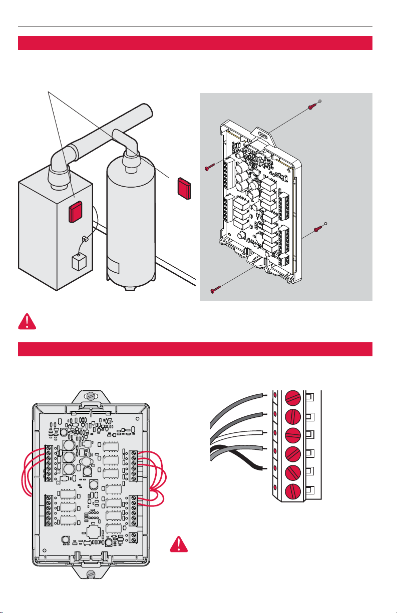
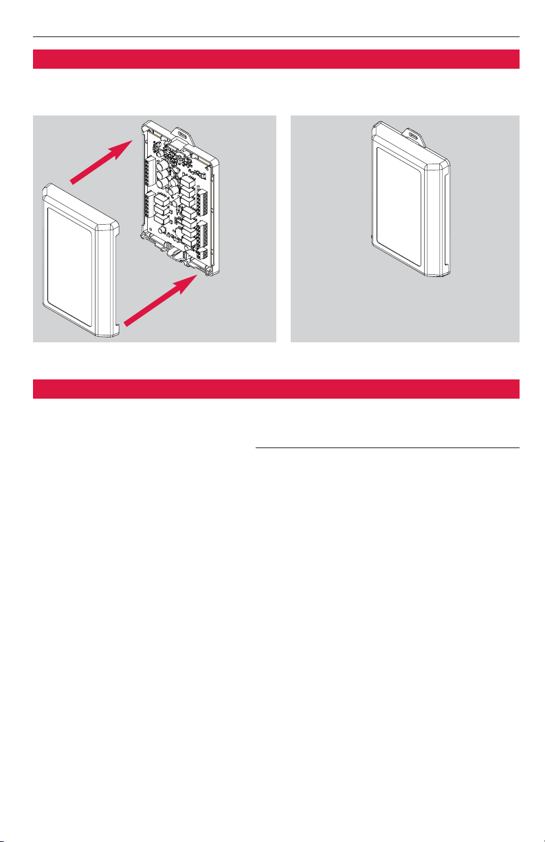
1 Remove cover from Equipment Interface Module (EIM).
2 Select location and mount EIM as shown below.
Wall anchor
Drill 3/16” holes
for drywall. Drill
7/32” holes for
plaster.
Furnace/air handler Water heater
CAUTION: This product may be damaged if mounted inside HVAC equipment. Install
only on the outside of HVAC equipment.
Mounting screw
Wiring
Connect wires as shown below (see wiring guides on following pages).
All wiring must comply with local electrical
codes and ordinances.
2
Page 3
English: Page 1 • Français: Page 6 • Español: Página 11
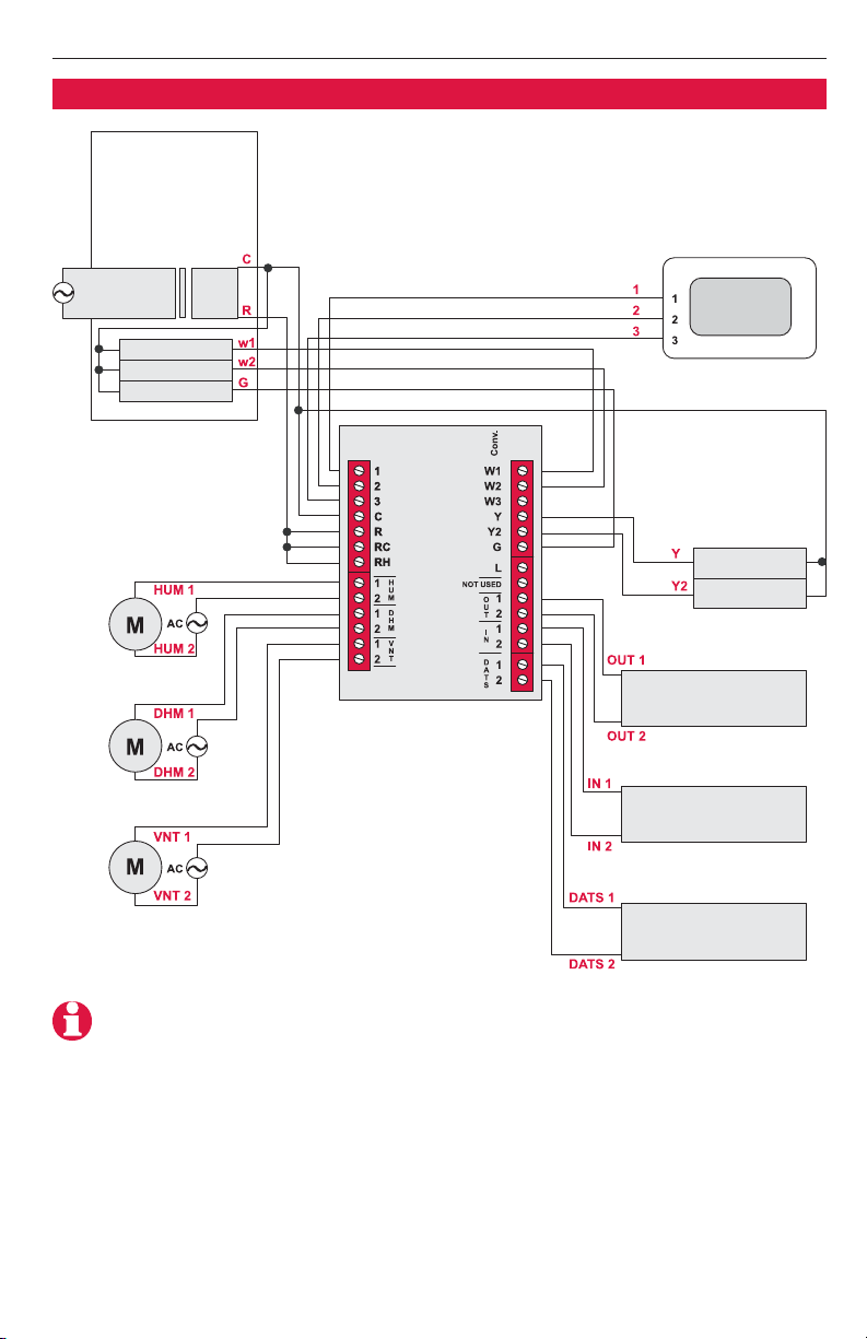
Wiring guide — conventional systems
FURNACE
Transformer
Stage 1 heat
Stage 2 heat
Fan
Humidifier
Dehumidifier
Ventilation
THERMOSTAT
24Vac120Vac
Air conditioning
compressors
Stage 1
Stage 2
Temperature sensor
EQUIPMENT INTERFACE
MODULE
(outdoor)
Temperature sensor
(indoor)
Discharge air
temperature sensor
NOTE: Check other equipment manuals to verify proper terminal connections.
3
Page 4
VisionPRO®IAQ Equipment Interface Module
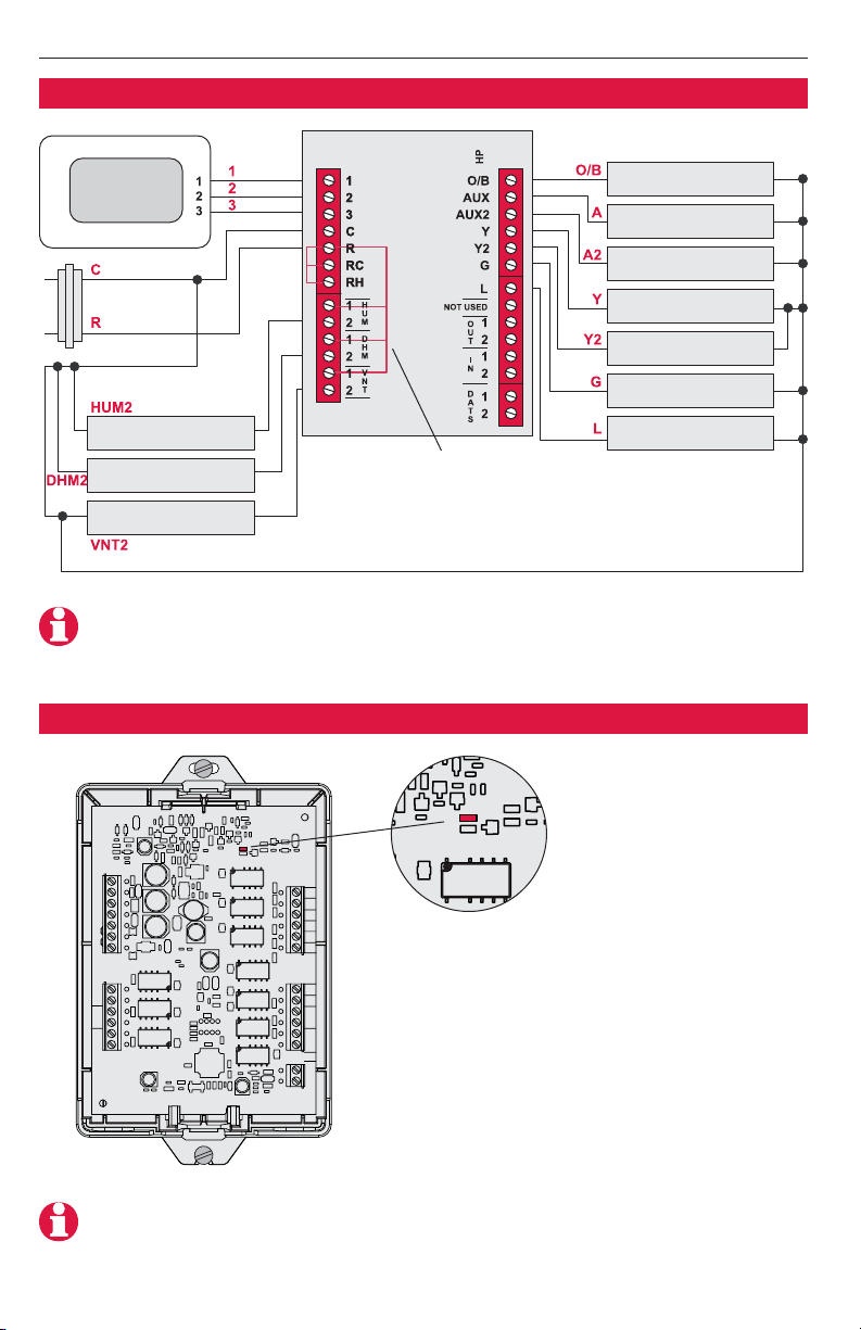
EIM wiring guide — heat pump systems
THERMOSTAT
Bypass humidifier
Low speed fan
Ventilator
EQUIPMENT INTERFACE
MODULE
Jumpers
NOTE: Check other equipment manuals to verify proper terminal connections.
Restore power & check operation
Changeover relay
Backup heat
(gas/electric)
Backup heat
(gas/electric)
Compressor
(stage 1)
Compressor
(stage 2)
Fan relay
System monitor
LED
Restore power and check LED:
• LED blinks rapidly: Normal information transfer.
• LED blinks once: Incoming message to EIM.
• LED blinks continuously: Wiring problem. Check
wiring to terminals 1, 2, 3.
• LED always off: Wiring problem. Check wiring to
terminals 1, 2, 3.
• LED always on: EIM may need replacement.
NOTE: It is normal for the LED to blink continuously during startup, and while checking
equipment status (Auto Discover mode).
4
Page 5
English: Page 1 • Français: Page 6 • Español: Página 11
Replace EIM cover
Place cover on EIM, then push gently until it snaps into place.
Specifications
Temperature Ranges
• Heat: 40° to 90°F (4.5° to 32°C)
• Cool: 50° to 99°F (10° to 37°C)
Operating Ambient Temperature
• 0° to 120°F (-18° to 49°C)
Shipping Temperature
• -30° to 150°F (-34° to 66°C)
Operating Relative Humidity
• 5% to 90% (non-condensing)
Physical Dimensions
• 4-9/16” H x 6” W x 1-3/8” D
• 116 mm H x 152 mm W x 35 mm D
Electrical Ratings
Terminal Voltage (50/60Hz) Running Current
W Heating 20-30 Vac 0.02-1.0 A
W2 Heating 20-30 Vac 0.02-1.0 A
W3 Heating 20-30 Vac 0.02-1.0 A
Y Cooling 20-30 Vac 0.02-1.0 A
Y2 Cooling 20-30 Vac 0.02-1.0 A
Aux Auxiliary heat 20-30 Vac 0.02-1.0 A
Aux2 Auxiliary heat 20-30 Vac 0.02-1.0 A
G Fan 20-30 Vac 0.02-1.0 A
O/B Changeover 20-30 Vac 0.02-1.0 A
5
Page 6

Guide
d’installation
VisionPRO®IAQ
Equipment Interface Module
English: Page 1 • Français: Page 6 • Español: Página 11
Pour installations comportant 4 circuits de chauffage/2 circuits de climatisation
avec Honeywell TH9421C ou équivalent.
Types d’installations
• Chauffage au gaz, au mazout ou
électrique avec climatisation
• Chaudières à haut rendement à air
chaud, eau chaude, thermopompes,
vapeur, calorifères
• Installation à deux fils chauffage
seulement, alimentation pour ouvrir
et fermer les valves de zone (Série
20) et vannes de zone normalement
ouvertes
• Chauffage seulement avec ventilateur
• Climatisation seulement
• Systèmes variables de vitesse
Il est impératif de faire réaliser l’installation par un technicien chevronné
• Lisez attentivement les présentes consignes. La non observation de celles-ci
risque d’endommager le produit ou de présenter des dangers.
MISE EN GARDE : RISQUE ÉLECTRIQUE
Peut provoquer des secousses électriques ou endommager le matériel.
Coupez l’alimentation avant d’entreprendre l’installation.
AVIS CONCERNANT LE MERCURE
Si ce produit remplace un dispositif de régulation contenant une ampoule de
mercure, ne placez pas ce dernier dans les ordures. Contactez l'agence de gestion
des déchets de la localité pour connaître les règlements concernant le recyclage
et la mise au rebut.
Copyright © 2006 Honeywell International Inc.
® U.S. Marque déposée
Tous droits réservés
Page 7

English: Page 1 • Français: Page 6 • Español: Página 11
Installation
1 Enlevez la couverture de Equipment Interface Module (EIM).
2 Choisissez l'endroit et montez le EIM comme indiqué ci-dessous.
Chevilles murales
Percez des trous
de 3/16 po dans
une cloison
sèche. Percez
des trous de
7/32 po dans du
plâtre.
Chaudière/traiteur d'air Chauffe-eau
ATTENTION : Pour éviter des dommages, n'installez pas ce produit à l'intérieur
d'équipement de la HVAC. Installez seulement sur l'extérieur de l'équipement de la HVAC.
Vis de montage
Câblage
Reliez les fils comme montrés ci-dessous (voir les guides de câblage aux pages suivantes).
Tout le câblage doit être conforme aux codes
et aux ordonnances électriques locaux.
7
Page 8

VisionPRO®IAQ Equipment Interface Module
Guide de câblage — installations traditionnelles
CHAUDIÈRE
Transformateur
Chauff. étage 1
Chauff. étage 2
Ventilateur
Humidificateur
Déshumidificateur
Ventilation
THERMOSTAT
24Vac120Vac
Compresseurs
de climatisation
Étage 1
Étage 2
Sonde de température
EQUIPMENT INTERFACE
MODULE
(extérieure)
Sonde de température
(intérieure)
Vérifiez d'autres manuels d'équipement pour vérifier
les raccordements terminaux appropriés.
8
Sonde de température
de l'air de décharge
Page 9

English: Page 1 • Français: Page 6 • Español: Página 11
Guide de câblage — installations à thermopompe
THERMOSTAT
Humidificateur
de déviation
Ventilateur
à vitesse réduite
Ventilation
EQUIPMENT INTERFACE
MODULE
Vérifiez d'autres manuels d'équipement pour vérifier
les raccordements terminaux appropriés.
Vérifiez l'opération
Cavalier
Relais d’inversion
Chauff. de secours
(gaz/électrique)
Chauff. de secours
(gaz/électrique)
Compresseur
(Étage 1)
Compresseur
(Étage 2)
Relais ventilateur
Moniteur de système
LED
Reconstituerez l'énergie électrique &
vérifiez l'opération:
• La lumière clignote rapidement : Transfert de
l'information normal.
• Clignotements de lumière une fois : Message
entrant à EIM.
• La lumière clignote sans interruption :
Problème de câblage. Vérifiez le câblage aux
bornes 1, 2, 3.
• Lumière toujours au loin : Problème de câblage.
Vérifiez le câblage aux bornes 1, 2, 3.
• Lumière toujours dessus : EIM peut avoir besoin
de remplacement.
Il est normal que la LED clignote sans interruption pendant le démarrage,
et tout en vérifiant le statut d'équipement (le mode Auto Discover).
9
Page 10

VisionPRO®IAQ Equipment Interface Module
Remplacez la couverture d'EIM
Placez la couverture sur EIM, puis poussez doucement jusqu'à ce qu'il se
casse dans l'endroit.
Caractéristiques techniques
Gammes de température
• Chauffage : 40° à 90°F (4.5° à 32°C)
• Climatisation : 50° à 99°F (10° à 37°C)
Température ambiante de fonctionnement
• 0° à 120°F (-18° à 49°C)
Température d’expédition
• -30° à 150°F (-34° à 66°C)
Humidité relative de fonctionnement
• 5% à 90% (sin condensación)
Dimensions
• 4-9/16” H x 6” L x 1-3/8” Ép
• 116 mm H x 152 mm L x 35 mm Ép
Caractéristiques électriques
Borne Tension (50/60Hz) Courant
W Chauffage 20-30 Vca 0,02-1,0 A
W2 Chauffage 20-30 Vca 0,02-1,0 A
W3 Chauffage 20-30 Vca 0,02-1,0 A
Y Climatisation 20-30 Vca 0,02-1,0 A
Y2 Climatisation 20-30 Vca 0,02-1,0 A
Aux Chauffage aux. 20-30 Vca 0,02-1,0 A
Aux2 Chauffage aux. 20-30 Vca 0,02-1,0 A
G Ventilateur 20-30 Vca 0,02-1,0 A
O/B Inversion 20-30 Vca 0,02-1,0 A
10
Page 11

Guía de
instalación
VisionPRO®IAQ
Equipment Interface Module
English: Page 1 • Français: Page 6 • Español: Página 11
Para hasta 4 sistemas de calefacción/2 de refrigeración con Honeywell TH9421C o equivalente.
Tipos de sistemas
• Calefacción a gas, petróleo o
eléctrica con aire acondicionado
• Aire caliente, agua caliente, estufas
de alta eficiencia, bombas de
calefacción, vapor, gravedad
• Sólo calefacción, sistemas de
doble cableado, alimentación de
energía para abrir y cerrar válvulas
de zona (serie 20) y abrir normalmente válvulas de zona
• Sólo calefacción con ventilador
• Sólo refrigeración
• Sistemas variables de la velocidad
Debe instalarlo un técnico capacitado y con experiencia
• Lea atentamente estas instrucciones. Si las ignora, podría dañarse el
producto o generarse condiciones de peligro.
PRECAUCIÓN: PELIGRO ELÉCTRICO
Puede causar descarga eléctrica o daño del equipo. Desconecte la alimentación de
energía antes de iniciar la instalación.
AVISO DE MERCURIO
Si este producto reemplaza a un control que contiene mercurio en un tubo sellado,
no arroje el control viejo a la basura. Comuníquese con la autoridad local de disposición de desechos para recibir instrucciones sobre reciclado y eliminación correcta.
® Marca registrada en EE.UU.
Copyright © 2006 Honeywell International Inc.
Todos los derechos reservados.
Page 12

VisionPRO®IAQ Equipment Interface Module
Instalación
1 Quite la cubierta de Equipment Interface Module (EIM).
2 Seleccione la localización y monte EIM como se muestra a continuación.
Soportes de pared
Orificios de
taladro de 3/16”
para mampostería en seco.
Orificios de
taladro de 7/32”
para yeso.
Estufa/tratante del aire Calentador de agua
PRECAUCIÓN: Para evitar daño, no instale este producto dentro del equipo de la HVAC.
Instale solamente en el exterior del equipo de la HVAC.
Tornillos de montaje
Cableado
Conecte los cables según lo demostrado abajo (ver las guías de cableado
en las páginas siguientes).
Todo el cableado debe conformarse con
códigos y ordenanzas eléctricos locales.
12
Page 13

English: Page 1 • Français: Page 6 • Español: Página 11
Guía para el cableado — sistemas convencionales
ESTUFA
Transformador
Calor (etapa 1)
Calor (etapa 2)
Ventilador
Humidificador
Deshumidificador
Ventilación
TERMOSTATO
24Vac120Vac
Compresores
del aire
acondicionado
Etapa 1
Etapa 2
Sensor de temperatura
EQUIPMENT INTERFACE
MODULE
(exterior)
Sensor de temperatura
(interior)
NOTA: Consulte otros manuales del equipo para verificar
conexiones terminales apropiadas.
13
Sensor de temperatura
del aire de la descarga
Page 14

VisionPRO®IAQ Equipment Interface Module
Guía para el cableado — sistemas de bombeo de calefacción
TERMOSTATO
Humidificador
de puente
Ventilador bajo
de la velocidad
Ventilación
EQUIPMENT INTERFACE
MODULE
Empalme
NOTA: Consulte otros manuales del equipo para verificar
conexiones terminales apropiadas.
Verifique la operación
Relais del cambio
Calor de reserva
(gas/eléctrica)
Calor de reserva
(gas/eléctrica)
Compresor
(etapa 1)
Compresor
(etapa 2)
Relais del ventilador
Monitor del sistema
LED
Reactivaron corriente eléctrica y verifique la
operación:
• La luz centelleo rápidamente: Transmisión
informativa normal.
• Centelleos de la luz una vez: Mensaje entrante
a EIM.
• La luz centelleo continuamente: Problema del
cableado. Compruebe el cableado a los terminales
1, 2, 3.
• Luz siempre apagado: Problema del cableado.
Compruebe el cableado a los terminales 1, 2, 3.
• Luz siempre encendido: EIM puede necesitar
el reemplazo.
NOTA: Es normal para que la luz centelleo continuamente durante arranque,
y mientras que comprueba estado del equipo (el modo Auto Discover).
14
Page 15

English: Page 1 • Français: Page 6 • Español: Página 11
Reinstale la cubierta de EIM
Ponga la cubierta en EIM, luego presione suavemente hasta que la cubierta
calce en su lugar.
Especificaciones
Rangos de temperatura
• Calefacción: 40° a 90°F (4.5° a 32°C)
• Refrigeración: 50° a 99°F (10° a 37°C)
Temperatura ambiental de funcionamiento
• 0° a 120°F (-18° a 49°C)
Temperatura de envío
• -30° a 150°F (-34° a 66°C)
Humedad relativa de funcionamiento
• 5% a 90% (sin condensación)
Dimensiones físicas
• 4-9/16” H x 6” A x 1-3/8” P
• 116 mm H x 152 mm A x 35 mm P
Regímenes eléctricos
Terminal Tensión (50/60Hz) Corriente
W Calefacción 20-30 VCA 0,02-1,0 A
W2 Calefacción 20-30 VCA 0,02-1,0 A
W3 Calefacción 20-30 VCA 0,02-1,0 A
Y Refrigeración 20-30 VCA 0,02-1,0 A
Y2 Refrigeración 20-30 VCA 0,02-1,0 A
Aux Calefacción aux. 20-30 VCA 0,02-1,0 A
Aux2 Calefacción aux. 20-30 VCA 0,02-1,0 A
G Ventilador 20-30 VCA 0,02-1,0 A
O/B Cambio 20-30 VCA 0,02-1,0 A
15
Page 16

Need Help?
For assistance with this product please visit http://yourhome.honeywell.com
or call Honeywell Customer Care toll-free at 1-800-468-1502
Vous faut-il de l’aide ?
Pour obtenir de l’assistance concernant ce produit, visitez http://yourhome.honeywell.com
ou appelez gratuitement l’assistance client d’Honeywell au 1-800-468-1502
¿Necesita ayuda?
Para recibir asistencia con este producto visite http://yourhome.honeywell.com
o llame gratis al Servicio de Atención al Cliente Honeywell al 1-800-468-1502
Automation and Control Solutions
Honeywell International Inc.
1985 Douglas Drive North
Golden Valley, MN 55422
http://yourhome.honeywell.com
Honeywell Limited-Honeywell Limitée
35 Dynamic Drive
Scarborough, Ontario M1V 4Z9
Printed in U.S.A. on recycled
paper containing at least 10%
post-consumer paper fibers.
® U.S. Registered Trademark.
© 2006 Honeywell International Inc. All rights reserved.
US Patent No. 6,208,263; 6,373,376; 6,448,901; H25192;
H25193 and other patents pending.
69-1823EFS • 06-2006
 Loading...