

33-00096-01
VisionPRO® 8000 with Wi-Fi
FEATURES
• Thermostat aquires weather data through either a
wired sensor or an Internet connection, making for a
truly universal installation.
• U1 Terminals
One set of universal outputs that are configurable for one
IAQ product, such as a Humidifier, Dehumidifier or
Ventilator.
• Thermostat S1, S1
Configurable S1 Terminals can be configured for a wired
indoor, wired outdoor, or discharge air sensor.
• On-board Humidity sensor
®
PRODUCT DATA
APPLICATION
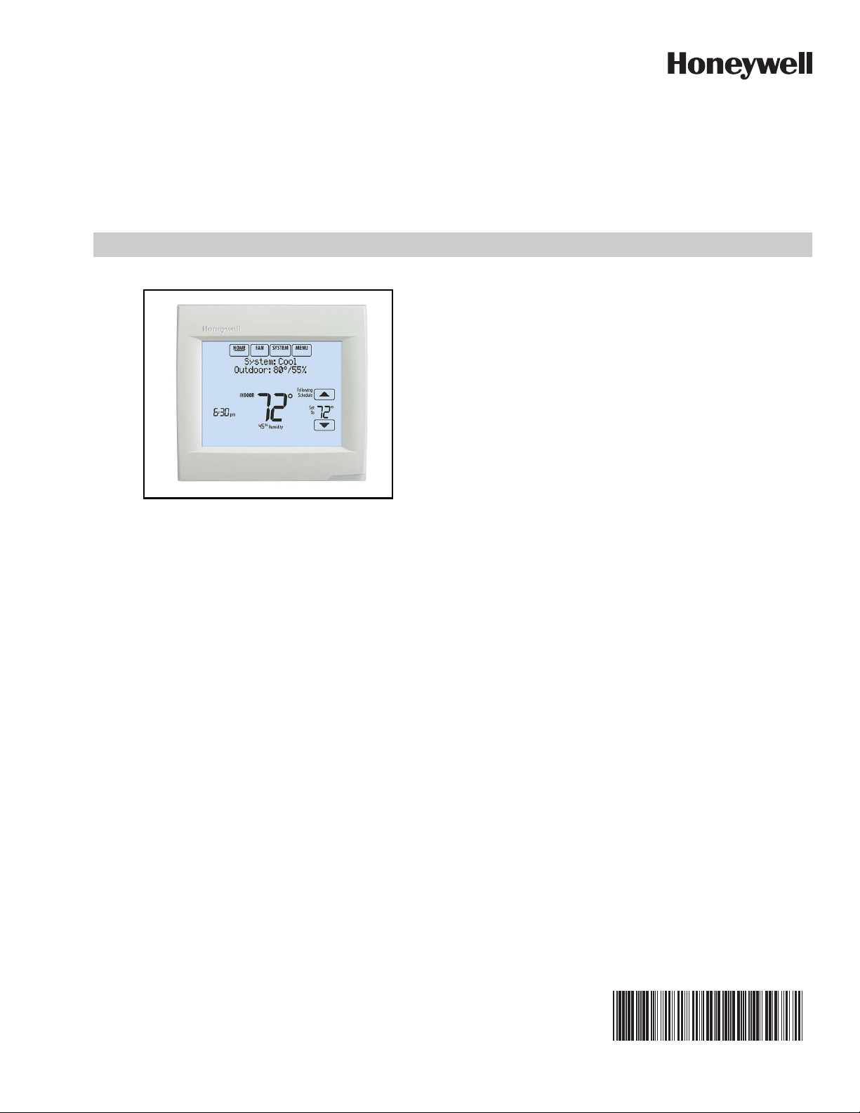
The VisionPRO® 8000 with Wi-Fi features an effortless, 7-Day
programmable touchscreen thermostat that provides control
of temperature and one of the following: humidification,
dehumidification, or ventilation. Up to 3 Heat/2 Cool heat
pump systems or up to 2 Heat/2 Cool conventional systems
are supported in residential and commercial applications.
• Customizable Service Reminders
Set up to 10 service reminders. Choose from the pre-set
options or customize your own. Reminders can be based
on date or the outdoor temperature.
• Selectable for Residential and Light Commercial
Applications
One thermostat does it all to meet the needs of Residential
and Light Commercial applications. Simply select Residential or Commercial during the installer setup. If Commercial
is selected, the thermostat will use commercial language,
meet building codes and offer 365 day holiday scheduling.

VISIONPRO® 8000 WITH WI-FI
CONTENTS
®
Application ............................................... 1
Ordering Information ............................... 2
Specifications .......................................... 3
System Installation .................................. 5
When Installing this Product... ......................... 5
Wiring 24 Vac Common .................................... 6
Selecting Discharge Air Temperature Sensor
Mounting Locations .......................................... 6
Selecting Discharge Air Temperature Sensor Mounting
Locations .................................................................. 6
Selecting Thermostat Location ........................ 8
Installing Wallplate ............................................ 8
Make Changes to Installer Setup ..................... 10
Installer Setup (ISU) Table. ..................... 11
Connect to Wi-Fi® Network .................... 37
Installer Tests .......................................... 39
Using the Installer Test ..................................... 39
Operation ................................................. 40
Setting the Time/Date ....................................... 41
Setting the Fan .................................................. 41
Setting System Mode ........................................ 42
Preset Energy-Saving Schedules ............................. 42
Advanced Features ........................................... 52
Adaptive Intelligent Recovery (residential use only) . 52
Compressor Protection ............................................. 52
Staging Control ................................................. 53
Heat Pump and Backup Heat Operation 56
Geothermal Radiant Heat ................................. 56
Indoor Air Quality (IAQ) Control ............. 58
Humidification ................................................... 58
Set up Humidification ................................................ 58
Control Humidification Level ..................................... 60
Dehumidification - Residential ......................... 60
Set up Dehumidification With Cooling System .......... 61
Set up Dehumidification With Whole House Dehumidifier 61
Set up Dehumidification Away Mode ........................ 63
Control Dehumidification Level ................................. 64
Dehumidification - Commercial ....................... 64
Set up Dehumidification With Cooling System .......... 65
Set up Dehumidification With Dehumidifier ............... 66
Control Dehumidification Level ................................. 67
Ventilation .......................................................... 68
Set up Ventilation ...................................................... 69
IAQ Reminders ......................................... 73
Customizable Reminders ....................... 73
Commercial Features .............................. 78
Ramp Rates (Commercial Use) ........................ 81
Economizer and Time of Day (TOD) Operation 81
Pre-Occupancy Purge ....................................... 82
Wired Indoor Sensors ............................. 82
Wiring ....................................................... 84
Wiring IAQ Equipment or a Heat/Cool Stage to the
Universal Terminals .......................................... 86
Wiring C7089U1006 Outdoor Sensor .............. 87
Wiring guide — Wired Indoor Sensors ............ 88
Troubleshooting ...................................... 89
Regulatory Information ........................... 90
ORDERING INFORMATION
When purchasing replacement and modernization products from your TRADELINE® wholesaler or distributor, refer to the
TRADELINE® Catalog or price sheets for complete ordering number. If you have additional questions, need further information,
or would like to comment on our products or services, please write or phone:
1. Your local Honeywell Environmental and Combustion Controls Sales Office (check white pages of your phone directory).
2. Honeywell Customer Care
1985 Douglas Drive North
Minneapolis, Minnesota 55422-4386
3. http://customer.honeywell.com or http://customer.honeywell.ca
International Sales and Service Offices in all principal cities of the world. Manufacturing in Belgium, Canada, China, Czech
Republic, Germany, Hungary, Italy, Mexico, Netherlands, United Kingdom, and United States.
33-00096—01 2
VISIONPRO® 8000 WITH WI-FI
M34521
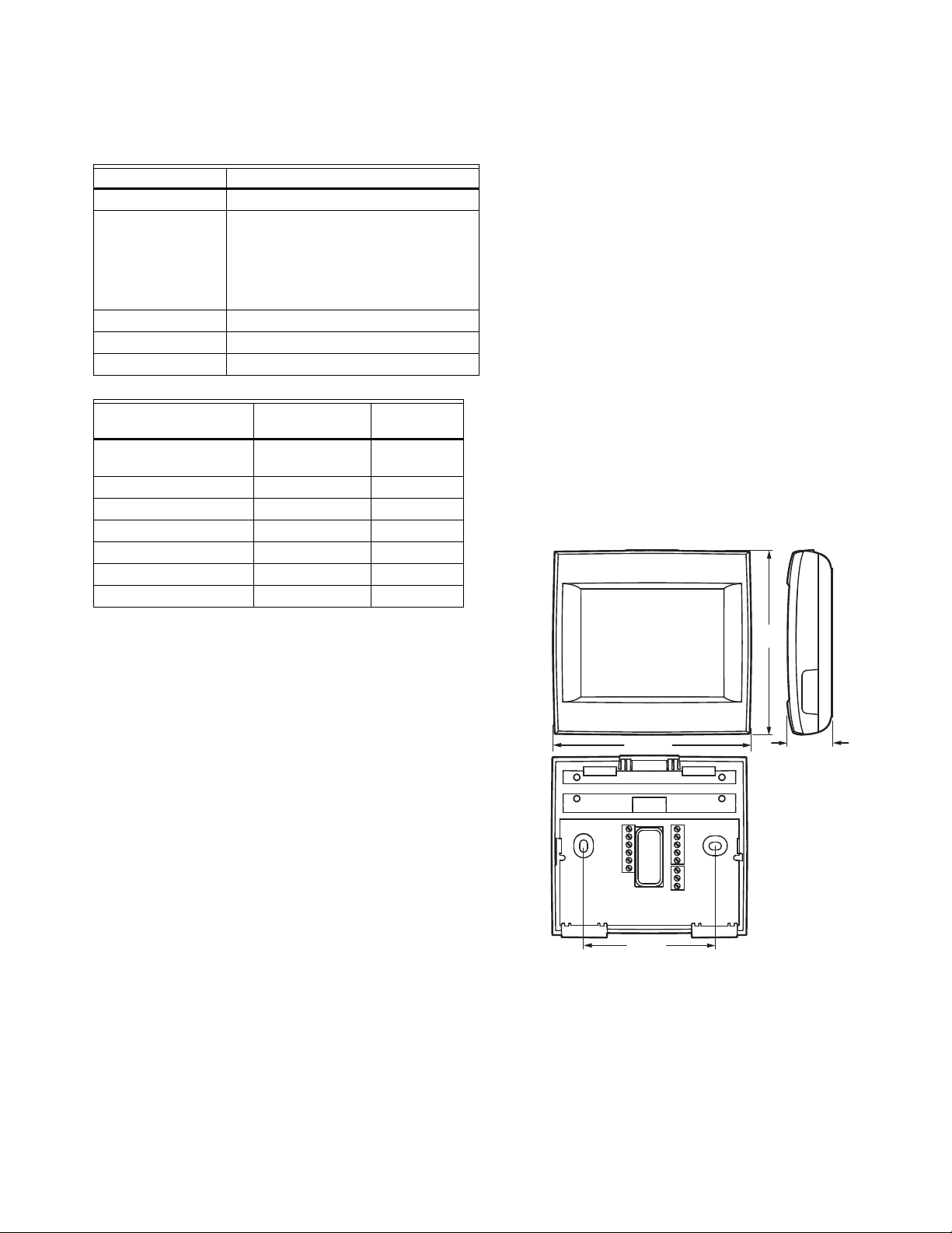
4-15/16 (126)
4-5/8
(118)
1-1/8 (29)
3-5/16 (84)
®
SPECIFICATIONS
Thermostat Description:
Feature Description
Powering method • Common wire
System types (up to
3 heat/2 cool heat
pump and up to
2 heat/2 cool
conventional)
Changeover Manual or Auto changeover selectable
System setting Em Heat-Heat-Off-Cool-Auto
Fan setting Auto-On-Circ-Follow Schedule
Ter minal
W - O/B 18 to 30 VAC and
Y (cooling) 18 to 30 VAC 1.00A
G (fan) 18 to 30 VAC 0.50A
W2 - Aux 1 (heating) 18 to 30 VAC 0.60A
Y2 (cooling) 18 to 30 VAC 0.60A
A-L/A (Output) 18 to 30 VAC 1.00A
U1, U1, S1, S1 30 VAC max. 0.50A
Power Consumption of TH8321:
Backlight on: 1.48 VA
Backlight off: 0.88 VA
Temperature Setting Range:
Heating: 40 to 90 °F (4.5 to 32 °C).
Cooling: 50 to 99 °F (10 to 37 °C).
• Gas, oil or electric heat with air
conditioning
• Warm air, hot water, high-efficiency
furnaces, heat pumps, steam and
gravity
• Cool only
Voltag e
(50/60 Hz)
Max. Current
Rating
1.00A
750 mVDC
Cool Indication:
VisionPRO® 8000 with Wi-Fi
® displays “Cool On” when the
thermostat turns the cooling on.
Heat Indication:
VisionPRO® 8000 with Wi-Fi displays “Heat On” when the
thermostat turns the heating on.
Auxiliary Heat Indication:
VisionPRO® 8000 with Wi-Fi displays “Aux Heat On” when the
thermostat turns the auxiliary heat on.
Interstage Differential:
Comfort:
The thermostat keeps the indoor temperature within 1
degree of the setpoint (droop less control). The thermostat
turns on stage 2 when the capacity on stage 1 reaches 90%.
When the interstage differential is set to 1.0 or higher, the ther-
mostat stages the equipment based on how far the indoor
temperature is from the setpoint (ISU 303 to 309). See
page 16 for more information.
Clock Accuracy: 1 minute per month at 77 °F (25 °C). ± 2
minutes per month over the operating ambient temperature
range.
Mounting Means:
Thermostat mounts directly on the wall in the living space
using mounting screws and anchors provided. Fits a horizontal 2 x 4 in. junction box.
Temperature Sensor Accuracy:
± 1.5 F at 70 F (0.75 C at 21.0 C)
Humidification Setting Range:
10% to 60% RH.
Dehumidification Setting Range:
40% to 80% RH.
Humidity Display Range:
0% to 99%.
Humidity Sensor Accuracy:
± 5% RH from 30% to 50% RH at 75 F.
Fig. 1. Dimensions of thermostat in in. (mm).
3 33-00096—01
VISIONPRO® 8000 WITH WI-FI
®
Accessories
Product Part Number
Wired Outdoor Sensor 10k ohm NTC C7089U1006
Wired Wall-mount Indoor Sensor 10k ohm NTC C7189U1005
Wired Flush-mount Indoor Sensor 20k ohm NTC C7772A1004, C7772A1012
Wired Wall-mount Indoor Sensor 20k ohm NTC TR21
Wired Wall-mount Indoor Sensor 10k ohm NTC TR21-A
Cover Plate (covers marks left by old thermostats) THP2400A1019
Wire Saver Module THP9045A1023
Discharge Air Temperature Sensor C7735
33-00096—01 4
SYSTEM INSTALLATION
1-855-733-5465
yourhome.honeywell.com
Honeywell
Golden Valley, MN 55422
RoHs Compliant
Conformité RoHs
Assembled in Mexico
Assemblé au Mexique
TH8321WF1001
1
1524
M35343A
Password
(Date Code)
When Installing this Product...
1. Read these instructions carefully. Failure to follow the
instructions can damage the product or cause a hazardous condition.
2. Check the ratings given in the instructions to make sure
the product is suitable for your application.
3. Installer must be a trained, experienced service
technician.
4. After completing installation, use these instructions to
verify the product operation.
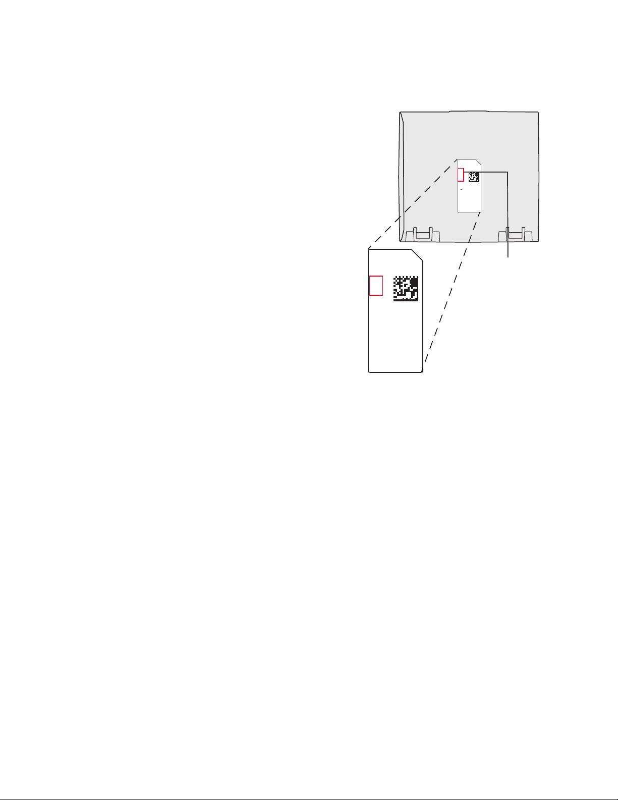
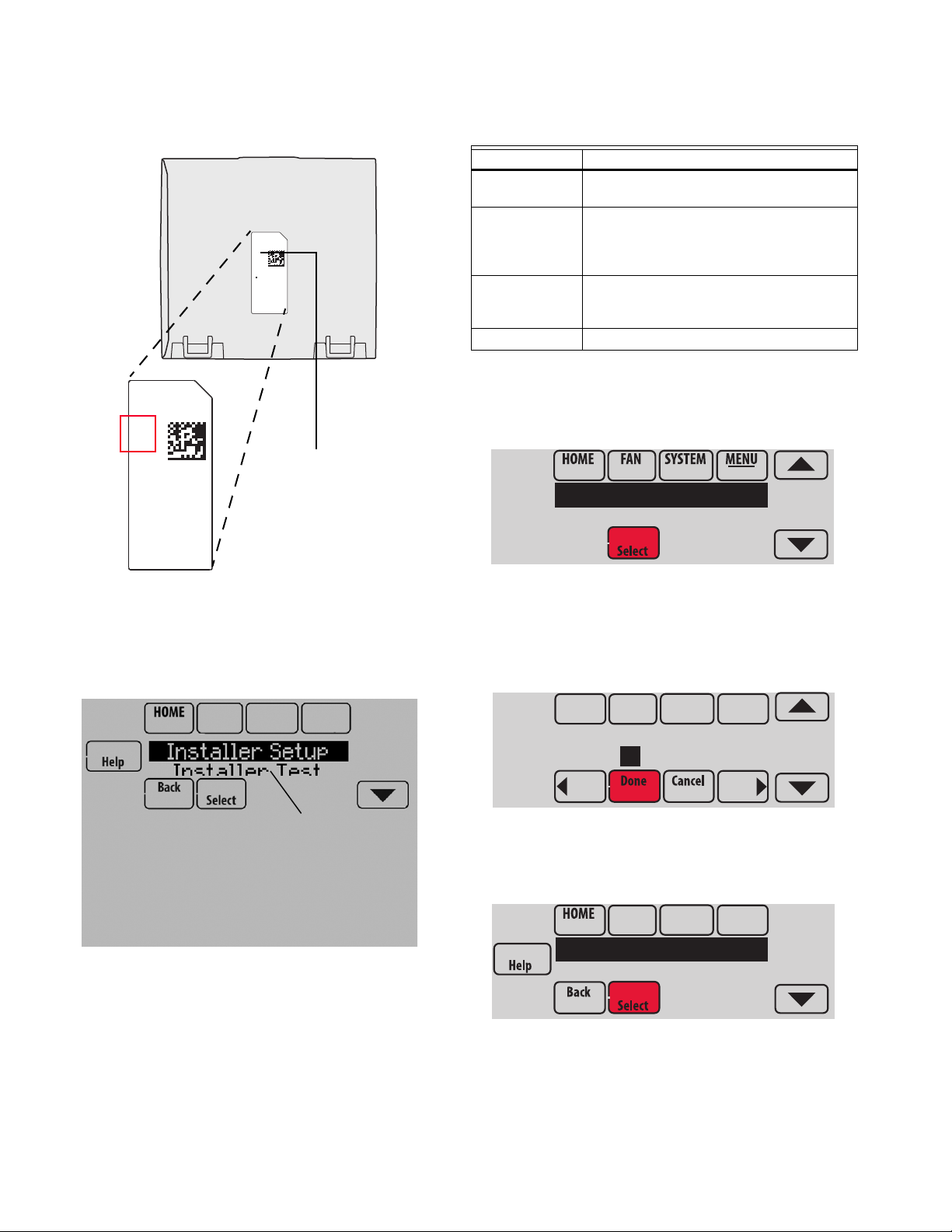
Finding Your Password (Date Code)
You will need the thermostat password to:
• Make changes to Installer Setup
• Perform an Installer Test
• Reset Thermostat to Factory Default Settings
The password (date code) is located on the back of the
thermostat (see Fig. 2)
VISIONPRO® 8000 WITH WI-FI
RoHs Compliant
Conformité RoHs
Assembled in Mexico
Assemblé au Mexique
1524
1
TH8321WF1001
Residential/Résidentiel
1-800-468-1502
http://yourhome.honeywell.com
Commercial/Commerciale
1-888-245-1051
http://customer.honeywell.com
Honeywell, Golden Valley, MN 55422
M35344
®
Fig. 2. Finding thermostat password.
You can also find the password (date code) by pressing MENU,
selecting Dealer Information and then scrolling down to see the
Date Code.
5 33-00096—01
VISIONPRO® 8000 WITH WI-FI
MOUNT DISCHARGE
SENSOR HERE
M35768
HEAT
EXCHANGER
BLOWER
VENTILATOR
OR
DEHUMIDIFIER
A-COIL
®
INSTALLATION
Model Numbering TH8321
Stages 3H/2C HP
2H/2C CONV
Residential or Commercial
Powered - C Wire (wire saver compatible)
Onboard Humidity Sensor
Number of Universal Relays 1
Number of Universal Sensor Inputs 1
Economizer / TOD Output
Wiring 24 Vac Common
• Single-Transformer System—Connect the common side of
the transformer to the C screw terminal of the thermostat.
Leave the metal jumper wires in place between R and RC.
• Two-Transformer System—Connect the common side of the
cooling transformer to the C screw terminal of the
thermostat. Remove the metal jumper wire between R and
RC. Connect the hot side of heating transformer to R and
connect the hot side of cooling transformer to RC.
Selecting Discharge Air Temperature
Sensor Mounting Locations
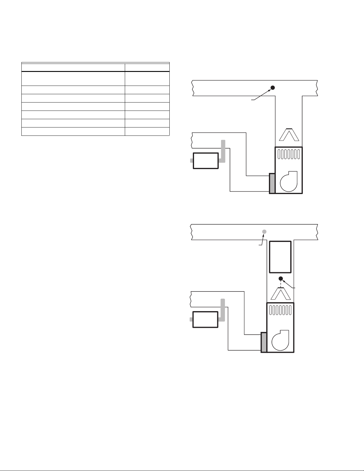
Refer to the guidelines below and Fig. 3–7 for mounting
locations of the Discharge Air Temperature Sensor.
Selecting Discharge Air Temperature
Sensor Mounting Location
1. Mount the Discharge Air Temperature Sensor on the
supply duct in a location where the air is mixed well.
Mount the Discharge Air Temperature Sensor out of sight
of the A-Coil/Heat Exchanger when possible. See Fig. 3.
2. When possible, mount the Discharge Air Temperature
Sensor upstream of a Steam Humidifier, a Fan Powered
Humidifier or a Dehumidifier that is ducted to the supply.
See Fig. 4–5.
3. If space does not allow a Discharge Air Temperature
Sensor upstream of a Steam Humidifier or Fan Powered
Humidifier, mount the Discharge Air Temperature Sensor
downstream of the Humidifier. See Fig. 4.
4. If a Bypass Humidifier is installed, mount the Discharge
Air Temperature Sensor downstream of the Bypass
Humidifier. See Fig. 6–7.
Selecting Discharge Air Temperature
Sensor Mounting Location
1. Install the Discharge Air Temperature Sensor on the duct
in a location where the air is mixed well. See Fig. 3–7.
Fig. 3.
ALTERNATE MOUNTING LOCATION
FOR DISCHAR GE SENSO R.
HUMIDIFIER
MOUNT
DISCHARGE
SENSOR HERE
ABOVE
CENTER
VENTILATOR
OR
DEHUMIDIFIER
HEAT
EXCHANGER
BLOWER
OF A-COIL
UPSTREAM OF
HUMIDIFIER
M35769
33-00096—01 6
Fig. 4.
VISIONPRO® 8000 WITH WI-FI
M35770
HEAT
EXCHANGER
BLOWER
ALTERNATE MOUNTING LOCATION
FOR DISCHARGE SENSOR.
MOUNT
DISCHARGE
SENSOR HERE
ABOVE CENTER
OF A-COIL
UPSTREAM OF
DEHUMIDIFIER
DEHUMIDIFIER
HEAT
EXCHANGER
BLOWER
VENTILATOR
OR
DEHUMIDIFIER
MOUNT
DISCHARGE
SENSOR HERE
BYPASS
HUMIDIFIER
M35771
HEAT
EXCHANGER
BLOWER
VENTILATOR
OR
DEHUMIDIF IER
MOUNT
DISCHARGE
SENSOR HERE
BYPASS
HUMIDIFIER
M35772
M32995
Fig. 7.
®
Fig. 5.
Fig. 6.
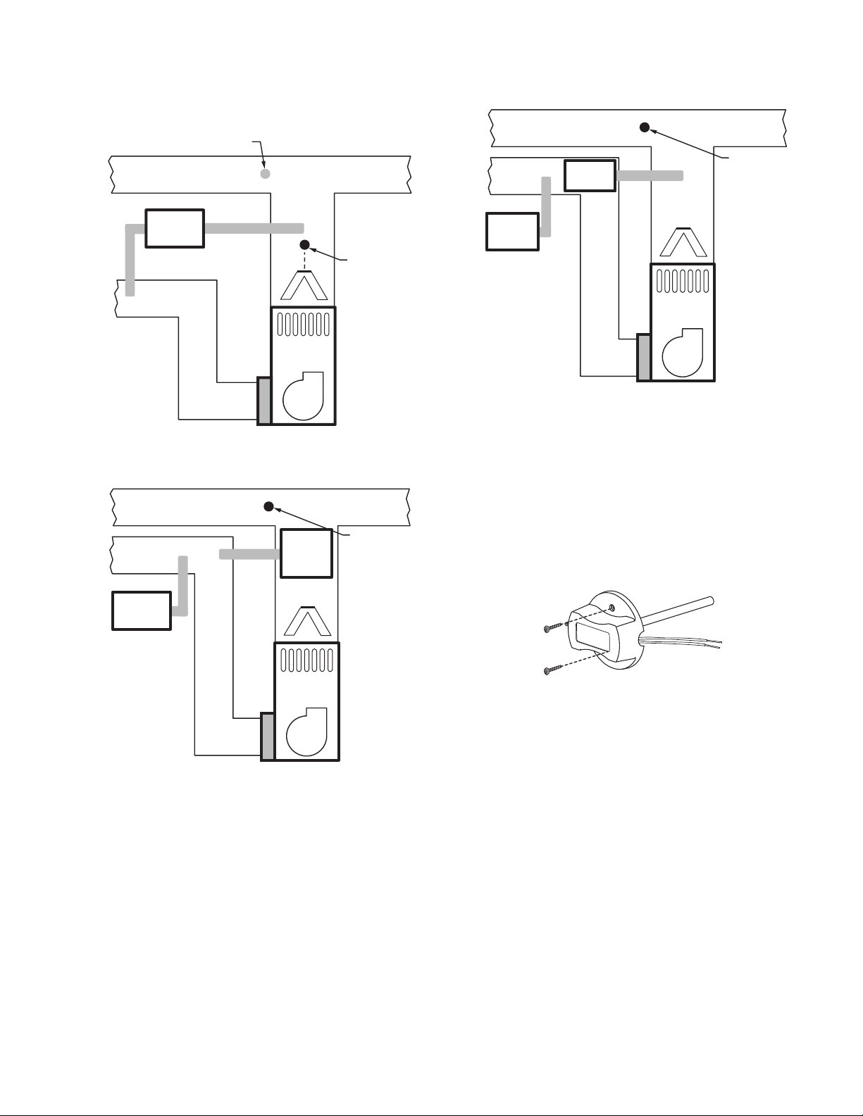
Installing Discharge Air Temperature
Sensor
Use the following steps to mount the Discharge Sensor:
1. Attach plastic cover to the sensor probe.
2. Drill 1/4-inch hole for the sensor probe and mount it to
the ductwork with enclosed screws (see Fig. 8).
3. Connect wires to S1 terminal at the thermostat.
4. Setup the S1 terminal in the Installer Setup at the ther-
mostat.
Fig. 8. Mounting Discharge Air Sensor.
7 33-00096—01
VISIONPRO® 8000 WITH WI-FI
CAUTION
5 FEET
[1.5 METERS]
YES
NO
NO
NO
M19925
®
Selecting Thermostat Location
Install the thermostat about 5 ft. (1.5m) above the floor in an area
with good air circulation at average temperature. See Fig. 9.
Fig. 9. Selecting thermostat location.
Do not install the thermostat where it can be affected by:
— Drafts or dead spots behind doors and in corners.
— Hot or cold air from ducts.
— Radiant heat from sun or appliances.
— Concealed pipes and chimneys.
— Unheated (uncooled) areas such as an outside wall behind
the thermostat.
Installing Wallplate
Electrical Hazard.
Can cause electrical shock or equipment damage.
Disconnect power before wiring.
The thermostat can be mounted horizontally on the wall or on a
4 in. x 2 in. (101.6 mm x 50.8 mm) wiring box.
2. Position and level the wallplate (for appearance only).
3. Use a pencil to mark the mounting holes.
4. Remove the wallplate from the wall and, if drywall, drill
two 3/16-in. holes in the wall, as marked. For firmer
material such as plaster, drill two 7/32-in. holes. Gently
tap anchors (provided) into the drilled holes until flush
with the wall.
5. Position the wallplate over the holes, pulling wires
through the wiring opening. See Fig. 11.
6. Insert the mounting screws into the holes and tighten.
C
S1
K
R
C
R
U1
U1
U2
U2
S1
S1
S1
W
O/B
Y
Y
G
G
AUX
W2
-E
Y2
Y2
L/A
A
Fig. 11. Mounting wallplate.
7. Connect common side of transformer to C terminal.
CONVENTIONAL
C
K
RC
R
U1
U1
U2
U2
W2
S1
S1
W
Y
G
Y2
A
S1
S1
O/B
Y
G
AUX
-E
Y2
L/A
1. Press button on top and pull to remove the wallplate.
33-00096—01 8
Fig. 10. Separate wallplate from thermostat.
HEAT PUMP
Fig. 12. Connecting C wire to terminal block.
Wiring the Thermostat
1. Refer to Fig. 13. See Table 9 on page 84 for terminal
designations and “Wiring” beginning on page 84 for more
information.
2. Turn on 24 VAC NOW.
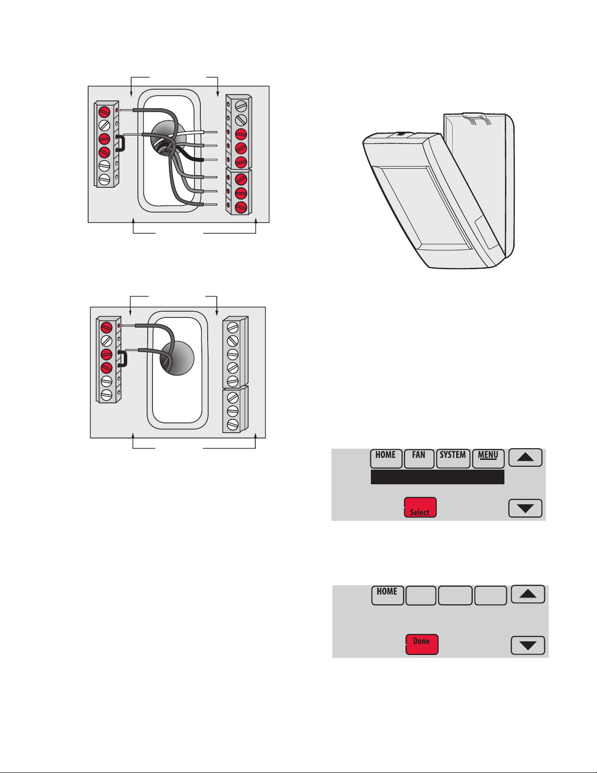
Fig. 13. Thermostat wired directly to equipment.
S1
S1
W
Y
G
W2
Y2
A
S1
S1
O/B
Y
G
AUX
-E
Y2
L/A
K
RC
R
U1
U1
U2
U2
C
CONVENTIONAL
HEAT PUMP
MCR34022
Dealer Information
Installer Options
MCR35348
TH8321WF1001
Date Code: 1524
1. Power the thermostat using Rc and C terminals. Refer to
Fig. 14.
CONVENTIONAL
VISIONPRO® 8000 WITH WI-FI
Mounting Thermostat on Wallplate
1. Align thermostat at bottom and snap into place as
shown.
Fig. 15. Mount thermostat.
®
C
K
RC
R
U1
U1
U2
U2
HEAT PUMP
W2
S1
S1
W
Y
G
Y2
A
S1
S1
O/B
Y
G
AUX
-E
Y2
L/A
Fig. 14. Inserting wires in thermostat terminal block.
Finding Your Password (Date Code)
to Access Installer Options
You need a password (Date Code) to access Installer Options.
Installer Options allow you to:
• Make changes to the Installer Setup.
• Perform an Installer Test.
• Reset the thermostat to Factory Default settings.
The password (Date Code) is located on the back of the
thermostat. It can also be found by following these steps:
1. Touch Menu.
2. Select Dealer Information.
Fig. 16.
3. Scroll down to see the Date Code.
Fig. 17.
9 33-00096—01
VISIONPRO® 8000 WITH WI-FI
Residential/Résidentiel
1-800-468-1502
http://yourhome.honeywell.com
Commercial/Commerciale
1-888-245-1051
http://customer.honeywell.com
Honeywell, Golden Valley, MN 55422
RoHs Compliant
Conformité RoHs
Assembled in Mexico
Assemblé au Mexique
TH8321WF1001
1
1524
M35344
Password
(Date Code)
Scroll to see:
Installer Setup
Installer Test
Reset To Defaults
Device Info
MCR33976
Installer Options
MCR33977
Enter password
0 0 0 0
MCR34015
Installer Setup
Installer Test
®
Thermostat Password (Date Code)
Table 1. Installer Options.
Menu Item Description
Installer Setup Select INSTALLER SETUP to set system
settings one by one.
Installer Test Select INSTALLER TEST to quickly
determine if the heat, cool, fan and
thermostat are operating properly. Minimum
off timers are ignored during the test.
Reset To
Defaults
Select RESET TO DEFAULTS to place all
thermostat settings back to the factory
settings.
Device Info For Honeywell use only.
RoHs Compliant
Conformité RoHs
Assembled in Mexico
Assemblé au Mexique
M35343A
1524
1
TH8321WF1001
1-855-733-5465
yourhome.honeywell.com
Honeywell
Golden Valley, MN 55422
Fig. 18. Locate password.
The following options are available when you access Installer
Options. For more information on each, press Help on the
thermostat or see Table 1.
Make Changes to Installer Setup
1. Touch Menu.
2. Select Installer Options.
Fig. 20.
3. Enter password (date code) and touch Done. See “Find-
ing Your Password (Date Code) to Access Installer
Options” beginning on page 9 for more information.
Fig. 19.
33-00096—01 10
Fig. 21.
4. Select Installer Setup.
Fig. 22.
5. Follow prompts on the screen to select the desired setup
options. See Table 2 for Installer Setup options.
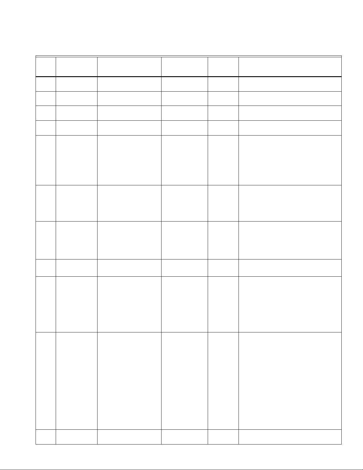
ISU
Number
Installer Setup
Name Settings Default
101 Application
103 Thermostat Name
104 Thermostat Type
105 Temperature Scale
106 Outdoor Temp
200 Heating System
201 Heating
Equipment
202 Radiant Heat
Stages
203 Radiant Stage 1
Residential
Commercial
[Select Thermostat Name]
Non-Programmable
Programmable
Fahrenheit
Celsius
Wired/Internet
No
Conv. Forced Air
Heat Pump
Radiant Heat
Other
None (Cool Only)
Heat Pump:
Air to Air Heat Pump
Geothermal
Geothermal Radiant
0
1
2
None
U1
Table 2. Installer Setup (ISU) Table.
Residential,
Commercial
or Both Notes
Residential Both
Thermostat Both The Web Interface displays the name of the
Programmable Both
Fahrenheit Both
No Both Select Wired/Internet to indicate that you are
Conv. Forced Air Both For Dual Fuel, choose Heat Pump.
Air to Air Heat Pump Both This ISU is not displayed when ISU 200 Heating
Both Select the number of radiant heat stages.
Default varies based
Both This ISU is only displayed when ISU 201
on previous
selections
VISIONPRO® 8000 WITH WI-FI
thermostat that you enter on this screen.
going to connect a wired outdoor sensor or
connect to the internet. This will allow you to
configure settings prior to the Internet being
connected.
Select No if you are not going to connect to an
outdoor sensor or the Internet.
System is set to Conv. Forced Air, Radiant
Heat, Other or None (Cool Only).
See “Geothermal Radiant Heat” beginning on
page 56.
Heating Equipment is Geothermal Radiant.
Geothermal Radiant Heat must be wired to
universal terminal U1.
®
205 Geo Forced Air
206 Reversing Valve
None
Cooling Only
Heating and Cooling
O (O/B on Cool)
B (O/B on Heat)
U1 is a normally open set of dry contacts. U1
requires power from the system transformer or
a separate transformer.
Heating and Cooling Both This thermostat has the capability of controlling
Geothermal Radiant Heat, Geothermal Forced
Air and Backup Heat.
If this thermostat is not controlling the
Geothermal Forced Air System, select None.
This setting is typically used if the thermostat is
only controlling Geothermal Radiant Heat.
If this thermostat is using the Geothermal
Forced Air System for cooling and not for
heating, select Cooling Only.
If this thermostat is using the Geothermal
Forced Air System for both heating and cooling,
select Heating and Cooling.
O/B on Cool Both Only displayed if the equipment type is Air to Air
Heat Pump, Geothermal or Geothermal Radiant.
11 33-00096—01

VISIONPRO® 8000 WITH WI-FI
®
Table 2. Installer Setup (ISU) Table. (Continued)
ISU
Number
Installer Setup
Name Settings Default
207 Cool Stages /
Compressor
Stages
202,
207
Heat / Radiant /
Backup Heat
Stages
208 Cool Stage 3
0
1
2
3
1 - 3
None
U1
1 if ISU 101 is
Residential
2 if ISU 101 is
Commercial
Default is 1 stage if
ISU 101 Application
is Residential
Default is 2 stages if
ISU 101 Application
is Commercial
Default varies based
on previous
selections
Residential,
Commercial
or Both Notes
Both Conventional:
Cool Stage 3 is only available if ISU 101 is
Commercial.
Cool Stage 3 must be wired to the universal
terminal (U1).
Heat Pumps:
Maximum of 2 Compressor Stages for heat
pump systems.
Both Maximum of 3 stages for conventional systems.
Maximum of 3 stages for radiant heat.
Maximum of 3 stages for Primary Heat.
(Heating system, ISU 200 is set to “Other.”)
Maximum of 2 Backup Heat Stages for systems
with more than 1 heating equipment type.
NOTE: Depending on the application, the text
displayed on the screen may show
the specific heating equipment type.
Commercial Cool Stage 3 is only available if ISU 101 is
Commercial.
Cool Stage 3 must be wired to the universal
terminal (U1).
210 Heat Stage 3
211 Fan Control in
Heat
212 Backup Heat Type
213 Backup Heat
Stages
None
U1
No Fan
Equip Controls Fan
Tstat Controls Fan
None
Electric
Gas/Oil
0 - 2
U1 are normally open dry contacts when
configured for a stage of Cool. U1 requires
power from a system transformer or a separate
transformer.
Default varies based
on previous
Both Heat Stage 3 must be wired to the universal
terminal (U1).
selections
U1 is a normally open dry contact when
configured for a stage of Heat. U1 requires
power from a system transformer or a separate
transformer.
Equip Controls Fan Both No Fan is only displayed when ISU 201 Heating
Equipment is Other.
None Both This ISU is only displayed when ISU 200
Heating Equipment is Radiant Heat or Other.
When ISU 200 Heating Equipment is Radiant
Heat, the thermostat keeps the Radiant Heat on
when it calls for Backup Heat.
When ISU 200 Heating Equipment is Other, you
can select how the backup operates. See ISU
215.
1 Both This ISU is only displayed when a backup heat
source is selected at ISU 212 Backup Heat Type.
Maximum of 2 Backup Heat stages.
33-00096—01 12

Table 2. Installer Setup (ISU) Table. (Continued)
VISIONPRO® 8000 WITH WI-FI
®
ISU
Number
Installer Setup
Name Settings Default
214 Backup Heat Stg 2
215 Run Backup Heat
with Primary
216 Backup Heat Fan
None
U1
No
Yes
Equip Controls Fan
Tstat Controls Fan
Residential,
Commercial
or Both Notes
Default varies based
on previous
selections
Both The thermostat supports up to 2 backup heat
stages. When there are 2 backup heat stages,
backup heat stage #2 must be wired to U1.
U1 is a normally open dry contact when
configured for a stage of Heat. U1 requires
power from a system transformer or a separate
transformer.
No Both This ISU is only displayed when ISU 200
Heating Equipment is Other.
When ISU 200 Heating Equipment is Other, you
can select how the Backup Heat operates. The
thermostat can be setup to keep the primary
heat source on when it calls for Backup Heat or
the thermostat can be setup to turn off the
primary heat source when it calls for Backup
Heat.
When ISU 200 Heating Equipment is Radiant
Heat, the thermostat keeps the Radiant Heat on
when it calls for Backup Heat.
Tstat Controls Fan Both This ISU is only displayed for conventional
systems when ISU 212 Backup Heat Type is
Electric.
217 Backup Heat
Stage 2
218 Backup Heat Type
219 External Fossil
Fuel Kit
None
U1
Electric
Gas/Oil
No
Yes
Backup Heat Fan Operation automatically
defaults to Equip Controls Fan when ISU 212
Backup Heat Type is Gas/Oil.
Default varies based
on previous
selections
Both The thermostat can support up to 2 backup heat
stages for heat pump applications. When there
are 2 backup heat stages, backup heat stage 2
must be wired to U1.
U1 is a normally open dry contact when
configured for a stage of Heat. U1 requires
power from a system transformer or a separate
transformer.
Electric Both This ISU is only displayed when ISU 201
Heating Equipment is Air to Air Heat Pump,
Geothermal or Geothermal Radiant and there
is at least one stage of backup heat.
See “Heat Pump and Backup Heat Operation”
beginning on page 56.
No Both This ISU is only displayed when ISU 201
Heating Equipment is Air to Air Heat Pump,
Geothermal or Geothermal Radiant and ISU
218 Backup Heat Type is Gas/Oil.
13 33-00096—01

VISIONPRO® 8000 WITH WI-FI
®
Table 2. Installer Setup (ISU) Table. (Continued)
ISU
Number
Installer Setup
Name Settings Default
222 A-L/A Terminal
None
Time Of Day
Economizer
Heat Pump Fault
Residential,
Commercial
or Both Notes
None Commercial This ISU is only displayed when ISU 101
Application is Commercial.
Note: When the thermostat is setup for
Residential, the L/A terminal operates as
described under "Heat Pump Fault". The L/A
terminal requires no setup for residential
applications.
None: The A-L/A terminal is not used.
Time of Day: The A-L/A terminal is energized
during Occupied periods and when the user
overrides the temperature. The terminal is deenergized during Unoccupied periods and in
Standby mode.
Economizer: The thermostat controls an
economizer module to provide ventilation
during Occupied periods and free cooling when
outdoor conditions are favorable. The
A-L/A terminal is energized during Occupied
periods and during a call for cooling in
Unoccupied periods. See “Economizer and Time
of Day (TOD) Operation” beginning on page 81.
Notes: The economizer module determines
when outdoor conditions are favorable for free
cooling.
300 System
Changeover
Manual
Automatic
Manual:
if ISU 101 is
Residential
Automatic:
if ISU 101 is
Commercial
Heat Pump Fault: When 24 volts is detected on
the L/A terminal (compressor monitor), the
thermostat displays a message to alert the user
when the heat pump requires service. The L/A
terminal sends a continuous output to a zone
panel when the thermostat is set to Emergency
Heat mode. The zone panel will not turn on the
heat pump when a zone is set to Emergency
Heat mode.
Both Manual: The user must select heating or
cooling as needed to maintain the desired
indoor temperature.
Automatic: The user has the option to select
Auto for the system setting. In Auto mode, the
thermostat controls heating and cooling
equipment as needed to maintain the desired
indoor temperature.
33-00096—01 14

Table 2. Installer Setup (ISU) Table. (Continued)
VISIONPRO® 8000 WITH WI-FI
®
ISU
Number
Installer Setup
Name Settings Default
300 Auto Changeover
Deadband
301 Control Options
2° F to 9° F (in 1° F increments)
Basic Options
Advanced Options
Residential,
Commercial
or Both Notes
3° F Both This ISU is only displayed when ISU 300 is set
to Automatic.
Deadband is the minimum separation between
heat and cool settings when the thermostat is
setup for Auto Changeover. For example, if the
deadband is set to 3° F and the cool setpoint is
75° F, the warmest heat setpoint allowed would
be 72° F. If the heat setpoint is adjusted above
72° F, it will automatically adjust the cooling
setpoint higher to maintain the 3° F deadband.
When ISU 907 or ISU 910 (Dehum Over Cooling
Limit) is set to 1, 2, 3, 4 or 5 F, the thermostat
will not show the full Deadband range. For
example, if you set a Deadband of 3 F and an
Over Cooling Limit of 2 F, the minimum
Deadband that you can select will be 5 F. This
prevents the heating system from turning on
when the thermostat over cools to reach the
dehumidification setting.
Basic Options Both Basic Options: The Installer Setup displays
basic temperature control options which include
Backup Heat Droop, Backup Heat Upstage
Timer, Outdoor Temperature Lockouts and
Cycle Rate settings per stage.
302 Finish With High
Cool Stage
302 Finish With High
Heat Stage
No
Yes
No
Yes
Note: Outdoor Temperature Lockouts only apply
to Heat Pump applications.
Advanced Options: The Installer Setup displays
both Basic and Advanced Options. Advanced
temperature control options include Finish With
High Cool Stage, Finish With High Heat Stage,
and Temperature Differential settings between
all stages.
No Both ISU 301 Control Options must be set to
Advanced to view or adjust Finish With High
Cool Stage.
This ISU is only displayed when the thermostat
is set for 2 or more cool stages.
When set to Yes, this feature keeps the high
stage of the cooling equipment running until the
desired setpoint is reached.
No Both ISU 301 Control Options must be set to
Advanced to view or adjust Finish With High
Heat Stage.
This ISU is only displayed when the thermostat
is set for 2 or more heat stages.
When set to Yes, this feature keeps the high
stage of the heating equipment running until the
desired setpoint is reached.
15 33-00096—01

VISIONPRO® 8000 WITH WI-FI
®
Table 2. Installer Setup (ISU) Table. (Continued)
ISU
Number
Installer Setup
Name Settings Default
303 Cool Differential
Stage 2
303 Cool Differential
Stage 3
305 Heat Differential
Stage 2
Note: Depending
on the application,
the text displayed
on the screen may
show the specific
heating equipment
type
Comfort
1.0° F to 3.5° F from setpoint (in
0.5° F increments)
Comfort
1.0°F - 4.0°F from setpoint (in
0.5° F increments)
Comfort
1.0° F to 3.5° F from setpoint (in
0.5° F increments)
Residential,
Commercial
or Both Notes
Comfort Both ISU 301 Control Options must be set to
Advanced to view or adjust this ISU.
This ISU is only displayed when the thermostat
is set to 2 cool stages.
The indoor temperature must rise to the
selected differential setting before the
thermostat turns on the stage of cooling. For
example, if stage 2 is set to 2° F (1.0° C), the
indoor temperature must be 2° F (1.0° C) away
from the setpoint before stage 2 turns on. When
set to Comfort, the thermostat uses the stage of
cooling as needed to keep the indoor
temperature within 1° F (0.5° C) degree of the
setpoint.
Comfort Commercial ISU 301 Control Options must be set to
Advanced to view or adjust this ISU.
This ISU is only displayed when the thermostat
is set to 3 cool stages.
The indoor temperature must rise to the
selected differential setting before the
thermostat turns on the stage of cooling. For
example, if stage 3 is set to 2° F (1.0° C), the
indoor temperature must be 2° F (1.0° C) away
from the setpoint before stage 3 turns on. When
set to Comfort, the thermostat uses the stage of
cooling as needed to keep the indoor
temperature within 1° F (0.5° C) degree of the
setpoint.
Comfort Both ISU 301 Control Options must be set to
Advanced to view or adjust this ISU.
This ISU is only displayed for conventional
systems that have 2 heat stages.
The indoor temperature must drop to the
selected differential setting before the
thermostat will turn on the stage of heating. For
example, if stage 2 is set to 2° F (1.0° C), the
indoor temperature must be 2° F (1.0° C) away
from the setpoint before stage 2 turns on. When
set to Comfort, the thermostat will use the stage
of heating as needed to keep the indoor
temperature within 1° F (0.5° C) degree of the
setpoint.
33-00096—01 16

Table 2. Installer Setup (ISU) Table. (Continued)
VISIONPRO® 8000 WITH WI-FI
®
ISU
Number
Installer Setup
Name Settings Default
305 Heat Differential
Stage 3
Note: Depending
on the application,
the text displayed
on the screen may
show the specific
heating equipment
type
306 Compressor Heat
Diff. Stage 1
306 Compressor Heat
Diff. Stage 2
Comfort
1.0° F to 4.0° F from setpoint (in
0.5° F increments)
Comfort
1.0° F to 4.0° F from setpoint (in
0.5° F increments)
Comfort
1.0° F to 4.5° F from setpoint (in
0.5° F increments)
Residential,
Commercial
or Both Notes
Comfort Both ISU 301Temperature Control Options must be
set to Advanced to view or adjust this ISU.
This ISU is only displayed for conventional
systems that have 3 heat stages.
The indoor temperature must drop to the
selected differential setting before the
thermostat will turn on the stage of heating. For
example, if stage 3 is set to 2° F (1.0° C), the
indoor temperature must be 2° F (1.0° C) away
from the setpoint before stage 3 turns on. When
set to Comfort, the thermostat will use the stage
of heating as needed to keep the indoor
temperature within 1° F (0.5° C) degree of the
setpoint.
Comfort Both ISU 301 Control Options must be set to
Advanced to view or adjust this ISU.
This ISU is only displayed if ISU 201 Heating
Equipment is Geothermal Radiant and ISU 205
Geo Forced Air is set to Heating and Cooling.
The indoor temperature must drop to the
selected differential setting before the
thermostat will turn on the stage of heating. For
example, if stage 1 is set to 2° F (1.0° C), the
indoor temperature must be 2° F (1.0° C) away
from the setpoint before stage 1 turns on. When
set to Comfort, the thermostat will use the stage
of heating as needed to keep the indoor
temperature within 1° F (0.5° C) degree of the
setpoint.
Comfort Both ISU 301 Control Options must be set to
Advanced to view or adjust this ISU.
This ISU is only displayed if ISU 201 Heating
Equipment is Air to Air Heat Pump,
Geothermal or Geothermal Radiant and there
are 2 compressor stages.
308,
309
Backup Heat
Droop Stage 1
Note: “Stage 1" is
not displayed if
there is only 1
stage of Backup
Heat.
Comfort
2.0° F to 15.0° F from setpoint
(in 0.5° F increments)
The indoor temperature must drop to the
selected differential setting before the
thermostat will turn on the stage of heating. For
example, if stage 2 is set to 2° F (1.0° C), the
indoor temperature must be 2° F (1.0° C) away
from the setpoint before stage 2 turns on. When
set to Comfort, the thermostat will use the stage
of heating as needed to keep the indoor
temperature within 1° F (0.5° C) degree of the
setpoint.
Comfort Both A backup heat droop can be set on any system
that has more than one heating equipment type.
See “Backup Heat Droop” beginning on
page 54.
The Comfort setting is NOT available for Dual
Fuel systems. For example, Heat Pumps with
Gas Forced Air.
17 33-00096—01

VISIONPRO® 8000 WITH WI-FI
®
Table 2. Installer Setup (ISU) Table. (Continued)
ISU
Number
308,
309
Installer Setup
Name Settings Default
Backup Heat
Droop Stage 2
311 Upstage Timer for
Backup Heat
312 Outdoor Lockout
Heat Pump
(Balance Point)
Comfort
2.0° F to 15.5° F from setpoint
(in 0.5° F increments)
Off
(30, 45, 60, 75, 90) minutes
(2, 3, 4, 5, 6, 8, 10, 12, 14, 16)
hours
Off
5° F to 60° F (in 5° F increments)
Residential,
Commercial
or Both Notes
Comfort Both ISU 301 Control Options must be set to
Advanced to view or adjust Backup Heat Droop
Stage 2.
This ISU is only displayed if there are 2 backup
heat stages.
The indoor temperature must drop to the
selected droop setting before the thermostat
will turn on backup heat stage 2. For example, if
backup heat stage 2 is set to 2° F (1.0° C), the
indoor temperature must be 2° F (1.0° C) away
from the setpoint before backup heat stage 2
turns on. When set to Comfort, the thermostat
will use backup heat stage 2 as needed to keep
the indoor temperature within 1° F (0.5° C)
degree of the setpoint.
Off Both The Backup Heat Upstage Timer starts when the
highest stage of the previous heating equipment
type turns on. Backup heat will be used (if
needed) when the timer expires. See “Backup
Heat Upstage Timer” beginning on page 55.
This ISU is only displayed when Backup Heat
Droop Stage 1 is set to 2 F or higher (ISU 308,
309).
Off
Both ISU 312 Heat Pump Outdoor Lockout requires
an outdoor sensor.
(See Notes)
Default is 40 F if ISU 201 Heating Equipment is
Air to Air Heat Pump and ISU 218 Backup Heat
Type is Gas/Oil.
312 Outdoor Lockout
Backup Heat
Off
5° F to 65° F (in 5° F increments)
Default is Off if ISU 201 Heating Equipment is
Air to Air Heat Pump and ISU 218 Backup Heat
Type is Electric.
Default is Off if ISU 201 Heating Equipment is
Geothermal or Geothermal Radiant.
Heat Pump Outdoor Lockout is optional for any
type of heat pump (Air to Air Heat Pump,
Geothermal Heat Pump or Geothermal Radiant
Heat).
See “Heat pump with outdoor temperature
lockouts” beginning on page 56.
Off Both ISU 312 Backup Heat Outdoor Temperature
Lockout requires an outdoor sensor.
This ISU is only displayed if ISU 201 Heating
Equipment is Air to Air Heat Pump, Geothermal
or Geothermal Radiant and ISU 219 External
fossil fuel kit is set to No.
See “Heat pump with outdoor temperature
lockouts” beginning on page 56.
33-00096—01 18

Table 2. Installer Setup (ISU) Table. (Continued)
VISIONPRO® 8000 WITH WI-FI
®
ISU
Number
Installer Setup
Name Settings Default
313 Radiant Cycles
Per Hour Stage 1
Note: “Stage 1" is
not displayed if
there is only 1
stage of Radiant
Heat.
314 Cool /
Compressor
Cycles Per Hour
Stage 1
Note: “Stage 1" is
not displayed if
there is only 1
stage.
314 Cool /
Compressor
Cycles Per Hour
Stage 2
314 Cool Cycles Per
Hour Stage 3
1 to 12 CPH
1 to 6 CPH
1 to 6 CPH
1 to 6 CPH
Residential,
Commercial
or Both Notes
3 Both This ISU is only displayed when ISU 201
Heating Equipment is Geothermal Radiant.
The thermostat automatically defaults to the
recommended setting for Geothermal Radiant
Heat (3 CPH).
Cycle rate limits the maximum number of times
the system can cycle in a 1 hour period
measured at a 50% load. For example, when set
to 3 CPH, at a 50% load, the most the system
will cycle is 3 times per hour (10 minutes on, 10
minutes off). The system cycles less often when
load conditions are less than or greater than a
50% load.
3 Both This ISU is only displayed when ISU 207 Cool /
Compressor Stages is set to 1 stage.
Cycle rate limits the maximum number of times
the system can cycle in a 1 hour period
measured at a 50% load. For example, when set
to 3 CPH, at a 50% load, the most the system
will cycle is 3 times per hour (10 minutes on, 10
minutes off). The system cycles less often when
load conditions are less than or greater than a
50% load.
3 Both This ISU is only displayed when ISU 207 Cool /
Compressor Stages is set to 2 stages.
Cycle rate limits the maximum number of times
the system can cycle in a 1 hour period
measured at a 50% load. For example, when set
to 3 CPH, at a 50% load, the most the system
will cycle is 3 times per hour (10 minutes on, 10
minutes off). The system cycles less often when
load conditions are less than or greater than a
50% load.
3 Commercial This ISU is only displayed when ISU 101
Application is set to Commercial and ISU 207
Cool Stages is set to 3 stages.
Cycle rate limits the maximum number of times
the system can cycle in a 1 hour period
measured at a 50% load. For example, when set
to 3 CPH, at a 50% load, the most the system
will cycle is 3 times per hour (10 minutes on, 10
minutes off). The system cycles less often when
load conditions are less than or greater than a
50% load.
19 33-00096—01

VISIONPRO® 8000 WITH WI-FI
®
Table 2. Installer Setup (ISU) Table. (Continued)
ISU
Number
Installer Setup
Name Settings Default
315 Heat Cycles Per
Hour Stage 1
Note: Depending
on the application,
the text displayed
on the screen may
show the specific
heating equipment
type. “Stage 1" is
not displayed if
there is only 1
stage.
315 Heat Cycles Per
Hour Stage 2
Note: Depending
on the application,
the text displayed
on the screen may
show the specific
heating equipment
type.
1 to 12 CPH
1 to 12 CPH
Conv. Forced Air = 5
CPH
Heat Pump = 3 CPH
Radiant Heat = 3
CPH
Conv. Forced Air = 5
CPH
Heat Pump =
3 CPH
Radiant Heat = 3
CPH
Residential,
Commercial
or Both Notes
Both This ISU is only displayed when ISU 207 Heat
Stages is set to 1 stage.
Cycle rate limits the maximum number of times
the system can cycle in a 1 hour period
measured at a 50% load. For example, when set
to 3 CPH, at a 50% load, the most the system
will cycle is 3 times per hour (10 minutes on, 10
minutes off). The system cycles less often when
load conditions are less than or greater than a
50% load. The recommended cycle rate settings
are below for each heating equipment type:
Standard Efficiency Gas Forced Air = 5 CPH
High Efficiency Gas Forced Air = 3 CPH
Oil Forced Air = 5 CPH
Electric Forced Air = 9 CPH
Hot Water Fan Coil = 3 CPH
Hot Water Radiant Heat = 3 CPH
Geothermal Radiant Heat = 3 CPH
Steam = 1 CPH
Gravity = 1 CPH
Both This ISU is only displayed when ISU 207 Heat
Stages is set to 2 stages.
Cycle rate limits the maximum number of times
the system can cycle in a 1 hour period
measured at a 50% load. For example, when set
to 3 CPH, at a 50% load, the most the system
will cycle is 3 times per hour (10 minutes on, 10
minutes off). The system cycles less often when
load conditions are less than or greater than a
50% load. The recommended cycle rate settings
are below for each heating equipment type:
Standard Efficiency Gas Forced Air = 5 CPH
High Efficiency Gas Forced Air = 3 CPH
Oil Forced Air = 5 CPH
Electric Forced Air = 9 CPH
Hot Water Fan Coil = 3 CPH
Hot Water Radiant Heat = 3 CPH
Geothermal Radiant Heat = 3 CPH
Steam = 1 CPH
Gravity = 1 CPH
33-00096—01 20

Table 2. Installer Setup (ISU) Table. (Continued)
VISIONPRO® 8000 WITH WI-FI
®
ISU
Number
Installer Setup
Name Settings Default
315 Heat Cycles Per
Hour Stage 3
Note: Depending
on the application,
the text displayed
on the screen may
show the specific
heating equipment
type.
316 Backup Heat
Cycles Per Hour
Stage 1
Note: “Stage 1" is
not displayed if
there is only 1
stage.
1 to 12 CPH
1 to 12 CPH
Conv. Forced Air = 5
CPH
Heat Pump =
3 CPH
Radiant Heat = 3
CPH
Electric =
9 CPH
Gas / Oil =
5 CPH
Residential,
Commercial
or Both Notes
Both This ISU is only displayed when ISU 207 Heat
Stages is set to 3 stages.
Cycle rate limits the maximum number of times
the system can cycle in a 1 hour period
measured at a 50% load. For example, when set
to 3 CPH, at a 50% load, the most the system
will cycle is 3 times per hour (10 minutes on, 10
minutes off). The system cycles less often when
load conditions are less than or greater than a
50% load. The recommended cycle rate settings
are below for each heating equipment type:
Standard Efficiency Gas Forced Air = 5 CPH
High Efficiency Gas Forced Air = 3 CPH
Oil Forced Air = 5 CPH
Electric Forced Air = 9 CPH
Hot Water Fan Coil = 3 CPH
Hot Water Radiant Heat = 3 CPH
Geothermal Radiant Heat = 3 CPH
Steam = 1 CPH
Gravity = 1 CPH
Both This ISU is only displayed when ISU 207 or 213
Backup Heat Stages is set to 1 stage.
Cycle rate limits the maximum number of times
the system can cycle in a 1 hour period
measured at a 50% load. For example, when set
to 3 CPH, at a 50% load, the most the system
will cycle is 3 times per hour (10 minutes on, 10
minutes off). The system cycles less often when
load conditions are less than or greater than a
50% load. The recommended cycle rate settings
are below for each heating equipment type:
Standard Efficiency Gas Forced Air = 5 CPH
High Efficiency Gas Forced Air = 3 CPH
Oil Forced Air = 5 CPH
Electric Forced Air = 9 CPH
Hot Water Fan Coil = 3 CPH
Hot Water Radiant Heat = 3 CPH
Geothermal Radiant Heat = 3 CPH
Steam = 1 CPH
Gravity = 1 CPH
21 33-00096—01

VISIONPRO® 8000 WITH WI-FI
®
Table 2. Installer Setup (ISU) Table. (Continued)
ISU
Number
Installer Setup
Name Settings Default
316 Backup Heat
Cycles Per Hour
Stage 2
324 Compressor Off
Time
1 to 12 CPH
Off
1 - 5 minutes
Residential,
Commercial
or Both Notes
Electric =
9 CPH
Both This ISU is only displayed when ISU 207 or 213
Backup Heat Stages is set to 2 stages.
Gas / Oil =
5 CPH
Cycle rate limits the maximum number of times
the system can cycle in a 1 hour period
measured at a 50% load. For example, when set
to 3 CPH, at a 50% load, the most the system
will cycle is 3 times per hour (10 minutes on, 10
minutes off). The system cycles less often when
load conditions are less than or greater than a
50% load. The recommended cycle rate settings
are below for each heating equipment type:
Standard Efficiency Gas Forced Air = 5 CPH
High Efficiency Gas Forced Air = 3 CPH
Oil Forced Air = 5 CPH
Electric Forced Air = 9 CPH
Hot Water Fan Coil = 3 CPH
Hot Water Radiant Heat = 3 CPH
Geothermal Radiant Heat = 3 CPH
Steam = 1 CPH
Gravity = 1 CPH
5 minutes Both The thermostat has a built in compressor
protection (minimum off timer) that prevents
the compressor from restarting too early after a
shutdown. The minimum-off timer is activated
after the compressor turns off.
326 Extended Fan Run
Time in Cool
326 Extended Fan Run
Time in Heat
400 Scheduled
Periods
401 Pre-Occupancy
Purge
0, 30, 60, 90 seconds, 2, 3, 4, 5,
6, 7, 8, 9, 10, 11, 12, 13, 14, 15
minutes
0, 30, 60, 90 seconds, 2, 3, 4, 5,
6, 7, 8, 9, 10, 11, 12, 13, 14, 15
minutes
2 or 4 periods per day
Off
1 hour
2 hour
3 hour
If there is a call during the minimum-off timer,
the thermostat shows “Wait” in the display.
0 seconds Both After the call for cooling ends, the thermostat
keeps the fan on for the selected amount of time
for increased efficiency. This may re-introduce
humidity into the living space.
0 seconds Both After the call for heating ends, the thermostat
keeps the fan on for the selected amount of time
for increased efficiency.
4 periods per day Both Residential:
4 Periods = Wake, Leave, Return, Sleep
2 Periods = Wake, Sleep
Commercial:
4 Periods = Occupied 1, Unoccupied 1,
Occupied 2, Unoccupied 2
2 Periods = Occupied 1, Unoccupied 1
Off Commercial Runs the fan 1 to 3 hours before each occupied
period to provide a comfortable workplace upon
arrival.
33-00096—01 22

Table 2. Installer Setup (ISU) Table. (Continued)
VISIONPRO® 8000 WITH WI-FI
®
ISU
Number
Installer Setup
Name Settings Default
402 Type of Override
403 Override Duration
405 Min. Heat
Recovery Ramp
Rate
Standard
Initiate Occupancy
No Limit
1 to 12 Hours
Off
1° F/hr to 20° F/hr
Residential,
Commercial
or Both Notes
Standard Commercial Standard:
The system maintains temperatures
programmed for the occupied and unoccupied
time periods. Pressing OVERRIDE will allow the
user to make a temporary schedule change.
Initiate Occupancy:
The system maintains temperature at an energy
saving level until the user touches the message
center area on the thermostat. Note: The
message center displays Press HERE to Start
Occupancy. The system will then maintain a
comfortable temperature until the occupied
period ends. This option is recommended for
cost savings when the workplace is used
infrequently or arrival times change from day to
day (example - schools). After the user touches
Press HERE to Start Occupancy, the user will
still be able to perform a standard OVERRIDE of
the schedule.
3 hours Commercial When the user presses the OVERRIDE button,
the thermostat will maintain the new
temperature for at least 1 hour. The user can
adjust the Hold Until time from 1 hour to the
amount set for the Override Duration (1-12
hours). Default setting is 3 hours. If set to No
Limit, the user can adjust the Hold Until time up
to 24 hours.
5° F/hr Commercial Off: The heating system will begin recovery at
the time that is scheduled.
When a Minimum Recovery Ramp Rate is set,
the thermostat will begin recovery early to
ensure the temperature is reached at the
scheduled time.
Set a Minimum Recovery Ramp Rate based on
the rate that the heating system can recover at
for a cold day in your region. Default setting is
5° F / hour.
If an outdoor sensor is installed, set an Outdoor
Temperature that is representative of a cold day
in your region to be associated with the
Minimum Recovery Ramp Rate. The
thermostat will begin recovery at the optimal
time based on a calculated ramp rate, allowing
the system to recover on time and save energy
during changing outdoor conditions.
During recovery, the setpoint changes at a rate
in degrees per hour depending on the outdoor
temperature. If there is no outdoor sensor, the
Minimum Recovery Ramp Rate is used.
23 33-00096—01

VISIONPRO® 8000 WITH WI-FI
®
Table 2. Installer Setup (ISU) Table. (Continued)
ISU
Number
Installer Setup
Name Settings Default
405 Min. Heat
Recovery Outdoor
Temp
406 Max. Heat
Recovery Ramp
Rate
Off
-20° F to 100°F
Off
1° F/hr to 20° F/hr
Residential,
Commercial
or Both Notes
0° F Commercial Off: The heating system will begin recovery at
the time that is scheduled.
When a Minimum Recovery Ramp Rate is set,
the thermostat will begin recovery early to
ensure the temperature is reached at the
scheduled time.
Set a Minimum Recovery Ramp Rate based on
the rate that the heating system can recover at
for a cold day in your region. Default setting is
5° F / hour.
If an outdoor sensor is installed, set an Outdoor
Temperature that is representative of a cold day
in your region to be associated with the
Minimum Recovery Ramp Rate. The
thermostat will begin recovery at the optimal
time based on a calculated ramp rate, allowing
the system to recover on time and save energy
during changing outdoor conditions.
During recovery, the setpoint changes at a rate
in degrees per hour depending on the outdoor
temperature. If there is no outdoor sensor, the
Minimum Recovery Ramp Rate is used.
8° F/hr Commercial Off: The heating system will begin recovery at
the time that is scheduled.
When a Maximum Recovery Ramp Rate is set,
the thermostat will begin recovery early to
ensure the temperature is reached at the
scheduled time.
Set a Maximum Recovery Ramp Rate based on
the rate that the heating system can recover at
for a mild day in your region. Default setting is
8° F / hour.
Set an Outdoor Temperature that is
representative of a mild day in your region to be
associated with the Maximum Recovery Ramp
Rate. The thermostat will begin recovery at the
optimal time based on a calculated ramp rate,
allowing the system to recover on time and save
energy during changing outdoor conditions.
During recovery, the setpoint changes at a rate
in degrees per hour depending on the outdoor
temperature.
33-00096—01 24

Table 2. Installer Setup (ISU) Table. (Continued)
VISIONPRO® 8000 WITH WI-FI
®
ISU
Number
Installer Setup
Name Settings Default
406 Max. Heat
Recovery Outdoor
Temp
407 Min. Cool
Recovery Ramp
Rate
Off
-20° F to 100° F
Off
1° F/hr to 20° F/hr
Residential,
Commercial
or Both Notes
40° F Commercial Off: The heating system will begin recovery at
the time that is scheduled.
When a Maximum Recovery Ramp Rate is set,
the thermostat will begin recovery early to
ensure the temperature is reached at the
scheduled time.
Set a Maximum Recovery Ramp Rate based on
the rate that the heating system can recover at
for a mild day in your region. Default setting is
8° F / hour.
Set an Outdoor Temperature that is
representative of a mild day in your region to be
associated with the Maximum Recovery Ramp
Rate. The thermostat will begin recovery at the
optimal time based on a calculated ramp rate,
allowing the system to recover on time and save
energy during changing outdoor conditions.
During recovery, the setpoint changes at a rate
in degrees per hour depending on the outdoor
temperature.
3° F/hr Commercial Off: The cooling system will begin recovery at
the time that is scheduled.
When a Minimum Recovery Ramp Rate is set,
the thermostat will begin recovery early to
ensure the temperature is reached at the
scheduled time.
Set a Minimum Recovery Ramp Rate based on
the rate that the cooling system can recover at
for a hot day in your region. Default setting is 3°
F / hour.
Set an Outdoor Temperature that is
representative of a hot day in your region to be
associated with the Minimum Recovery Ramp
Rate. The thermostat will begin recovery at the
optimal time based on a calculated ramp rate,
allowing the system to recover on time and save
energy during changing outdoor conditions.
During recovery, the setpoint changes at a rate
in degrees per hour depending on the outdoor
temperature. If there is no outdoor sensor, the
Minimum Recovery Ramp Rate is used.
25 33-00096—01

VISIONPRO® 8000 WITH WI-FI
®
Table 2. Installer Setup (ISU) Table. (Continued)
ISU
Number
Installer Setup
Name Settings Default
407 Min. Cool
Recovery Outdoor
Temp
408 Max. Cool
Recovery Ramp
Rate
Off
-20° F to 100° F
Off
1° F/hr to 20° F/hr
Residential,
Commercial
or Both Notes
90° F Commercial Off: The cooling system will begin recovery at
the time that is scheduled.
When a Minimum Recovery Ramp Rate is set,
the thermostat will begin recovery early to
ensure the temperature is reached at the
scheduled time.
Set a Minimum Recovery Ramp Rate based on
the rate that the cooling system can recover at
for a hot day in your region. Default setting is 3°
F / hour.
Set an Outdoor Temperature that is
representative of a hot day in your region to be
associated with the Minimum Recovery Ramp
Rate. The thermostat will begin recovery at the
optimal time based on a calculated ramp rate,
allowing the system to recover on time and save
energy during changing outdoor conditions.
During recovery, the setpoint changes at a rate
in degrees per hour depending on the outdoor
temperature. If there is no outdoor sensor, the
Minimum Recovery Ramp Rate is used.
6° F/hr Commercial Off: The cooling system will begin recovery at
the time that is scheduled.
When a Maximum Recovery Ramp Rate is set,
the thermostat will begin recovery early to
ensure the temperature is reached at the
scheduled time.
Set a Maximum Recovery Ramp Rate based on
the rate that the cooling system can recover at
for a mild day in your region. Default setting is
6° F / hour.
Set an Outdoor Temperature that is
representative of a mild day in your region to be
associated with the Maximum Recovery Ramp
Rate.
The thermostat will begin recovery at the
optimal time based on a calculated ramp rate,
allowing the system to recover on time and save
energy during changing outdoor conditions.
During recovery, the setpoint changes at a rate
in degrees per hour depending on the outdoor
temperature.
33-00096—01 26
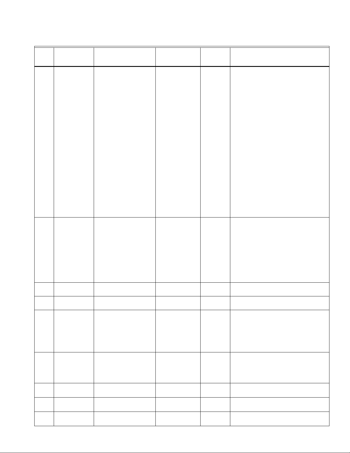
Table 2. Installer Setup (ISU) Table. (Continued)
VISIONPRO® 8000 WITH WI-FI
®
ISU
Number
Installer Setup
Name Settings Default
408 Max. Cool
Recovery Outdoor
Temp
409 Adaptive Recovery
Off
-20° F to 100°F
No
Yes
Residential,
Commercial
or Both Notes
70° F Commercial Off: The cooling system will begin recovery at
the time that is scheduled.
When a Maximum Recovery Ramp Rate is set,
the thermostat will begin recovery early to
ensure the temperature is reached at the
scheduled time.
Set a Maximum Recovery Ramp Rate based on
the rate that the cooling system can recover at
for a mild day in your region. Default setting is
6° F / hour.
Set an Outdoor Temperature that is
representative of a mild day in your region to be
associated with the Maximum Recovery Ramp
Rate.
The thermostat will begin recovery at the
optimal time based on a calculated ramp rate,
allowing the system to recover on time and save
energy during changing outdoor conditions.
During recovery, the setpoint changes at a rate
in degrees per hour depending on the outdoor
temperature.
Yes Residential No: The system will begin heating or cooling
recovery at the scheduled time.
410 Minimum Cool
Setpoint
410 Maximum Heat
Setpoint
411 Keypad Lockout
500 Wired Sensor on
S Terminals
500 Wired Remote
Indoor Sensor
500 Wired Outdoor
Sensor
500 Wired Discharge
Sensor
50° F to 99° F
40° F to 90° F
Unlocked
Partially Locked
Fully Locked
No
Yes
No
Yes
No
Yes
No
Yes
Yes: The thermostat will begin heating or
cooling recovery early to ensure that the
temperature is reached at the scheduled time.
The thermostat will adjust the start time of the
equipment based on how quickly the scheduled
temperature was reached on previous days. See
page 52 for more information on Adaptive
Intelligent Recovery.
50° F Both The user cannot set the temperature below this
level.
90° F Both The user cannot set the temperature above this
level.
Unlocked Both Unlocked: User has access to all thermostat
settings.
Partially Locked: User can modify only
temperature settings.
Fully Locked: User cannot modify any settings.
No Both This ISU is only displayed if ISU 106 was
configured to Wired/Internet.
Select Yes if a wired indoor, outdoor, or
discharge sensor is wired to S1.
No Both Select Yes if a wired indoor sensor is wired to
S1.
No Both Select Yes if a wired outdoor sensor is wired to
S1.
No Both Select Yes if a wired discharge sensor is wired
to S1
27 33-00096—01

VISIONPRO® 8000 WITH WI-FI
®
Table 2. Installer Setup (ISU) Table. (Continued)
ISU
Number
Installer Setup
Name Settings Default
501 Indoor Sensor
Name
502 Indoor Sensor
503 Indoor Sensor
Type
504
Use [T-Stat Sensor]
for Temp Ctrl
505 Outdoor Sensor
509 Discharge Sensor
510 Discharge Sensor
Type
[Select Indoor Sensor Name]
S1
10K
20K
Use T-Stat Sensor for Temp Ctrl Yes or No
S1
S1
10K
20K
Residential,
Commercial
or Both Notes
Indoor Sensor Both Select a name (location) of the Wired Remote
Indoor Sensor.
Both Confirms type of sensor wired to S1.
10K:
if ISU 101
Both Select 10K or 20K based on the sensor
installed. Refer to resistance values below:
Application is
Residential
C7189U1005 = 10K ohm
C7772 = 20K ohm
20K:
if ISU 101:
Application is
Commercial
TR21 = 20K ohm
TR21-A = 10K ohm (IMPORTANT - the TR21-A
must be used in combination with a TR21
sensor or another TR21-A sensor for the
thermostat to calculate the correct indoor
temperature reading).
See “Wiring guide — Wired Indoor Sensors”
beginning on page 88 for information on the
sensor type you should select based on how the
sensors are wired. For example, you would
select 20K when you have two TR21-A (10K)
sensors wired in series.
Sensors are
Averaged (T-Stat
Sensor and Remote)
Both Only displayed when a wired indoor sensor is
configured. Select Yes if you want the
thermostat to average with wired indoor sensor.
Select No if you want to sense temperature only
at the wired sensor.
Both Confirms type of sensor wired to S1.
Both Confirms type of sensor wired to S1.
10K Both Select 10K or 20K based on the sensor
installed. Refer to resistance values below:
511 A-Coil Low Temp.
Cutoff
700 Filter Type
702 Number of Air
Filters
711 Air Filter 1
Reminder
Note: “1” is not
displayed if there
is only 1 filter.
Off
35° F to 65° F (in 5° F
increments)
None
Elec. Air Cleaner
Media
1 to 2
Off
Run Time:
10, 20, 30, 45, 60, 90, 120, 150
days
Calendar:
30, 45, 60, 75 days
3, 4, 5, 6, 9, 12, 15 months
50062329-001 = 10K ohm
32005180-002 = 10K ohm
C7735A1000 = 10K ohm
C7770A = 20K ohm
C7041 = 20K ohm
Off Both If an optional Discharge Sensor is used, this
feature can help prevent icing on the air
conditioning A-Coil.
When temperature reaches the limit you set,
compressor(s) will shutoff while the system fan
continues to run, until the temperature rises to a
safe level.
Media Both
1 Both
Off Both
33-00096—01 28

Table 2. Installer Setup (ISU) Table. (Continued)
VISIONPRO® 8000 WITH WI-FI
®
ISU
Number
Installer Setup
Name Settings Default
711 Air Filter 2
Reminder
712 EAC Cell
Reminder
712 EAC Pre-Filter
Reminder
712 EAC Post Filter
Reminder
800 Humidifier Type
803 Humidifier Wiring
805 Window
Protection
Off
Run Time:
10, 20, 30, 45, 60, 90, 120, 150
days
Calendar:
30, 45, 60, 75 days
3, 4, 5, 6, 9, 12, 15 months
Off
Calendar Months:
6, 7, 8, 9, 10, 11, 12 months
Off
Calendar Months:
3, 4, 5, 6 months
Off
Calendar Months:
6, 7, 8, 9, 10, 11, 12 months
None
Steam
Bypass / Fan Pwrd
U1
Off
On
Residential,
Commercial
or Both Notes
Off Both
Off Both Electronic Air Cleaner Cell Cleaning Reminder
Off Both Electronic Air Cleaner Pre-Filter Cleaning
Reminder
Off Both Electronic Air Cleaner Post-Filter Replacement
Reminder
None Both
Thermostat defaults
to the unused
universal terminal
Both U1 are dry contacts that require power. See
“Wiring IAQ Equipment or a Heat/Cool Stage to
the Universal Terminals” beginning on page 86.
U1.
Off Both Requires a wired outdoor sensor or connection
to the Internet.
Off: The thermostat controls the humidity level
to the user's desired humidity setting. Frost or
condensation may appear on windows.
On: The thermostat prevents frost or
condensation on windows by not allowing the
humidifier to run above a certain level. To
prevent frost or condensation, the thermostat
may turn off the humidifier before the humidity
setting is reached. See “Window Protection”
beginning on page 58.
29 33-00096—01

VISIONPRO® 8000 WITH WI-FI
®
Table 2. Installer Setup (ISU) Table. (Continued)
ISU
Number
Installer Setup
Name Settings Default
806 User Humidifier in
Heat Mode
Use Humidifier in
Cool Mode
Use Humidifier in
Off Mode
807 Humidifier Control
User Humidifier in Heat Mode No or Yes
Use Humidifier in Cool Mode No or Yes
Use Humidifier in Off Mode - No
or Yes
Hum when Heat is On
Hum when Fan is On
Tstat Controls Fan
Hum Controls Fan
User Humidifier in
Heat Mode - Yes
Default varies based
on heating/cooling
equipment selected
Defaults to Hum
when Heat is On
when ISU 800
Humidifier Type is
Bypass or Fan Pwrd
Defaults to
Tstat Controls Fan
when ISU 800
Humidifier Type is
Steam
Residential,
Commercial
or Both Notes
Both Heat: Includes Heat, Emergency Heat and Auto.
If the system is in Auto mode, the thermostat
will allow humidification if the last call was for
heat.
Cool: Includes Cool and Auto. If the system is in
Auto mode, the thermostat will allow
humidification if the last call was for cool. A
discharge air temperature sensor is required to
humidify in the Cool mode.
Off: The thermostat will allow humidification
when the system setting is Off.
See “Set up Humidification” beginning on
page 58.
Both Hum when Heat is On: The thermostat turns on
the humidifier only if the heat is currently
running and humidification is needed.
Hum when Fan is On: The thermostat turns on
the humidifier only if the fan is currently running
and humidification is needed.
Tstat Controls Fan: The thermostat turns on the
humidifier and the fan when humidification is
needed.
808 Run Humidifier
when Cool is On
810 Hum Tank / Filter
Reminder
810 Humidifier Pad
Reminder
900 Dehumidification
Equipment
Yes
No
Off
60 Run Time Days
90 Run Time Days
6 Calendar Months
12 Calendar Months
Off
60 Run Time Days
90 Run Time Days
6 Calendar Months
12 Calendar Months
Residential:
None
A/C with Low Fan
A/C with High Fan
Dehumidifier
Commercial:
None
A/C with Low Fan
A/C with High Fan
Hot Gas Bypass
Dehumidifier
Hum Controls Fan: The thermostat turns on the
humidifier when humidification is needed and
the humidifier controls the fan.
Yes Both Yes: Humidifier can run when the cooling
system is on.
No: Humidifier can NOT run when the cooling
system is on.
Off Both This ISU is only displayed if ISU 800 Humidifier
Type is Ste am.
Run Time Days are not shown if ISU 800
Humidifier Type is set to None.
Off Both This ISU is only displayed if ISU 800 Humidifier
Type is Bypass or Fan Pwrd.
Run Time Days are not shown if ISU 800
Humidifier Type is set to None.
None Both See “Dehumidification - Residential” beginning
on page 60 or “Dehumidification - Commercial”
beginning on page 64.
33-00096—01 30

Table 2. Installer Setup (ISU) Table. (Continued)
VISIONPRO® 8000 WITH WI-FI
®
ISU
Number
Installer Setup
Name Settings Default
904 Dehum Wiring
905 Dehum Terminal -
U1
907 Dehum Over
Cooling Limit
U1
Normally Closed
Normally Open
0°, 1°, 2°, 3° F
Residential,
Commercial
or Both Notes
Thermostat defaults
to the unused
universal terminal
Both U1 are dry contacts that require power. See
“Wiring IAQ Equipment or a Heat/Cool Stage to
the Universal Terminals” beginning on page 86.
U1.
Defaults to Normally
Closed when ISU
Both Choose an option appropriate for the type of
equipment installed.
900 Dehum
Equipment is A/C
with Low Fan
Normally Open: U1 will normally be open and
will close when the thermostat calls for
dehumidification.
Defaults to Normally
Open when ISU 900
Dehum Equipment is
Hot Gas Bypass
Normally Closed: U1 will normally be closed
and will open when the thermostat calls for
dehumidification.
3° F Residential This ISU is only displayed when ISU 900 Dehum
Equipment is set to A/C with Low Fan or A/C
with High Fan.
The thermostat uses the cooling system to
reduce humidity by lowering the temperature up
to 3° F below the current cool setpoint until the
desired humidity level is reached.
The thermostat keeps the temperature below
the cooling setpoint until the desired humidity
level is reached.
908 DehumControl
909 Dehum Minimum
On Time
910 Dehum Over
Cooling Limit
Basic
Minimum On Time
Cooling Droop
Reheat
5 to 15 minutes
1° F to 5° F
0° F is only an option when ISU 900 Dehum
Equipment is set to A/C with Low Fan.
Basic Commercial See “Dehumidification - Commercial” beginning
on page 64.
10 minutes Commercial This ISU is only displayed if ISU 908 Dehum
Control is set to Minimum On Time. This option
ensures that the compressor runs long enough
to effectively reduce humidity when the cooling
equipment is cycled on. The compressor will
run for the “minimum on time” you set until the
desired humidity level is reached.
2° F Commercial This ISU is only displayed if ISU 908 Dehum
Control is set to Cooling Droop. The thermostat
uses the cooling system to reduce humidity by
lowering the temperature up to 5° F below the
current cool setpoint until the desired humidity
level is reached.
The thermostat keeps the temperature below
the cooling setpoint until the desired humidity
level is reached.
31 33-00096—01

VISIONPRO® 8000 WITH WI-FI
®
Table 2. Installer Setup (ISU) Table. (Continued)
ISU
Number
Installer Setup
Name Settings Default
912 User Dehumidifier
in Heat Mode
Use Dehumidifier
in Cool Mode
Use Dehumidifier
in Off Mode
913 Dehum Fan
Control
914 Run Dehumidifier
when Cool is On
User Dehumidifier in Heat Mode
- No or Yes
Use Dehumidifier in Cool Mode -
No or Yes
Use Dehumidifier in Off Mode -
No or Yes
Tstat Controls Fan
Equip Controls Fan
Yes
No
Residential,
Commercial
or Both Notes
Use Dehumidifier in
Cool Mode - Yes
Default varies based
on heating/cooling
equipment selected
Both This ISU is only displayed when ISU 900 Dehum
Equipment is set to Dehumidifier.
Heat: Includes Heat, Emergency Heat and Auto.
If the system is in Auto mode, the thermostat
will allow dehumidification if the last call was for
heat.
Cool: Includes Cool and Auto. If the system is in
Auto mode, the thermostat will allow
dehumidification if the last call was for cool.
Off: The thermostat will allow dehumidification
when the system setting is Off.
See “Dehumidification - Residential” beginning
on page 60 or “Dehumidification - Commercial”
beginning on page 64.
Tstat Controls Fan Both This ISU is only displayed when ISU 900 Dehum
Equipment is set to Dehumidifier.
Tstat Controls Fan: The thermostat turns on the
dehumidifier and the fan when dehumidification
is needed.
Equip Controls Fan: The thermostat turns on the
dehumidifier when dehumidification is needed.
The fan is controlled by the equipment.
Yes Both This ISU is only displayed when ISU 900 Dehum
Equipment is set to Dehumidifier.
918 Dehum Away
Mode
919 Dehum Away
Mode Fan Setting
920 Dehum Away
Mode Low Limit
Temp
920 Dehum Away
mode Temp
Setting
920 Dehum Away
mode Dehum
Setting
Not Allowed
Allowed
Automatic
On
Circulate
70° F to 80° F
70° F to 99° F
40% to 70% (in 5% increments)
Yes: Dehumidifier can run when the cooling
system is on.
No: Dehumidifier can NOT run when the cooling
system is on.
Not Allowed Both This ISU is NOT displayed when ISU 900
Dehum Equipment is None.
ISU 919 to 920 are only displayed when ISU
918 Dehum Away Mode is Allowed.
See “Dehumidification Away Mode” beginning
on page 63.
Automatic Both The On and Circulate settings may re-introduce
humidity into the living space.
76° F Both If the cooling system is used to control humidity
while Dehumidification Away Mode is active, the
thermostat allows the cooling system to lower
the indoor air to the Low Limit Temperature
Setting to reach the dehumidification setting at
ISU 920.
85° F Both The temperature maintained while
Dehumidification Away Mode is active and the
desired humidity level is satisfied.
65% Both The desired humidity level while
Dehumidification Away Mode is active.
33-00096—01 32

Table 2. Installer Setup (ISU) Table. (Continued)
VISIONPRO® 8000 WITH WI-FI
®
ISU
Number
Installer Setup
Name Settings Default
921 Dehumidifier Filter
Reminder
1000 Ventilation Type
1002 Ventilation Wiring
1005 Ventilation
Method
Off
30, 60, Calendar Days
3 to 12 Calendar Months (in 1
month increments)
None
ERV / HRV
Passive (Fan Only)
Fresh Air Damper
None
U1
ASHRAE
Percent On Time
Residential,
Commercial
or Both Notes
Off Both
None Both None: The thermostat does not control
ventilation.
ERV/HRV: The thermostat controls an Energy
Recovery Ventilator or Heat Recovery Ventilator
for ventilation.
Passive (Fan Only): The thermostat turns on the
fan for ventilation.
Fresh Air Damper: The thermostat turns on the
fan and opens a fresh air damper for ventilation.
Thermostat defaults
to the unused
Both Number of Universal Outputs:
TH8321 Thermostat: U1 terminals
universal terminal
U1.
U1 are dry contacts that require power. See
“Wiring IAQ Equipment or a Heat/Cool Stage to
the Universal Terminals” beginning on page 86.
Defaults to
ASHRAE
Both See “Ventilation Control Methods (ISU 1005)”
beginning on page 68.
when ISU 101
Application is set to
Residential.
1006 Vent Fan Control
1009 Number of
Bedrooms
1009 Size of House
1010 Ventilation Rate
1012 Vent Percent On
Time
Tstat Controls Fan
Equip Controls Fan
1 to 6
1000 to 5000 sq. ft. (in 100 sq.
ft. increments)
(90 to 460 sq. m.)
30 to 350 CFM (in 5 CFM
increments)
(850 - 9900 LPM)
10% to 100% (in 10%
increments)
Percent on Time is
the only choice when
ISU 101 Application
is set to Commercial.
Tstat Controls Fan Both Tstat Controls Fan: The thermostat turns on the
ventilation equipment and the fan when
ventilation is needed.
Equip Controls Fan: The thermostat turns on the
ventilation equipment when ventilation is
needed. The fan is controlled by the equipment.
2 bedrooms Residential This ISU is only displayed when ISU 1005
Ventilation Method is set to ASHRAE
(Residential only).
1000 sq. feet Residential This ISU is only displayed when ISU 1005
Ventilation Method is set to ASHRAE
(Residential only).
150 Residential This ISU is only displayed when ISU 1005
Ventilation Method is set to ASHRAE
(Residential only).
30% Both The thermostat operates ventilation equipment
based on a percentage entered in the installer
setup (ISU 1012). For example, if Percent on
Time is set to 50%, the ventilation equipment
will run at random times during a 1 hour period
until it reaches a 50% run time (approximately
30 minutes).
33 33-00096—01

VISIONPRO® 8000 WITH WI-FI
®
Table 2. Installer Setup (ISU) Table. (Continued)
ISU
Number
Installer Setup
Name Settings Default
1012 Vent Priority
Lockouts
ASHRAE
Residential,
Commercial
or Both Notes
Lockouts Residential Lockouts are Priority: The thermostat places a
priority on lockouts versus the ASHRAE 62.2
ventilation standard. The thermostat will not run
ventilation during the following lockout
conditions (if configured) unless you manually
call for ventilation:
• Lockout Ventilation during Outdoor Conditions
(ISU 1013)
• Lockout Ventilation on Humidification or
Dehumidification Calls (ISU 1014)
• Lockout Ventilation during “Sleep” (Residential)
or “Unoccupied” (Commercial) program periods.
Note: This option is set by the user on the
Ventilation screen in the Menu.
ASHRAE is Priority: ASHRAE requires
additional ventilation following a long off cycle.
The thermostat meets the ASHRAE 62.2
ventilation standard by running additional
ventilation when outdoor conditions are
favorable. If ASHRAE cannot be met when
outdoor conditions are favorable, the
thermostat will override the outdoor lockouts
and run ventilation. When using this option, it is
recommended to increase the rate (CFM) of the
ventilation equipment to meet the ASHRAE 62.2
ventilation standard in a shorter run time.
1013 Low Outdoor
Temp Vent
Lockout
1013 High Outdoor
Temp Vent
Lockout
1013 High Out. Dew
Point Vent
Lockout
Off
-20° F to 40° F (in 5° F
increments)
Off
80° F to 110° F (in 5° F
increments)
Off
65° F to 85° F (in 5° F
increments)
Notes:
• ISU 1014 Lockout Ventilation on Humidification or
Dehumidification calls is not an option when you
select ASHRAE is Priority.
• The ability to lockout ventilation during the
“Sleep” or Unoccupied program periods is not an
option when you select ASHRAE is Priority.
Off Both Requires an outdoor sensor.
This ISU is only displayed when ISU 1000
Ventilation Type is set to ERV / HRV or Fresh Air
Damper.
See “Ventilation — Outdoor Condition Lockouts
(ISU 1013)” beginning on page 68.
Off Both Requires an outdoor sensor.
This ISU is only displayed when ISU 1000
Ventilation Type is set to ERV / HRV or Fresh Air
Damper.
See “Ventilation — Outdoor Condition Lockouts
(ISU 1013)” beginning on page 68.
Off Both Requires Internet connection.
This ISU is only displayed when ISU 1000
Ventilation Type is set to ERV / HRV or Fresh Air
Damper.
33-00096—01 34
See “Ventilation — Outdoor Condition Lockouts
(ISU 1013)” beginning on page 68.

Table 2. Installer Setup (ISU) Table. (Continued)
VISIONPRO® 8000 WITH WI-FI
®
ISU
Number
Installer Setup
Name Settings Default
1014 Vent During Hum
or Dehum Calls
1016 Vent On High
Indoor Humidity
1017 Ventilator Core
Reminder
1017 Ventilator Filter
Reminder
1100 Number of UV
Devices
1105 UV Bulb 1
Reminder
Yes
No
Off
On
Off
3, 6, 9, 12 Calendar Months
Off
3, 6, 9, 12 Calendar Months
0, 1, 2
Off, 6, 12, 24 Calendar Months
Residential,
Commercial
or Both Notes
Yes Both This feature is used to help reach the user's
desired humidity level by not allowing the
ventilation equipment to run during a call for
humidification or dehumidification.
Yes: Ventilation is allowed to run during a call
for humidification or dehumidification.
No: Ventilation is NOT allowed to run during a
call for humidification or dehumidification.
On Both This ISU is only displayed when ISU 1000
Ventilation Type is set to ERV / HRV.
Off: The humidity level has no effect on
ventilation.
On: The thermostat removes excess humidity
by turning on the ventilator when the indoor
humidity rises 10% above the user's
humidification setting. The thermostat must be
in the heat mode to ventilate on high humidity.
Off Both Ventilator Core Cleaning Reminder
Off Both Ventilator Filter Cleaning Reminder
0 Both Press the up/down arrows to select the number
of UV devices installed in the system. Some
systems may have two UV devices, one for the
A-Coil and another for Air Treatment. A
replacement reminder can be setup for each
one. Select 0 if no UV devices are installed.
Off Both UV Bulb 1 Replacement Reminder
Note: “1” is not
displayed if there
is only 1 UV Bulb
1105 UV Bulb 2
Reminder
1200 Custom
Reminders
28 Backlighting
1400 Clock Format
1401 Daylight Saving
Time
Off, 6, 12, 24 Calendar Months
View / Edit Custom Reminders
Add Custom Reminders
On Demand
Continuous
12 hour
24 hour
Off
On
Off Both UV Bulb 2 Replacement Reminder
None Both See “Customizable Reminders” beginning on
page 73.
On Demand Both Select Continuous or On Demand backlighting.
Select Continuous backlighting if you would like
the backlight to be on all the time.
Select On Demand backlighting if you would like
the backlight to only turn on after a key press.
After you complete your changes, the screen
stays lit for 45 seconds.
12 Both
On Both Set to Off in areas that do not follow Daylight
Saving Time.
35 33-00096—01

VISIONPRO® 8000 WITH WI-FI
®
Table 2. Installer Setup (ISU) Table. (Continued)
ISU
Number
Installer Setup
Name Settings Default
1402 Indoor
Temperature
Offset
1402 Indoor Humidity
Offset
1404 Alert Light
Indicator
1500 Dealer Name
1500 Dealer Phone
1501 Dealer Email
Address
1501 Dealer Website
1502 Dealer Message
-3° F to 3° F (in 1° F increments)
-12% to 12% (in 1% increments)
On
Off
[Dealer Name]
[Dealer Phone]
[Dealer Email Address]
[Dealer Website]
[Dealer Message]
Residential,
Commercial
or Both Notes
0° F Both 0° F - No difference in displayed temperature
and the actual room temperature.
The thermostat displays up to 3°F (1.5°C) lower
or higher than the actual measured
temperature.
0% Both 0% - No difference in displayed humidity and
the actual room humidity.
The thermostat displays up to 12% lower or
higher than the actual measured humidity.
On Both The thermostat has a built in light indicator.
When an alert is active, the light will be on
continuous if the thermostat is powered with 24
VAC (C wire) or it will flash if the thermostat is
powered with batteries only. The light also turns
on when the system setting is set to Em Heat.
Select On to use the light indicator or select Off
to turn off the light.
None Both Dealer information is displayed to the user when
None Both
None Both
an alert is active and the user can access this
information by selecting "Dealer Information" in
the Menu.
None Both
None Both
33-00096—01 36

Connect to Wi-Fi® Network
DoaIol Inrol Madorl
Wi-Fi Setup
Installer Options
M35352
M35349
Finding Networks
Please Wait
M35347
Select Wi-Fi Network
Your Network
M35350
Enter Password
Press Here to Edit
M35346
Delete Space
AC
M35360
M35351
Connection
Successful
M35361A
Register at:
Honeywell.com/TCC
1. Touch MENU
2. Select Wi-Fi Setup.
The thermostat will scan for available Wi-Fi networks.
3. The screen displays “Finding Networks Please Wait”
after which it displays a list of all Wi-Fi networks it can
find.
4. Find the name of the network you want to use by
pressing the arrow buttons to scroll up/down or left/right.
Press the Wi-Fi network name, then press Select.
NOTE: If the Wi-Fi network name is hidden, see
“Connecting to a hidden Wi-Fi network” on
page 38.
5. When prompted, press the screen to edit the password
(if necessary).
6. Enter the password.
Press the or buttons to change the letter or
number. Press the button to move to the next
character, or the button to move to the previous
character. Use the or buttons at the bottom to
change letter case. Press Done when complete.
7. The screen will let you know when the connection is
successful.
Press Done when the connection is successful.
If the connection is not successful, the screen will explain
why not. See “Unsuccessful connection” on page 38.
Follow instructions on the screen to try again.
VISIONPRO® 8000 WITH WI-FI
®
NOTE: Press the for more information about an
unsuccessful connection.
8. If you want remote access to the thermostat, you must
set up an account at mytotalconnectcomfort.com and
add the thermostat to the account.
NOTE: You will need the thermostat MAC and CRC IDs to
add the thermostat. They are on the screen under
Menu, Wi-Fi Setup and on the Thermostat ID Card
packed with the thermostat.
37 33-00096—01

VISIONPRO® 8000 WITH WI-FI
DoaIol Inrol Madorl
Wi-Fi Setup
Installer Options
M35352
M35353
WirelessNetwork
Other...
M35354
Enter Network Name
Press Here to Edit
M35346
Delete Space
AC
M35355
SSID Security
Open Network
®
Connect to a hidden Wi-Fi® network
1. Touch MENU, then Wi-Fi Setup.
2. Touch Other, then Select.
3. When prompted, press the screen to edit the network
name.
4. Enter the network name.
Press the or buttons to change the letter or
number. Press the button to move to the next
character, or the button to move to the previous
character. Use the or buttons at the bottom to
change letter case. Press Done when complete.
5. Select the appropriate network security setting, then
press Select.
6. Enter the Wi-Fi network password as explained above in
“Connecting to Wi-Fi Network”, step 6.
Unsuccessful Wi-Fi connection
If you are unsuccessful in connecting the thermostat to the
Wi-Fi network, you will see a Connection Failed screen. Press
button for other tips about this failed connection. Here are
three specific reasons the connection might be unsuccessful.
For all Connection Failed screens, pressing Done will return to
the Menu screen.
Invalid Password
The password you entered is invalid. Check that you have the
right password and try again.
No IP Address
The thermostat was unable to obtain an IP address from the
router. Verify the router is correctly set up to automatically
assign IP addresses. This connection can take several
minutes. If there is still no connection, remove the thermostat
from the wallplate for 10 seconds, then snap it back into place.
No Internet Link
The thermostat connected to the Wi-Fi network but was unable
to establish a connection to the internet. Check the router
settings and try again. Make sure the Ethernet cable is plugged
into the router and try rebooting the router if necessary.
33-00096—01 38

INSTALLER TESTS
CAUTION
Use the installer tests to check out the system:
• Equipment Test: Tests the heating, cooling, fan, and IAQ
equipment. The test allows you to manually call for each
system to ensure the equipment and thermostat operate
properly. Any minimum off timers are ignored during the
system test. You can test the following equipment:
—Heat
—Em Heat
—Cool
—Fan
— Humidification
— Dehumidification
— Ventilation
— Economizer
— Time of Day
Accessing Installer Test
1. Press MENU on the home screen, then scroll down to
Installer Options and press SELECT.
2. Enter the password (date code) when prompted. See
“Finding Your Password (Date Code) to Access Installer
Options” beginning on page 9 for more information.
3. Scroll down to Installer Test and press SELECT.
VISIONPRO® 8000 WITH WI-FI
Fig. 24.
Fig. 25.
®
Fig. 23.
Equipment Damage Hazard.
Minimum compressor off time is bypassed during
the Equipment Test
Avoid cycling compressor quickly.
Using the Installer Test
1. Select the equipment you want to test and press the
arrow buttons to turn the equipment on/off. Press Back to
test the remaining equipment.
NOTE: The time out for the Equipment Test mode is 30
minutes (if there is no keypress for 30 minutes,
the thermostat will automatically exit the Equipment Test).
2. Run Time and Discharge temperature are displayed for
heating and cooling tests (requires Discharge Air Sensor). See Fig. 26.
The Discharge temperature updates every 30 seconds
during the test. The Run Time counter starts over when
the next stage is turned on.
Fig. 26.
39 33-00096—01

VISIONPRO® 8000 WITH WI-FI
M7514
HOME. Touch to display Home screen.
FAN. Select fan mode.
SYSTEM. Select system mode (Heat/Cool).
MENU. Touch to display options. Start here to set a
program schedule.
Current status. Shows system mode (heat/cool),
outdoor temperature (with optional outdoor sensor
or Wi-Fi
® connection) and humidity (requires Wi-Fi
connection).
Current schedule. Touch an arrow to change
temperature setting and select a Temporary or
Permanent Hold.
Indoor conditions. Shows indoor temperature and
humidity.
Current time. Touch to set the current time/date.
Alert Light. On when alert message is active or
system is set to EmHeat.
®
MOUNTING C7089U1006 WIRED OUTDOOR
TEMPERATURE SENSOR
Do not mount the sensor:
• in direct sunlight.
• where hot or cold air blows on the sensor. Discharge line
from an outdoor compressor unit, vent or fan causes
inaccurate temperature readings.
• where snow, ice or debris can cover it.
Use the following steps to mount the sensor:
1. Remove the sensor from the mounting clip.
2. Mark the area on the location selected for mounting the
sensor mounting clip.
3. Mount the clip.
4. See “Wiring C7089U1006 Outdoor Sensor” on page 87.
Fig. 27. Typical locations for C7089U1006 Outdoor Sensor.
OPERATION
Fig. 28. Quick reference to residential display.
NOTE: The screen lights when you press any button. After you complete your changes, the screen stays lit for 45
seconds. Depending on how your thermostat was installed, the screen light may always be on.
33-00096—01 40

VISIONPRO® 8000 WITH WI-FI
HOME. Touch to display Home screen.
FAN. Select fan mode.
SYSTEM. Select system mode (Heat/Cool).
MENU. Touch to display options. Start here to set a program
schedule.
Current status. Shows system mode (heat/cool), outdoor
temperature (with optional outdoor sensor, or Wi-Fi
® connection)
and humidity (requires Wi-Fi connection).
Override. Touch to override program schedule.
Current schedule. Touch an arrow to change temperature setting
and set a Temporary Hold.
Current program status.
Indoor conditions. Shows indoor temperature and humidity.
Current time. Touch to set the current time/date.
Alert Light. On when alert message is active or system is set to
EmHeat.
MCR34092
MCR34155
Select Option
Time Date
MCR34094
Please Set Time
6
:30 PM
MCR34096
®
Fig. 29. Quick reference to commercial display.
NOTE: The screen lights when you press any button. After you complete your changes, the screen stays lit for 45
seconds. Depending on how your thermostat was installed, the screen light may always be on.
Setting the Time/Date
1.
Touch the current time. The screen displays Select Option.
Fig. 32.
5. Touch Home to redisplay the Home screen.
Fig. 30.
2. Touch Time or Date, then touch Select.
NOTE: The date is not shown on the home screen; how-
ever, it should be set to allow the thermostat to
adjust time automatically for daylight saving time
and for other features such as vacation hold.
Setting the Fan
1. Touch FAN to display fan settings.
Fig. 31.
3. Touch or until the proper time/date is displayed.
4. Touch Done to save or Cancel to ignore changes.
Fig. 33.
2. Touch On, Auto, Circ, or Follow Schedule.
41 33-00096—01

VISIONPRO® 8000 WITH WI-FI
MCR34097
On Auto Circ
MCR34098
MCR34099
Heat Cool Auto
Off
MCR34100
MCR34101
Edit Schedule
View Schedule
MCR34102
Use Scheduling
Assistant?
®
3. Touch Done to save and exit.
• On: Fan is always on.
• Auto: Fan runs only when heating or cooling system is
on.
• Circ: Fan runs randomly, about 35% of the time
(residential only).
• Follow Schedule: Fan controlled by program. This
option may not appear, depending on how your fan
was programmed.
Fig. 34.
NOTE: In commercial use, touch Auto or On to temporar-
ily override the programmed fan schedule.
Setting System Mode
1. Touch SYSTEM to display system settings.
Preset Energy-Saving Schedules
These default Energy Saver settings can reduce expenses.
Table 3. Residential Use Default Schedule.
Period
Wake 6:00 am 70° 78° 70° 78°
Leave 8:00 am 62° 85° 62° 85°
Return 6:00 pm 70° 78° 70° 78°
Sleep 10:00 pm 62° 82° 62° 82°
Occupied 1 8:00 am 70° 75° On
Unoccupied 1 10:00 pm 55° 85° Auto
Occupied 2* 12:00 am 70° 75° On
Unoccupied 2* 12:00 am 55° 85° Auto
* Period 2 is cancelled by default. If you activate it, the values
shown above are default settings.
Start
Time
Table 4. Commercial Use Default Schedule.
Period Start Time Heat Cool Fan
Heat
(Mon-Fri)
Cool
(Mon-Fri)
Heat
(Sat-Sun)
Cool
(Sat-Sun)
Adjusting Program Schedules
1. Touch MENU.
Fig. 35.
2. Touch desired option
• Heat: Controls only the heating system.
• Cool: Controls only the cooling system.
• Off: Heating/cooling systems are off.
• Auto: Selects heating or cooling depending on the
indoor temperature.
• Em Heat (heat pumps with aux. heat): Controls
auxiliary/emergency heat. Compressor is locked out.
Fig. 36.
3. Touch Done to save and exit.
NOTE: The Auto and Em Heat system settings may not
appear, depending on how your thermostat was
installed.
Fig. 37.
2. Select Edit Schedule to display Use Scheduling Assis-
tant?
Fig. 38.
• Touch Yes to create a schedule by answering simple
questions.
• Touch No to manually create a program schedule.
33-00096—01 42
Fig. 39.

VISIONPRO® 8000 WITH WI-FI
MCR34151
Select the days
to schedule
MCR34152
Set Wake
time & temperature
MCR34103
Temporary Hold
Permanent Hold
®
NOTE: To reduce costs, use the “Preset Energy-Saving
Schedules” on page 42.
3. Select the days to schedule, touch Next.
Fig. 40.
4. Touch or to set your Wake time for selected day(s).
5. Touch or to set Heat and Cool temperatures for the
Wake period.
6. Touch other time periods (Leave, Return, Sleep) to set
time and temperatures for each.
7. Touch Done to save and exit (Touch Cancel to exit without saving changes).
Overriding Schedules: Residential
Use
1. Touch or to adjust the temperature (right side of
screen) and the Hold Until time (left side). The schedule
will resume when the Hold Until time expires.
Fig. 42.
2. Select Permanent Hold to keep the same temperature
until you change it or resume the program schedule.
Touch Cancel Hold at any time to resume the program
schedule.
Overriding Schedules: Commercial
Use
Touch or to adjust the temperature. It will be maintained
until the hold time you set.
• To change the hold time, touch the Hold Until arrow buttons.
This time can be adjusted up to the maximum time set by
the installer.
Fig. 41.
NOTE: Touch Cancel Period to eliminate any unwanted
time period.
Touch Fan Setting to customize fan settings for
any time period.
MCR34169
Fig. 43.
• Touch Override to use a pre-set occupied temperature if a
person uses the room during an unoccupied period. The
new temperature will be maintained for 1 hour and can be
adjusted up to the maximum time set by the installer.
43 33-00096—01

VISIONPRO® 8000 WITH WI-FI
MCR34106
MCR34100
MCR34108
Equipment Status
Date/Time
MCR34109
Heat Stage 1: Off
Cool Stage 1: On
MCR34100
MCR34110
Vacation Mode
Equipment Status
MCR34111
Date You Leave
Jul 17, 2012
MCR34112
Jul 25 - Jul 26
Heat: 72 Cool: 78
The programmed schedule will resume when the override timer
expires. Touch Cancel Hold at any time to resume the program
schedule.
®
Fig. 44.
Viewing Equipment Status
1. Touch MENU.
Setting Vacation Hold: Residential
Use
This feature helps you save energy while you are away, and
restores comfortable settings just before you return home.
1. Touch MENU.
Fig. 48.
2. Select Vacation Mode.
Fig. 49.
Fig. 45.
2. Select Equipment Status.
Fig. 46.
3. Touch or to view the status of all the equipment
your thermostat is controlling. Depending on how your
thermostat was installed, the Equipment Status screen
can report data about the following systems:
• Heating and cooling
•Fan
• Humidification
• Dehumidification
• Ventilation
• Maintenance reminders
• Thermostat information
3. Touch or to select the date you leave, then touch
Next for further scheduling details, including times of day,
temperature settings, return date, and return settings.
Fig. 50.
4. Review your selections on the last display, and touch
Done to save your settings. Touch Cancel to ignore the
changes.
Fig. 51.
33-00096—01 44
Fig. 47.
Setting Holiday/Event Schedules:
Commercial Use
This feature helps you conserve energy when the workplace is
unoccupied for special events and holidays.

VISIONPRO® 8000 WITH WI-FI
MCR34100
MCR34113
Holiday Schedule
Holiday Mode
MCR34114
Custom Events
US Holidays
MCR34114
Custom Events
US Holidays
MCR34116
Create New Event
MCR34117
Select Occurence
Specific Date
MCR34118
Schedule adjusted
to 62 in heating
®
1. Touch MENU.
Fig. 52.
2. Select Holiday Schedule.
Fig. 53.
3. Select the item you want to schedule and touch Next for
further scheduling details.
• Custom Events lets you set up other days for special
schedules.
• US and Canadian Holiday options let you select from
a list of holidays commonly observed in each country.
2. Select Create New Event.
Fig. 56.
3. Select Specific Date or Month/Weekday.
• For Specific Date, you are prompted to select the
event’s start date, settings, end date, and frequency.
• For Month/Weekday, you are prompted to select the
month, day of the week, week of the month, settings,
length of event, and frequency for the event.
Fig. 54.
4. Make selections as prompted on each screen. For more
information, see next two pages.
5. Touch Done to save your settings.
Setting Custom Events: Commercial
Use
This feature lets you customize temperature settings to be
maintained during a specific event. You can set up an event for
a specific date or day in a month. The thermostat resumes
normal scheduling after the event. The thermostat can be
scheduled for up to 25 Custom Events.
1. Select Custom Events from the Holiday Schedule menu.
Fig. 57.
4. Review the settings and touch Done to save them. Touch
Cancel to ignore the changes.
Fig. 58.
Setting Holiday Schedule:
Commercial Use
This feature lets you customize temperature settings to be
maintained on specified national holidays. The thermostat
resumes normal scheduling between selected holidays.
1. Select US Holidays or Canadian Holidays from the Holiday Schedule menu.
2. Select Add/Edit Holidays. A list of national holidays is
displayed.
Fig. 55.
45 33-00096—01

VISIONPRO® 8000 WITH WI-FI
MCR34119
Add / Edit Holidays
MCR34120
Select US holidays
New Year’s Day
MCR34121
Temperature
During Holiday
MCR34122
Holiday Mode
Equipment Status
MCR34123
Temperature
While Away
3. Touch the check box next to each holiday for which you
want to maintain specific settings, (Touch or to
scroll through the holiday list.) then touch Next.
Set the holiday schedule for Occupied or Unoccupied
temperatures, depending whether the building will be in
use.
®
Fig. 59.
1. Touch MENU.
MCR34100
Fig. 62.
2. Select Holiday Mode to display Temperature While Away.
Fig. 63.
3. Touch or to select the Heat and Cool temperatures,
then touch Next to select return date.
Fig. 60.
4. Touch or to select the Heat and Cool temperatures.
Fig. 61.
5. Review the settings and touch Done to save them. Touch
Cancel to ignore changes.
Setting Holiday Override:
Commercial Use
This feature lets you customize temperature settings to be
maintained from now until a specified date. The thermostat
resumes normal scheduling on the date you select.
Fig. 64.
4. Review the settings and touch Done to save them. Touch
Cancel to ignore the changes.
NOTE: The cool temperature can only be set higher than
the unoccupied program setting and the heat temperature can only be set lower than the unoccupied program setting.
Initiating Occupancy Mode:
Commercial Use
This feature keeps temperature at an energy saving level until
you touch Press HERE to Start Occupancy. When you arrive,
touch the message to maintain a comfortable temperature
while the room is occupied.
33-00096—01 46

VISIONPRO® 8000 WITH WI-FI
M34127
Press HERE to
Start Occupancy
MCR34100
MCR34128
Humidification
Window Protection
MCR34129
Humidification
Off Auto
Fig. 68.
®
Fig. 65.
Touch the or buttons to set the temperature or the Hold
Until time. The temperature is maintained until the time you set.
Temperature returns to an energy-saving level after the timer
expires, or the “Occupied” period ends.
NOTE: This feature is available only when programmed
by the installer.
Adjusting Humidification Settings
1. Touch MENU and select Humidification.
Fig. 66.
Fig. 67.
2. Select Auto.
3. Touch or to select humidity level.
4. Touch Done to save your settings. Touch Cancel to
ignore changes.
5. If frost or condensation appears on the windows, press
MENU, scroll down and select Window Protection.
Fig. 69.
6. Window Protection is set on a scale from 1–10. A setting
of 1 represents poorly insulated windows and a setting of
10 represents well insulated windows. A lower number
automatically reduces the humidity to help prevent frost
or condensation on your windows. Use a higher number
if indoor air seems too dry. To prevent frost/condensation
on your windows during cold outdoor temperatures,
poorly insulated windows require a lower Window Protection setting, which will limit how much your humidifier
can run.
7. After you set the Window Protection setting, check for
frost/condensation on your windows in the morning. If
frost/condensation is present, adjust the Window Protection setting to the next lowest number and check for frost/
condensation on your windows the next morning. Continue to adjust the Window Protection setting to a lower
number until frost/condensation is no longer present.
NOTE: Window Protection is available only if connected
to an outdoor wired sensor or to the Internet.
NOTE: The thermostat controls humidification and dehu-
midification as needed to maintain the desired
humidity level. Depending on how your thermostat was installed, the thermostat may maintain a
15% separation between humidification and dehumidification settings.
Adjusting Dehumidification Settings:
Residential Use
This feature can control a dehumidifier or use your air
conditioner to reduce humidity.
47 33-00096—01

VISIONPRO® 8000 WITH WI-FI
MCR34100
MCR34130
Dehumidification
Equipment Status
MCR34131
Dehumidification
Off Auto
1. Touch MENU and select Dehumidification.
®
Fig. 70.
2. Select Auto.
Fig. 71.
Fig. 72.
3. Touch or to select humidity level.
4. Touch Done to save your settings. Touch Cancel to
ignore changes.
NOTE: If your air conditioner is used to control humidity,
the temperature may drop up to 3° F below your
temperature setting until humidity reaches the
desired level.
33-00096—01 48

VISIONPRO® 8000 WITH WI-FI
MCR34100
MCR34130
Dehumidification
Equipment Status
MCR34131
Dehumidification
Off Auto
MCR34100
MCR34132
Ventilation
Equipment Status
MCR34133
Mode
Temporary Boost
MCR34134
MCR34135
Ventilation Mode
Off Auto On
®
Adjusting Dehumidification Settings:
Commercial Use
This feature can control a dehumidifier or use your air
conditioner to reduce humidity.
1. Touch MENU and select Dehumidification.
Fig. 73.
Fig. 74.
2. Select Auto.
Adjusting Ventilation Settings
1. Touch MENU, and select Ventilation.
Fig. 76.
Fig. 77.
2. Select Mode, Temporary Boost, or Lockout, then select
appropriate options.
Fig. 75.
3. Touch or to select humidity level.
4. Touch Done to save your settings. Touch Cancel to
ignore changes.
If your air conditioner is used to control humidity, the
thermostat may use the following methods to maintain
humidity:
• Cool from 1° to 5° F lower than your temperature setting.
• Run cooling for the minimum “on” time to reduce humidity.
• Run cooling and heating at the same time to reduce
humidity without lowering the temperature.
Fig. 78.
3. Touch Done to save your settings. Touch Cancel to
ignore changes.
Fig. 79.
Ventilation Options
Mode:
Auto: Ventilation runs as programmed by the installer.
Off: Ventilation remains off unless turned on using the
timer.
On: Ventilation is always on.
Fig. 80.
49 33-00096—01

VISIONPRO® 8000 WITH WI-FI
MCR34136
Run Ventilation For
60 minutes
MCR34137
Lockout in Sleep
Period: No
MCR34100
MCR34170
Preferences
Clean Screen
MCR34139
Reminders
Fahrenheit/Celsius
MCR34100
MCR34140
Clean Screen
Security Settings
®
Temporary Boost: Touch or to select how long to run
ventilation temporarily. To turn it off, set it to zero.
Fig. 81.
Lockout: Tou c h or to select Yes or No, then touch Next.
Select Yes to prevent ventilation from running during the Sleep
or Unoccupied (commercial) program periods or when outdoor
conditions exceed values set by the installer.
Fig. 82.
Setting Preferences
Preference menu options let you select how the thermostat
displays information or responds to certain situations.
1. Touch MENU and select Preferences.
2. Select an option and follow prompts:
• Reminders to change filters
• Fahrenheit/Celsius display
• 12/24-hour clock display
• Display Options
– Backlighting (Continuous or On Demand)
– Inactive Backlight (Backlight level while the screen
is not in use. Backlighting must be set to
Continuous.)
– Screen Contrast
• Alert light options
• Scheduling options
• Adaptive recovery
• Default schedule
• Daylight saving time
Fig. 85.
3. Touch Done to save your settings. Touch Cancel to
ignore changes.
Cleaning the Thermostat Screen
When you select the Clean Screen option, the screen is locked
to prevent accidental changes to the thermostat while you
clean the screen.
1. Touch MENU.
Fig. 83.
Fig. 84.
33-00096—01 50
Fig. 86.
2. Select Clean Screen. A prompt asks if you want to clean
the screen for 30 seconds.
Fig. 87.

VISIONPRO® 8000 WITH WI-FI
MCR34141
Clean screen
for 30 seconds?
MCR34100
MCR34142
Security Settings
Dealer Information
MCR34143
Change Lock Mode
Create Password
M34197
Lock Mode
Unlocked
MCR34100
MCR34022
Dealer Information
Installer Options
MCR34162
ABC HEATING & AIR
555-555-5555
®
3. Touch Yes. A countdown timer displays elapsed time until
the screen is reactivated.
Fig. 88.
NOTE: Do NOT spray any liquid directly on the thermo-
stat. Spray liquids onto cloth, then use the damp
cloth to clean the screen. Use water or household
glass cleaner. Avoid abrasive cleansers.
Adjusting Security Settings
You can adjust security options to prevent unauthorized
changes to system settings.
1. Touch MENU and select Security Settings.
Fig. 89.
• Unlocked: Full access allowed.
• Partially locked: Only temperature can be changed.
• Fully locked: No access allowed.
Fig. 92.
NOTE: If you choose to use a password for additional
security, write it down for reference.
Viewing Dealer Information
Check dealer information if you need to contact your installer
for maintenance, repairs, or upgrades.
1. Touch MENU.
Fig. 90.
2. Select an option and follow prompts:
Fig. 91.
Fig. 93.
2. Select Dealer Information.
Fig. 94.
3. Scroll through the displayed information.
4. Touch Done to return to the menu.
Fig. 95.
51 33-00096—01

VISIONPRO® 8000 WITH WI-FI
WAKE
COMPRESSOR SETPOINT
AUXILIARY HEAT SETPOINT
ROOM TEMPERATURE
M6406A
®
Advanced Features
ADAPTIVE INTELLIGENT RECOVERY (RESIDENTIAL USE
ONLY)
Over time, the VisionPRO® thermostat "learns" how long it
takes your system to reach your programmed temperature
setting.
The thermostat turns on the heating/cooling system early and
assures that the programmed temperature setting is reached at
the programmed time regardless of weather conditions. For
example, if the Wake program period is set to 6:00 am with a
heat setting of 70 degrees, the heat will turn on before 6:00
am, so the temperature is 70 degrees at 6:00 am. The
thermostat displays "In Recovery" when it turns the system on
early.
Adaptive Intelligent Recovery® calculates the recovery ramp
based on how far the room temperature is away from the
temperature setting, previous equipment performance and
weather history, allowing the thermostat to start recovery at the
optimal time so it can reach the programmed temperature
setting at the programmed time.
The VisionPRO® thermostat uses two recovery ramps when
setup to control a heat pump system. One ramp for the
compressor and one ramp for the auxiliary heat. Once the
room temperature intersects the compressor ramp, the
compressor turns on until the setpoint is reached. If the room
temperature does not rise quickly enough and intersects the
second ramp, the auxiliary heat turns on. It takes about one
week for the thermostat to adjust to weather conditions,
equipment performance and construction of the home. If the
temperature setting is reached too early or too late, the ramp is
adjusted for the next day's recovery. See Fig. 96.
P + I CONTROL
A conventional mechanical or electronic thermostat does not
control temperature precisely at setpoint. Typically there is an
offset (droop) in the control point as the system load changes.
Many factors contribute to offset including the switch
differential, thermal lag, overshoot, cycle rates and system
load.
The VisionPRO® thermostat however, works much differently
than a conventional mechanical or electronic thermostat. The
proprietary algorithm in the thermostat eliminates the factors
causing offset (droop). This makes temperature control more
accurate than the conventional mechanical or electronic
thermostat. The temperature control algorithm is called
proportional plus integral (P + I) control.
The thermostat sensor or indoor sensor senses the current
space temperature. The proportional error is calculated by
comparing the sensed temperature to the setpoint
temperature. The deviation from the setpoint is the proportional
error.
The thermostat also determines integral error, which is a
deviation based on the length of error time (how long the
sensed room temperature has been away from the setpoint
temperature). The sum of the two errors is the (P + I) error. The
cycle rate used to reach and maintain the setpoint temperature
is computed using the P + I control algorithm. The addition of
the integral error is what differentiates the thermostat from
many other mechanical and electronic thermostats. See
Fig. 97.
THERMOSTAT
COOL SETPOINT
PROPORTIONAL COOL
CONTROL POINT
P+I CONTROL
POINT
Fig. 96.
DEHUMIDIFICATION AWAY MODE
Your system can be set to control indoor climate while your
home is vacant during the humid season. Before you leave,
touch MENU, then select Dehum Away Mode. Temperature
and humidity will be kept at levels that protect your home and
possessions. When you return, touch Cancel to resume normal
operation.
COMPRESSOR PROTECTION
The thermostat keeps the compressor off for a few minutes
before restarting, to prevent equipment damage. During this
"off" time, the message "Wait" is displayed on screen.
PRE-OCCUPANCY PURGE (COMMERCIAL USE ONLY)
This feature turns on the fan 1 to 3 hours before each
“occupied” time period, to provide a comfortable workplace
when you arrive.
33-00096—01 52
P+I CONTROL POINT
TEMPERATURE
100 50 0 50 100
PROPORTIONAL HEAT
CONTROL POINT
THERMOSTAT
HEAT SETPOINT
HEATING
PERCENT LOAD
COOLING
M4414
Fig. 97.
Installer Options
Installer options require a password and should only be
changed by a qualified technician.
MCR34100
Fig. 98.

VISIONPRO® 8000 WITH WI-FI
MCR33976
Installer Options
MCR33977
Enter password
0 0 0 0
Temperature reading depends on location of sensor
Universal Output Options
TH8321 Thermostat Only (U1)
• Humidification (ISU 803)
• Dehumidification (ISU 904)
• Ventilation (ISU 1002)
• Cool Stage 3 (ISU 208)
• Conventional Heat Stage 3 (ISU 210, 214)
• Backup Heat Stage 2 for Heat Pumps (ISU 217)
• Geothermal Radiant Heat (ISU 203)
®
Fig. 99.
Fig. 100.
Using the Temperature Display
In some circumstances, the temperature displayed on the
Home screen may not match the temperature near the
thermostat.
If your system is set up to use indoor sensors, it may be
reading a sensor in another location.
Sensor Input (S1, S1)
The S1 input can be setup to work with a sensor. See wiring
diagrams beginning on page 88. The thermostat has one
Sensor Input.
Sensor Option
Indoor Air Sensor (ISU 500)
• C7189U1005 (10K)
• C7772A1004 (20K)
• C7772A1012 (20K)
• TR21 (20K)
• TR21-A (10K)
Outdoor Air Sensor (ISU 500)
• C7089U1006 (10K)
Discharge Sensors (ISU 500)
• C7735A1000 (10k)
• C7770A1006 (20K)
• C7041 (20K)
Staging Control
Differential Between All Stages
The thermostat provides Differential settings between all
stages. The equipment changes stages based on how far the
indoor temperature is from the setpoint. Differential settings
provide a way to balance comfort and conservation.
Fig. 101.
Universal Output (U1, U1)
The U1 universal output can be setup to control IAQ equipment
and a stage of heating or cooling in the Installer Setup. Setup
options are listed below.
MCR33985
Heat Differential
The indoor temperature must drop to the selected differential
setting before the thermostat will turn on the stage of heating.
For example, if stage 2 is set to 2 °F (1.0 °C), the indoor
temperature must be 2 °F (1.0 °C) away from the setpoint
before stage 2 turns on. When set to Comfort, the thermostat
will use the stage of heating as needed to keep the indoor
temperature within 1 °F (0.5 °C) degree of the setpoint. The
thermostat turns on stage 2 when the capacity on stage 1
reaches 90%.
Cool Differential
The indoor temperature must rise to the selected differential
setting before the thermostat turns on the stage of cooling. For
example, if stage 2 is set to 2 °F (1.0 °C), the indoor
temperature must be 2 °F (1.0 °C) away from the setpoint
before stage 2 turns on. When set to Comfort, the thermostat
uses the stage of cooling as needed to keep the indoor
temperature within 1 °F (0.5 °C) degree of the setpoint. The
thermostat turns on stage 2 when the capacity on stage 1
reaches 90%.
53 33-00096—01

VISIONPRO® 8000 WITH WI-FI
®
TO CHANGE DIFFERENTIAL SETTINGS
1. Select Advanced Options to view/adjust differentials
between all stages.
Fig. 102.
2. Default is Comfort. Adjust differentials as needed.
Fig. 103.
Backup Heat Droop
A Backup Heat Droop is available for any system with 2 heating
types. For example:
• Heat Pumps with any type of Backup Heat
• Radiant Heat with any type of Backup Heat
• Hot Water Fan Coil with any type of Backup Heat
MANUAL TEMPERATURE CHANGE
When the Backup Heat Droop is set to Comfort, the thermostat
uses backup heat as needed to keep the indoor temperature
within 1 °F (0.5 °C) of the setpoint. The Comfort setting is NOT
an option on heat pumps with fossil fuel backup heat.
When the Backup Heat Droop is set to 2 °F or higher, if the
primary heat is making progress as expected, backup heat will
not be used to reach the new setpoint. Set to a higher number
to use less backup heat (a greater difference between the
current indoor temperature and the new setpoint is required to
turn on backup heat). See notes below.
PROGRAMMED RECOVERY
If the primary heat is making progress as expected, backup
heat will not be used to reach the setpoint of the next program
period. Backup heat is always restricted during a programmed
recovery when the Adaptive Intelligent Recovery feature is
used. See note below.
NOTE: During a programmed recovery (or when the tem-
perature setpoint is changed by the user), the
thermostat waits to turn on the backup heat
depending on system performance, load conditions and how many degrees the temperature setpoint is changed. Backup heat will be used ONLY
when the temperature is not rising quickly
enough to reach the setpoint in a reasonable time.
NOTE: If the backup heat was used in the last 2 hours
because the primary heat was not able to maintain the setpoint, the thermostat may turn on the
backup heat earlier when the user raises the setpoint. This does NOT apply to heat pumps with
fossil fuel backup heat.
TO CHANGE BACKUP HEAT DROOP SETTINGS
1. Select Basic Options or Advanced Options to view/adjust
Backup Heat Droop settings.
The Backup Heat Droop restricts backup heat during the
following conditions:
• Normal Operation
• Manual Setpoint Changes
The options are:
• Comfort – keeps temperature within 1 degree of the
setpoint.
• 2 to 15 °F – Backup heat is not used unless the indoor
temperature drops to the selected Backup Heat Droop. For
example, if the Backup Heat Droop is set to 2 °F (1.0 °C),
the indoor temperature must be 2 °F (1.0 °C) away from the
setpoint before the backup heat turns on.
NORMAL OPERATION
When the Backup Heat Droop is set to Comfort, the thermostat
uses backup heat as needed to keep the indoor temperature
within 1 °F (0.5 °C) of the setpoint. The Comfort setting is NOT
an option on heat pumps with fossil fuel backup heat.
When the Backup Heat Droop is set to 2 °F or higher, backup
heat is not used unless the indoor temperature drops to the
Backup Heat Droop setting or the Backup Heat Upstage Timer
expires, whichever occurs first. The upstage timer starts when
the highest stage of the previous equipment type turns on.
33-00096—01 54
Fig. 104.
2. Default is Comfort. Adjust differentials as needed.
Fig. 105.

VISIONPRO® 8000 WITH WI-FI
®
Backup Heat Upstage Timer
The Backup Heat Upstage Timer is available for any system
with 2 heating types and the Backup Heat Droop is set to 2 °F
(1.0 °C) or higher.
Backup heat is not used unless the indoor temperature drops
to the Backup Heat Droop setting or the Backup Heat Upstage
Timer expires, whichever occurs first. The upstage timer starts
when the highest stage of the previous equipment type turns
on.
Backup Heat Upstage Timer options are Off, 30 minutes to 16
hours. Default is Off.
Fig. 106.
Multistage Control
Multistage Control keeps the high stage of the equipment
running until the desired setpoint is reached. This setting is
recommended for Geothermal Heat Pumps to allow the loop to
rest.
To view/adjust “Finish with High Heat Stage” or “Finish with
High Cool Stage,” set ISU 301 Control Options to “Advanced
Options.” See Fig. 107. Select Yes to turn on this feature.
Default is No.
Fig. 107.
55 33-00096—01

VISIONPRO® 8000 WITH WI-FI
®
HEAT PUMP AND BACKUP HEAT OPERATION
Heat pump with outdoor temperature lockouts
Outdoor temperature lockouts are optional. See Installer Setup options (ISU 312).
Alert Light - General
An alert light is located in the lower right corner of the
thermostat. See Fig. 28 and 29. This light turns red when an
alert is active or the system is set to the Em. Heat mode.
Alert Light - Heat Pump Systems
When the L terminal is wired to a compressor monitor and it
receives 24 volts, the alert light on the thermostat will turn red
to indicate a system problem. The thermostat monitors 24 volts
on the L terminal in Heat, Cool and Auto modes.
Alert Light - Emergency Heat Indication
When the thermostat is setup for a Heat Pump with an
Auxiliary Heat source, the alert light will turn red when the user
sets the system to the Em. Heat mode. It is normal for the alert
light to turn red in the Em. Heat mode to remind the user that
they are currently operating their Emergency Heat and the
Heat Pump is locked out.
Geothermal Radiant Heat
The thermostat can be setup to control Geothermal Radiant
Heat, Geothermal Forced Air Heat and Backup Heat, all from
one thermostat. The thermostat stages the equipment starting
with the Geothermal Radiant Heat followed by Geothermal
Forced Air Heat and then Backup Heat as needed to maintain
the desired temperature. The thermostat allows you to set
differential temperature settings between each stage if you
want the equipment to stage a certain way (see ISU 303 to ISU
309, page 16). For additional wiring diagrams, see “Wiring”
beginning on page 84.
NOTE: To turn off Radiant Heat during the shoulder sea-
sons, install an outdoor reset control and connect
to the Radiant Heat or switch the thermostat to
Emergency Heat mode.
Electric Backup Heat (Backup Heat Allowed
to Run with Heat Pump)
HEAT MODE
The thermostat turns on Backup Heat only when the indoor
temperature drops to the selected Backup Heat Droop setting
or the Backup Heat Upstage Timer expires (whichever occurs
first). Geothermal Radiant Heat and Geothermal Forced Air
Heat stay on when the Backup Heat turns on.
EMERGENCY HEAT MODE
The thermostat turns on the Backup Heat to maintain the
desired temperature setting. Geothermal Radiant Heat and
Geothermal Forced Air Heat are not used.
33-00096—01 56

VISIONPRO® 8000 WITH WI-FI
®
Fossil Fuel Backup Heat (Backup Heat NOT
Allowed to Run with Heat Pump)
HEAT MODE
The thermostat turns on Backup Heat only when the indoor
temperature drops to the selected Backup Heat Droop setting
or the Backup Heat Upstage Timer expires (whichever occurs
first). Geothermal Forced Air Heat turns off when the Backup
Heat turns on. Geothermal Radiant Heat stays on when the
Backup Heat turns on.
EMERGENCY HEAT MODE
The thermostat turns on the Backup Heat to maintain the
desired temperature setting. Geothermal Radiant Heat and
Geothermal Forced Air Heat are not used.
Set Up Geothermal Radiant Heat
1. Select Geothermal Radiant Heat as shown in Fig. 108.
Fig. 110. Other options are "None" (Geothermal Forced
Air is not used) and "Cool Only" (Geothermal Forced Air
is only used for cooling). See Fig. 110.
Fig. 110.
4. Select the Reversing Valve. See Fig. 111.
Fig. 108.
2. Select the number of Radiant Heat Stages. See Fig. 109.
Fig. 109.
3. Select a Geothermal Forced Air Option. For example, if
Geothermal Forced Air is used for both heating and cooling, select the "Heating and Cooling" option. See
Fig. 111.
5. Select the number of Compressor and Backup Heat
Stages. See Fig. 112.
Fig. 112.
57 33-00096—01

VISIONPRO® 8000 WITH WI-FI
®
6. Select the Backup Heat Type. See Fig. 113.
Fig. 113.
INDOOR AIR QUALITY (IAQ)
CONTROL
Humidification
The thermostat reads the indoor humidity level and allows the
user to set a humidification setting with or without window
protection.
The thermostat can be set up to control a humidifier in any
system mode in the Installer Setup (ISU 806). A discharge air
sensor is required to humidify in the cool mode.
If humidification and dehumidification are setup to operate in
the same system mode (Heat, Cool, Off) and you are sensing
humidity from one location, the thermostat will automatically
enforce a 15% deadband between the humidification and
dehumidification settings. The thermostat will automatically
switch between humidification and dehumidification to maintain
the desired humidity level.
If humidification and dehumidification are setup to operate in
the same system mode (Heat, Cool, Off) and you are sensing
humidity from two different locations using a indoor sensor, the
thermostat will allow humidification and dehumidification to
operate at the same time, and there is no deadband between
humidification and dehumidification settings.
humidity to help prevent frost or condensation on your
windows. Use a higher number if indoor air seems too dry. To
prevent frost/condensation on your windows during cold
outdoor temperatures, poorly insulated windows require a
lower Window Protection setting, which will limit how much
your humidifier can run.
After you set the Window Protection setting, check for frost/
condensation on your windows in the morning. If frost/
condensation is present, adjust the Window Protection setting
to the next lowest number and check for frost/condensation on
your windows the next morning. Continue to adjust the Window
Protection setting to a lower number until frost/condensation is
no longer present.
Fig. 114.
If Window Protection is turned Off, the thermostat controls the
humidity level to the user's desired humidity setting. Frost or
condensation may appear on windows.
Set up Humidification
1. Select the Humidifier Type at ISU 800. See Fig. 115.
NOTE: Based on the humidifier type you select, the
thermostat defaults to the most commonly used
settings for that humidifier type.
For example, a Bypass or Fan Powered humidifier will default ISU 807 to “Hum when Heat is
On.”
A Steam humidifier will default ISU 807 to "Tstat
Controls Fan."
Window Protection
Window Protection limits the amount of humidity to prevent
frost or condensation on windows. Window Protection (ISU
805) requires an outdoor sensor.
The thermostat prevents frost or condensation on windows by
not allowing the humidifier to run above a certain level. To
prevent frost or condensation, the thermostat may turn off the
humidifier before the humidity setting is reached.
To adjust the Window Protection setting, press MENU, scroll
down and select Window Protection. Window Protection is set
on a scale from 1-10. A setting of "1" represents poorly
insulated windows and a setting of "10" represents well
insulated windows. A lower number automatically reduces the
33-00096—01 58
Fig. 115.

VISIONPRO® 8000 WITH WI-FI
®
2. Select the terminals wired to the humidifier. See
Fig. 116.
NOTE: U1 are Normally Open Dry Contacts that
require power from the system transformer or a
separate transformer. See “Wiring IAQ Equipment or a Heat/Cool Stage to the Universal Terminals” beginning on page 86.
Fig. 116.
3. Set Window Protection setting. See Fig. 117.
NOTE: Internet connection or wired outdoor sensor is
required for Window Protection.
Fig. 117.
allowed to run again after the discharge temperature rises above the dew point temperature.
Fig. 118.
5. Select from one of the Humidification Control Options
(ISU 807). See Fig. 119.
• Hum when Heat is On
The thermostat turns on the humidifier only if the heat
is currently running and humidification is needed.
• Hum when Fan is On
The thermostat turns on the humidifier only if the fan
is currently running and humidification is needed.
• Tstat Controls Fan
The thermostat turns on the humidifier and the fan
when humidification is needed.
• Hum Controls Fan
The thermostat turns on the humidifier when
humidification is needed and the humidifier controls
the fan.
4. Select the system mode(s) to allow humidification. See
Fig. 118.
NOTE: Heat includes Heat, Emergency Heat and Auto.
If the system is in Auto mode, the thermostat
will allow humidification if the last call was for
heat.
Cool includes Cool and Auto. If the system is in
Auto mode, the thermostat will allow humidification if the last call was for cool. A discharge sensor is required to humidify in the Cool mode.
The thermostat prevents condensation in the
duct work by not allowing the humidifier to run
when the discharge temperature goes below
the dew point temperature. The humidifier is
Fig. 119.
6. Set the desired lockout option. See Fig. 120.
59 33-00096—01

VISIONPRO® 8000 WITH WI-FI
MCR34100
MCR34128
Humidification
Window Protection
NOTE: ISU 1014 gives the option to lockout ventilation
during calls for humidification. This helps maintain the desired humidity level.
®
Fig. 120.
Control Humidification Level
1. Touch MENU and select Humidification.
Fig. 121.
Fig. 124.
6. Window Protection is set on a scale from 1–10. A setting
of 1 represents poorly insulated windows and a setting of
10 represents well insulated windows. A lower number
automatically reduces the humidity to help prevent frost
or condensation on your windows. Use a higher number
if indoor air seems too dry. To prevent frost/condensation
on your windows during cold outdoor temperatures,
poorly insulated windows require a lower Window Protection setting, which will limit how much your humidifier
can run.
7. After you set the Window Protection setting, check for
frost/condensation on your windows in the morning. If
frost/condensation is present, adjust the Window Protection setting to the next lowest number and check for frost/
condensation on your windows the next morning. Continue to adjust the Window Protection setting to a lower
number until frost/condensation is no longer present.
NOTE: Internet connection or wired outdoor sensor is
required for Window Protection.
Fig. 122.
2. Select Auto.
Humidification
Off Auto
MCR34129
Fig. 123.
3. Touch or to select humidity level.
4. Touch Done to save your settings. Touch Cancel to
ignore changes.
5. If frost or condensation appears on the windows, press
MENU, scroll down and select Window Protection.
NOTE: If humidification and dehumidification are setup
to operate in the same system mode (Heat, Cool,
Off), the thermostat will automatically enforce a
15% deadband between the humidification and
dehumidification settings. The thermostat will
automatically switch between humidification and
dehumidification to maintain the desired humidity
level.
Dehumidification - Residential
The thermostat reads the indoor humidity level and allows the
user to set a dehumidification setting. The thermostat controls
the humidity level using the cooling system or a whole house
dehumidifier.
If humidification and dehumidification are setup to operate in
the same system mode (Heat, Cool, Off), the thermostat will
automatically enforce a 15% deadband between the
humidification and dehumidification settings. The thermostat
will automatically switch between humidification and
dehumidification to maintain the desired humidity level.
Dehumidification using the Cooling System
When set for A/C with Low Speed Fan or A/C with High Speed
Fan, an overcooling limit can be set from 0 °F to 3 °F (ISU
907). The thermostat uses the cooling system to reduce
humidity by lowering the temperature up to 3° F below the
current cool setpoint until the desired humidity level is reached.
If set for A/C with Low Speed Fan, configure U1 as normally
open or normally closed (ISU 905) and wire to the Low Speed
Fan terminal on the equipment. For example, if the U1 terminal
is normally closed, it will open when the thermostat calls for
dehumidification.
33-00096—01 60

VISIONPRO® 8000 WITH WI-FI
®
NOTE: The thermostat will not lower the fan speed when
the second stage of cooling is on.
Set up Dehumidification With Cooling
System
Some screens shown in this section may not appear on the
thermostat, depending on how you set up dehumidification.
1. Select the Dehumidification Equipment in ISU 900. See
Fig. 125.
Fig. 125.
Fig. 128.
4. Set the Overcooling Limit. See Fig. 129. Options:
• 0 °F to 3 °F (A/C with Low Speed Fan)
• 1 °F to 3 °F (A/C with High Speed Fan)
Fig. 126.
2. Select the terminals wired to the A/C with Low Speed
Fan. See Fig. 127.
Fig. 127.
3. Select whether the U1 terminal are Normally Open or
Normally Closed. See Fig. 128.
• Normally Open – contacts are normally open and will
close during a call for dehumidification
• Normally Closed – contacts are normally closed and
will open during a call for dehumidification.
Fig. 129.
NOTE: ISU 1014 gives the option to lockout ventilation
on calls for dehumidification. This helps maintain the desired humidity level.
Dehumidification using a Whole House
Dehumidifier
The Whole House Dehumidifier option requires a dedicated
unit for dehumidification. The thermostat can be set to control
dehumidification in all modes (Heat, Off, Cool [ISU 912]).
Set up Dehumidification With Whole House
Dehumidifier
Some screens shown in this section may not appear on the
thermostat, depending on how you set up dehumidification.
1. Select the Dehumidification Equipment in ISU 900. See
Fig. 130.
Fig. 130.
61 33-00096—01

VISIONPRO® 8000 WITH WI-FI
®
Fig. 131.
2. Select the terminals wired to the Whole House Dehumid-
ifier. See Fig. 132.
Fig. 132.
Fig. 133.
4. Set Dehumidifier Fan Control settings. See Fig. 134.
• Tstat Controls Fan
Thermostat turns on the dehumidifier and the fan
when dehumidification is needed.
• Equip Controls Fan
Thermostat turns on the dehumidifier when
dehumidification is needed. The fan is controlled by
the equipment.
3. Select the system mode(s) to allow dehumidification.
See Fig. 133.
NOTE: Heat includes Heat, Emergency Heat and Auto.
If the system is in Auto mode, the thermostat
will allow dehumidification if the last call was for
heat.
Cool includes Cool and Auto. If the system is in
Auto mode, the thermostat will allow dehumidification if the last call was for cool.
Fig. 134.
5. Set the desired lockout option. See Fig. 135.
Fig. 135.
33-00096—01 62
NOTE: ISU 1014 gives the option to lockout ventilation
during calls for dehumidification. This helps
maintain the desired humidity level.

VISIONPRO® 8000 WITH WI-FI
®
Dehumidification Away Mode
Dehumidification Away Mode protects the home when
unoccupied for long periods of time during hot and humid
weather by maintaining the desired humidity and temperature
settings.
To start Dehumidification Away Mode, press MENU, then
select Dehum Away Mode.
Fig. 136.
The thermostat automatically follows settings that are set by
the dealer during installer setup.
Press Cancel to end Dehumidification Away Mode.
Set up Dehumidification Away Mode
1. Select Allowed at ISU 918. See Fig. 138.
Fig. 138.
2. Set Fan Control settings. See Fig. 139.
• On: Fan is always on.
• Automatic: Fan runs only when cooling system is on.
• Circulate: Fan runs randomly, about 35% of the time.
Fig. 137.
Fig. 139.
3. Set temperature and dehumidification settings. See
Fig. 140.
63 33-00096—01

VISIONPRO® 8000 WITH WI-FI
MCR34130
Dehumidification
Equipment Status
®
• Low Limit Temperature Setting
If the cooling system is used to control humidity while
Dehumidification Away Mode is active, the thermostat
allows the cooling system to lower the indoor air to the
Low Limit Temperature Setting to reach the
Dehumidification Setting at ISU 920.
• Temperature Setting
The temperature maintained while Dehumidification
Away Mode is active and the desired humidity level is
satisfied.
• Dehumidification Setting
The desired humidity level while Dehumidification
Away Mode is active.
Control Dehumidification Level
1. Touch MENU and select Dehumidification.
MCR34100
Fig. 141.
Fig. 142.
2. Select Auto.
Dehumidification
Off Auto
Fig. 140.
MCR34131
Fig. 143.
3. Touch or to select humidity level.
4. Touch Done to save your settings. Touch Cancel to
ignore changes.
NOTE: If your air conditioner is used to control humidity,
the temperature may drop up to 3° F below your
temperature setting until humidity reaches the
desired level.
NOTE: If humidification and dehumidification are setup
to operate in the same system mode (Heat, Cool,
Off), the thermostat will automatically enforce a
15% deadband between the humidification and
dehumidification settings. The thermostat will
automatically switch between humidification and
dehumidification to maintain the desired humidity
level.
Dehumidification - Commercial
The thermostat reads the indoor humidity level and allows the
user to set a dehumidification setting. The thermostat controls
the humidity level using the cooling system or a dehumidifier.
If humidification and dehumidification are setup to operate in
the same system mode (Heat, Cool, Off), the thermostat will
automatically enforce a 15% deadband between the
33-00096—01 64

VISIONPRO® 8000 WITH WI-FI
®
humidification and dehumidification settings. The thermostat
will automatically switch between humidification and
dehumidification to maintain the desired humidity level.
Dehumidification Equipment Options: (ISU 900)
• A/C with Low Fan
• A/C with High Fan
• Hot Gas Bypass
• Dehumidifier
NOTE: Hot Gas Bypass - During a call for dehumidifica-
tion, the cooling capacity will be used to remove
more latent heat than sensible heat. The operation
of Hot Gas Bypass varies by equipment. For more
details, contact the equipment manufacturer.
Dehumidification using the Cooling System
Dehumidification using A/C with Low Speed Fan, A/C with High
Speed Fan or Hot Gas Bypass, has the following methods of
dehumidification control (ISU 908):
NOTE: Reheat can be used on heat pump applications
that have a forced air backup heat source (gas,
oil, or electric). The thermostat will turn on the
first stage of forced air backup heat during
Reheat.
NOTE: Reheat can be used on systems where the A-Coil
is located after the heating coil (heat exchanger),
but it is not effective at removing humidity.
Reheat with Minimum On Time (ISU 908 and 909): This
method uses both Reheat and Minimum On Time options
above to reach the desired humidity level.
If set for A/C with Low Speed Fan, configure U1 as normally
open or normally closed (ISU 905) and wire to the Low Speed
Fan terminal on the equipment. For example, if the U1 terminal
is normally closed, it will open when the thermostat calls for
dehumidification.
NOTE: The thermostat will not lower the fan speed when
the second stage of cooling is on.
Set up Dehumidification With Cooling
System
Some screens shown in this section may not appear on the
thermostat, depending on how you set up dehumidification.
1. Select the Dehumidification Equipment in ISU 900. See
Fig. 145.
Fig. 144.
Basic (ISU 908): This option uses the cooling system to reach
the desired humidity level. Minimum On Time, Cooling Droop
and Reheat are not used with this method. This setting is
commonly used if your dehumidification equipment is Hot Gas
Bypass.
Minimum On Time (ISU 908 and 909): This option ensures
that the compressor runs long enough to effectively reduce
humidity when the cooling equipment is cycled on. The
compressor will run for the minimum “on time” you set until the
desired humidity level is reached.
Cooling Droop (ISU 908 and 910): This option uses the
cooling system to lower the temperature up to 5° F below the
current cool setpoint until the desired humidity is reached. The
Dehum Over Cooling Limit range is from 1° to 5° F.
Cooling Droop with Minimum On Time (ISU 908, 909, and
910): This method uses both options above to reduce humidity
while maintaining a comfortable temperature.
Reheat (ISU 908): This option allows heating to run during
dehumidification to help maintain a comfortable temperature. If
only cooling stage 1 is used, during the “off” cycle, both cooling
and heating run at the same time as needed to dehumidify
without overcooling. This option cannot be used in the Heat
mode. This option is effective only if using a system with the ACoil located before the heating coil (heat exchanger). This
feature requires a conventional forced air heating system (gas,
oil, or electric) in the application.
Fig. 145.
2. Select the terminals wired to the A/C with Low Speed
Fan or Hot Gas Bypass. See Fig. 146.
Fig. 146.
3. Select whether the U1 terminal is Normally Open or
Normally Closed. See Fig. 147.
• Normally Open – contacts are normally open and will
close during a call for dehumidification
65 33-00096—01

VISIONPRO® 8000 WITH WI-FI
®
• Normally Closed – contacts are normally closed and
will open during a call for dehumidification.
Fig. 147.
4. Set the Dehumidification Control. See Fig. 148. For more
information about these options, see “Dehumidification
using the Cooling System” on page 65.
Dehumidification using a Dehumidifier
The Dehumidifier option requires a dedicated unit for
dehumidification. The thermostat can be set to control
dehumidification in all modes (Heat, Off, Cool [ISU 912]).
Set up Dehumidification With Dehumidifier
Some screens shown in this section may not appear on the
thermostat, depending on how you set up dehumidification.
1. Select the Dehumidification Equipment in ISU 900. See
Fig. 149.
Fig. 149.
2. Select the terminals wired to the Dehumidifier. See
Fig. 150.
Fig. 148.
NOTE: ISU 1014 gives the option to lockout ventilation
on calls for dehumidification. This helps maintain the desired humidity level.
Fig. 150.
33-00096—01 66

VISIONPRO® 8000 WITH WI-FI
MCR34100
MCR34130
Dehumidification
Equipment Status
®
3. Select the system mode(s) to allow dehumidification.
See Fig. 151.
NOTE: Heat includes Heat, Emergency Heat and Auto.
If the system is in Auto mode, the thermostat
will allow dehumidification if the last call was for
heat.
Cool includes Cool and Auto. If the system is in
Auto mode, the thermostat will allow dehumidification if the last call was for cool.
5. Set the desired lockout option. See Fig. 153.
Fig. 153.
NOTE: ISU 1014 gives the option to lockout ventilation
on calls for dehumidification. This helps maintain the desired humidity level.
Dehumidification Away Mode
Dehumidification Away Mode for a commercial application is
identical to Dehumidification Away Mode for a residential
application. See “Dehumidification Away Mode” on page 63
and “Set up Dehumidification Away Mode” beginning on
page 63.
Control Dehumidification Level
1. Touch MENU and select Dehumidification.
Fig. 151.
4. Set Dehumidifier Fan Control settings. See Fig. 152.
• Tstat Controls Fan
Thermostat turns on the dehumidifier and the fan
when dehumidification is needed.
• Equip Controls Fan
Thermostat turns on the dehumidifier when
dehumidification is needed. The fan is controlled by
the equipment.
Fig. 152.
Fig. 154.
Fig. 155.
67 33-00096—01

VISIONPRO® 8000 WITH WI-FI
®
2. Select Auto.
Dehumidification
Off Auto
MCR34131
Fig. 156.
3. Touch or to select humidity level.
4. Touch Done to save your settings. Touch Cancel to
ignore changes.
If your air conditioner is used to control humidity, the
thermostat may use the following methods to maintain
humidity:
• Cool from 1° to 5° F lower than your temperature setting.
• Run cooling for the minimum “on” time to reduce humidity.
• Run cooling and heating at the same time to reduce
humidity without lowering the temperature.
NOTE: If humidification and dehumidification are setup
to operate in the same system mode (Heat, Cool,
Off), the thermostat will automatically enforce a
15% deadband between the humidification and
dehumidification settings. The thermostat will
automatically switch between humidification and
dehumidification to maintain the desired
humidity.
Ventilation
The thermostat can be set for the following ventilation types:
(ISU 1000)
•ERV/HRV
• Passive (Fan Only)
• Fresh Air Damper
Ventilation Control Methods (ISU 1005)
Ventilation can be setup to meet either ASHRAE or Percent On
Time settings. To meet these settings, the thermostat will
ventilate during calls for heat, cool, and fan. If the required
ventilation has not been achieved for ASHRAE or Percent On
Time, the thermostat will force the ventilation equipment on.
• ASHRAE
The thermostat operates ventilation equipment to meet the
ASHRAE 62.2 ventilation standard based on CFM, number
of bedrooms, and square footage of the house. ASHRAE
62.2 can only be met if the ventilation equipment is running.
If the ventilation equipment is off for any reason (outdoor
ventilation lockouts, set up to turn Off during Sleep period,
turned off by user, etc.), ASHRAE 62.2 is not met during
those times. See ISU 1012 to select a Ventilation Priority.
• Percent On Time
The thermostat operates ventilation equipment based on a
percentage entered in the installer setup (ISU 1012). For
example if Percent On Time is set to 50%, the ventilation
equipment will run at random times during a 1 hour period
until it reaches a 50% run time (approximately 30 minutes).
Default setting is 30%. Range is 10% to 100% in 10%
increments.
Ventilation Fan Control (ISU 1006)
• Tstat Controls Fan
The thermostat turns on the ventilator and the fan when
ventilation is needed.
• Equip Controls Fan
The thermostat turns on the ventilator when ventilation is
needed. The fan is controlled by the equipment.
Ventilation Priority (ISU 1012)
• Lockouts are Priority
The thermostat places a priority on lockouts versus the
ASHRAE 62.2 ventilation standard. The thermostat will not
run ventilation during the following lockout conditions (if
configured) unless you manually call for ventilation:
— Lockout Ventilation during Outdoor Conditions (ISU
1013)
— Lockout Ventilation on Humidification or Dehumidifica-
tion Calls (ISU 1014)
— Lockout Ventilation during “Sleep” (Residential) or
“Unoccupied” (Commercial) program periods. Note:
This option is set by the user on the Ventilation screen
in the Menu.
• ASHRAE is Priority
ASHRAE requires additional ventilation following a long off
cycle. The thermostat meets the ASHRAE 62.2 ventilation
standard by running additional ventilation when outdoor
conditions are favorable. If ASHRAE cannot be met when
outdoor conditions are favorable, the thermostat will
override the outdoor lockouts and run ventilation. When
using this option, it is recommended to increase the rate
(CFM) of the ventilation equipment to meet the ASHRAE
62.2 ventilation standard in a shorter run time.
NOTES: ISU 1014 Lockout Ventilation on Humidification or
Dehumidification Calls is not an option when you
select ASHRAE is Priority.
The ability to lockout ventilation during the “Sleep” or
“Unoccupied” program periods is not an option when
you select ASHRAE is Priority.
Ventilation — Outdoor Condition Lockouts
(ISU 1013)
Ventilation will not operate when outdoor conditions exceed the
lockout settings unless you manually call for ventilation or
Ventilation Priority (ISU 1012) is set to ASHRAE is Priority
and ventilation is needed to meet ASHRAE. Lockouts can
prevent ventilation during extreme weather conditions to keep
humid, hot, and cold air out of the home.
NOTE: This feature requires a wired sensor for outdoor
temperature limits, or Internet connection for
temperature and humidity lockouts.
33-00096—01 68

VISIONPRO® 8000 WITH WI-FI
®
Options are:
• Ventilation Low Temperature Lockout Setpoint
(Off, -20° to 40° F)
• Ventilation High Temperature Lockout Setpoint
(Off, 80° to 110° F)
• Ventilation High Dewpoint Lockout Setpoint
(Off, 65° to 85° F)
Refer to the information below if you need assistance setting
the High Dewpoint Lockout.
• Higher than 80: Extremely uncomfortable
• 75 to 80: Very uncomfortable
• 70 to 74: Quite uncomfortable
• 65 to 69: Somewhat uncomfortable
Ventilate on High Indoor Humidity (ISU
1016)
If set to ventilate on high indoor humidity, the ventilator turns on
to remove excess humidity if the indoor humidity is 10% above
the Humidification setting. The thermostat must be in the heat
mode to ventilate on high indoor humidity.
Set up Ventilation
Some screens shown in this section may not appear on the
thermostat, depending on how you set up ventilation.
1. Select the Ventilation Type in ISU 1000. See Fig. 157.
3. Select the Ventilation Control Method. See “Ventilation
Control Methods (ISU 1005)” on page 68 for more information. See Fig. 159.
Fig. 159.
4. Select the Ventilation Fan Control. See “Ventilation Fan
Control (ISU 1006)” on page 68 for more information.
See Fig. 160.
NOTE: ISU 1006 is only displayed if the Ventilation
Type is ERV / HRV. The thermostat controls the
fan if the Ventilation Type is Fresh Air Damper.
Fig. 157.
2. Select the terminals wired to the Ventilator (or Fresh Air
Damper). See Fig. 158.
Fig. 158.
Fig. 160.
5. If ASHRAE was selected for ISU 1005, select the Num-
ber of Bedrooms and Size of House. See Fig. 161.
Fig. 161.
6. If ASHRAE was selected for ISU 1005, enter the Equip-
ment Ventilation Rate (CFM). Be sure this setting corresponds with the actual ventilation speed. This setting
determines how often the ventilation equipment will operate to meet the ASHRAE 62.2 Standard. The thermostat
69 33-00096—01

VISIONPRO® 8000 WITH WI-FI
Scroll to see:
Meets ASHRAE 62.2
Ventilation will run
21% of the time
®
will indicate the following based on the Equipment Ventilation Rate, Square Footage and Number of Bedrooms.
See Fig. 162.
• Provides an indication if it meets or does not meet the
ASHRAE 62.2 Standard.
• Provides % run time that is needed to meet the
ASHRAE 62.2 Standard.
Fig. 162.
7. Select a Ventilation Priority (see Fig. 163):
a. Lockouts are Priority: The thermostat places a pri-
ority on lockouts versus the ASHRAE 62.2 ventilation
standard. The thermostat will not run ventilation
during the following lockout conditions (if configured)
unless you manually call for ventilation:
(1) Lockout Ventilation during Outdoor Conditions
(ISU 1013)
(2) Lockout Ventilation on Humidification or Dehu-
midification Calls (ISU 1014)
(3) Lockout Ventilation during “Sleep” (Residential) or
“Unoccupied” (Commercial) program periods.
Note: This option is set by the user on the Ventilation screen in the Menu.
b. ASHRAE is Priority: ASHRAE requires additional
ventilation following a long off cycle. The thermostat
meets the ASHRAE 62.2 ventilation standard by running additional ventilation when outdoor conditions
are favorable. If ASHRAE cannot be met when outdoor conditions are favorable, the thermostat will
override the outdoor lockouts and run ventilation.
When using this option, it is recommended to
increase the rate (CFM) of the ventilation equipment
to meet the ASHRAE 62.2 ventilation standard in a
shorter run time.
NOTE: ISU 1014 Lockout Ventilation on Humidification
or Dehumidification Calls is not an option when
you select ASHRAE is Priority.
The ability to lockout ventilation during the
“Sleep” or “Unoccupied” program periods is not
an option when you select ASHRAE is Priority.
Fig. 163.
33-00096—01 70

VISIONPRO® 8000 WITH WI-FI
Scroll to see:
May not meet
ASHRAE 62.2 due to
the ventilation lockouts
Scroll to see:
Ventilation lockout
will not exceed
12.5 hours
®
8. If Percent On Time was selected for ISU 1005, select the
Ventilation Percent on Time. See Fig. 164.
When ISU 1012 Ventilation Priority is set to Lockouts are
Priority, or ISU 1005 Ventilation Control Methods is set to
Percent On Time, the thermostat will indicate whether
this meets or may not meet the ASHRAE 62.2 Standard
or the Percent On Time setting. See Fig. 166.
Fig. 166.
When ISU 1012 Ventilation Priority is set to ASHRAE is
Priority, the screen below will indicate the maximum
length of time that ventilation can be locked out over a 21
hour time period. For example, Ventilation Lockout Will
Not Exceed 12.5 hours. The length of time that ventilation is locked out is limited to ensure that the ASHRAE
62.2 Ventilation Standard is met. See Fig. 167.
Fig. 164.
9. Select the Outdoor Condition Lockouts. See Fig. 165.
See “Ventilation — Outdoor Condition Lockouts (ISU
1013)” on page 68 for more information.
Fig. 167.
10. Select whether to lockout ventilation on humidification or
dehumidification calls. This feature is used to help reach
the user's desired humidity level by not allowing the ventilation equipment to run during a call for humidification
Fig. 165.
71 33-00096—01

VISIONPRO® 8000 WITH WI-FI
MCR34100
MCR34132
Ventilation
Equipment Status
MCR34133
Mode
Temporary Boost
MCR34134
MCR34135
Ventilation Mode
Off Auto On
MCR34136
Run Ventilation For
60 minutes
®
or dehumidification. The thermostat will indicate whether
this meets or may not meet the ASHRAE 62.2 Standard
or the Percent On Time setting. See Fig. 168.
NOTE: ISU 1014 Lockout Ventilation on Humidification
or Dehumidification Calls is not an option when
you select ASHRAE is Priority at ISU 1012.
Fig. 168.
11. Select whether to Ventilate on High Indoor Humidity. See
“Ventilate on High Indoor Humidity (ISU 1016)” on
page 69 for more information. See Fig. 169.
2. Select Mode, Temporary Boost, or Lockout, then select
appropriate options.
Fig. 172.
3. Touch Done to save your settings. Touch Cancel to
ignore changes.
Fig. 173.
Ventilation Options
Mode:
Auto: Ventilation runs as programmed by the installer.
Fig. 169.
Control Ventilation Level
1. Touch MENU, and select Ventilation.
Fig. 170.
Off: Ventilation remains off unless turned on using the
timer.
On: Ventilation is always on.
Fig. 174.
Temporary Boost: Touch or to select how long to run
ventilation temporarily. To turn it off, set it to zero.
33-00096—01 72
Fig. 171.
Fig. 175.
Lockout: Touch or to select Yes or No, then touch Next.
Select Yes to prevent ventilation from running during the Sleep
or Unoccupied (commercial) program periods or when outdoor
conditions exceed values set by the installer.

Fig. 176.
MCR34137
Lockout in Sleep
Period: No
NOTE: If set up for humidification in heat mode, the ven-
tilator will turn on to remove excess humidity if
10% or more above your humidity setting.
IAQ REMINDERS
You can set up IAQ reminders in the thermostat to remind
users when filters, pads, bulbs, etc. need cleaning or
replacement. The following reminders can be set:
•Air Filter 1
•Air Filter 2
• Humidifier Pad
• Humidifier Clean Tank / Water Filter
• Dehumidifier Filter
• Ventilator Core
• Ventilator Filter
• Electronic Air Cleaner Pre-Filter
• Electronic Air Cleaner Cells
• Electronic Air Cleaner Post-Filter
•UV Bulb 1
•UV Bulb 2
Reminders that are displayed under Preferences will change
based on the IAQ equipment installed. Reminders for
equipment that is already set up can be set using the steps
below. Reminders for IAQ equipment that is not yet set up must
be turned on from the installer setup.
VISIONPRO® 8000 WITH WI-FI
3. Select the reminder you want to set.
4. Press or to set the timer length. Ranges, incre-
ments, and units will change based on the reminder.
NOTE: When set for run time days, the thermostat
tracks the amount of time the fan has run and
compares that time against the number of run
time days selected. Fan run time is counted
when there is a call for forced air heating, cooling, or fan.
Fig. 178.
5. Press Done to save the reminder.
6. Press Reset Timer when you have completed the recom-
mended maintenance or you can extend the timer setting
to turn off the alert and remind you later to do the recommended maintenance.
7. Repeat these steps for all reminders you want to set.
CUSTOMIZABLE REMINDERS
The thermostat can be set to alert the user when it is time for
system maintenance or warranty renewal. You can set up to 10
total Custom Reminders on the thermostat and save them to a
microSD card for easy download to multiple thermostats.
®
NOTE: Air Filter, Humidifier Pad, Dehumidifier Filter, and
Ventilator Filter are displayed under Preferences
even if they have not been set up. Humidifier Pad
is not displayed if a steam humidifier has been
installed.
Some screens shown in this section may be different from
those on the thermostat, depending on how you set up IAQ
equipment.
1. Press MENU, then scroll to select Preferences.
2. Press Reminders. Fig. 177 is displayed.
Fig. 177.
Custom Reminders include:
• Service Reminder
— Set up for recurring or one time only.
• Spring Service Reminder
— Provide an alert based on date or outdoor temperature.
• Fall Service Reminder
— Provide an alert based on date or outdoor temperature.
• Warranty Reminder
— Set up for recurring or one time only.
• New Custom Reminder
— Enter new reminders or advertisements
— Set up for recurring or one time only.
73 33-00096—01

VISIONPRO® 8000 WITH WI-FI
®
You can change or create custom reminders in ISU 1200.
Fig. 179.
For example, to set up a Fall Service Reminder based on
Outdoor Temperature:
1. Touch Press HERE to edit (see Fig. 179).
2. Select Fall Reminder and press Next.
4. Press the up or down arrows to set the outdoor tempera-
ture and press Next.
Fig. 182.
NOTE: A seasonal maintenance reminder will appear
when the outdoor temperature reaches the level
you select, after a specified date.
5. Press the up or down arrows to set the date to begin
monitoring outdoor temperature. The thermostat will not
display a reminder unless the temperature you set is
reached after the date you set at this screen.
Fig. 180.
3. Press up or down arrows until “Based on Out. Temp” is
displayed, then press Next.
Fig. 181.
Fig. 183.
6. The preview of the Fall Service Reminder shows you
what you’ve selected. Press Done when finished.
Fig. 184.
33-00096—01 74

VISIONPRO® 8000 WITH WI-FI
Scroll to see:
Your system needs
to be serviced to
prepare for the
upcoming fall
season. Please
call your dealer.
®
7. When the user touches Press HERE for info on the
Home Screen, the reminder message will be displayed.
Fig. 185.
8. Pressing Select displays options for addressing the Fall
Service Reminder message:
• View More Info
• Remind Me Later
• Dismiss
• View Dealer Info
10. To clear the Alert, (and turn off the Red Alert Light on the
thermostat), select Dismiss.
To create a new custom reminder:
1. Touch Press HERE to edit at ISU 1200 (see Fig. 179).
2. Press up or down arrows until Custom Reminder is dis-
played, then press Next (Fig. 188).
Fig. 188.
3. Touch Press HERE to edit to set the name of the
reminder (Fig. 189).
Fig. 186.
9. Selecting View More Info displays the Fall Service
Reminder message.
Fig. 187.
Fig. 189.
4. Use the arrows, Delete, and Space buttons to enter the
name of the reminder, and press Done.
Fig. 190.
75 33-00096—01

VISIONPRO® 8000 WITH WI-FI
®
5. Touch Press HERE to edit to set the reminder message
(see Fig. 191).
Fig. 191.
6. Use the arrows, Delete, and Space buttons to enter the
reminder message, and press Done.
8. Select whether you want the reminder to appear only
once or to be recurring, and press Next.
Fig. 194.
9. If Recurring, select how often you want the reminder to
appear and press Next.
Fig. 192.
7. Press the up or down arrows to set the date when the
New Custom Reminder should appear, and press Next.
Fig. 193.
Fig. 195.
10. The preview of the custom reminder shows you what
you’ve selected. You can load Custom Reminders to a
microSD card to transfer from one thermostat to another.
11. The New Custom Reminder will look like this on the
Home Screen:
Fig. 196.
33-00096—01 76

VISIONPRO® 8000 WITH WI-FI
Scroll to see:
Call XYZ for
Indoor Quality
Solutions
®
12. When the user touches Press HERE for info on the
Home Screen, the reminder message will be displayed:
Fig. 197.
13. Pressing Select displays options for addressing the Cus-
tom Reminder message:
• View More Info
• Remind Me Later
• Dismiss
• View Dealer Info
14. Selecting View More Info displays the Custom Reminder
message.
Fig. 198.
15. To clear the Alert (and turn off the red alert light on the
thermostat), select Dismiss.
77 33-00096—01

VISIONPRO® 8000 WITH WI-FI
MCR34106
MCR34100
MCR34113
Holiday Schedule
Holiday Mode
MCR34114
Custom Events
US Holidays
®
COMMERCIAL FEATURES
The thermostat can be setup for residential or light commercial
applications (ISU 101). When the thermostat is setup for
commercial, the thermostat meets commercial code, Title 24
and provides the following features:
• Commercial language (occupied and unoccupied)
• Temporary override (permanent hold is not allowed)
• Temporary override duration is limited to the amount set by
the installer
• Guide me through scheduling
• Adjustable ramp rates
• 365 holiday schedule
• Schedule up to 25 custom events
• Initiate occupancy
• Economizer or Time of Day output
• Pre-occupancy purge
• Additional dehumidification control options
Fig. 201.
The programmed schedule will resume when the override timer
expires. Touch Cancel Hold at any time to resume the program
schedule.
Setting Holiday/Event Schedules:
Commercial Use
This feature helps you conserve energy when the workplace is
unoccupied for special events and holidays.
Fig. 199.
Overriding Schedules: Commercial
Use
Touch or to adjust the temperature. It will be maintained
until the hold time you set.
• To change the hold time, touch the Hold Until arrow buttons.
This time can be adjusted up to the maximum time set by
the installer.
1. Touch MENU.
Fig. 202.
2. Select Holiday Schedule.
Fig. 203.
3. Select the item you want to schedule and touch Next for
further scheduling details.
• US and Canadian Holiday options let you select from
a list of holidays commonly observed in each country.
• Custom Events lets you set up other days for special
schedules.
MCR34169
Fig. 200.
• Touch Override to use a pre-set occupied temperature if a
person uses the room during an unoccupied period. The
new temperature will be maintained for 1 hour and can be
adjusted up to the maximum time set by the installer.
33-00096—01 78
Fig. 204.

VISIONPRO® 8000 WITH WI-FI
MCR34114
Custom Events
US Holidays
MCR34116
Create New Event
MCR34117
Select Occurence
Specific Date
MCR34118
Schedule adjusted
to 62 in heating
MCR34119
Add / Edit Holidays
MCR34120
Select US holidays
New Year’s Day
®
4. Make selections as prompted on each screen. For more
information, see next two pages.
5. Touch Done to save your settings.
Setting Custom Events: Commercial
Use
This feature lets you customize temperature settings to be
maintained during a specific event. You can set up an event for
a specific date or day in a month. The thermostat resumes
normal scheduling after the event. The thermostat can be
scheduled for up to 25 Custom Events.
1. Select Custom Events from the Holiday Schedule menu.
Fig. 205.
2. Select Create New Event.
4. Review the settings and touch Done to save them. Touch
Cancel to ignore the changes.
Fig. 208.
Setting Holiday Schedule:
Commercial Use
This feature lets you customize temperature settings to be
maintained on specified national holidays. The thermostat
resumes normal scheduling between selected holidays.
1. Select US Holidays or Canadian Holidays from the Holiday Schedule menu.
2. Select Add/Edit Holidays. A list of national holidays is
displayed.
Fig. 206.
3. Select Specific Date or Month/Weekday.
• For Specific Date, you are prompted to select the
event’s start date, settings, end date, and frequency.
• For Month/Weekday, you are prompted to select the
month, day of the week, week of the month, settings,
length of event, and frequency for the event.
Fig. 207.
Fig. 209.
3. Touch the check box next to each holiday for which you
want to maintain specific settings, (Touch or to
scroll through the holiday list.) then touch Next.
Set the holiday schedule for Occupied or Unoccupied
temperatures, depending whether the building will be in
use.
Fig. 210.
79 33-00096—01

VISIONPRO® 8000 WITH WI-FI
MCR34121
Temperature
During Holiday
MCR34100
MCR34122
Holiday Mode
Equipment Status
MCR34123
Temperature
While Away
4. Touch or to select the Heat and Cool temperatures.
®
Fig. 211.
5. Review the settings and touch Done to save them. Touch
Cancel to ignore changes.
Setting Holiday Override:
Commercial Use
This feature lets you customize temperature settings to be
maintained from now until a specified date. The thermostat
resumes normal scheduling on the date you select.
1. Touch MENU.
Fig. 212.
2. Select Holiday Mode to display Temperature While Away.
Fig. 214.
4. Review the settings and touch Done to save them. Touch
Cancel to ignore the changes.
NOTE: The cool temperature can only be set higher than
the unoccupied program setting and the heat temperature can only be set lower than the unoccupied program setting.
Initiating Occupancy Mode:
Commercial Use
This feature keeps temperature at an energy saving level until
you touch Press HERE to Start Occupancy. When you arrive,
touch the message to maintain a comfortable temperature
while the room is occupied.
Press HERE to
Start Occupancy
Fig. 213.
3. Touch or to select the Heat and Cool temperatures,
then touch Next to select return date.
33-00096—01 80
M34127
Fig. 215.
Touch the or buttons to set the temperature or the Hold
Until time. The temperature is maintained until the time you set.
Temperature returns to an energy-saving level after the timer
expires, or the “Occupied” period ends.
NOTE: This feature is available only when programmed
by the installer.

VISIONPRO® 8000 WITH WI-FI
®
Ramp Rates (Commercial Use)
When the ramp rate is set to Off, the thermostat begins
recovery at the scheduled time.
When a ramp rate is set, recovery begins early to reach the
setpoint by the program time. Based on your recovery ramp
setting and how far the thermostat is set back, the thermostat
determines how early to turn on the system.
If an outdoor sensor is installed, you can set outdoor
temperatures for mild, cold and hot days in your region. By
setting these outdoor temperatures, the thermostat will
automatically adjust the ramp rate based on outdoor
conditions. This allows the thermostat to save energy by
starting recovery at the optimum time as outdoor conditions
change.
NOTE: The thermostat uses an adjustable ramp rate
when the thermostat is setup for commercial. This
allows the thermostat to recover on time during
changing conditions (occupancy changes, temperature overrides, load conditions, opening/closing of doors etc) which are common in
commercial applications.
Fig. 216.
system may run several hours when it may not be required to
maintain indoor comfort. When outdoor conditions are
favorable, ventilation with outdoor air can achieve the same
level of comfort at lower cost. Table 5 explains how the
Economizer Module is controlled by the thermostat.
The thermostat works with the W7220, W7212, W7213 and
W7214 Economizer Modules for both heat pump and
conventional systems.
Table 5. Economizer Operation.
Thermostat Mode Equipment Operation
Occupied Heat/Cool/Fan running
Occupied
temporarily
Occupied Heat/Cool/Fan NOT
Occupied
temporarily
Pre-occupancy
purge
Unoccupied Cooling system running
Unoccupied
temporarily
Standby Cooling system running
Unoccupied Cooling system NOT
Unoccupied
temporarily
Standby Cooling system NOT
Non-programmable Fan running
Non-programmable Fan NOT running OFF
Heat/Cool/Fan running
running
Heat/Cool/Fan NOT
running
Fan running
Cooling system running
running
Cooling system NOT
running
running
A-L/A terminal:
Economizer
ON
OFF
ON
Fig. 217.
Economizer and Time of Day (TOD)
Operation
Economizer
The thermostat controls an economizer module to provide
ventilation during occupied periods and free cooling when
outdoor conditions are favorable. In some climates the cooling
Time of Day (TOD)
The thermostat can be set up for a Time of Day output in the
installer setup. This output is commonly used to control lighting
panels, turning them on for occupied periods and off for
unoccupied periods. Table 6 explains how the TOD feature
works with various thermostat modes.
Table 6. TOD Operation.
Thermostat Mode
Occupied
Temperature overrides
Unoccupied
Unoccupied temporarily
Standby
Non-programmable
The Economizer Module and Time of Day output connect to
the A-L/A terminal at the thermostat and are set up at ISU 222.
81 33-00096—01
A-L/A terminal:
TOD
ONOccupied temporarily
OFF

VISIONPRO® 8000 WITH WI-FI
Fig. 218.
®
Pre-Occupancy Purge
The thermostat can be set up for Pre-Occupancy Purge in the
installer setup (ISU 401). When setup for Pre-Occupancy
Purge, the thermostat runs the fan 1 to 3 hours before each
occupied period to provide a comfortable workplace upon
arrival. Options are Off and 1 to 3 hours.
Fig. 219.
WIRED INDOOR SENSORS
For wiring, see “Wiring guide — Wired Indoor Sensors” on
page 88.
Fig. 220.
Temperature Display
The temperature reading displayed on the home screen is from
the sensor or sensors that are being used for temperature
control.
In Fig. 221, the temperature reading is the average of the
thermostat internal sensor and the indoor sensor.
Indoor Sensor Operation
Temperature Control
The thermostat can be set to respond to its internal
temperature sensor, or to an optional wired indoor sensor. If
multiple sensors are used, the thermostat will average the
temperature detected at each sensor.
In Fig. 220, both the thermostat internal sensor and wired
indoor sensor are being used for Temperature Control and are
being averaged since both sensors are set to “Yes.” Select “No”
if you do NOT want a specific sensor to be used for
temperature control or be part of the temperature average.
33-00096—01 82
Fig. 221.

VISIONPRO® 8000 WITH WI-FI
®
Calibration - Outdoor Sensor
The C7089U1006 Outdoor Sensor is calibrated at the factory
and cannot be recalibrated in the field.
Table 7. C7089U1006 Sensor Resistance at
Outdoor Temperature.
Outdoor
Temperature
-20 -28.9 106926 52 11.1 17136
-18 -27.8 100923 54 12.2 16387
-16 -26.7 95310 56 13.3 15675
-14 -25.6 90058 58 14.4 14999
-12 -24.4 85124 60 15.6 14356
-10 -23.3 80485 62 16.7 13743
-8 -22.2 76137 64 17.8 13161
-6 -21.1 72060 66 18.9 12607
-4 -20.0 68237 68 20.0 12081
-2 -18.9 64631 70 21.1 11578
0 -17.8 61246 72 22.2 11100
2 -16.7 58066 74 23.3 10644
4 -15.6 55077 76 24.4 10210
6 -14.4 53358 78 25.6 9795
8 -13.3 49598 80 26.7 9398
10 -12.2 47092 82 27.8 9020
12 -11.1 44732 84 28.9 8659
14 -10.0 42506 86 30.0 8315
16 -8.9 40394 88 31.1 7986
18 -7.8 38400 90 32.2 7672
20 -6.7 36519 92 33.3 7372
22 -5.6 34743 94 34.4 7086
24 -4.4 33063 96 35.6 6813
26 -3.3 31475 98 36.7 6551
28 -2.2 29975 100 37.8 6301
30 -1.1 28558 102 38.9 6062
32 0.0 27219 104 40.0 5834
Ohms of
Resistance
Outdoor
Tem peratu r e
Ohms of
Resistance°F °C °F °C
Table 7. C7089U1006 Sensor Resistance at
Outdoor Temperature. (Continued)
Outdoor
Tem peratu r e
34 1.1 25949 106 41.1 5614
36 2.2 24749 108 42.2 5404
38 3.3 23613 110 43.3 5203
40 4.4 22537 112 44.4 5010
42 5.6 21516 114 45.6 4826
44 6.7 20546 116 46.7 4649
46 7.8 19626 118 47.8 4479
48 8.9 18754 120 48.9 4317
50 10.0 17926 —
Ohms of
Resistance
Outdoor
Tem peratu r e
Ohms of
Resistance°F °C °F °C
Calibration - Indoor Sensor
The C7189U1005 Wall Mount Temperature Sensor is
calibrated at the factory and cannot be recalibrated in the field.
Table 8. C7189U1005 Sensor Resistance at
Room Temperature.
Room
Tem peratu r e
40 4.4 22537 72 22.2 11100
42 5.6 21516 74 23.3 10644
44 6.7 20546 76 24.4 10210
46 7.8 19626 78 25.6 9795
48 8.9 18754 80 26.7 9398
50 10.0 17926 82 27.8 9020
52 11.1 17136 84 28.9 8659
54 12.2 16387 86 30.0 8315
56 13.3 15675 88 31.1 7986
58 14.4 14999 90 32.2 7672
60 15.6 14356 92 33.3 7372
62 16.7 13743 94 34.4 7086
Ohms of
Resistance
Room
Temperature
Ohms of
Resistance°F °C °F °C
83 33-00096—01

VISIONPRO® 8000 WITH WI-FI
CAUTION
®
WIRING
Table 9. Thermostat Terminal Designation Descriptions.
Conventional System Heat Pump
Terminal Description Terminal Description
C Common wire from secondary side of cooling
transformer (if 2 transformers).
Rc* Cooling power Rc Cooling power
R* Heating power R Heating power
W Heat Stage 1 O / B Changeover valve for heat pumps
W2 Heat Stage 2 AUX-E Backup Heat/Emergency Heat
Y Compressor Stage 1 Y Compressor Stage 1
Y2 Compressor Stage 2 Y2 Compressor Stage 2
G Fan Relay G Fan Relay
A Connect to Economizer Module or Lighting Panel
(TOD).
U1 / U1 Universal relay for humidification, dehumidification,
ventilation, or a stage of heating/cooling.
S1 / S1 Universal input for a wired indoor, outdoor or
discharge sensor.
†
K
Connect to K on Wire Saver module.
* Remove factory installed jumper for two transformer systems.
†
The THP9045A1023 Wire Saver module is used on heat/cool systems when you only have four wires at the thermostat and you
would like the thermostat to be powered with a common wire. Use the K terminal in place of the Y and G terminals on conventional or heat pump systems to provide control of the fan and the compressor through a single wire—the unused wire then
becomes your common wire. See page 85 and the THP9045 instructions (form 69-2065EFS) for more information.
C Common wire from secondary side of cooling
transformer.
L / A Connect to Compressor Monitor, Zone Panel,
Economizer Module or Lighting Panel (TOD).
U1 / U1 Universal relay for humidification, dehumidification,
ventilation, or a stage of heating/cooling.
S1 / S1 Universal input for a wired indoor, outdoor or
discharge sensor.
†
K
Connect to K on Wire Saver module.
Electrical Hazard.
Can cause electrical shock or equipment damage.
Disconnect power before wiring.
All wiring must comply with local electrical codes and
ordinances. See Fig. 225–232.
1. Select wiring diagram that corresponds with system type
and the equipment being installed.
2. Loosen the screws for the appropriate terminals. Insert
wires in the terminal block under the loosened screw.
See Fig. 222.
3. Securely tighten each screw.
4. Push excess wire back into the hole.
5. Plug the hole with nonflammable insulation to prevent
drafts from affecting the thermostat.
6. See Fig. 225–232 for typical wiring hookups.
CONVENTIONAL
C
K
RC
R
U1
U1
U2
U2
S1
S1
W
Y
G
W2
Y2
A
HEAT PUMP
S1
S1
O/B
Y
G
AUX
-E
Y2
L/A
Fig. 222. Inserting wires in thermostat terminal block.
IMPORTANT
Use 18–22 gauge thermostat wire.
33-00096—01 84

VISIONPRO® 8000 WITH WI-FI
THX9321R SUBBASE
G
C
O
RY
AIR HANDLER
1
1
Y2
E
MATCH THE WIRES FROM THE HEAT PUMP TO THE AIR HANDLER AS NORMAL.
W-O/B
Rc
YG C
WIRESAVER
M31304A
O/B
W
AUX/E W2
YY
Y2
Y2
GG
L
NOT
USED
NOT
USED
NOT
USED
K
C
Rc
R
U2 U2
U2 U2
U1 U1
U1 U1
K
C
Rc
R
NOT
USED
NOT
USED
HEAT PUMP
CONVENTIONAL
Honeywell THP9045A
1
W-O/B
Rc
KC
Wiring with the THP9045 Wiring Module (Wire Saver)
The THP9045 Wiring Module is designed to be used with applicable thermostats in which a 24V common is required and there are
not enough wires. The K terminal on the thermostat can be used to operate both the fan and compressor on a single wire, and the
module is designed to receive the signal from the K terminal, split that signal and re-route it to operate the compressor and/or fan
for normal operation. See form 69-2065EFS for additional information.
®
THX9321R SUBBASE
CONVENTIONAL
O/B
AUX/E
Y
Y2
G
NOT
USED
W
W2
Y
Y2
G
NOT
L
USED
K
K
NOT
USED
HEAT PUMP
NOT
USED
C
Rc
R
U1
U1
U2
U2
NOT
USED
C
Rc
R
U1
U1
U2
U2
Rc
Honeywell
Rc
YG C
RY
FURNACE
KC
G
W-O/B
THP9045A
W-O/B
C
Fig. 223. Example Wire Saver wiring diagram for 1H/1C conventional application.
WIRESAVER
W
M31302A
Fig. 224. Example Wire Saver wiring diagram for a 3H/2C heat pump application.
85 33-00096—01

VISIONPRO® 8000 WITH WI-FI
C
K
R
C
R
U1
U1
120
VAC
24
VAC
C
R
SYSTEM
TRANSFORMER
120
VAC
24
VAC
HUM, DEHUM OR
VENT
TRANSFORMER
THERMOSTAT
POWERED
HUMIDIFIER,
DEHUMIDIFIER
OR VENTILATOR
1
C
K
R
C
R
U1
U1
120
VAC
24
VAC
C
R
SYSTEM
TRANSFORMER
THERMOSTAT
DEHUMIDIFICATION
WITH LOW SPEED FAN
FIELD INSTALL JUMPER
BETWEEN R AND U1
OR
C
K
R
C
R
U1
U1
120
VAC
24
VAC
C
R
SYSTEM
TRANSFORMER
THERMOSTAT
NON-POWERED
HUMIDIFIER,
DEHUMIDIFIER
OR VENTILATOR
FIELD INSTALL JUMPER
BETWEEN R AND U1
2
C
K
R
C
R
U1
U1
120
VAC
24
VAC
C
R
TRANSFORMER
THERMOSTAT
HEAT STAGE 3, COOL
STAGE 3, BACKUP HEAT
STAGE 2 FOR HEAT
PUMPS, OR GEOTHERMAL
RADIANT HEAT
1
®
Wiring IAQ Equipment or a Heat/Cool Stage to the Universal Terminals
To Thermostat
“U” terminals can be used for humidification, dehumidification, ventilation or a stage of heating/cooling.
Fig. 225. Wiring a powered humidifier, dehumidifier, or
ventilator.
Fig. 226. Dehumidification with low speed fan using a
variable speed blower.
1Wire the thermostat universal relay to the low speed fan for
dehumidification control at the equipment. The thermostat
relay can be set to normally open or normally closed in the
thermostat installer setup.
Normally open, dry contacts
Fig. 227. Wiring a non-powered humidifier, dehumidifier, or
ventilator.
Fig. 228. Wiring a heat or cool stage to U1.
1U1 terminals are normally open dry contacts when set up for
a stage of heating or cooling.
2You must install a field jumper if the stage of heating or cool-
ing is powered by system transformer. Do NOT install a field
jumper if the stage of heating has its own transformer.
Normally closed, dry contacts
33-00096—01 86

Wiring C7089U1006 Outdoor Sensor
CAUTION
CAUTION
Electrical Interference (Noise) Hazard.
Can cause erratic system operation.
Keep wiring at least one foot away from large inductive
loads such as motors, line starters, lighting ballasts and
large power distribution panels.
Use shielded cable to reduce interference when
rerouting is not possible.
IMPORTANT
Erratic temperature readings from a sensor can occur
as a result of any of the wiring practices described
below. Avoid these practices to assure correct operation. Use shielded cable to reduce interference if
rerouting sensor wiring is not possible.
— Be sure wires have a cable separate from the thermo-
stat cable.
— Do not route temperature sensor wiring with building
power wiring, next to control contactors or near light
dimming circuits, electric motors or welding
equipment.
— Avoid poor wiring connections.
— Avoid intermittent or missing building earth ground.
VISIONPRO® 8000 WITH WI-FI
Electrical Shock Hazard.
Can cause electrical shock or equipment damage.
Disconnect power supply before connecting wiring.
Wiring must comply with applicable codes, ordinances and
regulations:
1. Wire C7089U1006 Outdoor Sensor to S terminals on the
thermostat. If leadwire provided is not long enough (60
in.), run a cable to a hole at C7089U1006 location.
a. Using color-coded, 18-gauge thermostat wire is
recommended.
b. Pigtail wiring can be used.
2. Mount C7089U1006 in its mounting clip.
3. Plug wiring hole using nonhardening caulk or putty.
®
87 33-00096—01

VISIONPRO® 8000 WITH WI-FI
CAUTION
CAUTION
C7189 C7189
C7189 C7189
M35676
THE NUMBER OF C7189U SENSORS MUST BE
A SQUARE NUMBER (1, 4, 9, 16, ETC.)
1
1
M35677
TR21-A
T3
T4
TR21 TR21
M35678
TR21 TR21
TR21 TR21
®
Wiring guide — Wired Indoor Sensors
Electrical Interference (Noise) Hazard.
Can cause erratic system operation.
Keep wiring at least one foot away from large inductive
loads such as motors, line starters, lighting ballasts and
large power distribution panels.
Use shielded cable to reduce interference when
rerouting is not possible.
IMPORTANT
Erratic temperature readings from a sensor can occur
as a result of any of the wiring practices described
below. Avoid these practices to assure correct operation. Use shielded cable to reduce interference if
rerouting sensor wiring is not possible.
— Be sure wires have a cable separate from the thermo-
stat cable.
— Do not route temperature sensor wiring with building
power wiring, next to control contactors or near light
dimming circuits, electric motors or welding
equipment.
— Avoid poor wiring connections.
— Avoid intermittent or missing building earth ground.
Wiring 2 TR21 sensors (20k ohm) and 1 TR21-A sensor (10k
ohm) for temperature averaging network. Select 20K in the
Installer Setup (ISU 503) when using 2 TR21 sensors and 1
TR21-A sensor.
Fig. 230. Wiring 2 TR21 sensors and 1 TR21-A sensor.
Wiring 4 TR21 sensors (20k ohm). Select 20K in the Installer
Setup (ISU 503) when using TR21 sensor(s).
Electrical Shock Hazard.
Can cause electrical shock or equipment damage.
Disconnect power supply before connecting wiring.
Use the S1 terminal for wired sensors.
Wiring 4 C7189U1005 sensors (10k ohm) for temperature
averaging network. Select 10K in the Installer Setup (ISU 503)
when using C7189U1005 sensor(s).
Fig. 229. Wiring 4 C7189U sensors.
Fig. 231. Wiring 4 TR21 sensors.
Wiring 2 TR21-A sensors (10k ohm) for temperature averaging
network. Select 20K in the Installer Setup (ISU 503) when
using 2 TR21-A sensors in series. Note: The TR21-A sensor
must be used in combination with TR21 or TR21-A sensor.
TR21-A
T3
T4
TR21-A
T3
T4
M35679
Fig. 232. Wiring 2 TR21-A sensors.
33-00096—01 88

VISIONPRO® 8000 WITH WI-FI
TROUBLESHOOTING
Table 10. Troubleshooting.
Symptom Action
Screen is blank • Check circuit breaker and reset if necessary.
Screen is difficult
to read
Red light is on • If thermostat is in Emergency Heat mode, the red light is normal. It shows that the thermostat is in
Heating or cooling
system does not
respond
• Make sure power switch at heating and cooling system is on.
• Make sure furnace door is closed securely.
• Change screen brightness using Preferences menu.
Emergency Heat mode.
• If thermostat is not in Emergency Heat mode, an alert is active. Check message on the thermostat screen.
• Touch SYSTEM to set system to Heat. Make sure the temperature is set higher than the Inside temperature.
• Touch SYSTEM to set system to Cool. Make sure the temperature is set lower than the Inside temperature.
• Check circuit breaker and reset if necessary.
• Make sure power switch at heating & cooling system is on.
• Make sure furnace door is closed securely.
• If “Wait” is displayed, the compressor protection timer is on. Wait 5 minutes for the system to restart safely,
without damaging the compressor.
®
89 33-00096—01

VISIONPRO® 8000 WITH WI-FI
®
REGULATORY INFORMATION
FCC Compliance Statement
§ 15.19 (A)(3) (USA ONLY)
This device complies with part 15 of the FCC Rules. Operation
is subject to the following two conditions:
1. This device may not cause harmful interference, and
2. this device must accept any interference received,
including interference that may cause undesired
operation.
FCC WARNING
(PART 15.21) (USA ONLY)
Changes or modifications not expressly approved by the party
responsible for compliance could void the user’s authority to
operate the equipment.
FCC INTERFERENCE STATEMENT
(PART 15.105 (B)) (USA ONLY)
This equipment has been tested and found to comply with the
limits for a Class B digital device, pursuant to Part 15 of the
FCC Rules. These limits are designed to provide reasonable
protection against harmful interference in a residential
installation. This equipment generates uses and can radiate
radio frequency energy and, if not installed and used in
accordance with the instructions, may cause harmful
interference to radio communications. However, there is no
guarantee that interference will not occur in a particular
installation. If this equipment does cause harmful interference
to radio or television reception, which can be determined by
turning the equipment off and on, the user is encouraged to try
to correct the interference by one of the following measures:
• Reorient or relocate the receiving antenna.
• Increase the separation between the equipment and
receiver.
• Connect the equipment into an outlet on a circuit different
from that to which the receiver is connected.
• Consult the dealer or an experienced radio/TV technician
for help.
IC Regulations
This device complies with Industry Canada’s licence-exempt
RSSs. Operation is subject to the following two conditions:
1. This device may not cause interference; and
2. This device must accept any interference, including
interference that may cause undesired operation of the
device.
33-00096—01 90

VISIONPRO® 8000 WITH WI-FI
®
91 33-00096—01

VISIONPRO® 8000 WITH WI-FI
®
Wi-Fi
® is a registered trademark of Wi-Fi Alliance
Automation and Control Solutions
Honeywell International Inc.
1985 Douglas Drive North
Golden Valley, MN 55422
customer.honeywell.com
®.
® U.S. Registered Trademark
© 2016 Honeywell International Inc.
33-00096—01 M.S. 01-16
Printed in United States
 Loading...