

Honeywell Vigilon 4 loop, Vigilon 6 loop, Vigilon Compact, Vigilon Compact VA Generic Commissioning Instructions
by Honeywell
Generic Commissioning Instructions
ISSUE 7
for Vigilon 4/6 loop & Compact range of fire panels & network nodes
4188-856_issue 7_07/15_Generic Vigilon (Compact + VA) Comms.

Commissioning instructions
Contents
Preliminary information ----------------------6
Safety information ----------------------------- 6
Pre-visit checks ------------------------------- 6
Pre-commissioning ----------------------------- 6
Points to remember ----------------------------- 7
A typical commissioning process------------------8
Product Approval and Standards ------------------11
Fire detection and alarm control panel -------------------- 11
Interface Units ------------------------------- 11
Manual Call points ----------------------------- 11
S-Cubed Mark 3 ------------------------------ 12
S-Quad Sensors with Visual alarm device (VAD) - introduced post April 2014 - 13
S-Quad Sensors (Legacy product range) ------------------- 15
S-Cubed Mark 2 (Legacy product range) -------------------16
Fire Panels ----------------------------17
Vigilon 4/6 loop panels (EN/BS) ----------------------- 17
Vigilon Compact Panel (EN) ------------------------ 17
Vigilon Compact VA panel (EN) (Legacy panel) ---------------17
Controls and indications ----------------------18
Vigilon 4/6 loop Panels ----------------------23
Second fix parts------------------------------- 23
Remove the protective covers ------------------------ 23
Fitting the inner door ---------------------------- 24
Printer paper roll ------------------------------ 25
Setting the DKC card ---------------------------- 26
Card installation ------------------------------ 27
Terminals on Terminal Card -------------------------28
Pre power-up checks ---------------------------- 29
Mains supply wiring ---------------------------- 29
Battery installation ----------------------------- 30
PSU LED indications ---------------------------- 31
Write protect link on backplane ----------------------- 31
Fire Routing LEDs (Post Mid 2015) ---------------------32
Command Build LEDs CB253 and CB254 (Pre Mid 2015) ----------32
How to configure the 'U' buttons ----------------------- 33
Factory settings ------------------------------- 33
How to fit the outer door -------------------------- 33
Vigilon Compact Panel ----------------------34
Cards and internal cables of the panel -------------------- 35
Installing a replacement MCB in an older Vigilon Compact panel -------36
Terminals on the Master Control Board (MCB) ----------------37
Settings on the DKC ---------------------------- 38
Pre Power up checks ---------------------------- 39
Battery Installation ----------------------------- 39
Mains supply -------------------------------- 40
How to configure the monitored input --------------------41
Fire Routing LEDs (post mid 2015) --------------------- 42
How to configure the LEDs CB253 and CB254 (pre mid 2015) --------42
How to configure the U1 and U2 buttons ------------------- 43
External printer ------------------------------- 43
Factory settings ------------------------------- 44
Vigilon Compact Voice Alarm Panel - (legacy product) -------45
Cards and internal cables of the panel -------------------- 46
Terminals on the Audio Control Card -------------------- 47
Terminals on the Master Control Board-------------------- 48
Pre power up checks ---------------------------- 48
Battery Installation ----------------------------- 49
Mains supply -------------------------------- 50
External printer ------------------------------- 50
How to configure the monitored input --------------------50
How to configure the buttons U1 and U2 ------------------- 50
How to configure LEDs CB253 and CB254 (Legacy) -------------50
How to check and set the audio signal --------------------51
Factory settings ------------------------------- 51
Indications on power up ----------------------52
Initial tests ----------------------------52
Useful menu options -----------------------53
Panel Buzzer -------------------------------- 53
Software version check --------------------------- 53
Contents
2 4188-856_issue 7_07/15_Generic Vigilon (Compact + VA) Comms.

Vigilon 4/6 loops & Compact (VA) panels & network nodes
Password or PIN code -----------------------53
How to create an Engineer PIN ----------------------- 54
How to change the Customer PIN ----------------------54
How to erase a PIN ----------------------------- 54
Address allocation ------------------------55
Address allocation with Loop circuit end 1 connected -------------55
Allocation faults ------------------------------ 56
How to re-allocate addresses to a loop circuit -----------------56
Address allocation with Loop circuit End 2 connected -------------56
Plexus Devices ------------------------------- 56
SAFE Addressing -------------------------57
To SAFE address a device --------------------------57
To convert from SAFE to soft address -------------------- 57
Checking a loop map -----------------------58
To find devices on a loop circuit -----------------------58
Non Volatile Memory (NVM) -------------------59
NVM Hardware Write protect ------------------------ 59
NVM Software - 'write protect' and 'unprotect' ----------------60
To back up loop data to NVM ------------------------60
To recover loop data from NVM ---------------------- 61
How to electrically erase the NVM ---------------------- 61
2km Loop circuit - tests using LDT ----------------62
Loop diagnostic tool ---------------------------- 62
How to [Repair] a loop circuit ------------------------ 62
Loop resistence measured by the panel -------------------- 62
1km Loop circuit - manual tests ------------------62
Loop resistance and capacitance ----------------------- 62
Loop circuit tests -------------------------63
Loop short circuit test ---------------------------- 63
Ground break test ------------------------------ 63
Positive line break test---------------------------- 64
Earth fault test ------------------------------- 64
Checking device STATUS---------------------65
Loop Device Status ----------------------------- 65
Plexus Device Status ---------------------------- 67
Device checks --------------------------68
Checking the time averages ------------------------- 68
Checking the Exception/Subfault codes-------------------- 70
Condition Codes for S-Quads (Exception / Sub Fault codes) ---------71
Pre Fire, Fire and Super fire --------------------72
S-Quad Sensor with VAD - STATES VAD (current range of devices) 73
S-Quad Sensor with Strobe - STATES (legacy devices) -------74
S-Quad Heat sensor STATES ------------------------ 75
S-Quad Dual Optical & Heat / Optical & Heat sensor STATES --------75
S-Quad Dual Optical, Heat & CO sensor STATES --------------76
S-Quad Optical sensor STATES ----------------------- 76
Beam sensor STATES-----------------------77
Interface Unit STATES ----------------------78
Single channel interface input STATES ------------------- 78
4 - Channel Interface Unit STATES --------------------- 78
34000 range of sensors STATES (legacy devices)----------79
Optical heat sensor (plus sounder) STATES (34000 range) ----------79
Heat sensor STATES (34000 range) --------------------- 80
Installed equipment tests----------------------81
Preparation --------------------------------- 81
Communication to site occupants ---------------------- 81
Commissioning Tool ---------------------------- 81
Plant equipment------------------------------- 81
Zone 'Test' mode (for EN panels only) -------------------- 81
'Commission' mode (for BS panels only) ------------------- 81
Fire Sensors -------------------------------- 82
Manual Call Points ----------------------------- 82
Interface Units ------------------------------- 82
S Cubed ---------------------------------- 83
Repeat panel (Loop connected) ----------------------- 83
Mimic Panel -------------------------------- 83
Mains powered DAU and micro DAU (Legacy devices) ------------83
VIGILON Compact VA system (Legacy system) --------------- 83
Deviations from standards -------------------------- 83
4188-856_issue 7_07/15_Generic Vigilon (Compact + VA) Comms. 3
Contents

Commissioning instructions
Vigilon Compact Network ---------------------84
Single Network ------------------------------- 84
Wiring the single network -------------------------- 85
Single network without domain bridge -------------------- 85
Network Card for VIGILON Compact - baud and node address switch settings - 86
Powering-up the Network --------------------------87
How to check a Network map ------------------------ 87
How to check Network Card status ---------------------- 88
Fault Finding -------------------------------- 88
High errors --------------------------------- 88
Single Vigilon Network ----------------------89
Single Network ------------------------------- 89
Wiring a Copper network -------------------------- 90
Wiring a Fibre network --------------------------- 90
Single network without domain bridge -------------------- 91
Powering-up the Network --------------------------91
How to check a Network map ------------------------ 91
How to check Network Card status ---------------------- 92
Fault Finding -------------------------------- 92
High errors --------------------------------- 92
Multiple Vigilon Networks --------------------93
Domain Bridge using Input Output card ------------------- 93
Two networks using Domain bridge IO card -----------------93
Star network using Domain bridge IO cards -----------------93
IO domain bridge network switch settings ------------------ 94
Message routing ------------------------------ 95
Domain bridge message passing tests--------------------- 96
Domain bridge using Fibre Optic network card ---------------- 96
FO Domain Network switch settings ---------------------97
Appendix A-1 - Menu maps for EN54 (V4) Vigilon panel ------98
Appendix A-2 - Menu maps for BS (V3+) Vigilon panel ------107
Appendix B - Message Action List -----------------116
Clearable fault events ---------------------------- 116
Latching fault events ---------------------------- 116
Repairable fault events --------------------------- 116
Message Action list ----------------------------- 117
Appendix C - Guidelines for standalone system commands -----139
Labels ----------------------------------- 139
Long labels --------------------------------- 140
Sectors ----------------------------------- 143
Integral sounder operation -------------------------- 144
Default fire plan ------------------------------ 145
Fail safe fire plan ------------------------------ 145
Site specific fire plan ---------------------------- 145
Delay Blocks -------------------------------- 146
Sound and Resound alarms options---------------------- 148
Time slots and Time blocks ------------------------- 149
Zones ----------------------------------- 150
Groups ----------------------------------- 150
Zone Tasks --------------------------------- 151
Command Builds ------------------------------ 152
Sounders Configuration --------------------------- 153
Auxiliary Relays ------------------------------ 154
Radio Device -------------------------------- 154
Fire Alarm Routing Equipment (FARE) ------------------- 155
Fire Protection Equipment (FPE)-----------------------156
S-Cubed Mark III or II and S-Quad ---------------------157
Voice and Sounder mode pluse VAD/Strobe action --------------158
Appendix D - Guidelines for Networked system commands -----159
Master Sectors ------------------------------- 159
Master Groups ------------------------------- 160
Appendix E - Cards ------------------------161
Contents
4 4188-856_issue 7_07/15_Generic Vigilon (Compact + VA) Comms.
Vigilon 4/6 loops & Compact (VA) panels & network nodes
Preface
This is the seventh issue of the Commissioning instructions for the fire alarm system based on the
EN54/BS Vigilon 4/6 loop panels, Vigilon Compact panel (&VA) (with network capability)
and Vigilon Network nodes. This manual covers EN panels having Master Control Card / Master
Control Board software at version 4.53 or higher and BS panels having Master Control Card
software at version 3.97 or higher. It also covers FARE, FPE and Part 23 devices.
Associated documents
The Vigilon control panels and network nodes are supplied with respective copies of the operating
and installation instruction manuals:
EN54 Vigilon 4/6-loop panel based system - Installation instructions & Operating instructions
EN54 Vigilon Compact panel based system - Installation instruction & Operating instructions
EN54 Vigilon Compact Voice Alarm panel - Installation instructions & Operating instructions
Vigilon Compact Network node - Installation instructions
Vigilon Network Node - Installation instructions
Commissioning tool - User guide
Conventions
"
This is a note to highlight important text that is normally hidden in the main text.
&
warning to inform of dangerous conditions that may result in injury or death.
Symbol Keys
This is either a caution to prevent damage to the equipment or a
What you will see.
Abbreviations
ACC Audio Control Card
ADC Analogue to digital
converter
C Common
CH channel
CO Carbon monoxide
DAU Distributed Amplifier Unit
DEV Device
DIL Dual in line
DKC Display keyboard card
DPCO Double pole change over
(relay contacts)
EEPROM Electrically Erasable
Programmable ROM
EOL End of line
FAB First action byte
IO or I/O Input Output channels
IP Ingress protection
LED Light emitting diode
LRT Loop Radio Transceiver
LPC Loop processor card
LPCB Loss prevention council
certification board
MCB Master control board
(CARD 0)
MCC Main control card or Main
controller card (CARD 0)
MCP Manual call point
Mpeg Moving picture expert
group
N/C or NC Normally closed
N/O or NO Normally open
NVM Non Volatile Memory
(CARD14)
O/C or OC Open circuit
PA Public Address
PCB Printed circuit board
PIN Personal identification
number
(usercode, password,
access code)
PSU Power supply unit
PTT Press to Talk
PVC Polyvinyl chloride
QB Quick blow (fuse)
S/C or SC Short circuit
SAB Second action byte
SAFE Software addressed
firmware encoded
SPCO Single pole change over
relay contacts
SPL Sound pressure level
T Anti-surge (fuse)
USB Universal serial bus
VA Voice Alarm
What you will hear.
4188-856_issue 7_07/15_Generic Vigilon (Compact + VA) Comms. 5
Commissioning instructions
Preliminary information
34K Control Panels
This manual covers the Vigilon range of control
panels and does not specifically cover the
34K 4-Loop Control Panel.
For information on 34K 4-Loop Control panel refer
to Vigilon BS 4-Loop Control panel in this manual,
as both ranges of panels have version 3+ software
and the only difference is in the branding.
Safety information
&
1. Do not remove or replace printed circuit boards, fuses or attempt to wire the
control panel with the panel powered up. Always power down the mains supply
at the fused spur unit and disconnect the battery supply to the panel.
2. When powering up always power-up the mains supply first before the battery
supply. The power-down should be done in reverse order.
3. When installing the cards into the master control board or backplane always
use anti-static work procedures.
Pre-visit checks
Ensure there are accurate as fitted wiring drawings available, 2 copies are required.
¨
Any damaged equipment has been noted for replacement.
¨
Ensure access will be provided to system equipment installed in the protected
¨
premises.
The installer (electrical contractor) will be in attendance until the installation is
¨
proved.
Site contact or representative will be available during the visit.
¨
Ensure the commissioning tool along with the associated cables, printer and
¨
instructions are available.
Ensure spare parts are available, such as:
¨
MCP glasses
•
MCP test key
•
Printer paper roll
•
Equipment door keys.
•
Pre-commissioning
¨
Check the installation of fire alarm equipment with reference to the most recent as
fitted wiring drawings.
¨
Get the feel of the operating condition of areas on the site:
•
action the installer to carry out any rectification work plus
•
report discrepancies for administration purposes.
¨
Where the operating condition of an area is not right for the equipment installed, then
the appropriate replacement action must be taken.
¨
Ensure the fire system equipment is installed in accordance with the appropriate
standards and project specification.
4. Do not use anti-static procedures on live equipment.
Preliminary information
6 4188-856_issue 7_07/15_Generic Vigilon (Compact + VA) Comms.

Points to remember
Earth leads
All earth leads supplied with the system equipment must be securely fitted to
¨
maintain earth continuity.
Parts for later installation
All unused parts should be retained in their respective container for safe keeping until
¨
required.
Loop wiring
The loop cable should have been connected to the appropriate terminals at each
¨
device, as shown in the installation manual in locations identified on the as fitted
wiring drawings.
Enclosure
Access into equipment enclosure is usually by means of opening an outer door/cover.
¨
A panel may also have an inner door which will also need opening.
Unattended equipment
Where equipment is to be left unattended, then it is important to close the door /cover
¨
for safety.
Copper fingers
¨
Copper fingers are conductive spring like strips fitted to metal assemblies. They are
fitted to shield against electromagnetic and radio frequency interferences.
Ensure the copper finger strips are intact and no damage has occurred. Damaged
fingers will reintroduce the gap to let in/out interferences.
Static precaution
¨
The discharge of static electricity can damage or degrade sensitive electronic
components on printed circuit boards. Anti-static procedures should be followed
when handling static sensitive boards.
&
It is important that anti-static procedures are NOT carried out on live equipment.
Removal and disconnection
¨
Any disconnection of cables or removal of parts from an assembly must be restored or
replaced.
Battery
¨
To prevent damage to batteries and equipment, the terminals of the battery must not
simultaneously touch any conductive part of the equipment enclosure.
Vigilon 4/6 loops & Compact (VA) panels & network nodes
Sealed lead acid battery can have a useful life of up to 5 years from the date of
¨
manufacture, it is strongly recommended that batteries are replaced after 4 years. The
batteries must be disposed of correctly by following national or local legislation and
battery manufacturers recommendations.
Powering up
When equipment is being powered up always connect the mains supply before the
¨
battery supply. Power-down should be done in reverse order.
&
powered equipment.
Panel Buzzer
It may be necessary during commissioning to switch Off the panel buzzer. It is
¨
possible to selectively switch the disablement, fault, fire, supervisory and command
build buzzer sound to Off or On. It is important to ensure that the buzzer is switched
On for normal operation after commissioning.
Fire plan
The system should be tested in accordance with the project specification.
¨
Sensor cover
¨
Each fire sensor installed in the system should have been fitted with a dust cover
during installation. The dust covers must be removed from all the fire sensors after the
panel loops have been satisfactorily powered-up and with addresses allocated to each
device ready for further checks and tests.
Site specific installation
¨
Plant equipment interfaced to the system should be tested to recommendations made
in the project specification.
Test mode (EN - V4) & Commission Mode (BS - V3+)
¨
During commissioning of the system you will need to switch On the Test/Commission
mode. It is important to switch Off the Test/Commission mode after the work is over,
to ensure the system operates normally.
Informing responsible persons
¨
It is important to inform the person(s) responsible for the fire alarm system that
the system is being commissioned.
Arcing may occur when the battery circuit is connected to mains
4188-856_issue 7_07/15_Generic Vigilon (Compact + VA) Comms. 7
Preliminary information
Commissioning instructions
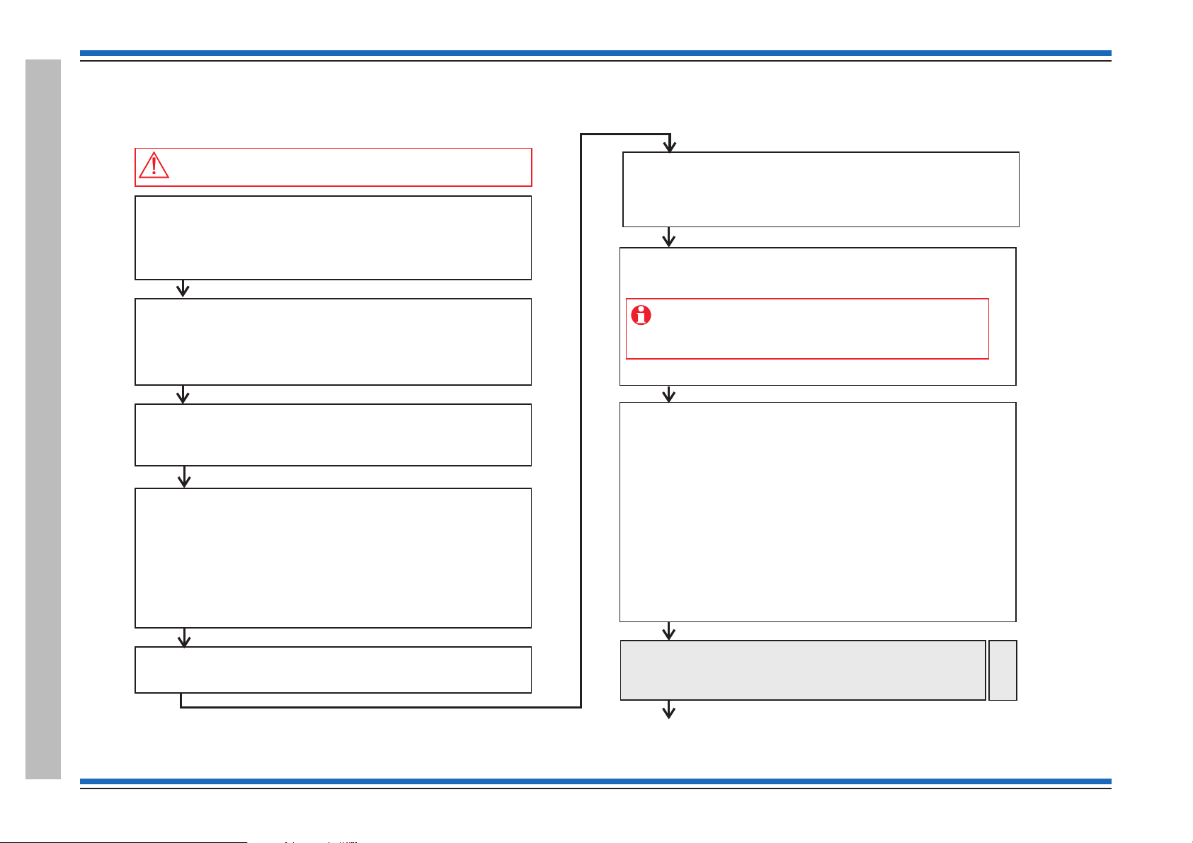
Before powering up the Panel
Open the outer cover and inner cover of the panel and:
– Check all the internal cables within the enclosure are securely fitted
– Ensure no external circuits are connected at this stage, except for
the mains supply which must be connected but not switched ON
–
– Fit the loop card(s) into the required location(s)
Fit the resistors to the master alarm circuits.
– Connect the external printer to the RS232 port, if required.
– Ensure the input - output lines of interface units on the loop are not
connected.
end of line
Inform responsible person(s)
Inform responsible person(s) that the fire alarm system is being
commissioned and occupants in the protected premises will hear
test alarms.
Ensure occupants are made aware of alternative site procedures
should there be a fire event while the system is commissioned.
Pre visit checks
Ensure you have:
shows installed system equipment
Installer will be present to rectify wiring faults
Tools and spare parts are available.
–
–
–
–
As-fitted-drawings that
Access will be available to protected areas having system equipment
Always power-down the panel when.working on the system,
for example when wiring or replacing parts
Survey the installation
Refer to the most recent and ensure that all the fire
system equipment has been installed in accordance with the
installation instructions, respective standards and project specification.
as-fitted-drawings
Power up
– Fit the batteries inside the panel enclosure and connect the battery
leads and then switch ON the mains supply.
Initial tests and set ups
– Carry out a display test and ensure DISPLAY and LEDs are working
– Set the system clock time and date
Configure the RS232 printer port, if an external printer is installed.
– Setup Access levels PIN codes, if required
–
Loop Devices
Configure the links on all LV 4-channel interface units connected to
the loop. Ensure links are set for either Input or Output application.
–
– Power up the mains powered interface unit on the loop.
Ensure all interface Input/Output external wiring remains
disconnected at this stage, unless otherwise instructed. This
action will prevent inadvertent operation of output/plant while
the system is being commissioned.
Loop device address allocation
– Connect only End 1 of a loop circuit and power-up the loop
– Allow address allocation to finish. Any fault(s) on the loop during
allocation must be rectified. Power-down the loop when correcting
loop wiring faults and the power-up to continue address allocation
– Connect only End 2 of the loop circuit and power cycle the loop and
ensure address allocation is complete from End 2.
– Connect both End 1 and End 2 of the loop and check the loop
allocation is complete with both ends of the loop connected.
– ‘Starting Loop n’ displayed after successful allocation of addresses.
– Check all the devices on the loop circuit are installed in their correct
location using the ‘ ’ function at the panel and by referring
to the ‘ ’
– Check to ensure correct devices are installed by viewing the
‘Device status’
– Repeat the allocation process on other loop circuits.
Find Device
as fitted wiring drawings
Continue on next page
Pre-allocate the wireless devices
– If the system has wireless devices then pre-allocate the
wireless devices and bind them to the respective LRT.
Then allocate loop again to allow panel to see the devices.
Radio
Devices
A typical commissioning process
A typical commissioning process
8 4188-856_issue 7_07/15_Generic Vigilon (Compact + VA) Comms.

Installed system test
Put the panel in test mode and then carry out tests in accordance with
the recommendations of BS5839:Part 1 and also in accordance
with project requirements:
– Interface units
Prior to functional test on external equipment connected
to the I/O circuits, ensure the I/O circuits remain isolated.
After functional tests, reconnect the I/O circuits and where appropriate
test the I/O circuits to project recommendations.
S-Cubed - The output volume of an S-Cubed can be adjusted using:
[Set up] ->[Setup]-> [Device]-> [Loop]->[S-Cubed]->[Volume] and then
enter a value between 16 min to 100 max. command at the panel.
Repeat and Mimic panels
Check events are displayed and indicated
carrying out
– Fire sensors
Ensure a device fire causes alarms in the system to sound in
accordance with site specific requirement.
–
–
– Connect Master alarm and Monitored input circuits and move the
end-of-line resistor to the end of each circuit.
– Sounders - Conduct sound level tests to ensure the levels do not fall
below the requirements.
– VAD / Strobe - Check the appropriate S-Quad and S-Cubed devices
provide the visual alarm.
– Messages - Check the correct messages are announced from the
Speakers, S-Cubed and S-Quad devices where installed.
– Remove the Test mode and ensure any disablements are re-enabled.
Procedures for Vigilon Compact VA only
Background music and PA microphone
– Connect and test Background music system
– Connect and test PA microphone
– Test the emergency microphone.
Retrieve the system data to Commissioning tool
Connect the commissioning tool and retrieve the system data,
see Commissioning tools manual.
Devices set up
Ensure all devices on the loop circuits are correctly set up.
– Calibrate speaker circuits on micro DAUs
– Adjust volume of audio at each micro DAU and
Mains Powered DAU.
Audio loop wiring tests
Connect each audio loop and carry out tests to ensure live and
auxiliary messages are outputted to the DAU speaker circuits.
Backup
Back-up the system loop address allocation data to the memory.
Regularly back-up the configuration data during
commissioning, do this every 15 minutes to ensure the
changes made to the configuration is not lost.
Loop wiring tests
Repair
Carry out tests on each loop wiring by introducing open and short
circuit wiring faults. Ensure the panel provides an indication of each
fault. Run the ‘ ’ function at the panel after each wiring fault removal.
From previous page
Configure the system using the Commissioning Tool
Configure the system to site specific requirement using the
Commissioning tool.
Beam Sensor alignment
If there are beam sensors on the loop then commission the beam
sensor pair using the alignment and autogain function at the panel.
Transmit the configured system to the panel
Connect the commissioning tool to the panel and transmit the
system configuration.
Continued on next page
Vigilon 4/6 loops & Compact (VA) panels & network nodes
4188-856_issue 7_07/15_Generic Vigilon (Compact + VA) Comms. 9
A typical commissioning process
Commissioning instructions
Configuration data file
Ensure site file held at the Commissioning tool is the same as the
one held at the panel for future reference and for traceability.
PIN Codes
Change the user PIN code(s) and inform the new codes to the
respective users.
Final changes to configuration
Use the panel menu options to make minor adjustments if required to
the system configuration and then back up the work. All major changes
to the configuration must be done using the Commissioning tool.
From previous page
A typical commissioning process
10 4188-856_issue 7_07/15_Generic Vigilon (Compact + VA) Comms.

Vigilon 4/6 loops & Compact (VA) panels & network nodes
Product Approval and Standards
Fire detection and alarm control panel
The following fire detection and alarm control panels are LPCB approved.
Product number Description Standard
VIG1-24
VIG1-72
COMPACT-24-N
COMPACT-VA EN Vigilon Compact VA 2-loop panel EN 54 Parts 2, 4 & 16. - a Legacy panel
Interface Units
The following interface units are LPCB approved.
Product number Description Standard
S4-34410
S4-34450
S4-34420
S4-34415
S4-34411
S4-34401
S4-34404
S4-34440-02 and
S4-34440-12
EN Vigilon 4-loop panel
EN Vigilon 4/6-loop panel
EN Vigilon Compact 2-loop panel
1 Input interface module (loop powered)
4 Input / output Interface module (loop powered)
1 Output & 1 input (confirmation) interface module (loop powered)
1 Output Interface
Single output interface (loop powered)
Single Channel Mains Switching Interface
Four Channel mains Switching Interface
Mains Powered Interface Units EN54-17: 2005
EN 54 Parts2&4
EN54-17:2005 and
EN54-18:2005
EN54-18: 2005 &
EN54-4:1997 + A1: 2002 + A2: 2006
Manual Call points
The following manual call points are LPCB approved.
Product number Description Standard
S4-34842
S4-34805
S4-34485
S4-34800
4188-856_issue 7_07/15_Generic Vigilon (Compact + VA) Comms. 11
Manual Call Points EN54 Part 11: 2001
EN54 Part 17: 2005
Product Approval and Standards

Commissioning instructions
S-Cubed Mark 3
The following S-Cubed Mark 3 devices are LPCB approved.
Product number Description Standard
Type A Devices
S3-S-R
S3-V-R
S3-S-W
S3-V-W
S3-VAD-HPW-R
S3-VAD-HPR-R
S3-S-VAD-HPW-R
S3-S-VAD-HPR-R
S3-S-VAD-HPW-W
S3-S-VAD-HPR-W
S3-S-VAD-LPR-R
S3-S-VAD-LPW-R
S3-V-VAD-HPW-R
S3-V-VAD-HPR-R
Environmentally protected Devices
S3EP-S-R
S3EP-VAD-HPW-R
S3EP-VAD-HPR-R
S3EP-V-VAD-HPW-R
S3EP-V-VAD-HPR-R
S3 Sounder/Red Body
S3 Voice Sounder/Red Body
S3 Sounder/White Body
S3 Voice Sounder/White Body
S3 VAD/High Perf. White VAD/Red body
S3 High Perf. Red VAD/Red Body
S3 Sounder/High Perf. White VAD/Red Body
S3 Sounder/High Perf. Red VAD/Red Body
S3 Sounder/High Perf. White VAD/White Body
S3 Sounder/High Perf. Red VAD/White Body
S3 Sounder/Standard Perf. Red VAD/Red Body
S3 Sounder/Standard Perf. White VAD/Red Body
S3 Voice Sounder/High Perf. White VAD/Red Body
S3 Voice Sounder/High Perf. Red VAD/Red Body
S3 Sounder/Red Body/EP
S3 VAD/High perform. White VAD/Red Body/EP
S3 VAD/High perform. Red VAD/Red Body/EP
S3 Voice Sounder/High perform. White VAD/Red Body/EP
S3 Voice Sounder/High perform. Red VAD/Red Body/EP
EN54-3 : 2001, A1:2002, A2:2006 (for Sounder)
EN54-23 : 2010 (for Visual Alarm Device VAD)
EN54-17 : 2005 (for Short circuit isolator)
EN54-3 : 2001, A1:2002, A2:2006 (for Sounder)
EN54-23 : 2010 (for Visual Alarm Device VAD)
EN54-17 : 2005 (for Short circuit isolator)
Product Approval and Standards
12 4188-856_issue 7_07/15_Generic Vigilon (Compact + VA) Comms.

Vigilon 4/6 loops & Compact (VA) panels & network nodes
S-Quad Sensors with Visual alarm device (VAD) - introduced post April 2014
The following S-Quad with VAD sensors when operating in the STATES shown in table below are LPCB approved to the respective standard.
Part number Description Standard
S4-711-VAD-HPR S4 Dual Optical & Heat Sensors / Red VAD EN54-5 : 2000, A1 : 2002 (heat)
S4-720-V-VAD-HPR S4 Heat sensor / Voice Sensor Sounder / Red VAD
S4-711-V-VAD-HPR S4 Dual Optical & Heat Sensors / Voice Sounder / Red VAD
S4-911-V-VAD-HPR S4 Dual Optical & Heat & CO Sensors / Voice Sounder / Red VAD
S4-711-VAD-LPW S4 Dual Optical & Heat Sensors / White VAD
S4-711-VAD-HPW S4 Dual Optical & Heat Sensors / White VAD (HP)
S4-711-V-VAD-LPW S4 Dual Optical & Heat Sensors / Voice Sounder / White VAD (Std)
S4-711-V-VAD-HPW S4 Dual Optical & Heat Sensors / Voice Sounder / White VAD (HP)
S4-720-V-VAD-HPW S4 Heat / Voice Sounder / White VAD (HP)
S4-911-V-VAD-HPW S4 Dual Optical & Heat & CO Sensors / Voice Sounder / White VAD HP
Non VAD devices
S4-720 Heat sensor EN54 : Part 5 :2002* - (heat)
S4-715 Optical sensor EN54 : Part 7 : 2000* - (optical smoke)
S4-710 Optical Heat sensors EN54 : Part 7 : 2000* - (optical smoke)
S4-711 Dual Optical & Heat Sensors
S4-711-V S4 Dual Optical & Heat Sensors / Voice Sounder EN54-5 : 2000, A1 : 2002 (heat)
S4-770-S S4 Optical & Heat Sensors / Sounder
S4-771-S S4 Dual Optical & Heat Sensors / Sounder
S4-780-S S4 Heat Sensor Sounder
S4-901 S4 Dual Optical & Heat & CO Sensors
EN54-7 : 2000, A1 : 2002, A2 : 2006 (optical)
EN54-3 : 2001, A1 : 2002, A2 : 2006 (sounder)
EN54-23 : 2010 (visual alarm device VAD)
EN54-17:2005 (short circuit isolator)
EN54-18:2005 (input output devices)
EN54 : Part 5 : 2000* - (heat)
CEA 4021 : 2003-07 Class P heat multisensor detector
EN54-7 : 2000, A1 : 2002, A2 : 2006 (optical)
EN54-3 : 2001, A1 : 2002, A2 : 2006 (sounder)
EN54-17:2005 (short circuit isolator)
EN54-18:2005 (input output devices)
* - these standards are met when the sensor is operating LPCB approved STATES, see STATES table below. Sounder tone description - see next page
"
can be also configured using controls at the main panel.
4188-856_issue 7_07/15_Generic Vigilon (Compact + VA) Comms. 13
If a S-Quad sensor is configured to operate a non LPCB STATE, then this will contravene the LPCB approval. The required STATE is configured during commissioning and
Product Approval and Standards

Commissioning instructions
LPCB approved S-Quad Sensor with VAD device STATES
# - factory default settings
Device
Dual Optical & Heat sensor variant - S4-711
(With VAD) S4-711-VAD-HPR
(With VAD) S4-711-VAD-LPW
(With VAD) S4-711-VAD-HPW
(With Speech) S4-711-V
(With VAD & Speech) S4-711-V-VAD-HPR
(With VAD & Speech) S4-711-V-VAD-HPW
(With Sounder) S4-771-S
Dual Optical, Heat & CO sensor variant- S4-901
(With Speech & VAD) S4-911-V-VAD-HPR
(With Speech & VAD) S4-911-V-VAD-HPW
LPCB approved STATE Meets ~ EN54-7 : 2000, A1:2002, A2:2006
STATE 0 #
STATE 5
STATE 8
STATE 0 #
STATE 9
* EN54-5 : 2000, A1:2002
Medium optical smoke ~ / Class A1 heat *
Medium optical smoke ~ / Class B heat *
Delayed medium optical smoke ~ / Class A1 heat*
Medium optical smoke ~ / Class A1 heat *
Class A1 heat *
Optical & Heat sensor variant - S4-710
(With Sounder) S4-770-S
STATE 0 # Medium optical smoke ~ / Class A1 heat*
Heat sensor variant - S4-720
(With Speech & VAD) S4-720-V-VAD-HPR
(With Speech & VAD) S4-720-V-VAD-HPW
(With Sounder) S4-780-S
Optical sensor - S4-715
STATE 0 #
STATE 5
State 0 # Medium optical smoke
Class A1 heat *
Class B heat *
All S-Quad range of sensor sounder devices meet EN54-17:2005 Input/Output devices plus EN54-18:2005 Short circuit isolation for use on the transmission path of fire detection and alarm systems.
Sounder tone - Meets the following tone settings: High tone ( Continuous 933Hz) & Alternate tone (High 933Hz for 0.25s / low 700Hz for 0.25s)
When an S-Quad sensor is configured to operate a non LPCB approved STATE then this will contravene the LPCB approval.
# - these standards are met when the sensor is operating LPCB approved STATES.
All the LPCB approved STATES applicable to S-Quad fire sensors are shown. The required STATE is configured during commissioning. On initial power-up of the system all the sensors operate in
STATE 0.
Note sensor STATES are not applicable for wireless sensors.
Product Approval and Standards
14 4188-856_issue 7_07/15_Generic Vigilon (Compact + VA) Comms.
Vigilon 4/6 loops & Compact (VA) panels & network nodes
S-Quad Sensors (Legacy product range)
The following S-Quad sensors when operating in the STATES shown in table below are LPCB approved to the respective standard.
Product number Description Standard
S4-720-ST-VO Heat sensor Strobe and Speech (Speech and Strobe - no approval) EN54 : Part 5 :2002* - (heat)
S4-780
S4-780-ST
S4-711-ST Dual Optical & Heat Sensors Strobe (Strobe - no approval) EN54 : Part 7 : 2000* (optical smoke)
S4-911 Dual Optical, Heat & CO Sensors (CO - no approval)
S4-711-ST-VO Dual Optical & Heat Sensors, Speech & strobe (Speech and Strobe - no approval) EN54 : Part 7 : 2000* (optical smoke)
S4-711-VO Dual Optical & Heat Sensors, Speech (Speech - no approval)
S4-771 Dual Optical & Heat Sensors & Sounder
S4-911-ST-VO Dual Optical, Heat & CO Sensors, Speech & Strobe
S4-770 Optical & Heat sensors and Sounder
* - these standards are met when the sensor is operating LPCB approved STATES, see STATES table below. Sounder tone description - see next page
Heat Sensor plus Sounder
Heat Sensor plus Sounder & Strobe (Strobe - no approval)
(Speech, Strobe & CO - no approval)
EN54 : Part 5 : 2002* - (heat)
EN54 : Part 3 : 2001 - (sounder)
EN54 : Part 5 : 2002* (heat)
CEA 4021 : 2003-07 Class P heat multisensor detector
EN54 : Part 5 : 2002* (heat)
EN54 : Part 3 2001 - (sounder tone)
CEA 4021 : 2003-07 Class P heat multisensor detector
"
can be also configured using controls at the main panel.
4188-856_issue 7_07/15_Generic Vigilon (Compact + VA) Comms. 15
If a S-Quad sensor is configured to operate a non LPCB STATE, then this will contravene the LPCB approval. The required STATE is configured during commissioning and
Product Approval and Standards

Commissioning instructions
LPCB approved S-Quad Sensor STATES (Legacy product range)
Meets ~ EN54 : Part 7 :2000
* EN54 : Part 5 :2002
Device
LPCB approved STATE
# - default STATE
Dual Optical & Heat sensor variant -
(With Strobe) S4-711-ST
(With Speech) S4-711-VO
(With Strobe & Speech) S4-711-ST-VO
(With Sounder) S4-771
Dual Optical, Heat & CO sensor variant -
STATE 0 #
STATE 5
STATE 8
STATE 0 #
Medium optical smoke ~ / Class A1 heat *
Medium optical smoke ~ / Class B heat *
Delayed medium optical smoke ~ / Class A1 heat*
Medium optical smoke ~ / Class A1 heat *
S4-911
(With Speech & Strobe) S4-911-ST-VO
STATE 9
Class A1 heat *
Optical & Heat sensor variant -
(With Sounder) S4-770
STATE 0 # Medium optical smoke / Class A1 heat*
Heat sensor variant -
(With Speech & Strobe) S4-720-ST-VO
(With Sounder) S4-780
(With Strobe) S4-780-ST
STATE 0 #
STATE 5
Class A1 heat *
Class B heat *
All S-Quad range of sensor sounder devices meet CEA 4021: 2003-07, where applicable, and meet EN54-17:2005 Input/Output devices plus EN54-18:2005 Short circuit isolation for use on the
transmission path of fire detection and alarm systems.
Sounder tone - Meets the following tone settings: High tone ( Continuous 933Hz) & Alternate tone (High 933Hz for 0.25s / low 700Hz for 0.25s)
When an S-Quad sensor is configured to operate a non LPCB approved STATE then this will contravene the LPCB approval.
# - these standards are met when the sensor is operating LPCB approved STATES.
All the LPCB approved STATES applicable to S-Quad fire sensors are shown. The required STATE is configured during commissioning. On initial power-up of the
system all the sensors operate in STATE 0.
Note sensor STATES are not applicable for wireless sensors.
S-Cubed Mark 2 (Legacy product range)
The Sounders in the following S-Cubed Mark 2 range of products listed below are LPCB approved to EN 54 : Part 3
S3IP-VP-W, S3-VP-W, S3IP-VP-ST-WR, S3-VP-ST-WR, S3IP-VP-R, S3-VP-R, S3IP-VP-ST-RR, S3-VP-ST-RR, S2IP-VP-W, S2IP-VP-R, S3IP-SN-W-V2, S3-SN-W-V2, S3IP-SN-ST-WR-V2,
S3-SN-ST-WR-V2, S3IP-SN-R-V2, S3-SN-R-V2, S3IP-SN-ST-RR-V2, S3-SN-ST-RR-V2, S3IP-SN-ST-RW-V2, S2IP-SN-R-V2 and S2IP-SN-W-V2.
Product Approval and Standards
16 4188-856_issue 7_07/15_Generic Vigilon (Compact + VA) Comms.
Fire Panels
VigilonFireSystem
GENT2015
DesignedtoEN54 Pt 2 & 4
15:45
Fault
SystemFault
Test
Fire
Power
PowerFault
Fault/Dis
Disablement
Previous Next
Delay
Verify
Active
12345678910111213141516
17 18 19 20 21 22 23 24 25 26 27 28 29 30 30 32
Zones
Sounder
FireRoutingO/P
Fault/Dis
Active
FireRoutingO/P
Indicators
Pocket for
Operating instructions
and Log Book
Message display
Access level 1
Controls to scroll events
Key lock for
outer door
Inner door
Printer
Outer door
Access level 2 & 3
Controls
Key lock for
outer door
Indications
Inner door
Operating instructions
and Log Book
Outer door
Message
Display
Access level 1
Controls
to scroll fire
events
Access level 2
Controls
Fault/Dis
Active
FireRoutingO/P
Fault/Dis
Active
FireRoutingO/P
VigilonCompactVoice Alarm System
GENT2010
DesignedtoEN54 Pts 2, 4 & 16
Panelhealthy
15:45
12345678910111213141516
17 18 19 20 21 22 23 24 25 26 27 28 29 30 30 32
Zones
Fault
Disablement
PowerFault
SystemFault
Delay
Test
Fire
Power
Verify
Sounder
CB253
CB254
AllZones
ClearZones
VoiceAlarmZones
SpeakNow
Auxiliarymessages
Emergencymessages
1423 5
6978
10
1
2
3
1
2
3
Previous
Next
ALERT
BOMB
EVACUATE
MIC
TESTSTART
STANDDOWN
TESTEND
byHoneywell
EN54Part2,4&
1
6
COMPACTVOICE
Vigilon
VAActivated
0XXXx
Access level 2 & 3
Controls
Indications
Pocket for
Operating instructions
and Log Book
Message display
Access level 1
Controls to scroll events
Key lock for
outer door
Inner door
Emergency
Microphone
Outer door
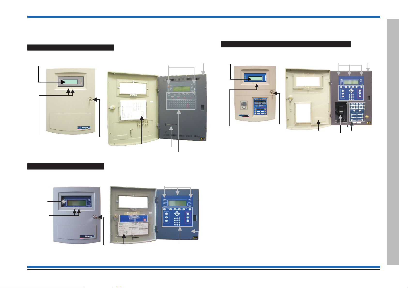
Vigilon 4/6 loop panels (EN/BS)
A BS panel is very similar to an EN panel:
Vigilon 4/6 loops & Compact (VA) panels & network nodes
Vigilon Compact VA panel (EN) (Legacy panel)
Vigilon Compact Panel (EN)
4188-856_issue 7_07/15_Generic Vigilon (Compact + VA) Comms. 17
Fire Panels
Commissioning instructions
Fault
System Fault
Test
Fire
Power
Power Fault
Disablement
Sounder
12345678910111213141516
17 18 19 20 21 22 23 24 25 26 27 28 29 30 30 32
Zones
Previous Next
Delay
Verify
1
23
4
5
6
7
890
"
#
$
%
^
& *
(
+
:
,
-
;
.
)
QW
ER
T
YU I OP
U1
U2
U3
U4
Fire
A
S
DF
GHJ KL
ZXC
VB
NM
Sound Alarms
Silence Alarms
Reset
Cancel Buzzer
Menu On/Off
F4
F3
F1 F2
!
Insert
Delete
SpaceShift
Enter
;
Verify
Panel
buzzer
Vigilon Compact panel or
Vigilon Compact Voice Alarm panel (legacy)
has CB253 / CB254 LEDs in place of Fire routing LEDs
EN Vigilon 4-loop panel or
BS Vigilon 4-loop panel
BS Vigilon 4-loop panel:
Commission
Warning
BS Vigilon 4-loop panel:
NOT USED
Not fitted on
BS Vigilon 4-loop
panel
Previous Next
ABC
DEF
GHI
JKL
MNO
Cancel Buzzer
Menu On/Off
Verify
1 2 3
4 5 6
PQRS
TUV WXYZ
7 8 9
0
Sound Alarms
Silence Alarms
Reset
Enter
THRU
BKSP
0
INS
DEL
F1 F2
F3 F4
U1
U2
12345678910111213141516
17 18 19 20 21 22 23 24 25 26 27 28 29 30 30 32
Zones
Fault
System Fault
Delay
Test
Fire
Power
Power Fault
Verify
Disablement
Sounder
Active
Fault/Dis
Fire Routing O/P
Active
Fault/Dis
Fire Routing O/P
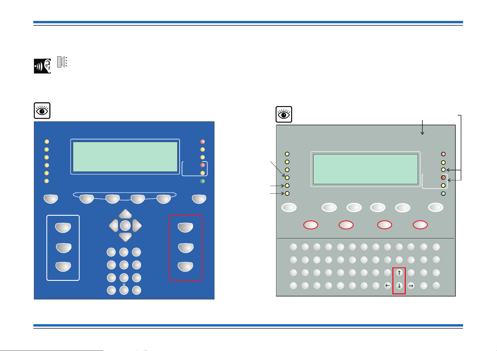
Controls and indications
18 4188-856_issue 7_07/15_Generic Vigilon (Compact + VA) Comms.
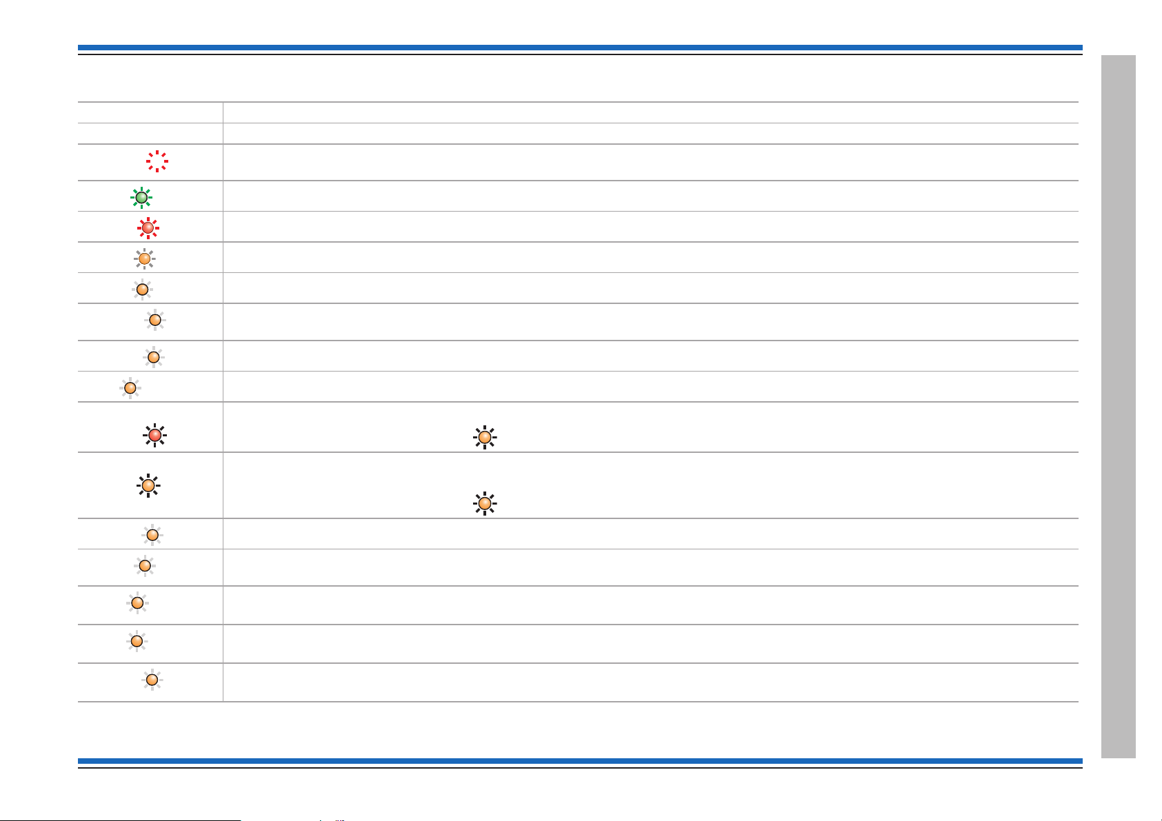
Indications applicable for all Vigilon panels
Zones 1
Power
Fire
Verify
Fault
System Fault
Disablement
Warning
Power Fault
Sounder
Delay
Test
Commission
Indicators Description
Display The Display provides messages of the system status / events by means of 8 lines by 40 characters per line display.
(red)
(green)
(red)
(amber)
(amber)
(amber)
(amber)
(amber)
Fire routing O/P
Hidden-until-lit fire zones indicators. When "Zones" text and number(s) are illuminated it indicates that a FIRE has been detected in the
specific zone(s). (Zone indicators are not applicable for BS Vigilon panels and Network Nodes)
When illuminated it indicates that a supply to the panel is present.
When illuminated it indicates that a FIRE has been detected in the protected premises.
When illuminated it indicates that the Verify button has been pressed and the alarm sounders in the system are delayed from sounding.
When illuminated it indicates that a FAULT has been detected in the fire detection and alarm system or in the audio system.
When illuminated it indicates that a fault has occurred with the system processor. It is important to investigate this fault because the
fire alarm system may not be able to detect fires.
Applicable for EN Vigilon panels only. When illuminated it indicates that a part of the system has been disabled.
Applicable for BS Vigilon panels only. When illuminated it indicates part of the system has been disabled, delayed or not functioning.
Applicable for EN panels only from mid 2015 onwards. When illuminated it indicates the Fire Alarm Routing Equipment is active.
Vigilon 4/6 loops & Compact (VA) panels & network nodes
Active
Fire routing O/P
(red)
Prior to mid 2015 this LED was
CB253 (amber) and it operates with Command Build 253.
Applicable for EN panels only from mid 2015 onwards. When illuminated and steady it indicates the Fire Alarm Routing Equipment is
faulty. When illuminated and flashing it indicates the Fire Alarm Routing Equipment is disabled.
Fault/Dis
4188-856_issue 7_07/15_Generic Vigilon (Compact + VA) Comms. 19
(amber)
(amber)
(amber)
(amber)
(amber)
(amber)
Prior to mid 2015 this LED was
CB254 (amber) and it operates with Command Build 254.
When illuminated it indicates the battery or mains supply to the panel has failed.
Applicable for EN Vigilon panels only. When illuminated (always with either the FAULT light or the DISABLEMENT light) it indicates that
there is a sounder fault (flashing indication) or sounder disablement (steady indication).
Applicable for EN Vigilon panels only
When illuminated it indicates that one or more delay blocks are setup on the panel.
Applicable for EN Vigilon panels only
When illuminated it indicates one or more zones are in Test mode.
Applicable for BS Vigilon panels only
When illuminated it indicates panel is in commissioning mode.
Controls and indications
Commissioning instructions
Menu On/Off
F1 F4
to
Next
Cancel Buzzer
Sound Alarms
Silence Alarms
Reset
Verify
U1
U2
Enter
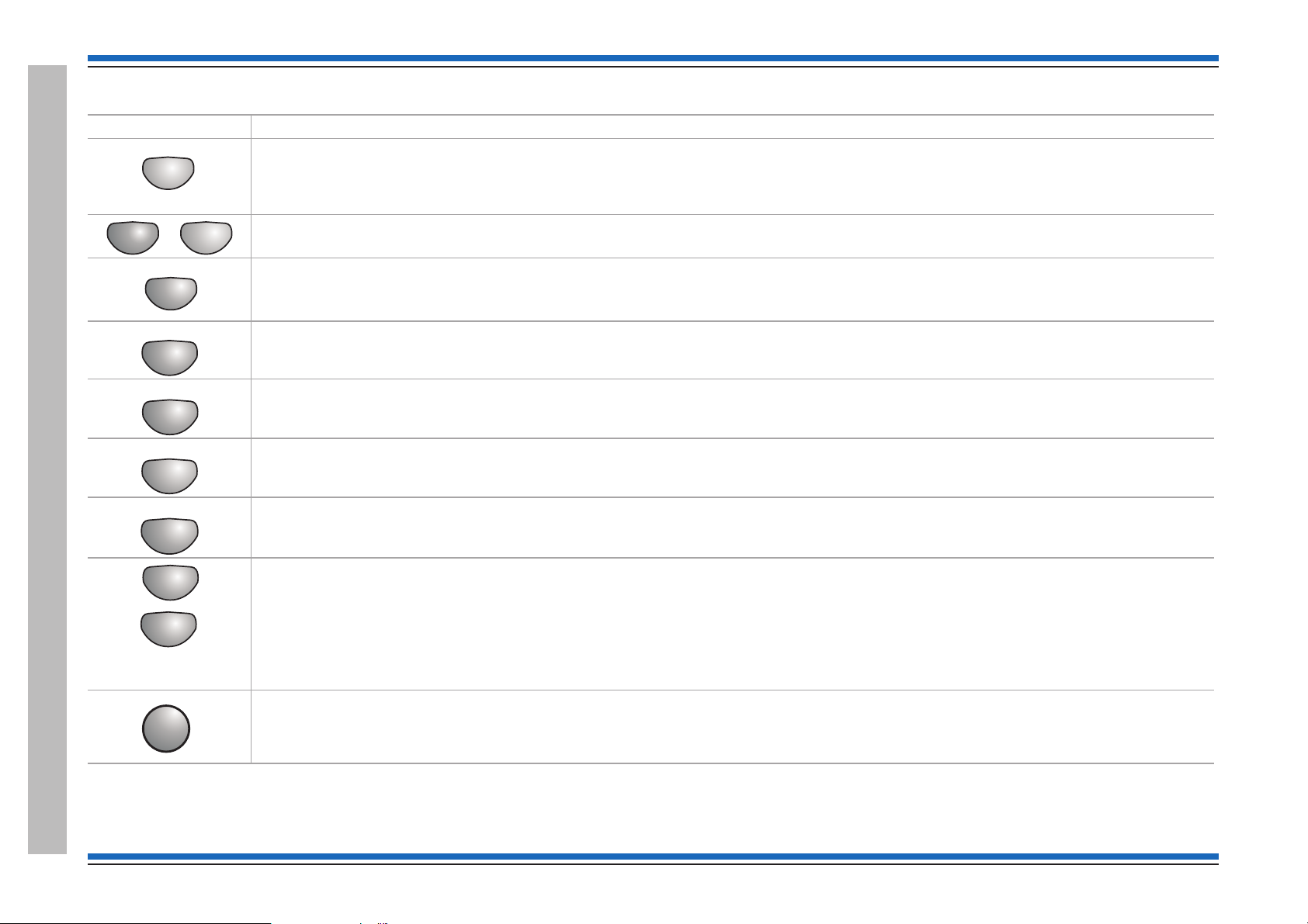
Controls applicable for all Vigilon panels
Controls Description
Pressing Menu On/Off will enable/disable the on screen menu facility which gives access to the system menus.
The 'Fn' buttons are used to select functions and sub-functions of the system menus which appear on the display. Each option available at
a menu level has an associated function button and on pressing a function button will select the option described on the display.
The Cancel Buzzer button when pressed will stop the internal panel buzzer from sounding.
Note the local buzzer is automatically silenced when the emergency microphone is being used to announce live speech from a Vigilon
Compact VA panel.
Pressing the Sound Alarms button will announce 'evacuate message' and sound the evacuate alarms. This button is only pressed in an
emergency or at other agreed times, for example when conducting a system test or practice evacuation.
Pressing the Silence Alarms button will stop emergency message announcements and silence the system alarms.
Pressing the Reset button will clear any fires and return the panel to the condition seen before the fire event. If a fire condition should
reoccur immediately after a 'reset' then the indicated device should be investigated.
Controls and indications
If the Verify facility has been set up, then pressing the 'Verify' button soon after a fire detection will increase the time delay before the alarm
sounders are activated. This gives the user time to investigate the cause of the alarm and option to cancel the alarm within the delay time
period.
The 'U' buttons can be configured during commissioning to output user-defined actions, such as to disable devices in areas where smoke
may be generated and to activate a plant shutdown, for example during a fire condition.
The function of the 'U' buttons should be written on the label that is fitted on the back of the outer door.
Note: The Vigilon 4/6 loop panels have four configurable 'U' buttons.
At a Vigilon panel to operate a 'Un' key: press the 'Shift' key first then the 'Un' key.
This is pressed to acknowledge an entry of data or label text.
20 4188-856_issue 7_07/15_Generic Vigilon (Compact + VA) Comms.
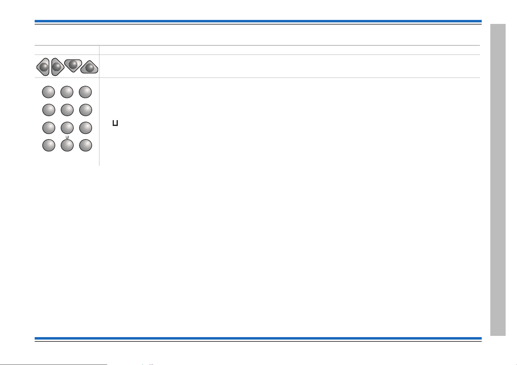
Controls applicable for Vigilon Compact (& VA) panels only:
ABC
DEF
GHI
JKL
MNO
1 2 3
4 5 6
PQRS
TUV WXYZ
7 8 9
0
THRU
BKSP
0
INS
DEL
Controls Description
These four buttons are used to scroll the displayed text.
These buttons allow data to be entered manually at the control panel.
When entering a label each press of a key will scroll the character string, for example:
key 2 will scroll
key 1 will scroll 1?,.;&*/
The bottom row of keys are explained here:
The button is used to enter a SPACE between characters
The INS key allows text to move one position to the right
The DEL key allows a character to be deleted
The BKSP button will delete previous character.
When entering a range data the THRU key is used to represent a '-', for example 1 THRU 5 equals 1-5.
ABC2abc.
Vigilon 4/6 loops & Compact (VA) panels & network nodes
4188-856_issue 7_07/15_Generic Vigilon (Compact + VA) Comms. 21
Controls and indications
Commissioning instructions
n
All Zones
(Green)
Clear Zones
Speak Now
Speak Now
VA Activated
Auxiliary messages
n
(green)
Emergency messages
n
(Red)
All Zones
Clear Zones
Voice Alarm Zones
Speak Now
Auxiliary messages
Emergency messages
1423 5
6978
10
1
2
3
1
2
3
ALERT
BOMB
EVACUATE
TEST START
STAND DOWN
TEST END
VA Activated
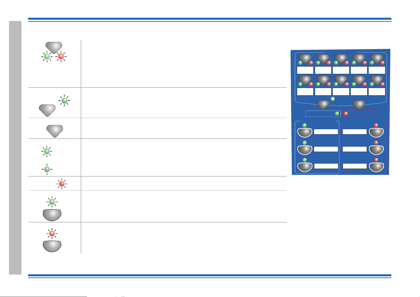
Controls applicable for Vigilon Compact VA panel only - (legacy product)
Pressing one or more of the 10 buttons selects the local Voice Alarm Zone(s) of the local
system to which emergency or auxiliary messages, or emergency microphone is to be
announced. The two LEDs beneath flash alternately to show the Voice Alarm Zone has
(green and red)
(green)
(green)
been selected.
On selecting the required emergency or auxiliary message only one of these LEDs changes
to steady or flashing indication determined by the type of audio to be outputted to the
selected Voice Alarm Zones. The left LED indicates auxiliary message selection while the
right LED indicates emergency message selection.
Pressing the 'All Zones' button allows quick selection of all Voice Alarm Zones
simultaneously. The accompanying LED gives a steady indication when the button is
pressed. Note all the VA Zones that have been setup in your system will give a flashing
indication and those not setup will give no indications.
Pressing 'Clear Zones' button will clear selected Voice Alarm Zones, also when auxiliary
messages are being announced pressing 'Clear Zones' will silence the announcements.
When 'Speak Now' light is illuminated the system is ready to allow live speech
announcement to selected Voice Alarm Zones via the Emergency microphone.
The indicator is lit following the selection of Voice Alarm Zones and on pressing the Press to
Talk (PTT) button on the Emergency microphone.
If the 'Press to Talk' button is released the 'Speak Now' indicator will flash and switch off
after 20seconds duration or immediately switch off on pressing the Clear Zone button.
When the 'VA Activated' LED is illuminated it indicates the voice announcements are being
made or emergency microphone is in use for speech announcement to Voice Alarms Zones.
(red)
When illuminated the system is announcing auxiliary message n to the selected Voice Alarm
Zones.
The indicator is lit following the selection of Voice Alarm Zone(s) and on pressing the
required Auxiliary message button.
Controls and indicationsControls and indicationsControls and indications
Controls and indicationsControls and indications
22 4188-856_issue 7_07/15_Generic Vigilon (Compact + VA) Comms.
When illuminated the system is announcing emergency message n to the selected Voice
Alarm Zones.
The indicator is steady or flashing determined by the type of emergency message being
announced to Voice Alarm Zones.
Vigilon 4/6 loops & Compact (VA) panels & network nodes
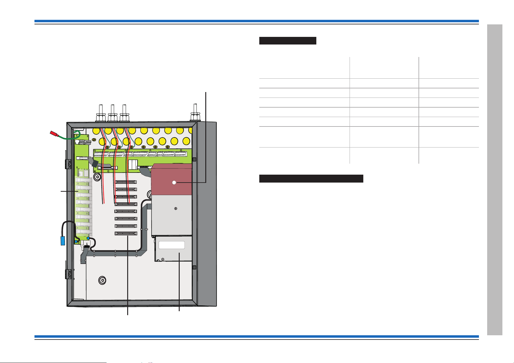
Earth to
inner door
Hinge
points for
inner and
outer doors
PSU
Hinge
points for
inner and
outer doors
Cardboard cover
over PSU
Cables of external circuits
Mains cable
Printer 0V
Transparent
cover over
backplane
Card guides
Vigilon 4/6 loop Panels
These procedures assume the respective 1st fix assembly of the Vigilon 4 loop (VIG1-24) / 6 loop
(VIG1-72) panel is already installed. The 1st fix backbox assembly may be surface or flush
mounted.
The second fix parts must now be installed before powering up the control panel.
¨
Second fix parts
Check that you have the second fix parts, which are supplied with the panel:
¨
Parts
Inner door assembly
Battery Pack (2 x 12V 21Ah)
Battery box
Outer door assembly
Main Control Card
Loop card
EN Vigilon 4 loop
Control panel
(VIG1-24)
11
12
11
11
1
(Option of
up to 4 maximum)
EN Vigilon 6 loop
Control panel
(VIG1-72)
1
1
(option of
up to 6 maximum)
Spares pack (see installation
manual for pack content)
1pack 1pack
Remove the protective covers
¨
Remove the cardboard protection cover fitted over the PSU. The cover is held in by a
retaining clip.
¨
Remove the transparent protection cover fitted over the backplane held together by an
elastic band.
4188-856_issue 7_07/15_Generic Vigilon (Compact + VA) Comms. 23
Vigilon 4/6 loop Panels
Commissioning instructions
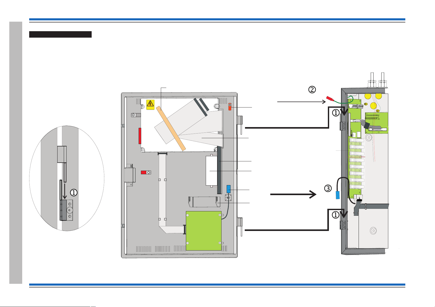
Earth to
inner door
Cables of external circuits
Printer 0V
Transparent
cover over
backplane
WARNING
REMOVAL OF COVER
EXPOSES HIGHVH
VOLTAGES
Transit position of
printer paper roll
and holder pin held
together with an elasticband
Hinge point
Paper roll
holder bracket
Connector for
printer 0V
Earth spade
for connection from
backbox
Inner door
Preformed ribbon
cables held together
under masking tape
to be fitted during
commissioning
Card guide
Danger
Masking tape
BACKBOX (Part view)
Backbox
Inner
door
locating
the hinge pin
Fitting the inner door
Locate the hinge pins on the inner door assembly into the two hinge pin holes j on the backbox outer face.
¨
Fit the earth lead from the backbox to the inner door spade connector k.
¨
Fit together the two blue connectors of the printer 0V leads l, the leads are located at the inner door and backbox intersection.
¨
Vigilon 4/6 loop Panels
24 4188-856_issue 7_07/15_Generic Vigilon (Compact + VA) Comms.

Vigilon 4/6 loops & Compact (VA) panels & network nodes
Fold paper end thus
before attempting to
feed it through printer
Printer
mechanism
Door
Paper
roll
Paper
feed knob
Printer paper roll
"
The printer paper roll is secured with an elastic band to the card guide on the inner door.
Remove the paper roll from the card guide and install paper into the printer mechanism. Ensure the paper roll enters the printer mechanism as shown.
¨
&
On the outside of the inner door there is a paper feed knob, DO NOT turn the knob in an upward direction as this may damage the integral printer.
¨
Upon completion of all commissioning work a new paper roll should be fitted.
4188-856_issue 7_07/15_Generic Vigilon (Compact + VA) Comms. 25
Vigilon 4/6 loop Panels
Commissioning instructions
DKC ASSEMBLY
WARNING
REMOVALOF COVER
EXPOSESHIGHVH
VOLTAGES
Inner door assembly
Danger
RV1
Sound Alarms
Silence Alarms
Reset
Verify
Control buttons
Inner door
1234
17 18 19 20
Zones
With Zone
indicators
(EN)
Display and
keyboard Card (DKC)
Without Zone
indicators
(BS) panel or
Network node
P6
P1
Buttons
enabled
Buttons
disabled
Factory setting
is with link fitted
8
7
6
5
4
3
2
1
ON
SW1
RV1
LCD Contrast adjust
OFF
Clockwise Darker
Anti-Clockwise Lighter
Link is NOT USED
leave link fitted.
It is for special use
with keyswitch
application
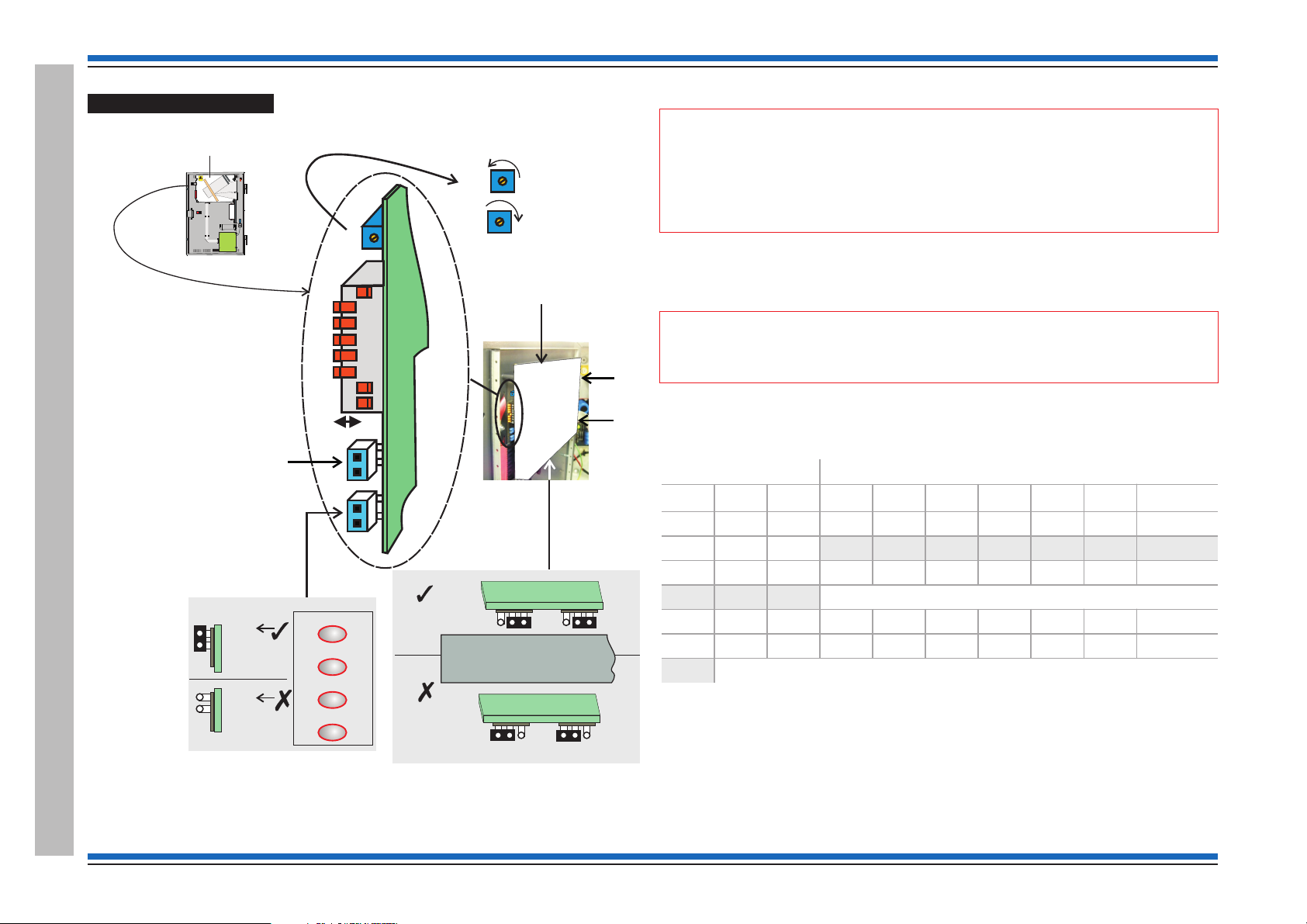
Setting the DKC card
The links, pot and switch on the DKC are factory configured as shown below.
Control buttons
"
The emergency control buttons must always be left in an enabled state, with the 'control
buttons' link fitted.
There is no indication given at the panel when the link is set for inactive controls.
Display Contrast
The display contrast is set using the Pot RV1 on the DAC, which is factory adjusted
¨
for optimum contrast. You can also adjust the contrast using the menu option under
[Test/Eng], see Appendix A menu maps.
"
applicable for some older build of panels.
Domain Address and baud rate settings
Typically the Baud rate set using these switches should be the same as the setting made using the
[TestEng] menu. The baud rate set must be backed up to the NVM. Where a baud rate value that
can only be achieved by [Test/Eng] menu, this must be set using the menu and backed up to NVM.
Baud Rate Domain address
1
Off Off 1200 Off Off Off Off Off Off 64
Off On 2400 Off Off Off Off Off On 1
On Off 9600 Off Off Off Off On Off 2
On On 19200 etc
Zone indicators
The Zone indicators are enabled for normal operation at an EN control panel and must NOT be
disabled.
The contrast adjustment function using the menu options may not be
2 Baud
3
4
5678Address
On On On On On Off 62
On On On On On On 63
Factory set domain address - 1 with 19200 baud (see SHADED cells)
Vigilon 4/6 loop Panels
26 4188-856_issue 7_07/15_Generic Vigilon (Compact + VA) Comms.
The zone indicators are not applicable on a Network node nor on a BS Control panel. On these
products the 'zone indicator' links are set in the 'disable' position.
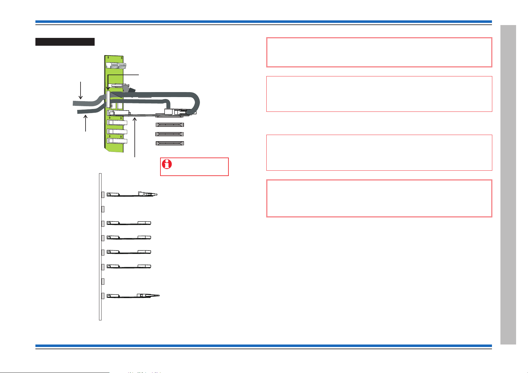
Card installation
Master Controller Card (MCC)
to be fitted to socket
P1 CARD 0 on backplane
Secure the two ribbon
cables (at the fold) under the clamp
located on the backplane
40 way ribbon
20 way ribbon
Card guides
Backplane
Main Controller Card
(SUPPLIED)
Network or IO Card (Optional)
Loop Processor Card (SUPPLIED)
or RS232
Loop Processor Card or RS232
(Option)
Loop Processor Card or RS232
(Option)
Loop Processor Card or RS232
(Option)
Fibre Network or RS232 or
Loop Card#
Network or RS232 or
Loop Card#
# for VIG1-72 only
P1 CARD 0
P2 CARD15
P3 CARD 1
P4 CARD 2
P5 CARD 3
P6 CARD 4
P7 CARD 5
P8 CARD 6
Backplane
Use the USB port on
the MCC to connect to
the Commissioning tool.
Vigilon 4/6 loops & Compact (VA) panels & network nodes
&
When installing cards into the backplane always use anti-static work
procedures. DO NOT use anti-static procedures on live equipment.
"
connect to the Commissioning tool. The DKC now connects directly to the MCC card. The
Commissioning tool connects directly to the USB port on the MCC.
The two ribbon cables held together under a masking tape on the DKC assembly must be routed
into the backbox to connect to the Main Controller Card.
"
backplane. Fit the Main Controller Card (MCC) into the backplane before the ribbon
cables are connected to the MCC.
&
An IO Card is not required for connection to DKC and neither is it required to
Ensure the two ribbon cables from DKC are secured under a clamp on the
Always ensure the panel is completely powered down before removal
or fitting of cards into the backplane. Power down the battery supply before the
mains supply. The power up should be done in reverse order.
¨
Ensure all the cards are installed in their correct location into the backplane and are
firmly seated into their respective slots.
4188-856_issue 7_07/15_Generic Vigilon (Compact + VA) Comms. 27
Vigilon 4/6 loop Panels
Commissioning instructions
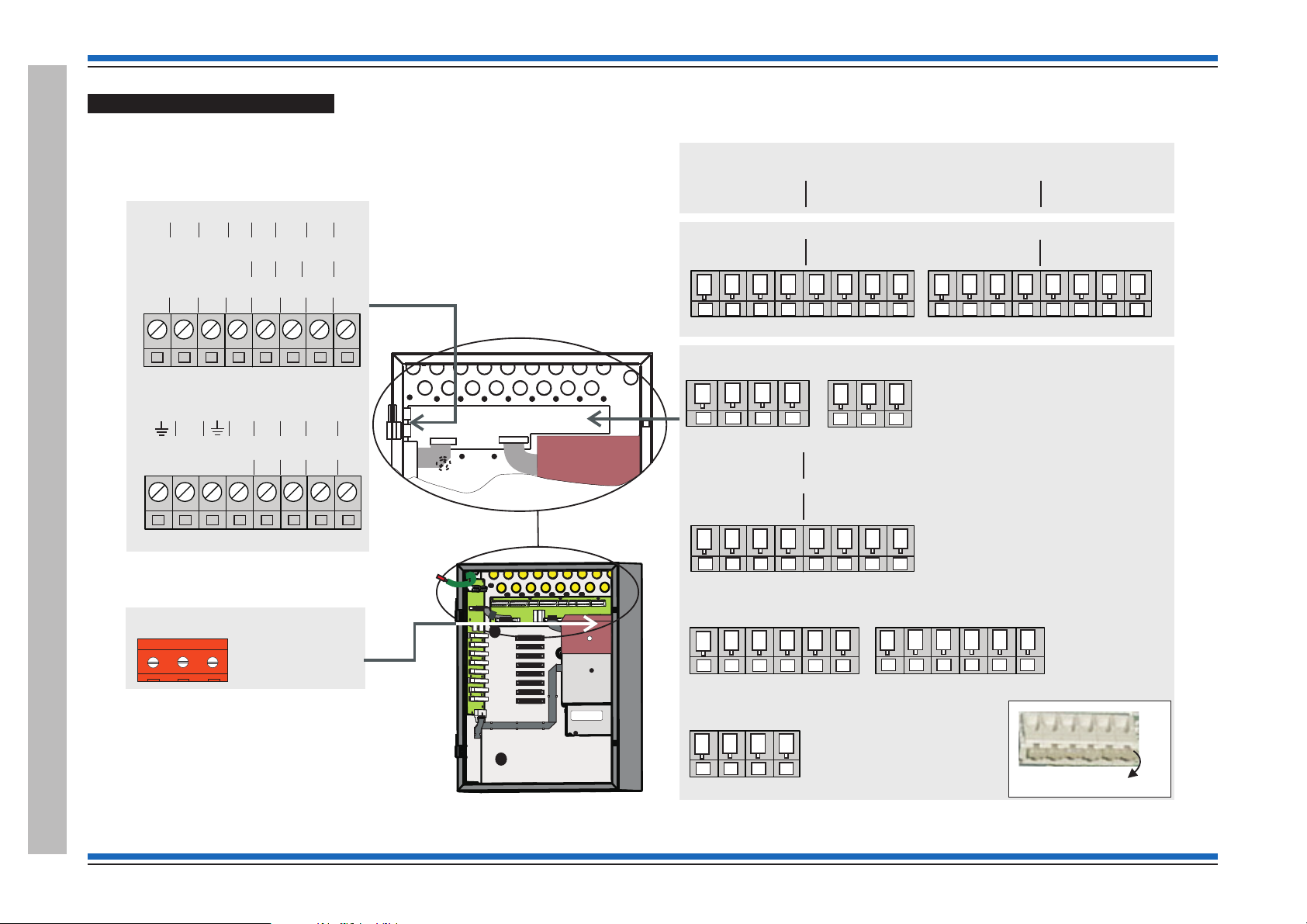
P2
L N
PSU board (located behind the
cardboard cover)
PB1
PB2
Backplane
NETWORK CARD IN SLOT P8
0V1 +VE1 -VE1 0V2 N/C +VE2 -VE2 N/C
LOOP CARD IN SLOT P8 (Loop 6)
L1 0V L2 0V
IO CARD IN SLOT P8
A 5V B 0V CTS Rx RTS TX
IO (RS232) CARD IN SLOT P7
N/C 0V CTS RX RTS TX
LOOP CARD IN SLOT P7 (Loop 5)
L1 0V L2 0V
LOOP 4
L1 0V L2 0V
LOOP 3
L1 0V L2 0V
LOOP 2
L1 0V L2 0V
LOOP 1
L1 0V L2 0V
RS485
A 5VB0V
RS232
TxCTSRxRTS
(WITH IO CARD IN SLOT P2 OF BACKPLANE)
P4
MA1+ MA1- MA2+ MA2-
Master alarm
P5
Clean C
NC C NO
P6
Auxiliary Relay 1
NCCNONCCNO
P7
Auxiliary Relay 2
NCCNONCCNO
P8
RS232 0V
0V 0V 0V 0V
P12
Terminal card
Quick release terminals
P2
P3
0V1 +VE1 -VE1 0V2
N/C N/C +VE2 -VE2
(WITH NETWORK CARD IN SLOT P2 OF BACKPLANE)
CTSRXRTSTX
CARD 4
RS232
CTSRXRTSTX
CARD 3
RS232
CTSRXRTSTX
CARD 2
RS232
CTSRXRTSTX
CARD 1
RS232
Terminals for Network node
These RS232 terminals
are for use with the RS232
wiring associated with IOC
fitted in Card slots 1 to 4.
0V
Terminals for Control panel
Terminals for Control panel and
Network node
Terminals on Terminal Card
Vigilon 4/6 loop Panels
28 4188-856_issue 7_07/15_Generic Vigilon (Compact + VA) Comms.
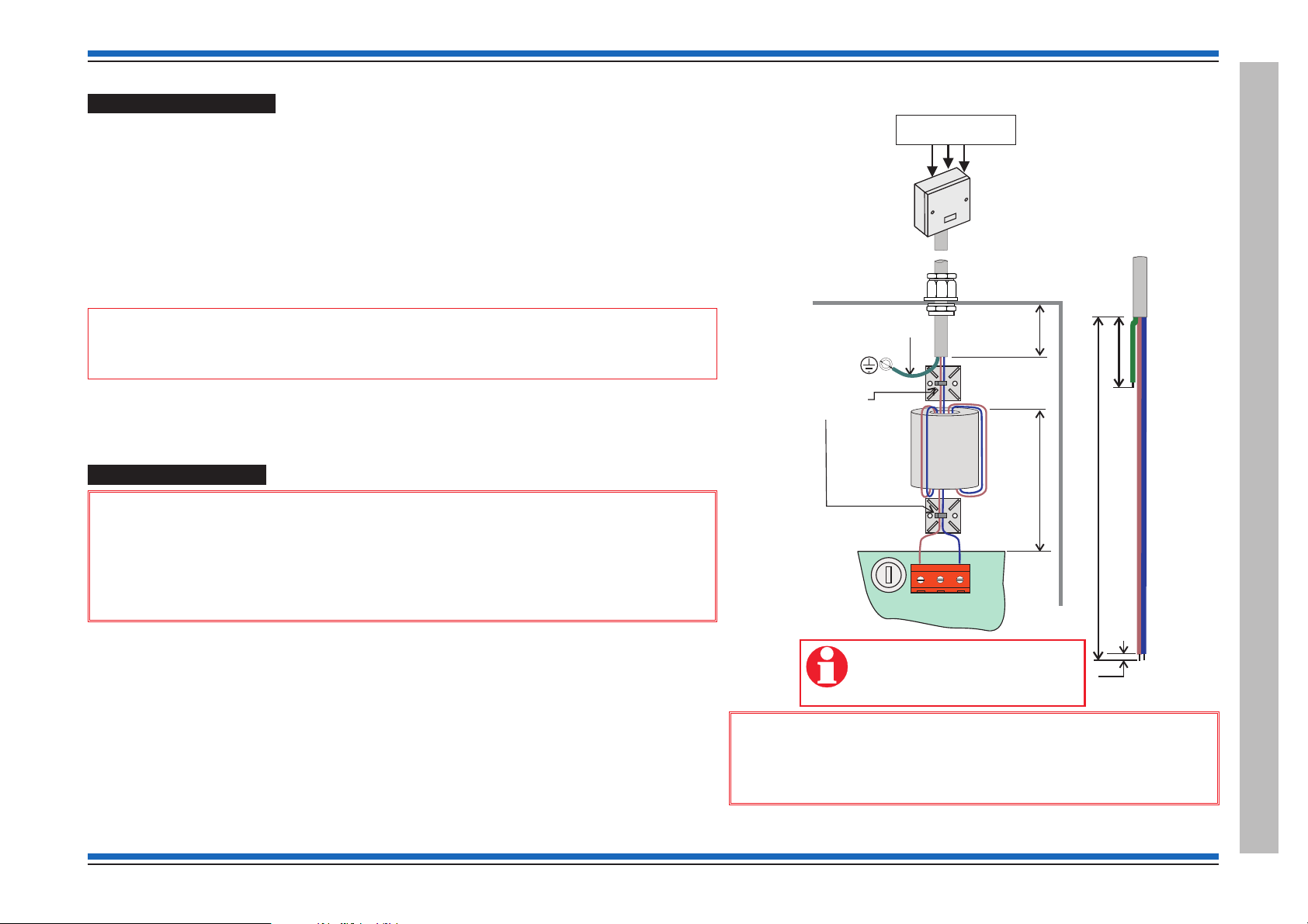
Pre power-up checks
P2
L
N
PSU PCB
The mains cable must be stripped
back to the length shown to allow
live and neutral wires to be wound
through the ferrite core.
Dedicated mains supply
from consumer unit
5A Unswitched
fused spur unit
max. 230V ac
Panel
must be sleeved
Use cable ties
(supplied)
ferrite
core
(supplied)
45mm
35mm
Gland
270mm
50mm
5mm
mains
cable
The mains cable is the only external cable that is required to be connected at this initial stage.
¨
Other external circuit cables are left disconnected, but are connected and tested later, they
include:
all loop circuits
•
clean contacts
•
auxiliary circuits
•
master alarm circuits, has the end-of-line resistors (22K Ohm) fitted to the terminals on the
•
terminal card to inhibit a master alarm circuit fault indication.
and RS232/RS485
•
"
commissioned.
Ensure all cards are securely fitted into their appropriate slots on the backplane.
¨
Ensure all ribbon cables are securely fitted into their respective sockets.
¨
A networked system is commissioned after all the individual standalone systems are fully
Vigilon 4/6 loops & Compact (VA) panels & network nodes
The Mains power is switched on after battery is installed and connected.
¨
Mains supply wiring
&
1. The fire alarm system products are NOT designed to be powered from
IT Power systems.
2. All mains powered equipment must be earthed.
Ensure the mains supply cable enters the equipment via a dedicated cable entry point, which is located
adjacent to the mains terminal block and is also segregated from other loop wiring.
¨
¨
4188-856_issue 7_07/15_Generic Vigilon (Compact + VA) Comms. 29
Mains supply to any fire alarm control and indicating equipment must be via an unswitched 5A
fused spur unit. A disconnect device must be provided to disconnect both poles and must have a
minimum gap of 3mm. The 'disconnect device' should be available as part of the building
installation and must be easily accessible after installation is complete.
The fused spur isolator unit cover should be marked:
FIRE ALARM - DO NOT SWITCH OFF
&
Hazardous voltage remains after operation of a protection
fuse. Take appropriate action to guard against the risk of equipment
having exposed live mains supply.
Vigilon 4/6 loop Panels
Commissioning instructions
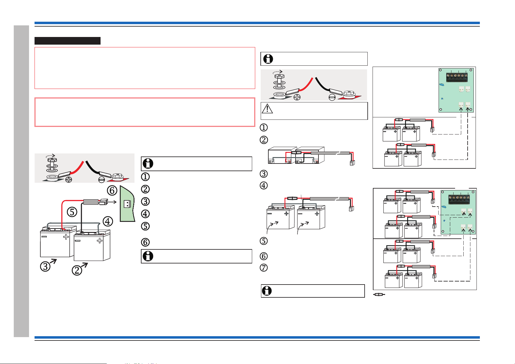
It is recommended that the mains supply to the panel
is switched during battery installation.Off
Fit the bolt, spade connector, washer, spring washer to
each battery terminal, as shown.
Insert the battery on the right into the back box.
Fit the ‘White’ link lead to outer + and - spade connectors
on the two batteries, as shown.
Fit the battery lead assembly (red & black) to the
remaining + and - spade connectors on the two
batteries, observe polarity.
Insert the battery on the left into the back box.
Plug the plug on the battery lead to connector P20 located
on the bottom left of power supply PCB.
The panel will only power up after the mains supply
is switched On.
P20
BT+ BT-
It is recommended that the mains supply to the panel
is switched during battery installation.Off
Fit the bolt, spade connector, washer, spring washer to
each battery terminal, as shown.
Insert the battery on the right into the back box.
Fit the ‘White’ link lead to outer + and - spade connectors
on the two batteries, as shown.
Fit the battery lead assembly (red & black) to the
remaining + and - spade connectors on the two
batteries, observe polarity.
Insert the battery on the left into the back box.
Plug the plug on the battery lead to connector P20 located
on the bottom left of power supply PCB.
The panel will only power up after the mains supply
is switched On.
Red Black
White
Black
Red
TH-
TH+
BT2-
BT2+BT1+
P4
P3
P2
P1
P6
TH1
BT1-
TH-
TH+
BT2-
BT2+BT1+
P4
P3
P2
P1
P6
TH1
BT1-
In-line fuse rated 10A QB ceramic 20mm x 5mm
8 - 12V 21Ah batteries
Battery Box
A
B
Lower
shelf
A
B
Upper
shelf
4 - 12V 21Ah batteries
Battery Box
Upper
shelf
B
A
Lower
shelf
The panel will only power up after the mains supply
is switched .
On
Route the battery red/black lead through hole in the shelf
of the battery box and fit the connector end of the lead
to the PCB, located on the top right side.
Place two more batteries 'B' onto the lower shelf and
repeat procedures to .
jn
Where required, add further four batteries onto the
upper shelf, use procedures to . The only
exception is that the red/black lead is directly connected
to the respective upper connectors on the PCB.
jo
Red
White.
Black
It is recommended that the mains supply is switched
during battery installation.Off
Fit the bolt, spade connector, washer and spring
washer to each battery terminal as shown above.
Place the two batteries on the lower shelf and lay them
horizontally with terminals facing outwards.
Fit the white link lead and then fit the red/black
fused lead to the battery terminals, as shown above.
White.
Red Black
Raise the two batteries to an upright position
and push them back into the enclosure.
Ensure the batteries are held in place while they
are being wired. Ensure the battery terminals
do not come into contact with the metal enclosure.
Black
Red
Battery installation
"
useful life of 5 years or more from the date of manufacture. It is strongly recommended
that batteries are replaced after 4 years of use. All batteries must be disposed of as per
recommendation made by battery manufacturer.
&
an explosion if incorrect batteries are used.
VIG1-24 panel battery installation
Vigilon 4/6 loop Panels
30 4188-856_issue 7_07/15_Generic Vigilon (Compact + VA) Comms.
The panel makes use of sealed lead acid type batteries which can have a
Always use the recommended replacement battery. As there is a risk of
VIG1-72 panel battery installation
 Loading...