

Page 1
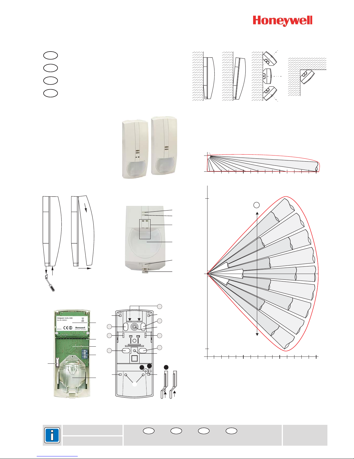
Viewguard Series DUAL
033440 / 033450
Viewguard DUAL AM FAI
033441 / 033451
Viewguard DUAL FAI
Fig. 2
P01715-10-007-00
24.10.2007
GB
E
F
NL
Installation Instructions
Instrucciones de instalación
Notice d'installation
Installatievoorschriften
GB
E
F
Page 2 Página 4 Page 6
NL
Kant 8
Fig. 1
Fig. 3 Fig. 4
Fig. 6
2,5m
5m
10m 15m0m
0°
10°
20°
30°
40°
10°
20°
30°
40°
0m
9m
9m
5m 10m 15m0m
0 (Fig. 5/1)°
A
C
B
D
b
A
B
D
C
a
a
DUAL AM FAI
DUAL FAI
Fig. 5
+/-0°
45°
45°
5/1 5/2 5/3 5/4
a)
b)
c)
Page 2
2 Installation Instructions Viewguard DUAL / AM FAI
1. Introduction
2. Installation Guide line
3. Installation
The Viewguard DUAL motion detector comprises two systems that operate fully
independently: Passive infrared detector plus Microwave detector. The functioning principle
of the detector is based on the intelligent linkage of a passive infrared sensor and
microwave. This type of linking renders the detectors particularly insensitive to air and
thermal turbulences. (Microwave module see Fig. ).
They are delivered with the following main features:
Volumetric mirror optic
, see Fig. , (only 033440/450)
FAI (First Alarm Indication):
Selectable range and sensitivity
Memory function
Selectable range and sensitivity
Self-test (only 033440 )
Monitoring of operating voltage
Tamper and back tamper
Maximum sensitivity is achieved when mounted crosswise to the horizontal detection
zones of the PIR sensors. Therefore, select a mounting site that runs crosswise to the
expected direction of motion. (See Fig. ).
Minimum distance to ceiling: 2 cm
* Mounting above radiators
* Mounting near air discharge openings (e.g. air conditioning systems)
* Direct sunlight
* Mounting near to fluorescent lamps
* Mounting near to light bulbs
(see Fig. 1)
If necessary, break the seal with a small screwdriver or similar object and pull downward
. Press the notch (at the bottom in the middle, see Fig. ) slightly inward and
press off the front of the housing . Lift off the housing front .
• 0° Vertical see Fig. 5/1 Fig.
• Vertical at a 3° downward angle see 5/2 Fig.
• Horizontal at a 45° angle to the left or right see 5/3 Fig.
• Corner mounting see 5/4 Fig.
The detector can be mounted by using the optional swivel bracket (033390 or 033588, see
"Accessories").
(See 4)
For surface mounted wiring
For flush mounted wiring
For use with adjusting hinge
For strain relief with cable strap
3-
(see Fig. 3- , Fig. 6)
2-
Microwave sensor inactive in the "disarmed" state.
When multiple detector on a single zone, Indicate the first detector in alarm
/450
6-A
2-
4Fig. 4Fig. 4Fig. 4-
Fig.
(see Fig. 4)
Required for installation according to DIN CLC/TS 50131-2-4 grade 3.
The backtamper can be used if installed as illustrated in Fig. 5/1, 5/2, 5/3a, 5/3b and 5/4.
Tappet for backtamper. Remove the pin at the tappet, if the backtamper is
being used (see illustration)
Protective cover for back-tamper (on the rear). Remove, when mounting as
per Fig. 5/3a or 5/4
-
-
-
-
-
-
-
-
-
Avoid:
Open housing
Mounting options Screw on position
Cabling, strain relief
A
B, C
C
D
Anti-masking up to 30 cm from the detector
-
Backtamper
a
b
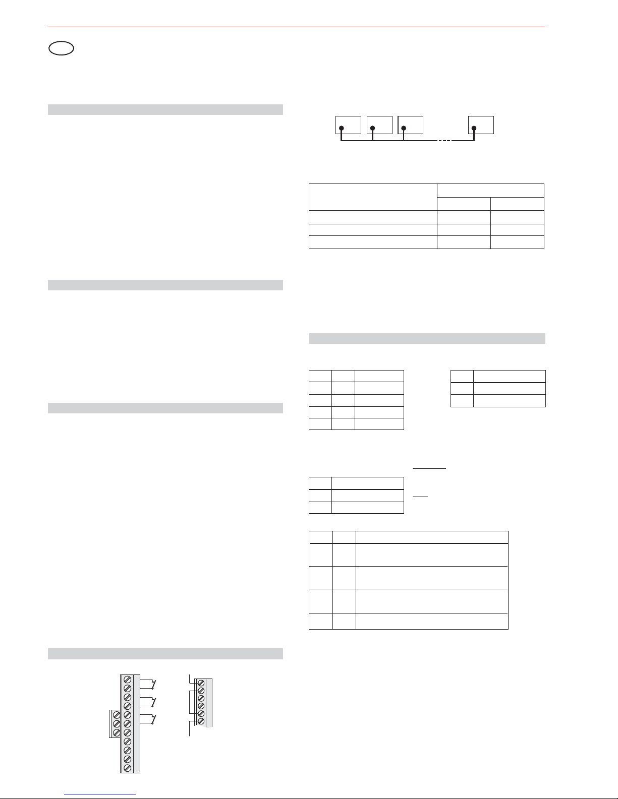
4.2 Easy Logic operating mode without FAI function
The control signals "Walk test", "disarmed" and "FAI" are not connected. In this operating
mode no alarm indication, no FAI function and no memory is available.
The DIP-switches S4, S5 and S6 must be in position "ON".
The Microwave sensor is always active.
Detector 1FDetector 2 Detector 3
Detector 20
F
F
F
Function of inputs:
(Pull-up resistors in the detector)
Function
a) armed
b) disarmed
c) walk test, clear alarm indication
High
Low
Inputs
walk test "T" arm/disarm "U"
High
High
Low
Low
4.1 Viewguard operating mode with FAI function
(FAI = irst larm ndication)
The FAI connections "F" of all detectors are connected to one another. A connection to the
control panel is not required. The LED flashes on the detector that triggers first, the LED
light on the subsequently triggered detectors (see 6. "LED indication").
FA I
FAI logic:
Close housing
Apply operating voltage
Walk test in Easy Logic mode
See Fig. 1 in reverse order. Ensure that the housing is closed correctly and locked into
position. Do not insert the seal to lock the housing until installation is completed
After applying the operating voltage, the detector automatically performs an initialisation.
Both LEDs flash (see 6.). . After max.
60 seconds the detector is ready for operation. After this period, do not change anything in
the close vicinity (up to 50 cm) that may influence the reflected light.
The detector is automatically in for approx. after initialising is
completed. Conduct the walk test within this time period. LED indication see 6.
The detector is operationally ready after the 10 minutes have expired.
Do not enter the Anti-Mask range during initialisation
walk test mode 10 minutes
5. Setting
DIP-switches: see Fig. 3-
S3 Sensitivity
ON normal
OFF high
S1 S2 Range
OFF OFF 8 m
ON OFF 11 m
OFF ON 13 m
ON ON 15 m
S4 S6 Operating mode ()Anti-Mask only 033440/
ON ON Easy Logic mode only (see 4.2)
ON OFF Viewguard mode with FAI
OFF OFF Viewguard mode with FAI
OFF ON
450
Anti-Mask always active
Anti-Mask always active
Anti-Mask inactive in "armed" state
N.A.
S5 Fault/Cover
ON do not save
OFF save
Memory:
Do not save:
Save:
Fault/cover signal is automatically cleared after
elimination of the fault/cover.
Not possible in Easy Logic mode!
Fault/cover signal remains saved in the detector
until it is cleared via control panel.
4. Connection diagram
Installation Instructions
Viewguard Series DUAL
GB
Fault Tamper Alarm T U F
+
Fault
Alarm
Tamper
Walk test
0V
+12VDC
Spare terminals for
end of line resistors
arm/disarm
FAI
Fault Tamper Alarm
If thecontrolpanel hasno fault input,
the "Alarm" and "Fault" outputs can
be connectedin series.
PIR and MW operate automatically
with the same range.
Page 3

3
Installation Instructions Viewguard DUAL / AM FAI
7. Technical specification
Operating voltage Vnom 12 V DC
Operating voltge range 8.0 V to 15 V DC
Current consumption at Vnom=12 V DC 6.6 mA
Range (programmable): 8 / 11 / 13 / 15 m
PIR and MW together
PIR sensor temperature-compensated
PIR sensitivity (programmable): normal / high
(only 033440/450) up to 30 cm
Frequency microwave:
- 033440 / 033441 9.35 GHz (X band)
- 033450 / 033451 10.587 GHz (X band)
Installation position vertical, optics at bottom
Alarm contact:
- Contact rating 15 V DC / 0.1 A
- Internal resistance 25
- Contact position open in the event of alarm
Fault contact:
- Contact rating 15 V DC / 0.1 A
- Internal resistance 25
- Contact position open in the event of fault
Tamper contact:
- Contact rating 15 V DC / 0.1 A
- Internal resistance 10
- Contact position open in the event of tamper
Protection category as per EN 60529 IP 30
Environmental class as per VdS II
Operating temperature range -10 °C to +55 °C
Storage temperature range -25 °C to +70 °C
DimensionsWxHxD 64x158x48mm
Colour White
(similar to RAL 9010)
Anti-Mask function
£W
£W
£W
8. Accessories
033390 Adjustable joint
033588 Ball-and-socket set for wall and corner mounting
033391 Seal
Swivel range: Horizontal
Vertical +4° up to -8°
(PU = 20 piece)
±20°
033440 / 033450 Viewguard DUAL AM FAI DIN CLC/TS 50131-2-4 grade 3
033441 / 033451 Viewguard DUAL FAI DIN CLC/TS 50131-2-4 grade 2
The detectors Viewguard DUAL AM FAI, Item no. 033440 / 033450 and Viewguard DUAL
FAI, Item no. 033441 / 033451 when used as intended, comply with the basic requirements of Article 3 of the R&TTE
The EUconformity declarationcan be downloadedat
"www.honeywell.com/security/de"under Service-/ Download.
The devicesmay onlybe sold andoperated inthe following countries:
Germany, Austria, Switzerland, Liechtenstein, Poland, Slovakia, Czech Republic,
Luxembourg,Turkey,Greece, Latvia,Lithuania, Hungary, Belgiumand Netherlands.
France, Spain,Italy,Portugal andUnited Kingdom.
9. EU conformity
033440 /033441:
033450 /033451:
6. LED indication
on
flashing
blanked
1)
No LED indication in Easy Logic mode
2)
See table in Chapter 4.1 "Function of inputs", function c).
Operating Mode Red Yellow What Indication reset
Start up When power on After 30 sec.
Walk test Motion detected
Covering detected
Failed self test
After disarming First alarm Clear signal from control panel
with preceding
alarm Subsequent alarm
Normal operation
Automatically without motion
When covering is removed
When fault is eliminated
Clear signal from control panel
1)
2)
2)
Subject to change without notice
LED yellow: see Fig. 2LED red: see Fig. 2-
Page 4
4 Instrucciones de instalación Viewguard DUAL / AM FAI
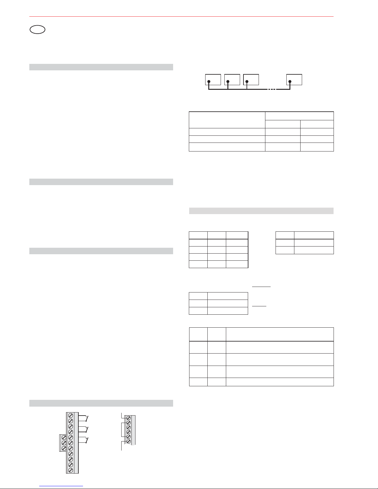
4.2 Modo de funcionamiento Easy Logic sin función FAI
Las señales de control "Test de paseo", "Desarmado" y "FAI" no están conectadas. En este
modo de funcionamiento no hay disponibles indicaciones de alarma, ni función FAI, ni
memoria.
Los interruptoresDIP S4,S5 yS6 hande estaren posición”ON”.
El sensorde microondassiempre está activo.
4.1 Modo de funcionamiento de Viewguard con función FAI
(FAI= irst larm ndication -indicación deprimera alarma)FA I
Lógica FAI:
Las salidas"F" detodos los detectoresdeben estar conectadas entresí. No es necesariauna
conexión con el panel de control. El LED parpadea en el detector que se activa primero, y
permanece fijo en los detectores activados posteriormente (véase el punto 6. "Indicación
LED").
Instrucciones de instalación
Viewguard Serie DUAL
5. Ajuste
Interruptores DIP:véase lailustración 3-
Detector 1FDetector 2 Detector 3
Detector 20
F
F
F
Función para entradas:
(Resistencias pull-up en el detector)
Función
a) Armado
b) Desarmado
c) , indicación alarma claraTest de paseo
Alto
Bajo
Entradas
Test de paseo"T"
Alto
Alto
Bajo
Bajo
No guardar:
Guardar:
La señal de fallo/enmascaramiento se borra
automáti-camente después de la eliminación del
fallo/enmascaramiento.
La señal de fallo/enmascaramiento permanece
guardada en el detector hasta que se borra mediante
el panelde control.
¡No posibleen modoEasy Logic!
Memoria:
S5 Fallo/enmascaramiento
ACT no guardar
DESACT guardar
S3 Sensibilidad
ACT normal
DESACT Alto
S1 S2 Alcance
DESACT DESACT 8 m
ACT DESACT 11 m
DESACT ACT 13 m
ACT ACT 15 m
Cerrar carcasa
Aplicar tensión de trabajo
Testde paseo enmodo Easy Logic
Véase lailust. 1en orden inverso.Asegúrese de quela carcasaestá cerradacorrectamente y
bloqueada en posición. No introduzca el sello para bloquear la carcasa hasta que no haya
finalizado lainstalación
Después de aplicar la tensión de trabajo, el detector realiza automáticamente una
inicialización.Ambos LEDs parpadean(véase 6.).
. Despuésde untiempo
máximo de 60 segundos, el detector está listo para funcionar. Después de este periodo no
cambie nadaen lasproximidades (hasta 50cm) quepueda influir sobrela luzreflejada.
El detector está en modo de test de paseo durante unos 10 minutos una vez finalizada la
inicialización. Realice el test de paseo dentro de este intervalo de tiempo. Indicación LED,
véase elpunto 6.
No introduzcael modoanti-enmascaramiento durantela inicialización
4. Diagrama de conexiones
E
Fault Tamper Alarm
Si el panel de control no tiene
ninguna entradas de fallo, las
salidas "Alarma" y "Fallo" pueden
conectarse en serie.
Fallo
Alarma
Tamper
Test de paseo
0V
+12VDC
Terminales de
repuesto para
resistencias de
final de línea
Armar/desarmar
FAI
Fault Tamper Alarm T U F
+
1. Introducción
2. Instrucciones de montaje
3. Instalación
El detector de movimiento DUAL Viewguard comprende dos sistemas que funcionan de
forma totalmente independiente: Detector pasivo de infrarrojos más detector de
microondas. El principio de funcionamiento del detector se basa en la conexión inteligente
de un sensor de infrarrojos pasivo y microondas. Este tipo de conexión hace que los
detectores sean especialmente insensibles a las turbulencias de aire y térmicas. (Módulo
de microondas, véase la ilust. 3-
.
Dispone de las siguientes características principales:
Óptica deespejo enabanico (véase lailustración. 3- , ilustración.6)
, véasela ilust.2- , (sólo 033440/450)
El sensorde microondaspuede desactivarse enel estado“desarmado”.
FAI(indicación de primeraalarma):
Cuando existen múltiples detectores en una zona única, indica el primer detector en
alarma
Alcance ysensibilidad seleccionables
Función dememoria
Alcance ysensibilidad seleccionables
Supervisión dela tensiónde funcionamiento
Autotest (sólo033440/450)
Tamper decarcasa ypared
La sensibilidad máximase alcanza cuandose monta de formacruzada respecto alas zonas
de detecciónhorizontales de lossensores PIR. Portanto, seleccione unlugar demontaje que
atraviese ladirección esperadade movimiento. (Véasela ilust.6-A).
Distancia mínimarespecto altecho: 2 cm
* Montaje porencima deradiadores
* Montaje cercade salidasde aire(p.ej., sistemasde aireacondicionado)
* Luz solardirecta
* Montaje cercade lámparasfluorescentes
* Montaje cercade bombillas
(véase la ilust. 1)
En caso necesario,rompa el sello conun pequeño destornillador uobjeto similar y tirehacia
abajo .Apriete la muesca(en el fondoen la parte central, véasela ilust.2- ) ligeramente
hacia adentro extraiga la parte frontal de la carcasa . Levante la parte frontal de la
carcasa .
• 0° vertical Ilust. 5/1 Ilust. 4-
• Vertical en un ángulo descendente de 3° Ilust. 5/2 Ilust. 4-
• Horizontal en unángulo de 45° hacia laderecha o la izquierda Ilust. 5/3 Ilust. 4-
• Montaje en esquina Ilust. 5/4 Ilust. 4El detectorpuede montarse utilizandola rótula demontaje opcional (033390ó 033588, véase
”Accesorios”).
(véase lailust. 4)
Para un cableado montado en superficie
Para un cableado montado empotrado
Para la utilización con charnela de ajuste
Para descarga de presión con brida en el cable
(véase la ilust. 4)
Necesario parala instalaciónconforme a laCLC/TS 50131-2-4Grado 3.
El tamperde paredutilizarse si seinstala comose indica enla ilust.5/1, 5/2, 5/3a,5/3b y5/4.
Empujador para tamper trasero. Quite la clavija en el empujador si se está
usando eltamper trasero(véase la ilustración)
Cubierta protectora para tamper trasero (en la parte posterior). Quitar, cuando
se montasegún lailust. 5/3a o5/4
-
-
-
-
-
-
-
-
-
-
Evite:
Abrir carcasa
Opciones de montaje Tornillo en posición
Cableado
A
B, C
C
D
Tamper de pared
a
b
Anti-enmascaramiento hastaa 30cm del detector
PIR y MW funcionan automáticamente
con el mismo alcance.
Armar/desarmar "U"
S4 S6 Modo de funcionamiento
(a )
DESACT ACT No permitido
nti-enmascaramiento sólo 033440/450
enmascaramiento
enmascaramiento
enmascaramiento
ACT ACT Modo Easy Logic sólo (véase 4.2)
ACT DESACT Modo Viewguard con FAI
DESACT DESACT ModoViewguard con FAI
Anti- siempre activo
Anti- siempre activo
Anti- inactivo en estado “armado”
Page 5

5
Instrucciones de instalación Viewguard DUAL / AM FAI
6. Indicación LED
act
parpadeando
en blanco
1)
Ninguna indicación LED en modo Easy Logic
2)
Véase la tabla del capítulo 4.1 "Función de las entradas", función c).
7. Especificación técnica
Voltaje de trabajo Vnom 12 V DC
Rango de voltaje de trabajo 8,0 V a 15 V DC
Consumo de corriente a Vnom=12 V DC 6,6 mA
Alcance (programable) 8 / 11 / 13 / 15 m
PIR y MW juntos
Sensor PIR Con compensación de temperatura
Sensibilidad PIR (programable): normal / alta
(sólo 033440/450) hasta 30cm
Frecuencia microondas:
- 033440 / 033441 9,35 GHz (banda X)
- 033450 / 033451 10,587 GHz (banda X)
Posición de instalación vertical, óptica en el fondo
Relé de alarma:
- Clase de contacto 15 V DC / 0,1 A
- Resistencia interna 25
- Posición de contacto abierto en caso de alarma
Relé de fallo:
- Clase de contacto 15 V DC / 0,1 A
- Resistencia interna 25
- Posición de contacto abierto en caso de fallo
Relé de tamper
- Clase de contacto 15 V DC / 0,1 A
- Resistencia interna 10
- Posición de contacto abierto en caso de sabotaje
Categoría de protección según la EN 60529 IP 30
Clase medioambiental según VdS II
Rango de temp. de funcionamiento -10 °C a +55 °C
Rango de temp. de almacenamiento -25 °C a +70 °C
Dimensiones An x Al x Pr 64 x 158 x 48 mm
Color Blanco
(similar a RAL 9010)
Función anti-
enmascaramiento
£W
£W
£W
8. Accesorios
9. Conformidad CE
033390
033588 Juegode rótulas para montaje en pared y esquina
033391 Sello
Rótula de montaje
Alcance de giro: Horizontal ±20°
Vertical +4° hasta -8°
(PU = 20 unidades)
La declaraciónde conformidadUE puede descargarseen
033440 / 033450 Viewguard DUAL AM FAI CLC/TS 50131-2-4 Grado 3
033441 / 033451 Viewguard DUAL FAI CLC/TS 50131-2-4 Grado 2
Los detectores Viewguard DUALAM FAI,nº art. 033440 / 033450y Viewguard DUAL FAI, nº
art. 033441 / 033451 cuando se utilizan según las especificaciones, cumplen con las
exigencias básicasdel art.3 de ladirectriz R&TTE1999/5/EU.
"www.honeywell.com/security/de",Service-/ Download.
Los dispositivossólo puedenvenderse y operarseen lossiguientes países:
Alemania, Austria, Suiza, Liechtenstein, Polonia, Eslovaquia, República Checa,
Luxemburgo, Turquía, Grecia, Letonia, Lituania, Hungría, Bélgica y Países Bajos.
Francia, España, Italia, Portugal y United Kingdom.
033440 /033441:
033450 / 033451:
Sujeto a cambios sin previo aviso
LED amarillo:
LED rojo:
véase lailustración
véase lailustración 2-
2-
Modo funcionamiento Rojo Amarillo Qué Rest. indicación
Inicio Si encendido act. Después de 30 s
detectado Cuando se quita
Autotest fallido Cuando se elimina el fallo
Después del des- Primera alarma Señal clara del panel de control
arme con alarma
precedente Alarma posterior Señal clara del panel de control
Funcionamiento normal
Test de paseo Movimiento detectado Automáticamente sin movimiento
Enmascaramiento el obstáculo
1)
2)
2)
Page 6

6
4.2 Mode de fonctionnement Easy Logic sans fonction FAI
Les entrées de commande 'Mode test', Désactivé et 'FAI' ne sont pas connectées. Dans ce
mode de fonctionnement, l'indication d'alarme, la fonction FAI et la mémoire ne sont pas
disponibles.
La détectionhyperfréquence
Les commutateursS4, S5et S6 doiventêtre enposition 'ON'.
est toujoursactivée.
4.1 Mode de fonctionnement Viewguard avec fonction FAI
FA I
Logique FAI :
(FAI= irst larm ndication -Indication depremière alarme)
Les connecteursFAI, 'F', de tousles détecteurssont raccordés entreeux. Aucune connexion
à la centrale n'est requise. La LED du détecteur qui se déclenche en premier clignotera. La
LED des détecteursqui se déclenchent parla suite, s'allumeraen fixe (consulterla section 6.
'Indications fourniespar lesLEDs').
Fermeture du boîtier
Mise sous tension
Mode test en mode EasyLogic
Appliquer la procédure inverse de celle détaillée en figure 1. S'assurer que le boîtier soit
correctement fermé et verrouillé en position. Ne pas insérer le scellé dans leboîtier tant que
l'installation n'estpas terminée.
Ala misesous tension,le détecteurs'initialise automatiquement.Les deuxLEDs clignotent (cf.
6). . Au bout de 60 secondes
maximum, le détecteur est prêt. Une fois ce délai écoulé, ne rien changer dans le voisinage
immédiat dudétecteur (jusqu'à50 cm) aurisque d'influencerla lumière réfléchie.
Une fois l'initialisation terminée, le détecteurpasse automatiquement en pendant
environ . Effectuer le test de la zone de couverture pendant ce délai. Pour les
indications fourniespar lesLEDs, consulter lasection 6.
Ne pas régler la portée de l' anti-masque pendant l'initialisation
mode test
10 minutes
4. Schéma de câblage
Notice d'installation
Détecteurs de mouvement
Viewguard Dual
Notice d'installation Viewguard Dual / AM FAI
F
Détecteur 1FDétecteur 2 Détecteur 3
Détecteur 20
F
F
F
Fonction des entrées :
-(Résistances pull up dans le détecteur)
Fonction
a) activé
b) désactivé
c) mode test, effacementde la mémoired'alarme
Entrées
Mode test 'T'
Activier/Désactiver 'U'
Haut
Haut
Bas Bas
Haut
Bas
5. Configuration
Commutateurs : voir Fig. 3-
å
S3 Sensibilité
ON Normale
OFF Élevée
S1 S2 Portée
OFF OFF 8 m
ON OFF 11m
OFF ON 13 m
ON ON 15m
S5 Défaut/masquage
ON Ne pas sauvegarder
OFF Sauvegarder
Mémoire :
S4 S6 Mode de fonctionnement
()
ON ON Mode Easy Logic uniquement (cf. 4.2)
ON OFF Mode Viewguard avec FAI
OFF OFF Mode Viewguard avec FAI
anti-masque, 033440 uniquement
Anti-masque toujours actif
Anti-masque toujours actif
Anti-masque inactif en état 'armé’
/450
OFF ON n.a.
Ne passauvegarder:
Sauvegarder:
L'information de défaut/masquage est automatiquement effacée aprèssuppresion dudéfaut/masquage.
Impossible en mode Easy Logic !
L'information de défaut/masquage est enregistrée
dans le détecteur jusqu'à ce quelle soit effacée par
la centrale d'alarme.
1.
2.
3.
Introduction
Consignes d'installation
Installation
Le détecteur de mouvement Viewguard DUAL combine deux technologies qui fonctionnent
indépendemment: la détection infrarouge passif et la détection hyperfréquence. Le principe
de fonctionnement du détecteur repose sur la liaison intelligente entre la détection
infrarouge passif et la détection hyperfréquence. Ce type de liaison garantit l'insensibilité
des détecteurs aux mouvements d'air et aux variations de température (module à hyper-
fréquence, voir Fig. 3- ).
Ces derniers présentent les caractéristiques suivantes :
Optique à miroir (cf. fig. 3- , fig. 6)
, cf. fig. 2- , (033440/450 uniquement)
La détection à hyperfréquences peut être désactivée en mode 'Désactiver'
FAI (First Alarm Indication - Indication du premier détecteur en situation d'alarme
lorsque plusieurs détecteurs sont installés dans la même zone)
Fonction mémoire
Portée et sensibilité sélectionnables
Autotest (033440/450 uniquement)
- Supervision de la tension d'alimentation
Auto protection à l'ouverture et à l'arrachement
La sensibilité optimale est obtenue lorsque l'emplacement du détecteur impose un sens du
mouvement de l'intrus tel qu'indiqué sur la figure 6-A.
Distance minimaleau plafond: 2 cm
Aéviter:
* Montage au-dessusde radiateurs
* Montage prèsd'évacuations d'air(systèmes declimatisation, parexemple)
* la lumièredirecte
* Montage àproximité delampes fluorescentes
* Montage àproximité delampes àincandescence
(cf. fig. 1)
Si nécessaire,enlever le scelléau moyend'un tournevis oude tout autreobjet similaireet tirer
vers le bas . Appuyer légèrement sur la languette (située sur la partie inférieure du
détecteur,cf fig 2- ) et fairepivoter la faceavant Séparer laface avantde l'embase
du détecteur .
• Vertical 0° Voir fig. 5/1 Fig. 4-
• Vertical avec un angle plongeant de 3° Voir fig. 5/2 Fig. 4-
• Horizontal avec un angle de 45° vers la gauche ou la droite Voir fig. 5/3 Fig. 4-
• Montage en angle Voir fig. 5/4 Fig. 4-
Le détecteur peut être monté au moyen d'une rotule (033390 ou 033588, voir la section
'Accessoires').
(cf. fig. 4)
Pour unearrivée descâbles en saillie
Pour unearrivée des câbles en encastré
Pour utilisationavec unerotule
Pour fixationdu câbleavec une attachede frettage
(cf. fig.4)
Indispensable dans le cadre d'une installation conforme au standard TS 50131-2-4 de
classe 3.
L'autoprotection à l'arrachementpeut être utiliséesous réserve qu'ellesoit installée telle que
représentée dansles figures5/1, 5/2, 5/3a,5/3b et5/4.
Tige poussoir pour autoprotection à l'arrachement. Cassez la tige pour activer la
fonction autoprotectionà l'arrachement(voir illustration).
Capot de protection pour autoprotection à l'arrachement (situé à l'arrière de
l'embase). Leretirer simontage tel quereprésenté dansles figures 5/3aou 5/4.
â
æ
ä
â
æã ä
å
â
ã
ä
â
-
-
-
-
-
-
-
-
Ouverture du boîtier
Options de montage Position des vis de fixation
Passage et fixation des câbles
A
B, C
C
D
Autoprotection àl'arrachement
a
b
Anti-masque jusqu'à 30 cm depuis le détecteur
.
Les détections IRP et Hyperfréquences fonctionnent
automatiquement avec la même portée.
Défaut
Alarme
Auto protection
Mode test
0V
+12 Vcc
Bornes
pour résistances
de fin de ligne
libres
Activation/Désactivation
FAI
Fault Tamper Alarm T U F
-
+
Fault Tamper Alarm
Lorsque la centrale n'est pas
équipée d'entrée de défaut,
les sorties 'Alarme' et Défaut'
peuvent être montées en série.
Page 7

7
6. Indications fournies par les témoins
Sujet à modification sans préavis
Notice d'installation Viewguard DUAL / AM FAI
allumé
clignotant
éteint
Mode de fonct. Rouge Jaune Quand E ffacement de l'information
Initialisation Àla mise sous tension Au bout de 30 s
Mode test Mouvement détecté Automatiquement en l'absence de mouvement
Masquage du masquage
Après activation Première alarme Information annulée à partir de la centrale
Information annulée à partir de la centrale d'alarme
détectée Dès suppression
Échec de l'autotest Une fois la panne résolue
avec une alarme
préalable Alarme suivante
Fonct. normal
1)
1)
Aucune n'est fournie par les en mode Easy Logic.information LEDs
2)
2)
2)
Reportez-vous au tableau fourni dans le chapitre 4.1 'Fonction des entrées', fonction c).
7. Spécifications techniques
Alimentation (valeur nominale) 12 Vcc
8-15Vcc
Consommation, Vnom=12 Vcc 6,6 mA
Portée (programmable) 8 / 11 / 13 / 15 m
IRP + hyperfréquence
Détecteur IRP À compensation de température
Sensibilité IRP (programmable) : Normale / haute
(033440/450 uniquement) Jusqu'à 30 cm
Hyperfréquence:
- 033440 / 033441 9,35 GHz Bande X
- 033450 / 033451 10,587 GHz Bande X
Position d'installation Verticale, optique en bas
Relais d'alarme :
- Pouvoir de coupure 15 Vcc / 0,1 A
- Résistance interne 25
- Type de relais NF - Ouvert en cas d'alarme
Relais défaut :
- Pouvoir de coupure 15 Vcc / 0,1 A
- Résistance interne 25
- Type de relais NF - Ouvert en cas de défaut
Contact d'autoprotection :
- Pouvoir de coupure 15 Vcc / 0,1 A
- Résistance interne 10
- Type de contact NF - Ouvert en cas d'autoprotection
Catégorie de protection selon EN 60529 IP 30
Température de fonctionnement -10 °C à +55 °C
Température de stockage -25 °C à +70°C
Dimensions (lxhxp) 64x158x48mm
Couleur Blanc
(semblable à RAL 9010)
Fonction anti-masque
£W
£W
£W
8. Accessoires
9. Conformité auxdirectives européennes
033390
033588 pour montage mural et angle
033391 (PU = 20 pces)
Support ajustable
Kit rotule
Scellé
Angle d'inclinaison : Horizontal ±20°
Vertical +4°, jusqu'à -8°
Lorsqu'ils sont utilisés tel que prévu, les détecteurs Viewguard DUAL AM FAI n° 033440
et ViewguardDual FAIn° 033441 sont conformes auxexigences del'article
3 dela directiveR&TTE 1999/5/EU.
La déclaration de conformité aux directives européennes peut être téléchargée à partir du
site:
"www.honeywell.com/security/de"dans la sectionService-/ Download.
033440 / 033450 Viewguard DUAL AM FAI TS 50131-2-4 classe 3
033441 / 033451 Viewguard DUAL FAI TS 50131-2-4 classe 2
/
033450 / 033451
Ces détecteurssystèmes nepeuvent être venduset utilisésdans les payssuivants :
Allemagne, Autriche, Suisse, Liechtenstein, Pologne, Slovaquie, République tchèque,
Luxembourg, Turquie, Grèce, Lettonie, Lituanie, Hongrie, Belgique et Pay-Bas.
France, Espagne, Italie, Portugal et United Kingdom.
033440 /033441:
033450 / 033451:
Témoin jaune: voirFig. 2-
Témoin rouge: voirFig. 2-
â
ã
Honeywell Security France
Parc Gutenberg
8 voie la Cardon
91120 Palaiseau
Tel: 01.64.53.80.40
Fax: 01.64.53.80.44
www.honeywell.com/security/fr
Page 8

8
4.2 Easy Logic-bedrijfsmodus zonder FAI-functie
De stuursignalen 'looptest','onscherp' en 'FAI' zijn niet aangesloten. Indeze bedrijfsmodus is
geen alarmindicatie,geen FAI-functieen geengeheugen beschikbaar.
De DIP-switchesS4, S5en S6 moetenop 'ON'staan.
De microgolfsensoris altijdactief.
4.1 Viewguard-bedrijfsmodus met FAI-functie
FA I
FAI-logica:
(FAI= irst larm ndication)
De FAI-aansluitingen 'F' van alle melders zijn met elkaar verbonden.Een aansluiting met de
centrale is niet nodig.De LED knippert op demelder die het eerstwordt geactiveerd, de LED
brandt continuop demelders die daarnaworden geactiveerd(zie 6. 'LED-indicatie').
Installatievoorschriften
Viewguard-serie DUAL
5. Instelling
DIP-switches: zieafb. 3-
NL
Installatievoorschriften Viewguard DUAL / AM FAI
4. Aansluitschema
Fault Tamper Alarm
Fault Tamper Alarm
TUF
-
+
storing
alarm
sabotage
looptest
0V
+12VDC
FAI
Als de centrale nietover een
storingsingang beschikt,
kunnen de uitgangen 'Alarm'
en 'Storing' in serie worden
geschakeld.
Melder 1FMelder 2 Melder 3
Melder 20
F
F
F
Functie van ingangen:
(pull-up-weerstanden in de melder)
S3 Gevoeligheid
ON normaal
OFF hoog
S1 S2 Bereik
OFF OFF 8m
ON OFF 11 m
OFF ON 13m
ON ON 15 m
S5 Storing/afdekking
ON niet opslaan
OFF opslaan
Geheugen:
Niet opslaan:
Opslaan:
het signaal voor storing/afdekkingwordt automatisch
gewist nadatde storingverholpen is of de afdekking
verwijderd is.
Niet mogelijkin EasyLogic-modus!
het signaal voor storing/afdekking blijft in de melder
opgeslagen totdit wordtgewist vanuitde centrale.
S4 S6 Bedrijfsmodus ()
ON ON Alleen EasyLogic-modus (zie4.2)
ON OFF Viewguard-modusmetFAI
OFF OFF Viewguard-modusmet FAI
OFF ON n.v.t.
anti-masking alleen033440
Anti-masking altijdactief
Anti-masking altijdactief
Anti-masking inactiefindien
/450
ingeschakeld
Behuizing sluiten
Voedingsspanning inschakelen
Looptest in Easy Logic-modus
Zie afb. 1in omgekeerdevolgorde. Controleer ofde behuizing correctgesloten en vastgeklikt
is. Verzegel debehuizing pasals deinstallatie voltooidis.
Na hetinschakelen van devoedingsspanning voertde melderautomatisch eeninitialisatie uit.
Beide LED'sknipperen (zie6.). . Na
maximaal 60 seconden is de melder gebruiksklaar. Na deze periode mag in de directe
nabijheid (tot50 cm)niets meer wordenveranderd datinvloed op delichtreflectie kanhebben.
Nadat de initialisatie is voltooid, schakelt de melder automatisch gedurende ongeveer
in de .Voerde looptestbinnen dezeperiodeuit. LED-indicatiezie 6.
Betreed hetanti-masking-bereik niettijdens deinitialisatie
10
minuten looptestmodus
1.
2.
3.
Inleiding
Installatierichtlijn
Installatie
De Viewguard DUAL-bewegingsmelder omvat twee systemen die volledig onafhankelijk
van elkaar functioneren: Een passief infraroodmelder en een microgolfmelder.
De werking van de melder is gebaseerd op de intelligente koppeling van een passief
infraroodsensor en microgolven.Door deze combinatiezijn de meldersbijzonder ongevoelig
voor luchtturbulentieof thermischeturbulentie (microgolfmodule zieafb. 3- .
Deze beschikken over de volgende hoofdeigenschappen:
Wide beam(zie afb.3- , afb. 6)
, zieafb. 2- ,(alleen /450)
Microgolfsensor kanworden gedeactiveerdin de toestand'onscherp'.
FAI(First AlarmIndication - eerste-alarmindicatie):
Bij meerdere melders in één zone, indicatie van de eerste melder die bij een alarm is
geactiveerd
Bereik engevoeligheid selecteerbaar
Geheugenfunctie
Bereik engevoeligheid selecteerbaar
Zelftest (alleen033440/450)
Bewaking vanbedrijfsspanning
Sabotagecontact vooropenen behuizingen melder wegnemenvan muur
De maximale gevoeligheid wordt bereikt bij een montage dwars op de horizontale
detectiezones van de PIR-sensoren. Kies daarom een montageplaats die dwars op de
verwachte bewegingsrichting staat (zie afb. 6-A).
Minimumafstand tothet plafond:2 cm
* montage bovenradiators
* montage inde buurtvan luchtuitstroomopeningen(bijvoorbeeld airconditioners)
* direct zonlicht
* montage inde buurtvan TL-verlichting
* montage inde buurtvan gloeilampen
(zie afb. 1)
Verbreek de verzegeling indien nodig met een kleine schroevendraaier of iets dergelijks en
trek deze naar beneden . Druk de uitsparing (onderaan in het midden, zie afb. 2- ) iets
naar binnen en drukde voorkantvan debehuizing los . Til devoorkant van debehuizing
ervan af .
• 0° verticaal zie afb. 5/1 Afb. 4-
• Verticaal met een neerwaartse hoek van 3° zie afb. 5/2 Afb. 4-
• Horizontaal met een hoek van 45° naar links of naar rechts zie afb. 5/3 Afb. 4-
• Hoekmontage zie afb. 5/4 Afb. 4De melder kan worden gemonteerd met de optionele beugels (033390 of 033588, zie
'Accessoires').
(zie afb. 4)
Vooropbouwbedrading
Voorinbouwbedrading
Voorgebruik met verstelbarebeugel
Voortrekontlasting met kabelbinder
(zie afb.4)
Vereistvoor installatie conformTS 50131-2-4grade 3.
De muursabotageschakelaar kan worden gebruikt bij installatie zoals getoond in afb. 5/1, 5/2,
5/3a, 5/3ben 5/4.
Nok voor muursabotageschakelaar. Verwijder de pen bij de nok, als de
muursabotageschakelaar wordtgebruikt (zieafbeelding)
Beschermkap voormuursabotageschakelaar (aan deachterkant). Verwijder de
beschermkap bijmontage zoalsin afb. 5/3aof 5/4
-
-
-
-
-
-
-
-
-
-
Vermijd:
Behuizing openen
Montageopties Plaats van bevestiging
Kabelaansluiting, trekontlasting
A
B, C
C
D
Muursabotageschakelaar
a
b
Anti-masking tot30 cmvan de melder 033440
PIR en MW functioneren automatisch
binnen hetzelfde bereik.
extra
klemmen voor
weerstanden
eindelijns-
in/uitgeschakeld
Functie
a)
b)
c) looptest, alarmindicatie wissen
ingeschakeld
uitgeschakeld
Hoog
Laag
Ingangen
looptest 'T' in/uitgeschakeld 'U'
Hoog
Hoog
Laag
Laag
Page 9

9
6. LED-indicatie
Alle wijzigingen voorbehouden
Installatievoorschriften Viewguard DUAL / AM FAI
aan
knipperend
uit
Bedrijfsmodus Rood Geel Betekenis Reset van indicatie
Opstarten Voeding ingeschakeld Na 30 s .
Looptest Beweging gedetecteerd Automatisch bij geen beweging
Afdekking gedetecteerd Als afdekking wordt verwijderd
Zelftest mislukt Als de storing verholpen is
Erop volgend alarm Wissignaal vanuit centrale
Normaal bedrijf
Bij uitschakeling Eerste alarm Wissignaal vanuit centrale
na een alarm
1)
1)
Geen LED-indicatie in Easy Logic-modus
2)
2)
2)
Zie de tabel in hoofdstuk 4.1 'Functie van ingangen', functie c).
7. Technische gegevens
Voedingsspanning 8,0-15,0 VDC (12 VDC nom.)
Stroomverbruik bij Vnom=12 V DC 6,6 mA
Bereik (instelbaar): 8/11/13/15 m
PIR en MW samen
PIR-sensor temperatuur-gecompenseerd
PIR-gevoeligheid (instelbaar): normaal/hoog
(alleen 033440/450) tot 30 cm
Frequentie microgolven:
- 033440 / 033441 9,35 GHz (X-band)
- 033450 / 033451 10,587 GHz (X-band)
Installatiestand verticaal, optiek onderaan
Alarmuitgang:
- Max. contactbelasting 15 V DC/0,1 A
- Interne weerstand 25
- Status open in geval van een alarm
Storingsuitgang:
- Max. contactbelasting 15 V DC/0,1 A
- Interne weerstand 25
- Status open in geval van een storing
Sabotageuitgang:
- Max. contactbelasting 15 V DC/0,1 A
- Interne weerstand 10
- Status open in geval van een sabotage
Beschermklasse conform EN 60529 IP 30
Milieuklasse conform VdS II
Bedrijfstemperatuur -10 °C tot +55 °C
Opslagtemperatuur -25 °C tot +70 °C
AfmetingenBxHxD 64x158x48mm
Kleur wit (vergelijkbaar
met RAL 9010)
Anti-masking-functie
£W
£W
£W
8. Accessoires
9. EU-conformiteit
033390 Verstelbare
033588 voor wand- of hoekmontage
muurbeugel
Beugel met kogelscharnier
033391 Zegel
Draaibereik: Horizontaal ± 20°
Verticaal+4° tot -8°
De EU-conformiteitsverklaringkan wordengedownload op
(Aantal =20 stuks)
033440 / 033450 Viewguard DUAL AM FAI TS 50131-2-4 grade 3
033441 / 033451 Viewguard DUAL FAI TS 50131-2-4 grade 2
De meldersViewguard DUALAM FAI, art.nr. 033440/ 033450en ViewguardDUAL FAI, art.nr.
033441 /033451 voldoenbij gebruikvolgens de voorschriftenaan defundamentele vereisten
van artikel3 vande R&TTE-richtlijn 1999/5/EU.
"www.honeywell.com/security/de"onder Service-/ Download.
De apparatenmogen uitsluitendin de volgendelanden wordenverkocht en gebruikt:
Duitsland, Oostenrijk, Zwitserland, Liechtenstein, Polen, Slowakije, Tsjechië, Luxemburg,
Turkije,Griekenland, Letland,Litouwen, Hongarije,Belgiëen Nederland.
Frankrijk, Spanje, Italie, Portugal en United Kingdom.
033440 /033441:
033450 /033451:
LED geel:zie afb.2-
LED rood:zie afb.2-
Honeywell Security & Custom Electronics
Netwerk 121,
1446 WV PURMEREND
Nederland
T: +31 (0)299 410 200
F: +31 (0)299 410 201
www.honeywell.com/security/nl
Page 10

10
Page 11

11
Page 12

P01715-10-007-00
24.10.2007
© 2007 Novar GmbH
 Loading...