

Honeywell VHL120 Installation And User Instructions Manual
VHL120
Manual Valve and Lockshield set
Installation and User Instructions
1. Notes and Safety instructions
2. Specification
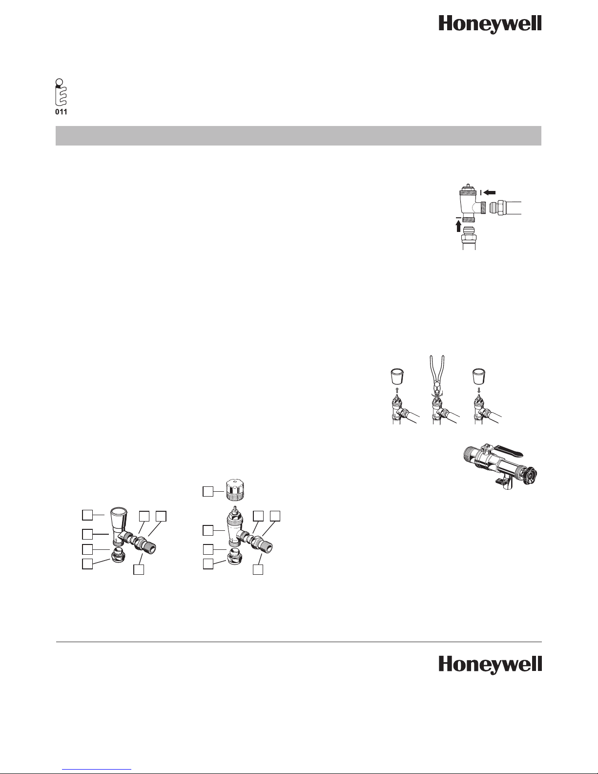
3. Component parts
Maximum working pressure 10 bar (140 psi)
Closing time 20 minutes
To ensure that the valve will thermostatically close the
Maximum differential pressure to ensure reliable and quiet
operation is 0.2 bar.
1. Handwheel
2. Cover cap
3. Lockshield valve
4. Olive
5. Nut
6. Tail piece
7. Valve body V120EUBGB15
2
3
7
4
5
4
5
4 5
4 5
differential pressure must not exceed 1.0 bar.
Whilst Honeywell takes all reasonable and practical steps to
design and manufacture its products to comply with the
requirements of the Health and Safety at Work Act 1974, all
products must be properly used and purchasers are reminded
that their obligations under the Act are to ensure that the
installation and operation such products at place of work
should be safe and without risk to health.
Honeywell reserves the right at anytime and without notice to
change any product or any information contained in this
publication.
This product complies with BS 6284 Part 2 and EN215.
6
6
1
4. To shut off the manual valve
When removing the radiator for any reason the handwheel
supplied with the valve should be used to isolate the flow.
5. Fitting valve and lockshield
Copper Connections
Cut copper tube to an entry
depth of 10mm.
Radiator Connections
Screw 1/2’’ tailpiece into the tapping on radiator.
10mm
10mm
6. Lockshield valve
Install the lockshield opposite from manual valve.
1. Remove cover cap.
2. Turn the spindle clockwise till stop by using a pliers
3. Fit cover cap.
7. To shut off the lockshield valve
8. Servicing
Use the WV108M tool for cleaning
or replacement of the valve insert
without draining the system.
9. Check list
• Consider the use of an automatic by-pass valve
(e.g. Honeywell DU145) to ensure the specification is
adhered to.
• Check all connections for securing and leaks.
• Use clean pipework, free from swarf.
• Do not allow heat from blow torch onto body.
• Do not overtighten the head/body connection.
OPEN
SHUT
Honeywell Control Systems Ltd.
Honeywell House
Arlington Business Park
Bracknell, Berkshire RG12 1EB
T (0 13 44) 65 60 00
F (0 13 44) 65 62 40
www.Honeywelluk.com
EN1H-0417GE25-R1211
50071339-001 Rev. A
December 2011
© 2011 Honeywell International Inc.
Subject to change without notice
Manufactured for and on behalf of the Environmental and Combustion
Controls Division of Honeywell Technologies Sàrl, Rolle, Z.A.
La Pièce 16, Switzerland or its authorized representative.
Honeywell TRVs are recognised by the Energy Savings Trust.
UK Head Office
 Loading...