

Page 1
VH2, VH3, VH4, VH5, VH6, VH7, VH8
ANSI 150 Class High Performance
Butterfly Valves
PRODUCT DATA
Two-Way Valves (VH2)
• Sizes from 2 to 24 inches with ANSI Class 125/150 lug
pipe connections
• Modified equal percentages flow characteristic
• Spring fail safe available on 2 to 4 inch models,
Electronic fail safe available on 5 and 6 inch models
• NEMA 2 actuators available on valves 2 to 4 inch,
NEMA 4X available on valves 5 to 24 inch
Three-Way Valve Assemblies (VH3,4,5,6,7,8)
• Sizes from 2 to 16 inches with ANSI Class 125/150 lug
pipe connections.
• Mixing (VH3,4,5) or diverting (VH6,7,8) control.
• Modified linear flow characteristic.
• Standard cast-iron pipe T included.
FEATURES
All Models
• ANSI Class 150
• 316 stainless steel disks
• Carbon steel valve body
• Stainless steel valve stem
• RTFE valve seat
• 0% leakage at rated close-off
• Maximum velocity of 32 FPS
• Close-off rating of 150 psid in all sizes
• ISO 5211 actuator mounting flange
• Available with factory-installed electric actuation
interfaces in 2-position, Floating (“tri-state”), or
Modulating (2-10 Vdc) Control
• Manual override on all models
• For use with hot, chilled or condensing water up to 60%
glycol and on/off control of steam up to 50 psi in HVAC
systems
• Multiple port configurations available to fit different
applications.
• Electronic fail safe available on 2 to 3 inch models
• NEMA 2 actuators available on valves 3 inch and
smaller, NEMA 4X available on valves 4 inch to 16 inch
Contents
FEATURES ..................................................................................... 1
SPECIFICATIONS ........................................................................ 2
DIMENTIONAL DRAWINGS .................................................... 5
ACTUATOR SPECIFICATIONS ................................................ 13
3-WAY VALVE CONFIGURATIONS ........................................ 16
INSTALLATION ............................................................................ 18
ELECTRICAL INSTALLATION ................................................ 22
31-00191EF-02
Page 2

VH2, VH3, VH4, VH5, VH6, VH7, VH8 ANSI 150 CLASS HIGH PERFORMANCE BUTTERFLY VALVES
SPECIFICATIONS
NOTE: All specifications were accurate at time of publica-
tion. Honeywell reserves the right to improve or
discontinue products without prior notification. To
obtain the latest technical literature, please consult the website at
http://
Models: See Table 1
Dimensions: See Figures 1 - 8
Mounting: ASME/ANSI Class 150
Body Style:
Two-way or Three-way ANSI class 150 High Performance
butterfly valves
Body Size:
2-way valves: 2 in. to 24 in.
3-way valves: 2 in. to 16 in.
Flow Characteristics:
2-way valves: Modified equal percentage, unidirectional
3-way valves: Modified linear, unidirectional
Body Static Pressure Rating (maximum):
285 psi at 100 °F (1965 kPa at 38 °C)
Close-Off Pressure Rating (maximum differential):
150 psi
Controlled Media: Chilled or hot water up to 60% glycol,
steam up to 50 psi
Media temperature range: -22 °F to 400 °F
(-30 °C to 204 °C)
Maximum Velocity: 32 fps (9.8 m/s)
Materials:
Body: Carbon steel full lug
Disk: 316 stainless steel
Shaft: 17-4 PH stainless
Seat: RTFE
Gland Seal: TFE
Bearings: Glass backed PTFE
Approvals/Standards:
Close-off: 0% leakage up to rated close-off.
Actuators on 6 inch and smaller two-way valves and 4 inch
and smaller three-way valves: cULus, CE
Actuators on 8 inch and larger 2-way valves and 5 inch and
larger three-way valves: cCSAus, CE
Actuator Ratings: See Table 6
Accessories:
MB-NSR-SWITCH: NSR DCA Aux Switch
MB-NSR-N4HEAT: NSR NEMA4 DCA Heater Kit
(Must be ordered with valve, factory installed)
MB-SR-N4HEAT: SR NEMA4 DCA Heater Kit
(Must be ordered with valve, factory installed)
31-00191EF—02 2
Page 3

VH2, VH3, VH4, VH5, VH6, VH7, VH8 ANSI 150 CLASS HIGH PERFORMANCE BUTTERFLY VALVES
Table 1. Butterfly Valve Assembly Model Selection.
Type
Valve
Butterfly
Connection
Valve, Lugged (Butterfly)
V
H
Valve
Pattern
High Performance ANSI 150
2-Way
2
Control
Actuator
Actuator
Volta ge
Fail Safe
Nema
Function
Volta ge/Swit ch
Size
Body
3
3-way Mixing Configurations (See Fig. 9)
4
5
6
3-Way Diverting Configurations (See Fig. 9 )
7
8
2 inch (DN 50)
F
2.5 inch (DN 65)
G
3 inch (DN 80)
H
4 inch (DN 100)
J
5 inch (DN 125)
K
6 inch (DN 150)
L
8 inch (DN 200)
M
10 inch (DN 250)
N
12 inch (DN 300)
P
14 inch (DN 350)
R
16 inch (DN 400)
S
18 inch (DN 450) 2-Way Only
T
20 inch (DN 500) 2-Way Only
U
24 inch (DN 600) 2-Way Only
V
Floating / Two-Position (SPDT)
6
Analog Modulating (0)2-10 Vdc
7
Two- Positio n (SPST )
8
24 Vac/Vdc
L
120 Vac
H
24-240 Vac / 24-125 Vdc
U
Fail in Place
P
Spring Return A-Port (Master) Fail-Safe Open
S
Spring Return A-Port (Master) Fail-Safe Closed
T
Electronic Fail-Safe (Default Fail Closed, Field Adjustable)
E
No Feedback
N
Analog Feedback
F
Built in Aux Switches
S
Both Analog Feedback and Aux Switches
B
NEMA 2
2
NEMA 4X
4
NEMA 4X (with Heater)
H
VH2H7LPF2
EXAMPLE: 2-WAY, 3 INCH, ANSI CLASS 150 HIGH PERFORMANCE BUTTERFLY VALVE, CV228, CLOSE-OFF 285PSI,
24VAC, 2-10VDC, 150S, FAIL-SAFE IN PLACE, FEEDBACK, NEMA2, (INCLUDES MBP7L4F2/U ACTUATOR)
Description
3 31-00191EF—02
Page 4

VH2, VH3, VH4, VH5, VH6, VH7, VH8 ANSI 150 CLASS HIGH PERFORMANCE BUTTERFLY VALVES
Table 2. Butterfly Valve Replacement Actuator Model Selection.
Type
Control
Fail safe
Type
Power
Actuator
Feedback
MB Motor Butterfly
S Spring Fail-Safe
E Electronic Fail-Safe
P Fail-in -place
6 Floating / Two-Position (SPDT)
7 Analog Modulating (0)2-10 Vdc
8 Two-Position (SPST)
L 24 Vac/Vdc
U 24-240 Vac / 24-125 Vdc
H 120 Vac
1 SR 180 in-lb
2 NSR 180 in-lb
3 SR 180 in-lb
A NSR 180 in-lb
4 EFS/FIP 360 in-lb (2-Way VR)
R EFS/FIP 360 in-lb (VH and 3-Way VR)
5 EFS/FIP 800 in-lb
6 EFS/FIP 1400 in-lb
7 EFS/FIP 1400 in-lb
8 EFS/FIP 1400 in-lb
9 FIP 3540 in-lb
B FIP 4425 in-lb
C FIP 5755 in-lb
D FIP 8850 in-lb
E FIP 13275 in-lb
F FIP 17700 in-lb
G FIP 22125 in-lb
H FIP 26550 in-lb
N No Feedback
F Analog Feedback
S Built in Aux Switches
B Both Analog Feedback and Aux Switches
MB S 8 U 1 N 2
Nema
Description
2 NEMA 2
4 NEMA 4X
H NEMA 4X (with Heater)
Example: BUTTERFLY VALVE ACTUATOR FOR VR AND VH SERIES, SPRING RETURN, 2-POSITION,
24-240VAC, 180 LB-IN, NEMA2.
NOTE: The tables above are intended to explain the significance of the butterfly valve and actuator part numbering sys-
tem, and is not a product configuration tool. Only part numbers printed in Honeywell price books may be ordered.
Please refer to cpq.honeywell.com for available configurations.
31-00191EF—02 4
Page 5
VH2, VH3, VH4, VH5, VH6, VH7, VH8 ANSI 150 CLASS HIGH PERFORMANCE BUTTERFLY VALVES
E
D
BC
A
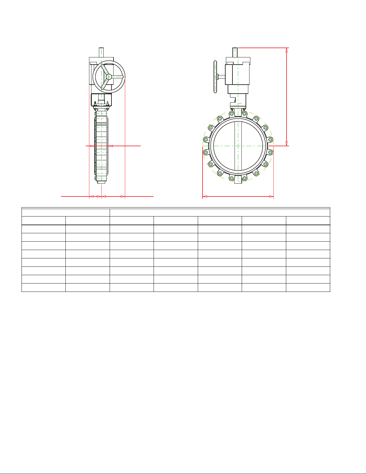
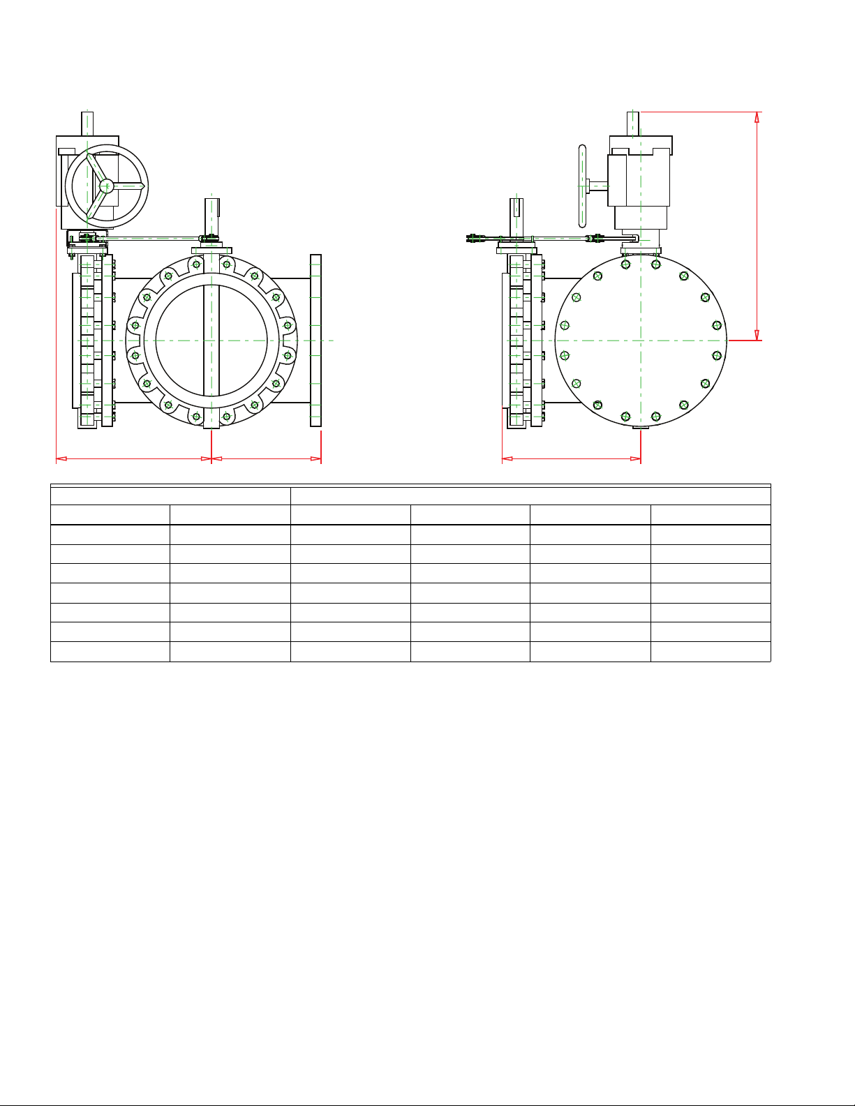
DIMENTIONAL DRAWINGS
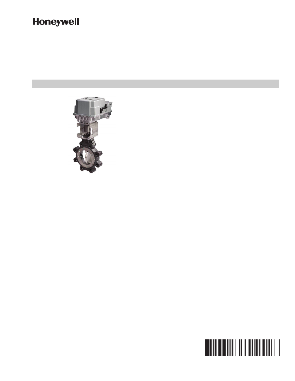
Size Dimensions, in. (mm)
in. DN A B C D E
2 50 1.77 (45.0) 8.49 (215.6) 8.49 (215.6) 14.25 (362.0) 5.77 (146.6)
2.5 65 1.90 (48.3) 8.49 (215.6) 8.49 (215.6) 14.25 (362.0) 6.52 (165.6)
3 80 1.90 (48.3) 8.49 (215.6) 8.49 (215.6) 14.99 (380.7) 7.02 (178.3)
4 100 2.15 (54.6) 8.49 (215.6) 8.49 (215.6) 15.75 (400.1) 8.52 (216.4)
Fig. 1. 2-way valves with MBP...R actuators.
5 31-00191EF—02
Page 6
VH2, VH3, VH4, VH5, VH6, VH7, VH8 ANSI 150 CLASS HIGH PERFORMANCE BUTTERFLY VALVES
A
D
BC
E
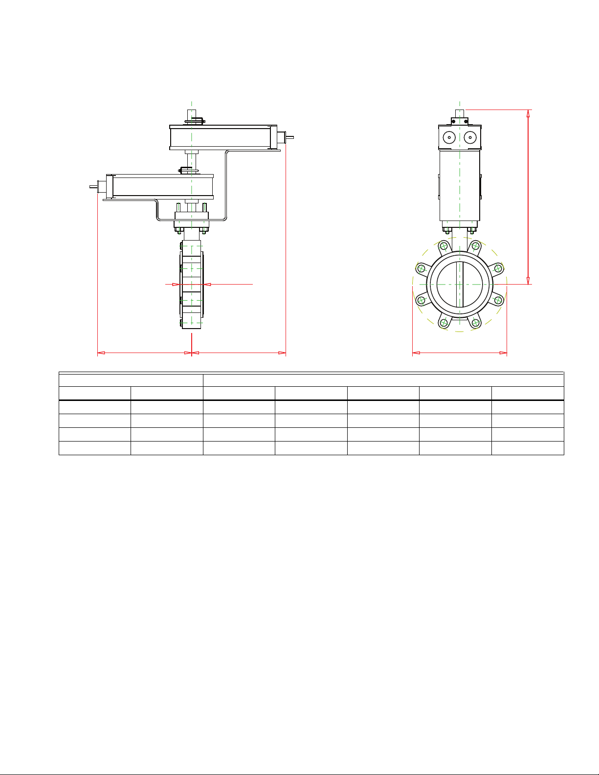
Size Dimensions, in. (mm)
in.DNABCDE
2 50 1.77 (45.0) 1.42 (36.1) 7.64 (194.1) 9.21 (233.9) 5.77 (146.6)
2.5 65 1.90 (48.3) 1.42 (36.1) 7.64 (194.1) 9.21 (233.9) 6.52 (165.6)
3 80 1.90 (48.3) 1.42 (36.1) 7.64 (194.1) 9.95 (252.7) 7.02 (178.3)
4 100 2.15 (54.6) 1.42 (36.1) 7.64 (194.1) 13.36 (339.3) 8.52 (216.4)
Fig. 2. 2-way valves with tandem MBS...1 actuators.
31-00191EF—02 6
Page 7
VH2, VH3, VH4, VH5, VH6, VH7, VH8 ANSI 150 CLASS HIGH PERFORMANCE BUTTERFLY VALVES
E
D
BC
A
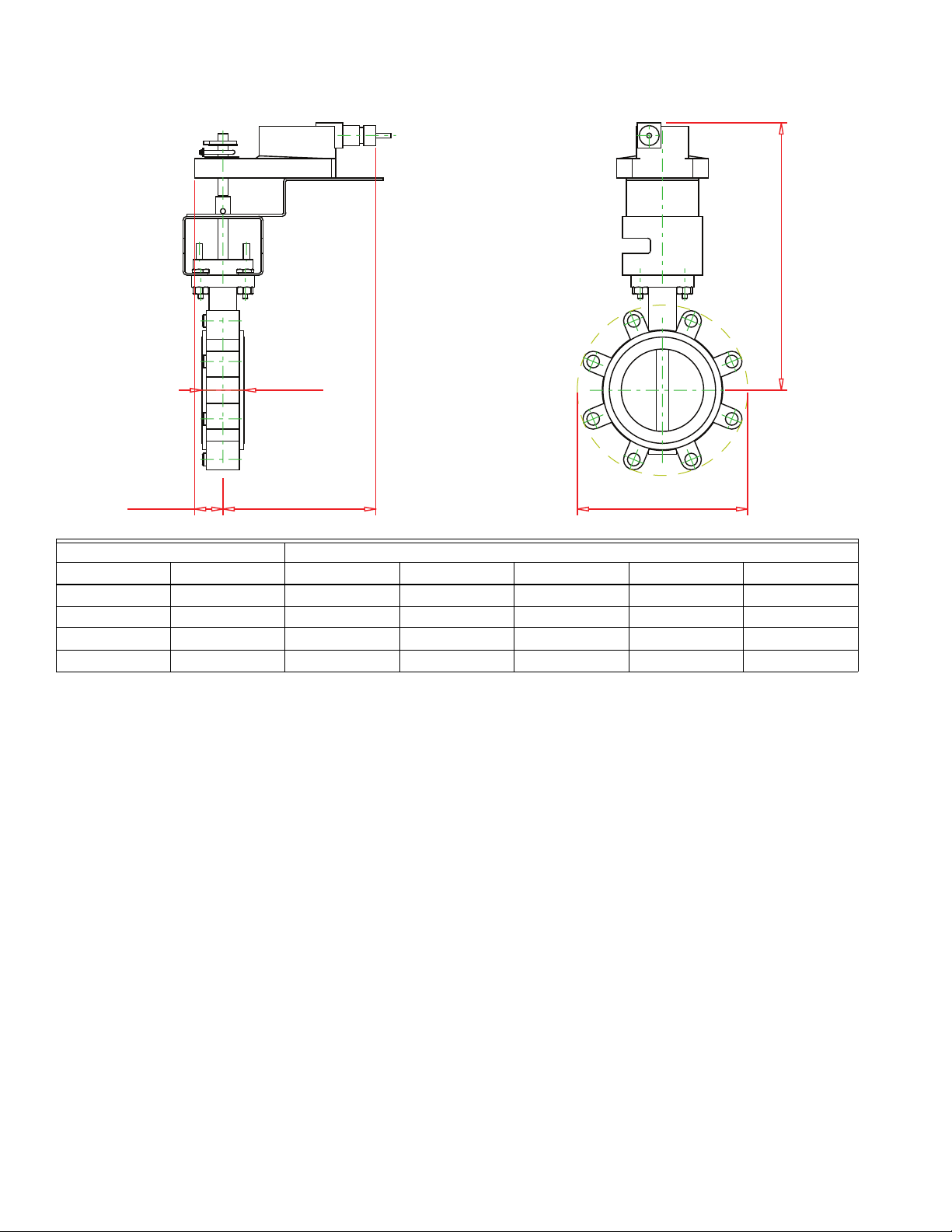
Size Dimensions, in. (mm)
in. DN A B C D E
5 125 2.31 (58.7) 2.40 (61.0) 9.55 (242.6) 18.98 (482.1) 9.76 (247.9)
6 150 2.31 (58.7) 2.40 (61.0) 9.55 (242.6) 19.52 (495.8) 10.76 (273.3)
Fig. 3. 2-way valves with MBE...6 actuators.
7 31-00191EF—02
Page 8
VH2, VH3, VH4, VH5, VH6, VH7, VH8 ANSI 150 CLASS HIGH PERFORMANCE BUTTERFLY VALVES
E
D
BC
A
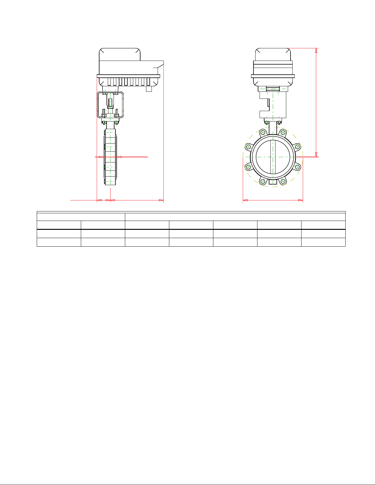
Size Dimensions, in. (mm)
in.DNABCDE
8 200 2.48 (63.0) 4.40 (111.8) 7.13 (181.1) 23.14 (587.8) 13.17 (334.5)
10 250 2.81 (71.4) 4.40 (111.8) 7.13 (181.1) 23.89 (606.8) 15.89 (403.6)
12 300 3.22 (81.8) 4.40 (111.8) 7.13 (181.1) 27.49 (698.2) 18.62 (472.9)
14 350 3.22 (81.8) 4.40 (111.8) 7.13 (181.1) 28.10 (713.7) 20.75 (527.1)
16 400 4.22 (107.2) 4.27 (108.5) 8.35 (212.1) 33.13 (841.5) 22.89 (581.4)
18 450 4.71 (119.6) 4.27 (108.5) 8.35 (212.1) 34.44 (874.8) 24.96 (634.0)
20 500 5.25 (133.4) 8.59 (218.2) 7.20 (182.9) 41.32 (1049.5) 26.89 (683.0)
24 600 6.36 (161.5) 8.59 (218.2) 7.20 (182.9) 43.44 (1103.4) 31.28 (794.5)
Fig. 4. 2-way valves with MBP...9,B,D,F,G actuators.
31-00191EF—02 8
Page 9
VH2, VH3, VH4, VH5, VH6, VH7, VH8 ANSI 150 CLASS HIGH PERFORMANCE BUTTERFLY VALVES
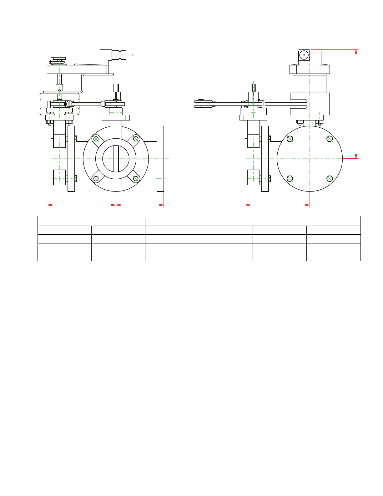
B
D
CA
Size Dimensions, in. (mm)
in.DNABCD
2 50 4.50 (114.3) 6.23 (158.2) 6.78 (172.2) 11.75 (298.5)
2.5 65 5.00 (127.0) 6.89 (175.0) 7.37 (187.2) 14.25 (362.0)
3 80 5.50 (139.7) 7.43 (188.7) 7.88 (200.2) 12.50 (317.5)
Fig. 5. 3-way valves with MBP...R actuators.
9 31-00191EF—02
Page 10
VH2, VH3, VH4, VH5, VH6, VH7, VH8 ANSI 150 CLASS HIGH PERFORMANCE BUTTERFLY VALVES
D
BCA
Size Dimensions, in. (mm)
in.DNABCD
2 50 4.50 (114.3) 6.23 (158.2) 6.79 (172.5) 12.47 (316.7)
2.5 65 5.00 (127.0) 6.89 (175.0) 7.36 (186.9) 9.64 (244.9)
3 80 5.50 (139.7) 7.43 (188.7) 7.89 (200.4) 13.22 (335.8)
Fig. 6. 3-way valves with MBE...R actuators.
31-00191EF—02 10
Page 11
VH2, VH3, VH4, VH5, VH6, VH7, VH8 ANSI 150 CLASS HIGH PERFORMANCE BUTTERFLY VALVES
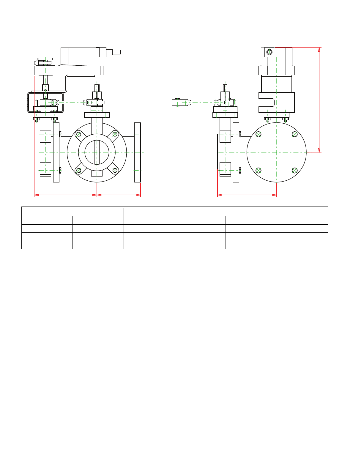
D
BCA
Size Dimensions, in. (mm)
in. DN A B C D
4 100 6.50 (165.1) 8.62 (218.9) 9.96 (253.0) 16.02 (406.9)
Fig. 7. 3-way valves with MBP...6 actuators.
11 31-00191EF—02
Page 12
VH2, VH3, VH4, VH5, VH6, VH7, VH8 ANSI 150 CLASS HIGH PERFORMANCE BUTTERFLY VALVES
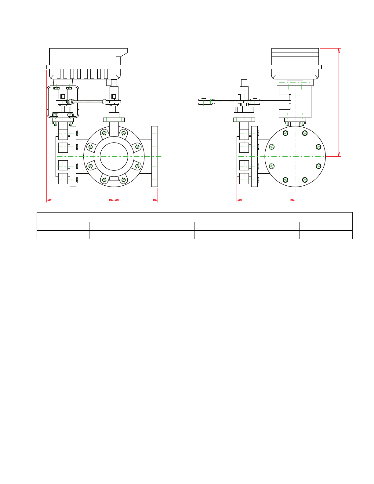
D
BCA
Size Dimensions, in. (mm)
in.DNABCD
5 125 7.50 (191) 10.00 (254) 13.50 (343) 21.00 (533)
6 150 8.00 (203) 10.30 (262) 13.50 (343) 23.40 (594)
8 200 9.00 (228.6) 11.50 (292.1) 14.65 (372.1) 23.14 (587.8)
10 250 11.00 (279.4) 13.81 (350.8) 16.80 (426.7) 23.90 (607.1)
12 300 12.00 (304.8) 15.22 (386.6) 18.01 (457.5) 25.65 (651.5)
14 350 14.00 (355.6) 17.62 (447.5) 20.08 (510.0) 29.84 (757.9)
16 400 15.00 (381.0) 19.00 (482.6) 21.27 (540.3) 31.29 (794.8)
Fig. 8. 3-way valves with MBP...9,B,D,E actuators.
31-00191EF—02 12
Page 13

VH2, VH3, VH4, VH5, VH6, VH7, VH8 ANSI 150 CLASS HIGH PERFORMANCE BUTTERFLY VALVES
ACTUATOR SPECIFICATIONS
Table 3. Actuators Used on 2-Way Assemblies.
Assembly Actuator Assembly Actuator Assembly Actuator
VH2F6LPN2/M MBP6LRN2/U VH2H7LTF2/M MBS7L1F2/U VH2N6LPSH/M MBP6L9SH/U
VH2F7LPF2/M MBP7LRF2/U VH2H8LSN2/M MBS8L1N2/U VH2N7LPBH/M MBP7L9SH/U
VH2F7LSF2/M MBS7L1F2/U VH2H8LTN2/M MBS8L1N2/U VH2P6LPSH/M MBP6L9SH/U
VH2F7LTF2/M MBS7L1F2/U VH2J6LPN2/M MBP6LRN2/U VH2P7LPBH/M MBP7L9SH/U
VH2F8LSN2/M MBS8L1N2/U VH2J7LPF2/M MBP7LRF2/U VH2R6LPSH/M MBP6LBSH/U
VH2F8LTN2/M MBS8L1N2/U VH2J7LSF2/M MBS7L1F2/U VH2R7LPBH/M MBP7LBBH/U
VH2G6LPN2/M MBP6LRN2/U VH2J7LTF2/M MBS7L1F2/U VH2S6HPSH/M MBP6HDSH/U
VH2G7LPF2/M MBP7LRF2/U VH2J8LSN2/M MBS8L1N2/U VH2S7HPBH/M MBP7HDBH/U
VH2G7LSF2/M MBS7L1F2/U VH2J8LTN2/M MBS8L1N2/U VH2T6HPSH/M MBP6HDSH/U
VH2G7LTF2/M MBS7L1F2/U VH2K6UESH/M MBE6U6SH/U VH2T7HPBH/M MBP7HDBH/U
VH2G8LSN2/M MBS8L1N2/U VH2K7UEBH/M MBE7U6BH/U VH2U6HPSH/M MBP6HFSH/U
VH2G8LTN2/M MBS8L1N2/U VH2L6UESH/M MBE6U6SH/U VH2U7HPBH/M MBP7HFBH/U
VH2H6LPN2/M MBP6LRN2/U VH2L7UEBH/M MBE7U6BH/U VH2V6HPSH/M MBP6HGSH/U
VH2H7LPF2/M MBP7LRF2/U VH2M6LPSH/M MBP6L9SH/U VH2V7HPBH/M MBP7HGBH/U
VH2H7LSF2/M MBS7L1F2/U VH2M7LPBH/M MBP7L9SH/U
Assembly Actuator Assembly Actuator Assembly Actuator
VH3F6LPN2/M MBP6LRN2/U VH4F6LPN2/M MBP6LRN2/U VH5F6LPN2/M MBP6LRN2/U
VH3F7LEF2/M MBE7LRF2/U VH4F7LEF2/M MBE7LRF2/U VH5F7LEF2/M MBE7LRF2/U
VH3F7LPF2/M MBP7LRF2/U VH4F7LPF2/M MBP7LRF2/U VH5F7LPF2/M MBP7LRF2/U
VH3F8LEN2/M MBE6LRN2/U VH4F8LEN2/M MBE6LRN2/U VH5F8LEN2/M MBE6LRN2/U
VH3G6LPN2/M MBP6LRN2/U VH4G6LPN2/M MBP6LRN2/U VH5G6LPN2/M MBP6LRN2/U
VH3G7LEF2/M MBE7LRF2/U VH4G7LEF2/M MBE7LRF2/U VH5G7LEF2/M MBE7LRF2/U
VH3G7LPF2/M MBP7LRF2/U VH4G7LPF2/M MBP7LRF2/U VH5G7LPF2/M MBP7LRF2/U
VH3G8LEN2/M MBE6LRN2/U VH4G8LEN2/M MBE6LRN2/U VH5G8LEN2/M MBE6LRN2/U
VH3H6LPN2/M MBP6LRN2/U VH4H6LPN2/M MBP6LRN2/U VH5H6LPN2/M MBP6LRN2/U
VH3H7LEF2/M MBE7LRF2/U VH4H7LEF2/M MBE7LRF2/U VH5H7LEF2/M MBE7LRF2/U
VH3H7LPF2/M MBP7LRF2/U VH4H7LPF2/M MBP7LRF2/U VH5H7LPF2/M MBP7LRF2/U
VH3H8LEN2/M MBE6LRN2/U VH4H8LEN2/M MBE6LRN2/U VH5H8LEN2/M MBE6LRN2/U
VH3J6UPSH/M MBP6U6SH/U VH4J6UPSH/M MBP6U6SH/U VH5J6UPSH/M MBP6U6SH/U
VH3J7UPBH/M MBP7U6BH/U VH4J7UPBH/M MBP7U6BH/U VH5J7UPBH/M MBP7U6BH/U
VH3K6UPSH/M MBP6L9SH/U VH4K6UPSH/M MBP6L9SH/U VH5K6UPSH/M MBP6L9SH/U
VH3K7UPBH/M MBP7L9SH/U VH4K7UPBH/M MBP7L9SH/U VH5K7UPBH/M MBP7L9SH/U
VH3L6LPSH/M MBP6L9SH/U VH4L6LPSH/M MBP6L9SH/U VH5L6LPSH/M MBP6L9SH/U
VH3L7LPBH/M MBP7L9SH/U VH4L7LPBH/M MBP7L9SH/U VH5L7LPBH/M MBP7L9SH/U
VH3M6LPSH/M MBP6L9SH/U VH4M6LPSH/M MBP6L9SH/U VH5M6LPSH/M MBP6L9SH/U
VH3M7LPBH/M MBP7L9SH/U VH4M7LPBH/M MBP7L9SH/U VH5M7LPBH/M MBP7L9SH/U
VH3N6LPSH/M MBP6L9SH/U VH4N6LPSH/M MBP6L9SH/U VH5N6LPSH/M MBP6L9SH/U
VH3N7LPBH/M MBP7L9SH/U VH4N7LPBH/M MBP7L9SH/U VH5N7LPBH/M MBP7L9SH/U
VH3P6LPSH/M MBP6LBSH/U VH4P6LPSH/M MBP6LBSH/U VH5P6LPSH/M MBP6LBSH/U
VH3P7LPBH/M MBP7LBBH/U VH4P7LPBH/M MBP7LBBH/U VH5P7LPBH/M MBP7LBBH/U
VH3R6HPSH/M MBP6HDSH/U VH4R6HPSH/M MBP6HDSH/U VH5R6HPSH/M MBP6HDSH/U
VH3R7HPBH/M MBP7HDBH/U VH4R7HPBH/M MBP7HDBH/U VH5R7HPBH/M MBP7HDBH/U
VH3S6HPSH/M MBP6HDSH/U VH4S6HPSH/M MBP6HDSH/U VH5S6HPSH/M MBP6HDSH/U
VH3S7HPBH/M MBP7HDBH/U VH4S7HPBH/M MBP7HDBH/U VH5S7HPBH/M MBP7HDBH/U
Table 4. Actuators Used on 3-way Mixing Assemblies.
13 31-00191EF—02
Page 14

VH2, VH3, VH4, VH5, VH6, VH7, VH8 ANSI 150 CLASS HIGH PERFORMANCE BUTTERFLY VALVES
Table 5. Actuators Used on 3-Way Diverting Assemblies.
Assembly Actuator Assembly Actuator Assembly Actuator
VH6F6LPN2/M MBP6LRN2/U VH7F6LPN2/M MBP6LRN2/U VH8F6LPN2/M MBP6LRN2/U
VH6F7LEF2/M MBE7LRF2/U VH7F7LEF2/M MBE7LRF2/U VH8F7LEF2/M MBE7LRF2/U
VH6F7LPF2/M MBP7LRF2/U VH7F7LPF2/M MBP7LRF2/U VH8F7LPF2/M MBP7LRF2/U
VH6F8LEN2/M MBE6LRN2/U VH7F8LEN2/M MBE6LRN2/U VH8F8LEN2/M MBE6LRN2/U
VH6G6LPN2/M MBP6LRN2/U VH7G6LPN2/M MBP6LRN2/U VH8G6LPN2/M MBP6LRN2/U
VH6G7LEF2/M MBE7LRF2/U VH7G7LEF2/M MBE7LRF2/U VH8G7LEF2/M MBE7LRF2/U
VH6G7LPF2/M MBP7LRF2/U VH7G7LPF2/M MBP7LRF2/U VH8G7LPF2/M MBP7LRF2/U
VH6G8LEN2/M MBE6LRN2/U VH7G8LEN2/M MBE6LRN2/U VH8G8LEN2/M MBE6LRN2/U
VH6H6LPN2/M MBP6LRN2/U VH7H6LPN2/M MBP6LRN2/U VH8H6LPN2/M MBP6LRN2/U
VH6H7LEF2/M MBE7LRF2/U VH7H7LEF2/M MBE7LRF2/U VH8H7LEF2/M MBE7LRF2/U
VH6H7LPF2/M MBP7LRF2/U VH7H7LPF2/M MBP7LRF2/U VH8H7LPF2/M MBP7LRF2/U
VH6H8LEN2/M MBE6LRN2/U VH7H8LEN2/M MBE6LRN2/U VH8H8LEN2/M MBE6LRN2/U
VH6J6UPSH/M MBP6U6SH/U VH7J6UPSH/M MBP6U6SH/U VH8J6UPSH/M MBP6U6SH/U
VH6J7UPBH/M MBP7U6BH/U VH7J7UPBH/M MBP7U6BH/U VH8J7UPBH/M MBP7U6BH/U
VH6K6UPSH/M MBP6L9SH/U VH7K6UPSH/M MBP6L9SH/U VH8K6UPSH/M MBP6L9SH/U
VH6K7UPBH/M MBP7L9SH/U VH7K7UPBH/M MBP7L9SH/U VH8K7UPBH/M MBP7L9SH/U
VH6L6LPSH/M MBP6L9SH/U VH7L6LPSH/M MBP6L9SH/U VH8L6LPSH/M MBP6L9SH/U
VH6L7LPBH/M MBP7L9SH/U VH7L7LPBH/M MBP7L9SH/U VH8L7LPBH/M MBP7L9SH/U
VH6M6LPSH/M MBP6L9SH/U VH7M6LPSH/M MBP6L9SH/U VH8M6LPSH/M MBP6L9SH/U
VH6M7LPBH/M MBP7L9SH/U VH7M7LPBH/M MBP7L9SH/U VH8M7LPBH/M MBP7L9SH/U
VH6N6LPSH/M MBP6L9SH/U VH7N6LPSH/M MBP6L9SH/U VH8N6LPSH/M MBP6L9SH/U
VH6N7LPBH/M MBP7L9SH/U VH7N7LPBH/M MBP7L9SH/U VH8N7LPBH/M MBP7L9SH/U
VH6P6LPSH/M MBP6LBSH/U VH7P6LPSH/M MBP6LBSH/U VH8P6LPSH/M MBP6LBSH/U
VH6P7LPBH/M MBP7LBBH/U VH7P7LPBH/M MBP7LBBH/U VH8P7LPBH/M MBP7LBBH/U
VH6R6HPSH/M MBP6HDSH/U VH7R6HPSH/M MBP6HDSH/U VH8R6HPSH/M MBP6HDSH/U
VH6R7HPBH/M MBP7HDBH/U VH7R7HPBH/M MBP7HDBH/U VH8R7HPBH/M MBP7HDBH/U
VH6S6HPSH/M MBP6HDSH/U VH7S6HPSH/M MBP6HDSH/U VH8S6HPSH/M MBP6HDSH/U
VH6S7HPBH/M MBP7HDBH/U VH7S7HPBH/M MBP7HDBH/U VH8S7HPBH/M MBP7HDBH/U
31-00191EF—02 14
Page 15
VH2, VH3, VH4, VH5, VH6, VH7, VH8 ANSI 150 CLASS HIGH PERFORMANCE BUTTERFLY VALVES
Table 6. Actuator Specification Data.
Actuator
Model Torque
MBS8L1N2/U
MBS7L1F2/U Modulating Fig. 17
MBP6LRN2/U
MBP7LRF2/U Modulating 7 VA (class 2) Fig. 17
MBE6LRN2/U
MBE7LRF2/U Modulating Fig. 19
MBP6U6SH/U
MBP7U6BH/U Modulating Fig. 21
MBE6U6SH/U
MBE7U6BH/U Modulating Fig. 21
MBP6L9SH/U
MBP7L9SH/U Modulating Fig. 24
MBP6LBSH/U
MBP7LBBH/U Modulating Fig. 24
MBP6HDSH/U
MBP7HDBH/U Modulating 240 VA 59s Fig. 26
MBP6HESH/U
MBP7HEBH/U Modulating 336 VA 79s Fig. 26
MBP6HFSH/U
MBP7HFBH/U Modulating 324 VA 65s Fig. 26
MBP6HGSH/U
MBP7HGBH/U Modulating 360 VA 76s Fig. 26
180 in-lb
(20 Nm)
360 in-lb
(40 Nm)
360 in-lb
(40 Nm)
1400 in-lb
(160 Nm)
1400 in-lb
(160 Nm)
3540 in-lb
(400 Nm)
4425 in-lb
(500 Nm)
8850 in-lb
(1000 Nm)
13275 in-lb
(1500 Nm)
17700 in-lb
(2000 Nm)
22125 in-lb
(2500 Nm)
Control
Inputs
2-position
2-position;
Floating Fail-in-
2-position;
Floating
2-position;
Floating
2-position;
Floating Electronic
2-position
2-position
2-position
2-position 504 VA 51s Fig. 25
2-position 360 VA 62s Fig. 25
2-position 384 VA 62s Fig. 25
Fail Safe
(Timing) Supply Voltage
Spring
fail-safe
(<20s)
place
Electronic
fail-safe
(35s)
Fail-in-
place
fail-safe
(30s)
Fail-in-
place
Fail-in-
place
24 VAC, ±20%, 50/60 Hz;
24 VDC, -10% / +20%
24 VAC, ±20%, 50/60 Hz;
24 VDC, ±10%
24 VAC ± 20%, 50/60 Hz;
24 VDC ± 10%
24...240 VAC, -20% /
+10%, 50/60 Hz;
24...125 VDC, -20% / +10%
24...240 VAC, -20% /
+10%, 50/60 Hz;
24...125 VDC, -20% / +10%
24 VAC, ±10%, 50/60 Hz;
24 VDC, ±10%
120 VAC, ±10%, 50/60 Hz
Tran sfor mer
Sizing
10 VA (class 2)
6 VA (class 2)
21 VA (class 2)
20 VA @ 24 VAC/DC
(class 2);
23 VA @
120 VAC/DC;
52 VA @ 230 VAC
55 VA @ 24 VAC/DC
(class 2);
43 VA @
120 VAC/DC;
68 VA @ 230 VAC
226 VA
214 VA 26s
504 VA
Ambient
Temp. Timing Enclosure
-22°F to
122°F
(-30°C to
50°C)
-22°F to
122°F
(-30°C to
50°C)
22°F to
122°F
(-30°C to
50°C)
22°F to
122°F
(-30°C to
50°C)
-22°F to
122°F
(-30°C to
50°C)
-22°F to
150°F
(-30°C to
65°C)
-22°F to
150°F
(-30°C to
65°C)
150s IP 54 NEMA 2
150s IP 54 NEMA 2
150s IP 54 NEMA 2
IP 66/67
35s
NEMA 4X
w/Heater
IP 66/67
35s
NEMA 4X
Heater
w/
20s
IP 66/67
NEMA 4X
w/Heater
50s
IP 66/67
NEMA 4X
w/Heater
Aux.
Switch
2 x SPDT*
2 x SPDT*
2 x SPDT**
2 x SPDT**
Wiring
Diagram
Fig. 15
Fig. 15
Fig. 18
Fig. 20
Fig. 20
Fig. 23
Fig. 23
Fig. 25
*3A resistive (0.5A inductive) @ 250 VAC, one set at 10°, one adjustable 10° to 90°
**3A resistive (0.5A inductive) @ 250 VAC, one set at 10°, one set at 85°
Table 7. Duty Cycle on High Torque Actuators.
Actuator Model Torque Control Inputs Duty Cycle
MBP6L9SH/U
MBP7L9SH/U Modulating
MBP6LBSH/U
MBP7LBBH/U Modulating
MBP6HDSH/U
MBP7HDBH/U Modulating 75%
MBP6HESH/U
MBP7HEBH/U Modulating 75%
MBP6HFSH/U
MBP7HFBH/U Modulating 50%
MBP6HGSH/U
MBP7HGBH/U Modulating 50%
3540 in-lb (400 Nm)
4425 in-lb (500 Nm)
8850 in-lb (1000 Nm)
13275 in-lb (1500 Nm)
17700 in-lb (2000 Nm)
22125 in-lb (2500 Nm)
15 31-00191EF—02
2-position
2-position
75%
2-position 30%
2-position 30%
2-position 30%
2-position 30%
Page 16
VH2, VH3, VH4, VH5, VH6, VH7, VH8 ANSI 150 CLASS HIGH PERFORMANCE BUTTERFLY VALVES
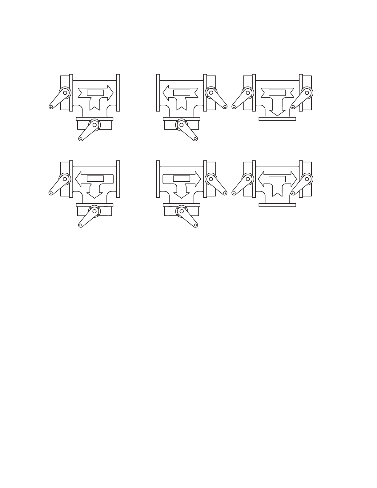
3-WAY VALVE CONFIGURATIONS
VH3 VH4 VH5
MASTERMASTER
MIXINGDIVERTING
MASTER
FLOW
DRONE DRONE
FLOW
DRONE
FLOW
COMMON
VH6 VH7 VH8
DRONE
MASTER
FLOW
COMMON
DRONE
FLOWFLOW
COMMON COMMON
COMMON COMMON
DRONE
Fig. 9. 3-way valve configurations.
MASTER
MASTER
31-00191EF—02 16
Page 17

VH2, VH3, VH4, VH5, VH6, VH7, VH8 ANSI 150 CLASS HIGH PERFORMANCE BUTTERFLY VALVES
Table 8. Valve Cv.
Valve Size Cv
in. DN 10° 20° 30° 40° 50° 60° 70° 80° 90°
2 501.56.1142639567799102
2.5 65 2.2 8.8 20 37 55 80 110 142 146
3 80 3.4 14 32 57 87 125 171 221 228
4 100 6.8 27 63 114 171 248 338 437 451
5 125 11 43 100 180 271 393 536 693 714
6 150 17 66 154 278 419 607 827 1070 1103
8 200 31 124 289 520 784 1135 1548 2002 2064
10 250 53 211 492 886 1336 1934 2638 3411 3517
12 300 73 290 677 1219 1838 2660 3628 4692 4837
14 350 90 392 914 1646 2481 3592 4898 6530 6857
16 400 132 531 1230 2229 3361 4865 6634 8845 9287
18 450 171 684 1596 2873 4332 6270 8550 11270 11400
20 500 307 828 1932 3478 5244 7590 10350 13800 14420
24 600 315 1260 2940 5292 7890 11550 15750 21000 22050
Table 9. Flow Rate.
Valve Size Flow Rate in GPM
in. DN 4 FPS 8 FPS 12 FPS 16 FPS 20 FPS 24 FPS 28 FPS 32 FPS
2 50 39 78 118 157 196 235 274 313
2.5 65 61 122 184 245 306 367 428 490
3 80 88 176 264 353 441 529 617 705
4 100 157 313 470 627 783 940 1097 1253
5 125 245 490 734 979 1224 1469 1714 1958
6 150 352 705 1058 1410 1763 2115 2468 2820
8 200 627 1253 1880 2507 3133 3760 4387 5013
10 250 979 1958 2938 3917 4896 5875 6854 7834
12 300 1410 2820 4230 5640 7050 8460 9870 11280
14 350 1919 3838 5738 7677 9596 11515 13435 15354
16 400 2507 5013 7520 10027 12534 15040 17547 20054
18 450 3173 6345 9518 12690 15863 19036 22208 25381
20 500 3917 7834 11750 15667 19584 23501 27418 31334
24 600 5640 11280 16921 22561 28201 33841 39481 45121
17 31-00191EF—02
Page 18
VH2, VH3, VH4, VH5, VH6, VH7, VH8 ANSI 150 CLASS HIGH PERFORMANCE BUTTERFLY VALVES
VH series valve tag
indicates proper flow
direction.
INSTALLATION
Valve Design
• The VH Series High Performance Butterfly Valve
features a double offset (or, double eccentric) shaft
design to minimize seat abrasion and lower torque. This
double offset design allows the disc to lift off and “cam”
away from the seat as it rotates open.
• The VH series valve always rotates clockwise to close
(when viewed from above) and counterclockwise to
open.
• The valve body has an Overtravel Stop which prevents
the disc from over rotating into the wrong quadrant. This
stop is not to be used as a disc position stop; if the disc
contacts the Overtravel Stop, this means it has rotated
beyond the seat.
• The VH series valve must be installed with the seat in the
upstream position (SUS). Note the arrow on the metal
tag attached to the valve body.
Safety Precautions
• Be sure the line is depressurized and drained.
• Be sure of the pipeline media. Proper care should be
taken for protection against toxic and/or flammable
fluids.
• Never install the valve without an Operator (Manual or
Automatic) already attached to the valve shaft.
• Never remove the Operator from the valve while the
valve is in the pipeline under pressure.
• Always be sure that the disc is in the full-closed position
before installing the valve.
• Take care in handling the valve.
Flange Compatibility
The VH series valve is designed to fit between ANSI Class
150 flanges for valves 2” to 24” in size.
Gasket Compatibility
The VH series valve is designed to accommodate the use of
standard fiber gaskets (such as non-asbestos, flexible
graphite, asbestos or equivalent gasket materials) of 1/16”
or less, meeting the dimensional requirements of ANSI
B16.21-1978. Thick elastomeric gaskets are not
recommended. Metallic wound (Flexitallic) gaskets may
also be used.
Pipe Schedule Compatibility
The VH series valve is designed to allow the disc edge to
rotate into the open position without interference with the
pipeline I.D. in the following pipe schedules:
Table 10. Pipe Compatibility.
Size Pipe Schedule
2" - 12" SCH 80
14" - 24" SCH 40
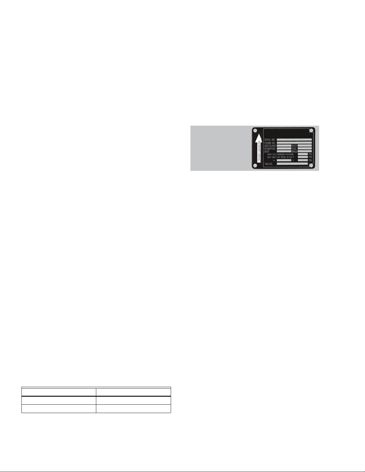
Product Identification
• Every VH series valve has a metal identification tag
attached to the valve body. Information includes the
Figure Number, the Size and Pressure Class, the
Materials of Construction, and the Operating Pressures
and Temperatures.
• Every VH series valve is hydrostatically tested before it is
shipped. The metal tag also includes a Serial Number;
this number, unique for each valve, is recorded by the
Honeywell Quality Control Department along with the
test results and material certification data, for individual
traceability and verification of every valve produced.
Fig. 10. Valve Identification.
Unpacking and Storage Instruction
1. Check the packing list against the valve received to
verify that the quantities, sizes and materials are correct.
2. Check to make sure that the valve and operator were
not damaged during shipment.
3. If the valve is to be stored before being installed, it
should be protected from harsh environmental conditions.
4. Store the valve with the disc in the closed position to
protect the sealing edge and the seat.
5. Keep the valve in a clean location, away from dirt,
debris and corrosive materials.
6. Keep the valve in a dry area with the flange protectors
attached.
7. Keep the valve in a cool location if possible, out of
direct sunlight.
8. If not in use, exercise the butterfly valve (full open
and close) at least once a month.
Storage of Butterfly Valve Assemblies
• Assemblies must be stored indoors, protected from the
elements.
• Materials received on job sites that have long
installation lead times should receive extra protection
from construction damage.
• Valve faces must be protected from abrasion, cutting
and nicking, as this will damage the face and may cause
flange area leaks.
• Electric actuators cannot be stored in wet, damp or
caustic areas.
• Do not store construction material on top of valve
assemblies.
31-00191EF—02 18
Page 19

VH2, VH3, VH4, VH5, VH6, VH7, VH8 ANSI 150 CLASS HIGH PERFORMANCE BUTTERFLY VALVES
WARNING
WARNING
CAUTION
Installation Practices
• VH series butterfly valves are designed to be installed
between ANSI 125/150 flat-faced or raised face, slip-on
weld neck flanges.
• Valve should be installed a minimum of 6 pipe
diameters from upstream or downstream elbows,
strainers, pumps, etc.
• For chilled water, condenser water or hot water
applications, the valve should be installed with the stem
in a vertical orientation, with the actuator mounted
above the valve.
• For applications in which there is a possibility of
sediment in the flow, the valve should be installed with
the stem in a horizontal position and the bottom of the
disc should close FROM the downstream side, rather
than from the upstream side.
• Flange gaskets must be used on VH series BF valves.
• Make sure the flange faces are clean and free of rust,
scale and debris to prevent damage to the flange gasket.
• Follow the recommended flange bolting sequence
found in Fig. 12.
Installation using Welded Flanges
• Mount flanges on both sides of valve body and install
bolts to properly align valve body and both flanges.
• Make sure the valve I.D. and flange internal diameters
are in alignment.
• Take valve body / flange pair assembly and align with
piping ends.
• TACK weld the flanges to the piping in several places. Do
NOT seam weld at this time!
• Remove the lug bolts and carefully remove the valve
body from the flanges.
• Seam weld the entire flange / piping connection for
both flanges.
• Let the piping components cool completely before reinserting the valve body.
Seam welding with the valve body installed
between the flanges can damage the valve seats
due to heat migration through the flange to the
valve body.
Pre-Installation Procedure
1. Remove the protective face covers from the valve.
2. Inspect the valve to be certain the waterway is free
from dirt and foreign matter. Be certain the adjoining
pipeline is free from any foreign material such as rust
and pipe scale or welding slag that could damage the
seat and disc sealing surfaces.
3. Actuators should be mounted on the valve prior to
installation to facilitate proper alignment of the disc
in the valve seat.
4. The valve should be in the closed position. Make sure
the open and closed positions of the actuator correspond to the counter-clockwise to open direction of
rotation of the valve.
5. Cycle the valve to the fully open position, then back to
the fully closed position, checking the actuator travel
stop settings for proper disc alignment.
6. Check the valve identification tag for valve class,
materials, and operating pressure to be sure they are
correct for the application.
Personal injury or property damage may result if
the valve is installed where service conditions
could exceed the valve ratings.
7. Check the flange bolts or studs for proper size,
threading, and length.
REMEMBER: Install the valve with the disc in the fullclosed position using the appropriate flange gaskets on
BOTH valve flange faces.
Valve Installation Procedure
1. The VH Series High Performance Butterfly Valve can
be installed in the pipeline with the shaft in the vertical, horizontal, or other intermediate position above
the pipe centerline (Fig. 11.) Based on applications
experience, however, in media with concentrations of
solid or abrasive particles or media subject to solidification buildup, valve performance and service life will
be enhanced by mounting the valve with the shaft in
the horizontal position.
NOTE: Actuator must be mounted at or above pipe cen-
terline for all actuator types.
2. All VH series valves are directional and must be
mounted in the pipeline with the seat retainer ring
located upstream (sus) to provide maximum seat
protection.
For VH Series valves:
a. Noting the flow direction arrow on the tag, place
the valve between the flanges, making sure the
arrow on the tag points in the direction of the flow.
b. Install the lower flange bolts loosely, leaving
space for the flange gaskets.
c. After inserting the flange gaskets, install the
remaining bolts.
3. Using the sequence shown in Fig. 12, tighten the
flange bolts evenly to assure uniform gasket compression.
The VH series valve should be centered between
the flanges and gaskets to prevent damage to the
disc edge and shaft as a result of the disc striking
the flange, gasket, or pipe.
4. Electricity should be connected to the unit as speci-
fied by the actuator manufacturer.
5. The valve is now ready for operation.
19 31-00191EF—02
Page 20

VH2, VH3, VH4, VH5, VH6, VH7, VH8 ANSI 150 CLASS HIGH PERFORMANCE BUTTERFLY VALVES
90° 90°
31
24
1
4
3
2
5
6
7
8
9
10
11
12
13
14
15
16
1
4
3
2
5
6
7
8
9
10
11
12
1
4
3
2
5
6
7
8
Fig. 11.
Valve Size
(inches)
2 5/8-11 4 2.5 4 2.5 4 1.63 4 1.63
2.5 5/8-11 4 2.75 4 2.75 4 1.85 4 1.85
3 5/8-11 4 3.25 4 2.5 4 2.25 4 1.63
45/8-118 3 82.7582.1281.88
53/4-1083838282
6 3/4-10 8 3.5 8 3 8 2.5 8 1.88
8 3/4-10 8 3.75 8 3.25 8 2.7 8 2.13
10 7/8-9 12 4.25 12 3.5 12 3 12 2.25
12 7/8-9 12 4.75 12 3.5 12 3.45 12 2.35
14 1-8 12 5 12 4 12 3.75 12 2.7
16 1-8 16 5.5 16 4.25 16 4.12 16 2.75
181-1/8-8165.75164.75164.38163.25
20
241-1/4-8207.25205.75205.63204.25
Thread
Size
1-1/8-8166.75164.75165.12163.25
1-1/8-8 4 5.5 4 4.75 4 4.12 4 3.25
QTY
Fig. 12. Bolting Sequence.
Table 11. Flange Bolting Recommendations.
Studs and Nuts Machine Bolts
C
Length
(inches)
D
QTY
Length
(inches)
F
QTY
Length
(inches)
G
QTY
Length
(inches)
31-00191EF—02 20
Page 21

VH2, VH3, VH4, VH5, VH6, VH7, VH8 ANSI 150 CLASS HIGH PERFORMANCE BUTTERFLY VALVES
LUG BOD
HEX HEAD MACHINE BOLT
S
UG BODY
S
TUDS and NUT
S
Y
L
Fig. 13. Bolting.
Fig. 14. Flanges.
Bolting and torque recommendations are made without warranty, and apply only to steel weld-neck or slip-on flanges.
The use of lock washers and/or lubrication with the bolting will affect stated torque values.
Length of machine bolts based on:
1. Gasket thickness of 0.06 inches.
2. Minimum flange thickness of weld-neck flanges per ANSI B16.5 and B16.47 Series A.
* Variation to specified bolting length may result in improper installation.
Table 12. Flange Dimensions.
FLANGES DRILLING BOLTING
Nominal Pipe
Size (inches)
A
Flange
Diameter
(inches)
B
Flange
Thickness
(inches)
C
Diameter of
Bolt Circle
(inches)
D
Diameter of
Bolt Holes
(inches)
Number of
Bolts
Diameter of
Bolts
2 6 0.75 4.75 0.75 4 5/8
2.5 7 0.875 5.5 0.75 4 5/8
3 7.5 0.9375 6 0.75 4 5/8
4 9 0.9375 7.5 0.75 8 5/8
5 10 0.9375 8.5 0.875 8 3/4
6 11 1 9.5 0.875 8 3/4
8 13.5 1.125 11.75 0.875 8 3/4
10 16 1.1875 14.25 1 12 7/8
12 19 1.25 17 1 12 7/8
14 21 1.375 18.75 1.125 12 1
16 23.5 1.4375 21.25 1.125 16 1
18 25 1.625 22.75 1.25 16 1-1/8
20 27.5 1.6875 25 1.25 20 1-1/8
24 32 1.875 29.5 1.375 20 1-1/4
21 31-00191EF—02
Page 22

VH2, VH3, VH4, VH5, VH6, VH7, VH8 ANSI 150 CLASS HIGH PERFORMANCE BUTTERFLY VALVES
2 3
24 VAC Transformer
Blk (1) Common
Red (2) + Hot
Wht (3) + Input
a
Line
Volts
18
Function
100%
Max
a
24 VAC Transformer
Blk (1) Common
Red (2) + Hot
Wht (3) + Input
olts
2 3
18
a
b
Function
100%
Max
a
b
Notes:
On/Off Floating Point
Meets c ULus require ments withou t the need of an
electrical ground connection
2
Actua tors may be conne cted in parall el. Power
consum ption and input i mpedance must b e observed.
3
Actua tors may also be po wered by 24 VDC.
18
Actua tors with plen um rated cable do n ot have numbers
on wires ; use color cod es instead.
V
0
ELECTRICAL INSTALLATION
MBS8U3N2/U and MBS8U3S2/U
Notes:
24 VAC Transformer
Line
Volts
On/Off
2 3
Blk (1) Common
a
Red (2) + Hot
Function
Max
100%
A
18
Meets c ULus require ments withou t the need of an
electrical ground connection
A
Actuators with appliance cables are numbered.
Actua tors may be connected in pa rallel. Power
a
2
consum ption and input i mpedance must be obser ved.
Actua tors may also be p owered by 24 V DC.
3
Actua tors with plen um rated cable do not have numb ers
18
on wires ; use color cod es instead.
Fig. 15. Wiring for MBS8 actuators.
Line
V
Auxiliary Switches
500 Ω
1/4 watt
3 18
Blk
Red
Wht
Pnk
Org
(1)
(2)
(3) Y
(4) Y
(5) U
Common
+ Hot
Input, 2 to 10
1
Input
2
Output, 2 to 1
2-10 VDC or 4 to 20 mA
24 VAC Transformer
Line
Volts
Control Signal
4 to 20 mA or 2 to 10 VDC
Ω
(–)
(+)
7
VDC / 4 to 20 mA Override Control Min, Mid, Max Postions
Fig. 17. Wiring for MBS7...1 and MBS7...R actuators.
31-00191EF—02 22
Fig. 16. Wiring for MBP6...R actuators.
24 VAC Transformer (AC Only)
Line
Volts
Ω
(–)
Control Signal
(+)
500 Ω
1/4 watt
7
Min*
Mid*
Max*
Normal**
Control mode acc. to Y
* Default selectable 0-100%. See Configuration Data Sheet.
** Customizable. See Configuration Data Sheet.
A
B
C
Functions
0%
50%
100%
18
Blk (1) Common
(2) + Hot
Red
Wht (3) Y
Input, 2 to 10V
1
Pnk
(4) Y
Input
2
Org (5)
abc
Notes:
Meets c ULus require ments withou t the need of an
electrical ground connection
Actua tors may also be po wered by 24 VDC.
3
A 500 Ω r esistor conve rts the 4 to 20 mA c ontrol signa l
7
to 2 to 10 VDC .
Actua tors with plen um rated cable do n ot have numbers
18
on wires; use color codes instead.
Page 23

18
Blk (1) Common
Red
(2) Hot
Wht
(3) Y Input
Org
(5) U Output 2 to 10V
Line
Volts
24 VAC Transformer
2 to 10 VDC
Feedback Signal
(+)
(–)
3
Function
100%
a
Line
Volts
(–)
(+)
24 VAC Transformer
Blk (1) – Common
Red (2) + Hot
Wht (3) Y
1
Input
Org (5) U Output 2 to 10V
CCW
CW
AB
18
CCW
CW
AB
Direction of rotation switc h
A
B
2
9
8
10
12
Feedback Signal
2 to 10 VDC
18
18
Notes:
On/Off
Floating Point
Meets c ULus require ments withou t the need of an
electrical ground connection
2
Actua tors may be conne cted in parall el. Power
consum ption and input i mpedance must b e observed.
3
Actua tors may also be po wered by 24 VDC.
8
Contr ol signal may be pul sed from eithe r the Hot
(Sou rce) or Common ( Sink) 24 VAC line.
9
Conta ct closures A & B als o can be triacs . A & B should
both be cl osed for the tri ac source and op en for triac
sink.
10
For triac sink the Common connection from the actuator
must be co nnected to the H ot connectio n of the
controller. Position feedback cannot be used with a triac
sink con troller. The act uator interna l common refere nce
is not com patible.
IN4004 or IN4007 diode. (IN4007 supplied)
18
Actua tors with plen um rated cable do n ot have numbers
on wires ; use color cod es instead.
FC FO
A – AB = 0% A – AB = 100%
POP
POP
CW
CCW
CWCCW
24V AC /DC
FC FO
A – AB = 0% A – AB = 100%
3
a
(Y1)
4
b
(Y2)
CWCCW
0.1
0.5
Y2
Y1
0.9
POP
0.1
0.5
0.9
POP
CWCCW
Y2
Y1
–– ––
24V AC /DC
On/Off
Floating Point
12
Max
VH2, VH3, VH4, VH5, VH6, VH7, VH8 ANSI 150 CLASS HIGH PERFORMANCE BUTTERFLY VALVES
Fig. 18. Wiring for MBE6...R actuators.
23 31-00191EF—02
Page 24

VH2, VH3, VH4, VH5, VH6, VH7, VH8 ANSI 150 CLASS HIGH PERFORMANCE BUTTERFLY VALVES
Notes:
7
Blk (1) Common
Red
(2) + Hot
Wht
(3) Y
1
Input, 2 to 10V
Org (5) U Output, 2 to 10V
(–)
(+)
Line
24 VAC Transformer
Ω
500 Ω
1/4 watt
3 18
Control Signal
VDC/m
A
18
500 Ω
Ω
Blk (1) Common
Red
(2) + Hot
Org
(5)
Wht (3) Y
1
Input, 2 to 10V
(–)
(+)
Line
Volts
24 VAC Transformer (AC Only)
7
B
C
A
1/4 watt
VDC/mA
Control Signal
Functions
0%
50%
100%
Control mode acc. to Y
Min*
Mid*
Max*
* Default selectable 0-100%. See Configuration Data Sheet.
** Customizable. See Configuration Data Sheet.
abc
VDC / 4 to 20 mA Override Control Min, Mid, Max Postions
Meets c ULus require ments withou t the need of an
electrical ground connection
3
Actua tors may also be po wered by 24 VDC.
7
A 500 Ω r esistor conve rts the 4 to 20 mA c ontrol signa l
to 2 to 10 VDC .
10
For triac sink the Common connection from the actuator
must be co nnected to the H ot connectio n of the
contr oller. Position fe edback cannot b e used with a tria c
sink controller. The actuator internal common reference
is not com patible.
18
Actua tors with plen um rated cable do n ot have numbers
on wires ; use color cod es instead.
24V AC /DC
Modulating
Floating Point
End Switches
Notes:
0˚ to 90˚
default 85˚
41!
1
Provide overload protection and disconnect as required.
46
Actuators may be controlled in parallel. Current draw
and input impedance must be observed
4
Two built-in auxiliary switches (2x SPDT), for end
position indication, interlock control, fan startup, etc.
Universal Power Supply (UP) models can be supplied
with 24 VAC up to 240 VAC, or 24 VDC up to 125 VDC.
On/Off
N
L
Y
1
Y2
1UP46
!
Common
+ Hot
Input CCW (open)
Input CW (close)
24 to 240 VAC
or
24 to 125 VDC
N
L
Y
1
Y2
1UP46
!
Common
+ Hot
Input CCW (open)
Input CW (close)
24 to 240 VAC
or
24 to 125 VDC
N
L
Y
1
Y2
Common
+ Hot
Input CCW (open)
Input CW (close)
24 to 240 VAC
or
24 to 125 VDC
1
UP
46
1
!
On/Off
!
During installation, testing, servicing and troubleshooting
of this product, it may be necessary to work with live
electrical components. Have a qualified licensed
electrician or other individual who has been properly
trained in handling live electrical components perform
these tasks. Failure to follow all electrical safety
precautions when exposed to live electrical components
could result in death or serious injury
Meets cULus requirements without the need of an
electrical ground connection.
Volts
Normal**
FC FO
A – AB = 0% A – AB = 100%
Y1
Y1
Y2
0.5
0.1
POP
0.9
CWCCW
0.1
Y2
0.5
POP
0.9
CWCCW
Fig. 19. Wiring for MBE7...R actuators.
Fig. 20. Wiring for MBP,E6...6 actuators.
31-00191EF—02 24
Page 25

End Switches
Power
Status
5
6
Push-buttons and display
B
A
1
2
3
o
p
e
n
o
p
e
n
S2S3
S1
S5S6S4S5S6
S4
10°
S2 S3
S5 S6
S4
S5 S6
S4
S1 S2 S3 S4 S5 S6
4
Disconnect power.
1
Gear disengagement
Open the manual override cover and insert the hand crank.
Manual override is possible.
Manual override
2
Turn the hand crank until indicates the desired switching
position and then remove the crank.
A
B
3
Auxiliary switch
Open the auxiliary switch adjustment cover and properly seat
the arrow points to the vertical line.
4
Terminals
Connect continuity tester to S4 + S5 or to S4 + S6.
If the auxiliary switch should switch in the opposite direction,
rotate the hand crank by 180˚.
5
LED Display Green
6 LED Display Yellow Off: No power supply or malfunction,
On: In operation Press button: Triggers test run, followed
by standard mode.
6
LED Display Yellow
Off: Standard mode, On: Test run active.
the hand crank into the actuator. Turn the crank until
VH2, VH3, VH4, VH5, VH6, VH7, VH8 ANSI 150 CLASS HIGH PERFORMANCE BUTTERFLY VALVES
Notes:
41!
0° to 90°
default 85°
24 to 240 VAC
or
24 to 125 VDC
VDC / 4 to 20 mA
UP
N
L
Y
1
Y2
N
-
+
Y
3
U5
5
1
Com -
24 VDC Out
0 - 10 VDC**
Y
3
U5/MP 0 - 10 VD
46
Meets cULus requirements without the need of an
electrical ground connection.
1
Provide overload protection and disconnect as required.
Only connect common to neg. (-) leg of control circuits.
5
Two built-in auxiliary switches (2x SPDT), for end
4
position indication, interlock control, fan startup, etc.
Actuators may be controlled in parallel. Current draw
46
and input impedance must be observed.
Universal Power Supply (UP) models can be supplied
with 24 VAC up to 240 VAC, or 24 VDC up to 125 VDC.
During installation, testing, servicing and troubleshooting
!
of this product, it may be necessary to work with live
electrical components. Have a qualified licensed
electrician or other individual who has been properly
trained in handling live electrical components perform
these tasks. Failure to follow all electrical safety
precautions when exposed to live electrical components
could result in death or serious injury.
Fig. 21. Wiring for MBP,E7...6 actuators.
Fig. 22. MBP,E...6 switch adjustment.
25 31-00191EF—02
Page 26

VH2, VH3, VH4, VH5, VH6, VH7, VH8 ANSI 150 CLASS HIGH PERFORMANCE BUTTERFLY VALVES
24V AC/DC Transformer
On/Off
33
Each actuator should be powered by a single,
isolated control transformer.
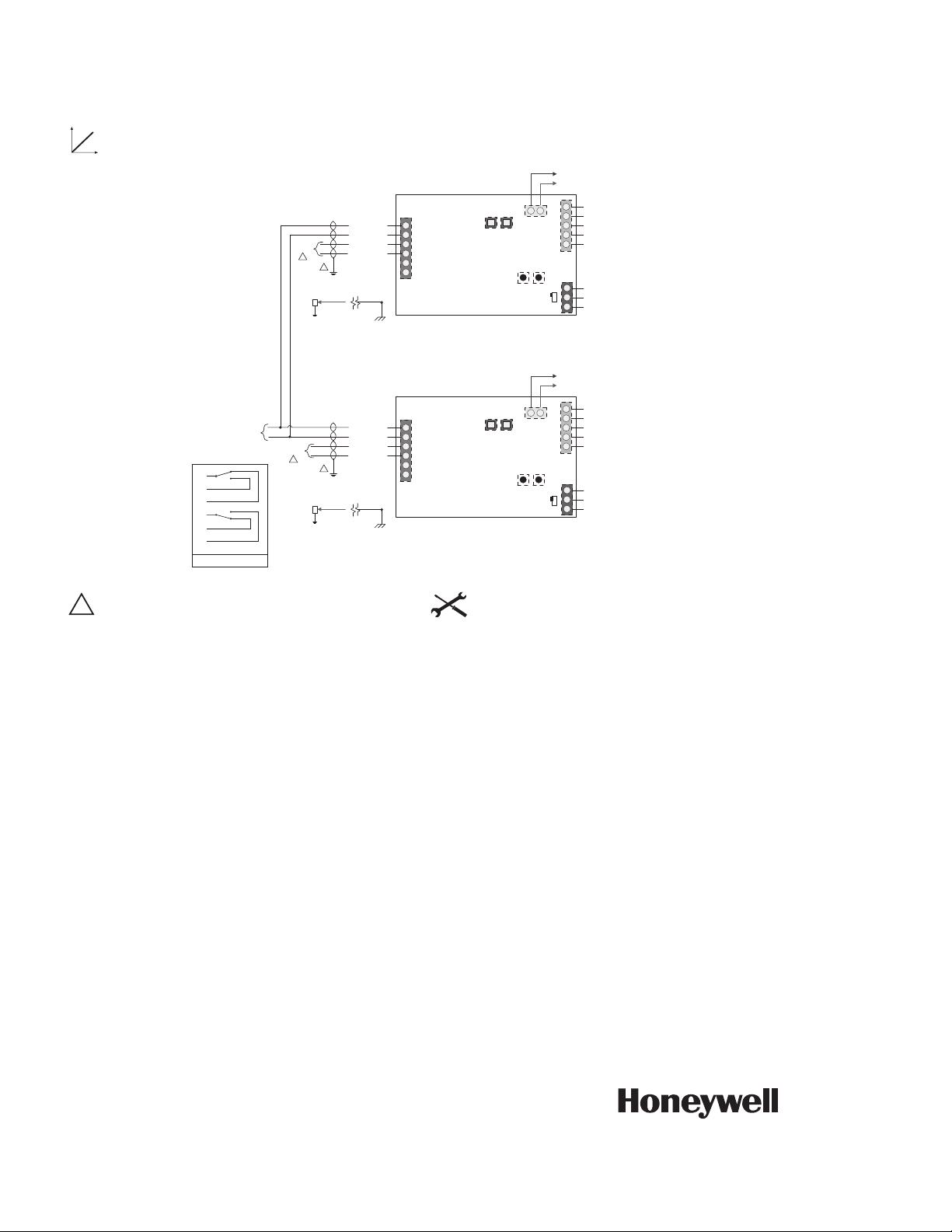
MBP...9, B
INSTALLATION NOTES
• Observe class 1 and class 2 wiring restrictions.
• Transformer sizing = MBP actuator draw X 1.25
(safety margin)
24 VAC Transformer
Line
Volts
G Ground
1 Common
3 Open
4 Closed
5
6
7
HTR
A
B
C
D
E
F
LS3
A-C
(Open Indication)
LS4
D-F
(Closed Indication)
Contact Rating: 5A 250 VAC Max.
MBP...9, B
G Ground
1 Common
3 Open
4 Closed
5
6
7
HTR
A
B
C
D
E
F
LS3
A-C
(Open Indication)
LS4
D-F
(Closed Indication)
Contact Rating: 5A 250 VAC Max.
MBP...9, B
K1
Open
Close
K1-B
K1-A
Actuator A
Actuator B
G
G
INSTALLATION NOTES
• Isolation relays must be used in parallel connection of multiple actuators
using a common control signal input.
• "H" (L2) cannot be connected to terminal #3 and #4 simultaneously.
• Required: Terminal #7 needs to be field wired to enable heater circuit.
Proportional, Multiple Wiring, 24V
MBP...9, B
5
┴
2
9
8
0
3
2
┴
/
-
y
y
y
y
y
y
y
C
y
k
)
)
)
T
5
┴
2
9
8
0
3
2
┴
/
-
y
y
y
y
y
y
y
C
y
k
)
)
)
T
B
A
n
n
33
Each actuator should be powered by a
single, isolated control transformer.
MBP...9, B
INSTALLATION NOTES
• Observe class 1 and class 2 wiring restrictions.
• Transformer sizing = MBP actuator draw X 1.25 (safety margin)
24V AC/DC Transformer
33
Line
Vol ts
Open
Close
G
G Ground
1 Common
3 Open
4 C lo se d
Connect to #1 for fully
5
open indication
Connect to #1 for fully
6
closed indication
7
HTR
A
LS3
B
(Open Indication)
A-C
C
D
LS4
E
(Closed Indication)
D-F
F
Contact Rating: 5A 250 VAC Max.
SY2…5-24
Fig. 23. Wiring for Wiring for MBP6...9,B actuators.
A
LS3
B
A-C
(Open Indication)
C
D
LS4
E
(Closed Indication)
D-F
F
Contact Rating: 5A 250 VAC Max.
SY2…5-24MFT
31-00191EF—02 26
Control Signa
Actuator
PC Tool
Service Jack
Not Used -
Not Used -
Not Used -
Not Used -
Y
1
┴
U
Address
Adaptio
C1
C2
Y1 Y2
PE
Actuator
PC Tool
Service Jack
Y
1
┴
U
Address
Adaptio
C1
C2
Y1 Y2
PE
Control Signal (+
Control Signal (-
Feedbac
Feedbac
36
Feedback Signal (+)
Feedback Signal (-
36
35
G
Control Signal (+
Control Signal (-
Feedback Signal (+)
Feedback Signal (-
35
G
Fig. 24. Wiring for MBP7...9,B.
SYx-24MF
SYx-24MF
A
Internal Use Onl
B
Internal Use Onl
1
Internal Use Onl
Internal Use Onl
Internal Use Onl
Power Supply Com
Power Supply Hot
~/+
Internal Use Onl
Internal Use Onl
1
Internal Use Onl
A
Internal Use Onl
B
Internal Use Onl
1
Internal Use Onl
Internal Use Onl
Internal Use Onl
Power Supply Com
Power Supply Hot
~/+
Internal Use Onl
Internal Use Onl
1
Internal Use Onl
24V AC/D
33
24V AC/D
33
Page 27

VH2, VH3, VH4, VH5, VH6, VH7, VH8 ANSI 150 CLASS HIGH PERFORMANCE BUTTERFLY VALVES
120V AC/DC
On/Off
G Ground
1 Common
3 Open
4 C lo se d
5
Connect to #1 for fully
open indication
6
Connect to #1 for fully
closed indication
7
120V or 230V AC/DC
G
Open
Close
N L1
H L2
HTR
A
B
C
D
E
F
LS3
A-C
(Open Indication)
LS4
D-F
(Closed Indication)
Contact Rating: 5A 250 VAC Max.
SY2…12-120V or 230V
MBP...C, D, E
INSTALLATION NOTES
• Observe class 1 and class 2 wiring restrictions.
• Transformer sizing = MBP actuator draw X 1.25 (safety margin)
G Ground
1
Common
3 Open
4 Closed
5
6
7
HTR
A
B
C
D
E
F
LS3
A-C
(Open Indication)
LS4
D-F
(Closed Indication)
Contact Rating: 5A 250 VAC Max.
G Ground
1 Common
3 Open
4 Closed
5
6
7
HTR
A
B
C
D
E
F
LS3
A-C
(Open Indication)
LS4
D-F
(Closed Indication)
Contact Rating: 5A 250 VAC Max.
MBP, C, D, E
MBP...C, D, E
Open
Close
K1-B
K1-A
Actuator A
Actuator B
120 VAC
N L1
H L2
G
G
K1
INSTALLATION NOTES
• Isolation relays must be used in parallel connection
of multiple actuators using a common control signal input.
• "H" (L2) cannot be connected to terminal
#3 and #4 simultaneously.
• Required: Terminal #7 needs to be field wired
to enable heater circuit.
Fig. 25. Wiring for MBP6...D,E,F,G.
27 31-00191EF—02
Page 28
VH2, VH3, VH4, VH5, VH6, VH7, VH8 ANSI 150 CLASS HIGH PERFORMANCE BUTTERFLY VALVES
Proportional, Multiple Wiring, 120V
MBP...C, D, E
V
V
┴
5
2
9
810
3
2
y
y
y
y
y
y
y
y
k
)
)
)
T
n
T
L
V
V
5
2
9
8
0
3
2
y
y
y
y
y
y
y
y
k
)
)
)
T
n
T
L
A
B
33
Each actuator should be powered by a single,
isolated control transformer.
INSTALLATION NOTES
• Observe class 1 and class 2 wiring restrictions.
• Transformer sizing = MBP actuator draw X 1.25 (safety margin)
Power Supply Com – 120
Power Supply Hot – 120
A
B
1
Address Adaptio
Y1
Y2
Power Supply Com – 120
Power Supply Hot – 120
A
B
1
Address Adaptio
Y1
Y2
1
Internal Use Onl
Internal Use Onl
Internal Use Onl
Internal Use Onl
Internal Use Onl
Internal Use Onl
Internal Use Onl
Internal Use Onl
Internal Use Onl
Internal Use Onl
Internal Use Onl
Internal Use Onl
Internal Use Onl
Internal Use Onl
Internal Use Onl
Internal Use Onl
Control Signa
A
LS3
B
A-C
(Open Indication)
C
D
LS4
E
(Closed Indication)
D-F
F
Contact Rating: 5A 250 VAC Max.
MBP...C, D, E
Feedbac
Feedbac
36
SYx-120MF
SYx-230MF
SYx-120MF
SYx-230MF
N
N
PC Tool
Service Jack
PC Tool
Service Jack
Not Used -
Not Used -
Not Used -
Not Used -
Y
1
U
┴
C1
C2
PE
Actuator
Y
1
┴
U
┴
C1
C2
PE
Actuator
Control Signal (+
Control Signal (-
Feedback Signal (+)
36
Feedback Signal (-
35
G
Control Signal (+
Control Signal (-
Feedback Signal (+)
Feedback Signal (-
35
G
By using this Honeywell literature, you agree that Honeywell will have no liability for any damages arising out of your use or
modification to, the literature. You will defend and indemnify Honeywell, its affiliates and subsidiaries, from and against any
liability, cost, or damages, including attorneys’ fees, arising out of, or resulting from, any modification to the literature by you.
Honeywell Building Technologies
In the U.S.:
Honeywell
Fig. 26. Wiring for MBP7...D,E,F,G.
® U.S. Registered Trademark
© 2019 Honeywell International Inc.
31-00191EF—02 M.S. Rev. 07-19
Printed in United States
Page 29

Vannes papillon haute performance
VH2 VH3, VH4, VH5, VH6, VH7, VH8
ANSI de classe 150
DONNÉES SUR LE PRODUIT
deux états (tout ou rien) jusqu’à 50 lb/po² dans les
systèmes de CVC
Vannes à 2 voies (VH2)
• Tailles de 2 à 24 po avec raccords à oreilles ANSI de
classe 125/150
• Caractéristiques de débit à pourcentages égaux
modifiés
• Système de sécurité à ressort sur les modèles de 2 et
4 po et système électronique en option sur les modèles
de 5 et 6 po.
• Actionneurs NEMA 2 disponibles sur les vannes de 2 à
4 po; actionneurs NEMA 4 X disponibles sur les vannes
de 5 à 24 po
Ensembles de vannes à trois voies
CARACTÉRISTIQUES
Tous les modèles
• ANSI classe 150
• Disques en acier inoxydable 316
• Corps de vanne en acier ordinaire
• Tige de vanne en acier inoxydable
• Siège de vanne en RTFE
• Aucune fuite au taux nominal de fermeture
• Vitesse maximale de 32 pi/s
• Taux nominal de fermeture de 150 lb/po² pour tous les
diamètres
• Bride de fixation d’actionneur ISO 5211
• Disponible avec interfaces d’actionneur électrique
installées en usine à deux positions : commande
flottante (trois états) ou à modulation (2-10 V c.c.)
• Contournement manuel sur tous les modèles
• Pour eau chaude, refroidie ou de condensation avec un
maximum de 60 % de glycol; commande de vapeur à
(VH3, 4, 5, 6, 7, 8)
• Tailles de 2 à 16 po avec raccords à oreilles ANSI de
classe 125/150.
• Commande de mélange (VH3,4,5) ou de dérivation
(VH6,7,8).
• Caractéristique de débit linéaire modifié.
• Raccord en T standard en fonte compris.
• Nombreuses configurations de ports convenant à
différentes applications.
• Dispositif de sécurité électronique disponible sur les
modèles de 2 à 3 po
• Actionneurs NEMA 2 disponibles sur les vannes de 3 po
et moins; actionneurs NEMA 4 X disponibles sur les
vannes de 4 po à 16 po
Table des matières
CARACTÉRISTIQUES ................................................................. 1
SPÉCIFICATIONS ........................................................................ 2
PLANS DIMENSIONNELS ...................................................... 5
SPÉCIFICATIONS DE L’ACTIONNEUR ................................ 13
CONFIGURATIONS DE VANNES À 3 VOIES ..................... 16
INSTALLATION ............................................................................ 18
INSTALLATION ÉLECTRIQUE ............................................... 22
Page 30

VANNES PAPILLON HAUTE PERFORMANCE VH2 VH3, VH4, VH5, VH6, VH7, VH8 ANSI DE CLASSE 150
SPÉCIFICATIONS
REMARQUE : Toutes les spécifications étaient précises au
moment de la publication. Honeywell réserve
le droit d’améliorer ou d’abandonner des
produits sans préavis. Pour obtenir la
documentation technique la plus récente,
veuillez consulter le site Web
http://
Modèles : Voir le Tableau 1
Dimensions : Voir les figures 1 à 8
Montage : ASME/ANSI, classe 150
Types de corps :
Vannes papillon haute performance à deux ou trois voies
ANSI de classe 150
Dimensions du corps :
Vannes à 2 voies : 2 à 24 po
Vannes à 3 voies : 2 à 16 po
Caractéristiques de débit :
Vannes à 2 voies : Pourcentage égal modifié,
unidirectionnel
Vannes à 3 voies : Débit linéaire modifié, unidirectionnel
Pression statique nominale du corps (maximum) :
285 lb/po² à 100 °F (1965 kPa à 38 °C)
Pression nominale de fermeture (différentiel
maximum) :
150 lb/po²
Liquides contrôlés : Eau chaude ou refroidie contenant
jusqu’à 60 % de glycol; vapeur jusqu’à 50 lb/po²
Plage de température des liquides : -30 à 204 °C
(-22 à 400 °F)
Vitesse maximale : 9,8m/s (32pi/s)
Matériaux :
Corps : Acier ordinaire à oreilles pleines
Disque : Acier inoxydable 316
Tige : Acier inoxydable 17-4 PH
Siège : RTFE
Presse-garniture : TFE
Roulements : PTFE renforcé à la fibre de verre
Approbations et normes :
Fermeture : Aucune fuite jusqu’au taux nominal de
fermeture.
Les actionneurs sur les vannes à 2 voies de 6 po et moins et
sur les vannes à 3 voies de 5 po et moins : cULus, CE
Actionneurs sur les vannes à 2 voies de 8 po et plus et sur
les vannes à 3 voies de 5 po et plus : cCSAus, CE
Caractéristiques nominales d’actionneur :
Voir le Tableau 6
Accessoires :
MB-NSR-SWITCH : Interrupteur auxiliaire NSR DCA
MB-NSR-N4HEAT : Trousse de chauffage NSR NEMA4
DCA (doit être commandée avec la vanne, installée à
l’usine)
MB-SR-N4HEAT : Trousse de chauffage SR NEMA4 DCA
(doit être commandée avec la vanne, installée à l’usine)
31-00191EF—02 2
Page 31

VANNES PAPILLON HAUTE PERFORMANCE VH2 VH3, VH4, VH5, VH6, VH7, VH8 ANSI DE CLASSE 150
Tableau 1. Sélection de modèle de vanne papillon.
corps
Vanne
Type de
papillon
raccordement
Vanne, à oreilles (papillon)
V
Haute Performance ANSI 150
H
Motif de
2
vanne
Diamètre de
2 voies
Ten sio n
de l’actionneur
Signal de commande
d’actionneur
sécurité
Fonction de
du contacteur
Caractéristiques
Tension/rétroaction
nominales NEMA
3
Configurations de robinets de mélange à 3 voies (voir la Fig. 9)
4
5
6
Configurations de robinets de dérivation à 3 voies (voir la Fig. 9)
7
8
2 po (DN 50)
F
2,5 po (DN 65)
G
3 po (DN 80)
H
4 po (DN 100)
J
5 po (DN 125)
K
6 po (DN 150)
L
8 po (DN 200)
M
10 po (DN 250)
N
12 po (DN 300)
P
14 po (DN 350)
R
16 po (DN 400)
S
18 po (DN 450) à 2 voies seulement
T
20 po (DN 500) à 2 voies seulement
U
24 po (DN 600) à 2 voies seulement
V
Flottant/deux positions (SPDT)
6
À modulation analogique (0) 2-10 V c.c.
7
Deux positions (SPST)
8
24 V c.a./V c.c.
L
120 V c.a.
H
24-240 V c.a./24-125 V c.c.
U
Maintien de position en cas de panne
P
Ressort de rappel au port A (maître) à sécurité intrinsèque en position ouverte
S
Ressort de rappel au port A (maître) à sécurité intrinsèque en position fermée
T
Dispositif de sécurité électronique (position fermée par défaut, modifiable sur place)
E
Aucune rétroaction
N
Rétroaction analogique
F
Interrupteurs auxiliaires intégrés
S
Rétroaction analogique et interrupteurs auxiliaires
B
2
4
H
VH2H 7 L P F 2
Description
NEMA 2
NEMA 4X
NEMA 4X (avec réchauffeur)
EXEMPLE : VANNE PAPILLON HAUTE PERFORMANCE 2 VOIES, 3 PO ,ANSI DE CLASSE 150,
CV228, FERMETURE 285 LB/PO², 24 V C.A., 2-10 V C.C., 150 S, MAINTIEN EN CAS DE
PANNE, RÉTROACTION, NEMA2, (COMPREND L’ACTIONNEUR MBP7L4F2/U)
3 31-00191EF—02
Page 32

VANNES PAPILLON HAUTE PERFORMANCE VH2 VH3, VH4, VH5, VH6, VH7, VH8 ANSI DE CLASSE 150
Tableau 2. Sélection de modèle d’actionneur de remplacement de vanne papillon.
Type
À sécurité
Régulatio n
intrinsèque
Type
Rétroaction
d'actionneur
Alimentation
MB Moteur de vanne papillon
S Système de sécurité à ressort
E Système de sécurité électronique
P Maintien de position en cas de panne
6 À flotteur/deux positions (SPDT)
7 À modulation analogique (0) 2-10 V c.c.
8 Deux positions (SPST)
24 V c.a./c.c.
L
24-240 V c.a./24-125 V c.c.
U
120 V c.a.
H
1 SR 180 lb-po
2 NSR 180 lb-po
3 SR 180 lb-po
A NSR 180 lb-po
4 EFS/FIP 360 lb-po (VR à 2 voies)
R EFS/FIP 360 lb-po (VH et VR à 3 voies)
5 EFS/FIP 800 lb-po
6 EFS/FIP 1400 lb-po
7 EFS/FIP 1400 lb-po
8 EFS/FIP 1400 lb-po
9 FIP 3540 lb-po
B FIP 4425 lb-po
C FIP 5755 lb-po
D FIP 8850 lb-po
E FIP 13275 lb-po
F FIP 17700 lb-po
G FIP 22125 lb-po
H FIP 26550 lb-po
N Aucune rétroaction
F Rétroaction analogique
S Interrupteurs auxiliaires intégrés
B Rétroaction analogique et interrupteurs auxiliaires
MB S 8 U 1 N 2
Nema
Description
2 NEMA 2
4 NEMA 4X
H NEMA 4X (avec réchauffeur)
EXEMPLE : ACTIONNEUR DE VANNE PAPILLON POUR SÉRIES VR ET VH, RESSORT DE RETOUR, 2 POSITIONS,
24-240 V C.A., 180 LB-PO, NEMA2.
REMARQUE : Les tableaux ci-dessus sont destinés à expliquer la signification du système de numérotation de la vanne
papillon et de l’actionneur. Il ne s’agit pas d’un outil de configuration du produit. Seuls les numéros de pièce
compris dans les catalogues de prix Honeywell peuvent être commandés. Veuillez vous reporter au
cpq.honeywell.com pour connaître les configurations disponibles.
31-00191EF—02 4
Page 33

VANNES PAPILLON HAUTE PERFORMANCE VH2 VH3, VH4, VH5, VH6, VH7, VH8 ANSI DE CLASSE 150
E
D
BC
A
PLANS DIMENSIONNELS
Diam. Dimensions, mm (po)
po DN A B C D E
2 50 45,0 (1,77) 215,6 (8,49) 215,6 (8,49) 362,0 (14,25) 146,6) (5,77)
2,5 65 48,3 (1,90) 215,6 (8,49) 215,6 (8,49) 362,0 (14,25) 165,6 (6,52)
3 80 48,3 (1,90) 215,6 (8,49) 215,6 (8,49) 380,7(14,99) 178,3 (7,02)
4 100 54,6 (2,15) 215,6 (8,49) 215,6 (8,49) 400,1 (15,75) 216,4 (8,52)
Fig. 1. Vannes à 2 voies avec actionneurs MBP...R.
5 31-00191EF—02
Page 34

VANNES PAPILLON HAUTE PERFORMANCE VH2 VH3, VH4, VH5, VH6, VH7, VH8 ANSI DE CLASSE 150
A
D
BC
E
Diam. Dimensions, mm (po)
poDNABCDE
2 50 45,0 (1,77) 36,1 (1,42) 194,1 (7,64) 233,9 (9,21) 146,6 (5,77)
2,5 65 48,3 (1,90) 36,1 (1,42) 194,1 (7,64) 233,9 (9,21) 165,6 (6,52)
3 80 1,90 (48,3) 36,1 (1,42) 194,1 (7,64) 252,7 (9,95) 178,3 (7,02)
4 100 54,6 (2,15) 36,1 (1,42) 194,1 (7,64) 339,3 (13,36) 216,4 (8,52)
Fig. 2. Vannes à 2 voies avec actionneurs tandem MBS...1.
31-00191EF—02 6
Page 35

VANNES PAPILLON HAUTE PERFORMANCE VH2 VH3, VH4, VH5, VH6, VH7, VH8 ANSI DE CLASSE 150
E
D
BC
A
Diam. Dimensions, mm (po)
po DN A B C D E
5 125 58,7 (2,31) 61,0 (2,40) 242,6 (9,55) 482,1 (18,98) 247,9 (9,76)
6 150 58,7 (2,31) 61,0 (2,40) 242,6 (9,55) 495,8 (19,52) 273,3 (10,76)
Fig. 3. Vannes à 2 voies avec actionneurs MBE...6.
7 31-00191EF—02
Page 36

VANNES PAPILLON HAUTE PERFORMANCE VH2 VH3, VH4, VH5, VH6, VH7, VH8 ANSI DE CLASSE 150
E
D
BC
A
Diam. Dimensions, mm (po)
poDNABCDE
8 200 63,0 (2,48) 4111,8 (4,40) 181,1 (7,13) 587,8 (23,14) 334,5 (13,17)
10 250 71,4 (2,81) 111,8 (4,40) 181,1 (7,13) 606,8 (23,89) 403,6 (15,89)
12 300 81,8 (3,22) 111,8 (4,40) 181,1 (7,13) 698,2 (27,49) 472,9 (18,62)
14 350 81,8 (3,22) 111,8 (4,40) 181,1 (7,13) 713,7 (28,10) 527,1 (20,75)
16 400 107,2 (4,22) 108,5 (4,27) 212,1 (8,35) 841,5 (33,13) 581,4 (22,89)
18 450 119,6 (4,71) 108,5 (4,27) 212,1 (8,35) 874,8 (34,4 634,0 (24,96)
20 500 133,4 (5,25) 218,2 (8,59) 182,9 (7,20) 1049,5 (41,32) 683,0 (26,89)
24 600 161,5 (6,36) 218,2 (8,59) 182,9 (7,20) 1103,4 (43,44) 794,5 (31,28)
Fig. 4. Vannes à 2 voies avec actionneurs MBP...9, B, D, F, G.
31-00191EF—02 8
Page 37

VANNES PAPILLON HAUTE PERFORMANCE VH2 VH3, VH4, VH5, VH6, VH7, VH8 ANSI DE CLASSE 150
B
D
CA
Diam. Dimensions, mm (po)
poDNABCD
2 50 114,3 (4,50) 158,2 (6,23) 172,2 (6,78) 298,5 (11,75)
2,5 65 127,0 (5,00) 175,0 (6,89) 187,2 (7,37) 362,0 (14,25)
3 80 139,7 (5,50) 188,7 (7,43) 200,2 (7,88) 317,5 (12,50)
Fig. 5. Vannes à 3 voies avec actionneurs MBP...R.
9 31-00191EF—02
Page 38

VANNES PAPILLON HAUTE PERFORMANCE VH2 VH3, VH4, VH5, VH6, VH7, VH8 ANSI DE CLASSE 150
D
BCA
Diam. Dimensions, mm (po)
poDNABCD
2 50 114,3 (4,50) 158,2 (6,23) 172,5 (6,79) 316,7 (12,47)
2,5 65 127,0 (5,00) 175,0 (6,89) 186,9 (7,36) 244,9 (9,64)
3 80 139,7 (5,50) 188,7 (7,43) 200,4 (7,89) 335,8 (13,22)
Fig. 6. Vannes à 3 voies avec actionneurs MBE...R.
31-00191EF—02 10
Page 39

VANNES PAPILLON HAUTE PERFORMANCE VH2 VH3, VH4, VH5, VH6, VH7, VH8 ANSI DE CLASSE 150
D
BCA
Diam. Dimensions, mm (po)
po DN A B C D
4 100 165,1 (6,50) 218,9 (8,62) 253,0 (9,96) 406,9 (16,02)
Fig. 7. Vannes à 3 voies avec actionneurs MBP...6.
11 31-00191EF—02
Page 40

VANNES PAPILLON HAUTE PERFORMANCE VH2 VH3, VH4, VH5, VH6, VH7, VH8 ANSI DE CLASSE 150
D
BCA
Diam. Dimensions, mm (po)
poDNABCD
5 125 7,50 (191) 10,00 (254) 13,50 (343) 21,00 (533)
6 150 203 (8,00) 262 (10,30) 343 (13,50) 594 (23,40)
8 200 228,6 (9,00) 292,1 (11,50) 372,1 (14,65) 587,8 (23,14)
10 250 279,4 (11,00) 350,8 (13,81) 426,7 (16,80) 607,1 (23,90)
12 300 304,8 (12,00) 386,6 (15,22) 457,5 (18,01) 651,5 (25,65)
14 350 355,6 (14,00) 447,5 (17,62) 510,0 (20,08) 757,9 (29,84)
16 400 381,0 (15,00) 482,6 (19,00) 540,3 (21,27) 794,8 (31,29)
Fig. 8. Vannes à 3 voies avec actionneurs MBP...9, B, D, E.
31-00191EF—02 12
Page 41

VANNES PAPILLON HAUTE PERFORMANCE VH2 VH3, VH4, VH5, VH6, VH7, VH8 ANSI DE CLASSE 150
SPÉCIFICATIONS DE L’ACTIONNEUR
Tableau 3. Actionneurs utilisés sur les ensembles à 2 voies
Montage Actionneur Montage Actionneur Montage Actionneur
VH2F6LPN2/M MBP6LRN2/U VH2H7LTF2/M MBS7L1F2/U VH2N6LPSH/M MBP6L9SH/U
VH2F7LPF2/M MBP7LRF2/U VH2H8LSN2/M MBS8L1N2/U VH2N7LPBH/M MBP7L9SH/U
VH2F7LSF2/M MBS7L1F2/U VH2H8LTN2/M MBS8L1N2/U VH2P6LPSH/M MBP6L9SH/U
VH2F7LTF2/M MBS7L1F2/U VH2J6LPN2/M MBP6LRN2/U VH2P7LPBH/M MBP7L9SH/U
VH2F8LSN2/M MBS8L1N2/U VH2J7LPF2/M MBP7LRF2/U VH2R6LPSH/M MBP6LBSH/U
VH2F8LTN2/M MBS8L1N2/U VH2J7LSF2/M MBS7L1F2/U VH2R7LPBH/M MBP7LBBH/U
VH2G6LPN2/M MBP6LRN2/U VH2J7LTF2/M MBS7L1F2/U VH2S6HPSH/M MBP6HDSH/U
VH2G7LPF2/M MBP7LRF2/U VH2J8LSN2/M MBS8L1N2/U VH2S7HPBH/M MBP7HDBH/U
VH2G7LSF2/M MBS7L1F2/U VH2J8LTN2/M MBS8L1N2/U VH2T6HPSH/M MBP6HDSH/U
VH2G7LTF2/M MBS7L1F2/U VH2K6UESH/M MBE6U6SH/U VH2T7HPBH/M MBP7HDBH/U
VH2G8LSN2/M MBS8L1N2/U VH2K7UEBH/M MBE7U6BH/U VH2U6HPSH/M MBP6HFSH/U
VH2G8LTN2/M MBS8L1N2/U VH2L6UESH/M MBE6U6SH/U VH2U7HPBH/M MBP7HFBH/U
VH2H6LPN2/M MBP6LRN2/U VH2L7UEBH/M MBE7U6BH/U VH2V6HPSH/M MBP6HGSH/U
VH2H7LPF2/M MBP7LRF2/U VH2M6LPSH/M MBP6L9SH/U VH2V7HPBH/M MBP7HGBH/U
VH2H7LSF2/M MBS7L1F2/U VH2M7LPBH/M MBP7L9SH/U
Montage Actionneur Montage Actionneur Montage Actionneur
VH3F6LPN2/M MBP6LRN2/U VH4F6LPN2/M MBP6LRN2/U VH5F6LPN2/M MBP6LRN2/U
VH3F7LEF2/M MBE7LRF2/U VH4F7LEF2/M MBE7LRF2/U VH5F7LEF2/M MBE7LRF2/U
VH3F7LPF2/M MBP7LRF2/U VH4F7LPF2/M MBP7LRF2/U VH5F7LPF2/M MBP7LRF2/U
VH3F8LEN2/M MBE6LRN2/U VH4F8LEN2/M MBE6LRN2/U VH5F8LEN2/M MBE6LRN2/U
VH3G6LPN2/M MBP6LRN2/U VH4G6LPN2/M MBP6LRN2/U VH5G6LPN2/M MBP6LRN2/U
VH3G7LEF2/M MBE7LRF2/U VH4G7LEF2/M MBE7LRF2/U VH5G7LEF2/M MBE7LRF2/U
VH3G7LPF2/M MBP7LRF2/U VH4G7LPF2/M MBP7LRF2/U VH5G7LPF2/M MBP7LRF2/U
VH3G8LEN2/M MBE6LRN2/U VH4G8LEN2/M MBE6LRN2/U VH5G8LEN2/M MBE6LRN2/U
VH3H6LPN2/M MBP6LRN2/U VH4H6LPN2/M MBP6LRN2/U VH5H6LPN2/M MBP6LRN2/U
VH3H7LEF2/M MBE7LRF2/U VH4H7LEF2/M MBE7LRF2/U VH5H7LEF2/M MBE7LRF2/U
VH3H7LPF2/M MBP7LRF2/U VH4H7LPF2/M MBP7LRF2/U VH5H7LPF2/M MBP7LRF2/U
VH3H8LEN2/M MBE6LRN2/U VH4H8LEN2/M MBE6LRN2/U VH5H8LEN2/M MBE6LRN2/U
VH3J6UPSH/M MBP6U6SH/U VH4J6UPSH/M MBP6U6SH/U VH5J6UPSH/M MBP6U6SH/U
VH3J7UPBH/M MBP7U6BH/U VH4J7UPBH/M MBP7U6BH/U VH5J7UPBH/M MBP7U6BH/U
VH3K6UPSH/M MBP6L9SH/U VH4K6UPSH/M MBP6L9SH/U VH5K6UPSH/M MBP6L9SH/U
VH3K7UPBH/M MBP7L9SH/U VH4K7UPBH/M MBP7L9SH/U VH5K7UPBH/M MBP7L9SH/U
VH3L6LPSH/M MBP6L9SH/U VH4L6LPSH/M MBP6L9SH/U VH5L6LPSH/M MBP6L9SH/U
VH3L7LPBH/M MBP7L9SH/U VH4L7LPBH/M MBP7L9SH/U VH5L7LPBH/M MBP7L9SH/U
VH3M6LPSH/M MBP6L9SH/U VH4M6LPSH/M MBP6L9SH/U VH5M6LPSH/M MBP6L9SH/U
VH3M7LPBH/M MBP7L9SH/U VH4M7LPBH/M MBP7L9SH/U VH5M7LPBH/M MBP7L9SH/U
VH3N6LPSH/M MBP6L9SH/U VH4N6LPSH/M MBP6L9SH/U VH5N6LPSH/M MBP6L9SH/U
VH3N7LPBH/M MBP7L9SH/U VH4N7LPBH/M MBP7L9SH/U VH5N7LPBH/M MBP7L9SH/U
VH3P6LPSH/M MBP6LBSH/U VH4P6LPSH/M MBP6LBSH/U VH5P6LPSH/M MBP6LBSH/U
VH3P7LPBH/M MBP7LBBH/U VH4P7LPBH/M MBP7LBBH/U VH5P7LPBH/M MBP7LBBH/U
VH3R6HPSH/M MBP6HDSH/U VH4R6HPSH/M MBP6HDSH/U VH5R6HPSH/M MBP6HDSH/U
VH3R7HPBH/M MBP7HDBH/U VH4R7HPBH/M MBP7HDBH/U VH5R7HPBH/M MBP7HDBH/U
VH3S6HPSH/M MBP6HDSH/U VH4S6HPSH/M MBP6HDSH/U VH5S6HPSH/M MBP6HDSH/U
VH3S7HPBH/M MBP7HDBH/U VH4S7HPBH/M MBP7HDBH/U VH5S7HPBH/M MBP7HDBH/U
Tableau 4. Actionneurs utilisés sur les ensembles de mélange à 3 voies.
13 31-00191EF—02
Page 42

VANNES PAPILLON HAUTE PERFORMANCE VH2 VH3, VH4, VH5, VH6, VH7, VH8 ANSI DE CLASSE 150
Tableau 5. Actionneurs utilisés sur les ensembles de dérivation à 3 voies.
Montage Actionneur Montage Actionneur Montage Actionneur
VH6F6LPN2/M MBP6LRN2/U VH7F6LPN2/M MBP6LRN2/U VH8F6LPN2/M MBP6LRN2/U
VH6F7LEF2/M MBE7LRF2/U VH7F7LEF2/M MBE7LRF2/U VH8F7LEF2/M MBE7LRF2/U
VH6F7LPF2/M MBP7LRF2/U VH7F7LPF2/M MBP7LRF2/U VH8F7LPF2/M MBP7LRF2/U
VH6F8LEN2/M MBE6LRN2/U VH7F8LEN2/M MBE6LRN2/U VH8F8LEN2/M MBE6LRN2/U
VH6G6LPN2/M MBP6LRN2/U VH7G6LPN2/M MBP6LRN2/U VH8G6LPN2/M MBP6LRN2/U
VH6G7LEF2/M MBE7LRF2/U VH7G7LEF2/M MBE7LRF2/U VH8G7LEF2/M MBE7LRF2/U
VH6G7LPF2/M MBP7LRF2/U VH7G7LPF2/M MBP7LRF2/U VH8G7LPF2/M MBP7LRF2/U
VH6G8LEN2/M MBE6LRN2/U VH7G8LEN2/M MBE6LRN2/U VH8G8LEN2/M MBE6LRN2/U
VH6H6LPN2/M MBP6LRN2/U VH7H6LPN2/M MBP6LRN2/U VH8H6LPN2/M MBP6LRN2/U
VH6H7LEF2/M MBE7LRF2/U VH7H7LEF2/M MBE7LRF2/U VH8H7LEF2/M MBE7LRF2/U
VH6H7LPF2/M MBP7LRF2/U VH7H7LPF2/M MBP7LRF2/U VH8H7LPF2/M MBP7LRF2/U
VH6H8LEN2/M MBE6LRN2/U VH7H8LEN2/M MBE6LRN2/U VH8H8LEN2/M MBE6LRN2/U
VH6J6UPSH/M MBP6U6SH/U VH7J6UPSH/M MBP6U6SH/U VH8J6UPSH/M MBP6U6SH/U
VH6J7UPBH/M MBP7U6BH/U VH7J7UPBH/M MBP7U6BH/U VH8J7UPBH/M MBP7U6BH/U
VH6K6UPSH/M MBP6L9SH/U VH7K6UPSH/M MBP6L9SH/U VH8K6UPSH/M MBP6L9SH/U
VH6K7UPBH/M MBP7L9SH/U VH7K7UPBH/M MBP7L9SH/U VH8K7UPBH/M MBP7L9SH/U
VH6L6LPSH/M MBP6L9SH/U VH7L6LPSH/M MBP6L9SH/U VH8L6LPSH/M MBP6L9SH/U
VH6L7LPBH/M MBP7L9SH/U VH7L7LPBH/M MBP7L9SH/U VH8L7LPBH/M MBP7L9SH/U
VH6M6LPSH/M MBP6L9SH/U VH7M6LPSH/M MBP6L9SH/U VH8M6LPSH/M MBP6L9SH/U
VH6M7LPBH/M MBP7L9SH/U VH7M7LPBH/M MBP7L9SH/U VH8M7LPBH/M MBP7L9SH/U
VH6N6LPSH/M MBP6L9SH/U VH7N6LPSH/M MBP6L9SH/U VH8N6LPSH/M MBP6L9SH/U
VH6N7LPBH/M MBP7L9SH/U VH7N7LPBH/M MBP7L9SH/U VH8N7LPBH/M MBP7L9SH/U
VH6P6LPSH/M MBP6LBSH/U VH7P6LPSH/M MBP6LBSH/U VH8P6LPSH/M MBP6LBSH/U
VH6P7LPBH/M MBP7LBBH/U VH7P7LPBH/M MBP7LBBH/U VH8P7LPBH/M MBP7LBBH/U
VH6R6HPSH/M MBP6HDSH/U VH7R6HPSH/M MBP6HDSH/U VH8R6HPSH/M MBP6HDSH/U
VH6R7HPBH/M MBP7HDBH/U VH7R7HPBH/M MBP7HDBH/U VH8R7HPBH/M MBP7HDBH/U
VH6S6HPSH/M MBP6HDSH/U VH7S6HPSH/M MBP6HDSH/U VH8S6HPSH/M MBP6HDSH/U
VH6S7HPBH/M MBP7HDBH/U VH7S7HPBH/M MBP7HDBH/U VH8S7HPBH/M MBP7HDBH/U
31-00191EF—02 14
Page 43

VANNES PAPILLON HAUTE PERFORMANCE VH2 VH3, VH4, VH5, VH6, VH7, VH8 ANSI DE CLASSE 150
Tableau 6. Données de spécification de l’actionneur.
À sécurité
intrinsèque
Modèle de
l’actionneur Couple
MBS8L1N2/U
MBS7L1F2/U Modulation Fig. 17
MBP6LRN2/U
MBP7LRF2/U Modulation 7 VA (classe 2) Fig. 17
MBE6LRN2/U
MBE7LRF2/U Modulation Fig. 19
MBP6U6SH/U
MBP7U6BH/U Modulation Fig. 21
MBE6U6SH/U
MBE7U6BH/U Modulation Fig. 21
MBP6L9SH/U
MBP7L9SH/U Modulation Fig. 24
MBP6LBSH/U
MBP7LBBH/U Modulation Fig. 24
MBP6HDSH/U
MBP7HDBH/U Modulation 240 VA 59 s Fig. 26
MBP6HESH/U
MBP7HEBH/U Modulation 336 VA 79 s Fig. 26
MBP6HFSH/U
MBP7HFBH/U Modulation 324 VA 65 s Fig. 26
MBP6HGSH/U
MBP7HGBH/U Modulation 360 VA 76 s Fig. 26
180 lb-po
(20 Nm)
360 lb-po
(40 Nm)
360 lb-po
(40 Nm)
1400 lb-po
(160 Nm)
1400 lb-po
(160 Nm)
3540 lb-po
(400 Nm)
4425 lb-po
(500 Nm)
8850 lb-po
(1000 Nm)
13275 lb-po
(1500 Nm)
17700 lb-po
(2000 Nm)
22125 lb-po
(2500 Nm)
Entrées de
commande
2 positions Système de
2 positions;
flottant
2 positions;
flottant
2 positions;
flottant Maintien de
2 positions;
flottant
2 positions
2 positions
2 positions
2 positions 504 VA 51 s Fig. 25
2 positions 360 VA 62 s Fig. 25
2 positions 384 VA 62 s Fig. 25
(Tempori-
sation)
sécurité à
ressort
(< 20 s)
Maintien de
position en
cas de panne
Système de
sécurité
électronique
(35 s)
position en
cas de panne
Système de
sécurité
électronique
(30 s)
Maintien de
position en
cas de panne
Maintien de
position en
cas de panne
Ten sio n
d’alimentation
24 V c.a., ±20 %,
50/60 Hz;
24 V c.c., -
10 %/+20 %
24 V c.a., ±20 %,
50/60 Hz;
24 V c.c., ±10 %
24 V c.a., ±20 %,
50/60 Hz;
24 V c.c., ±10 %
24... 240 V c.a., 20 %/+10 %,
50/60 Hz;
24... 125 V c.c., 20 %/+10 %
24... 240 V c.a., 20 %/+10 %,
50/60 Hz;
24... 125 V c.c., 20 %/+10 %
24 V c.a., ±10 %,
50/60 Hz;
24 V c.c., ±10 %
24 V c.a., ±10 %,
50/60 Hz
Calibrage du
transformateur
10 VA (classe 2)
6 VA (classe 2)
21 VA (classe 2)
20 VA à
24 V c.a./c.c.
(classe 2); 23 VA à
120 V c.a./c.c.;
52 VA à 230 V c.a.
55 VA à
V c.a./c.c.
24
(classe 2); 43 VA à
120 V c.a./c.c.;
68 VA à 230 V c.a.
226 VA
214 VA 26 s
504 VA
Tem pér atu re
ambiante
-30 à 50 °C
(-22 à 122 °F)
-30 à 50 °C
(-22 à 122 °F)
-30 à 50 °C
(-22 à 122 °F)
-30 à 50 °C
(-22 à 122 °F)
-30 à 50 °C
(-22 à 122 °F)
-30 à 65 °C
(-22 à 150 °F)
-30 à 65 °C
(-22 à 150 °F)
Tem por
isation Boîtier
150 s
150 s
150 s
35 s
35 s
20 s
50 s
IP-54,
NEMA 2
IP-54,
NEMA 2
IP-54,
NEMA 2
IP 66/67
NEMA 4X avec
réchauffeur
IP 66/67
NEMA 4X avec
réchauffeur
IP 66/67
NEMA 4X avec
réchauffeur
IP 66/67
NEMA 4X avec
réchauffeur
Interrupt
eur
auxiliaire
2 x SPDT*
2 x SPDT*
2 x SPDT**
2 x SPDT**
Schéma
de
câblage
Fig. 15
Fig. 15
Fig. 18
Fig. 20
Fig. 20
Fig. 23
Fig. 23
Fig. 25
* 3 A résistive (0,5 A inductive) à 250 V c.a., un réglage à 10°, un réglage de 10 à 90°
** 3 A résistive (0,5 A inductive) à 250 V c.a., un réglage à 10°, un réglage à 85°
Tableau 7. Duty Cycle on High Torque Actuators.
Modèle d’actionneur Couple Entrées de commande Cycle de service
MBP6L9SH/U
MBP7L9SH/U À modulation
MBP6LBSH/U
MBP7LBBH/U À modulation
MBP6HDSH/U
MBP7HDBH/U À modulation 75 %
MBP6HESH/U
MBP7HEBH/U À modulation 75 %
MBP6HFSH/U
MBP7HFBH/U À modulation 50 %
MBP6HGSH/U
MBP7HGBH/U À modulation 50 %
3 540 lb-po (400 Nm)
4 425 lb-po (500 Nm)
8850lb-po (1000Nm)
13 275 lb-po (1 500 Nm)
17 700 lb-po (2 000 Nm)
22 125 lb-po (2 500 Nm)
15 31-00191EF—02
2 positions
2 positions
75 %
2 positions 30 %
2 positions 30 %
2 positions 30 %
2 positions 30 %
Page 44

VANNES PAPILLON HAUTE PERFORMANCE VH2 VH3, VH4, VH5, VH6, VH7, VH8 ANSI DE CLASSE 150
É
É
CONFIGURATIONS DE VANNES À 3 VOIES
VH3 VH4 VH5
MAÎTREMAÎTRE
DÉBIT
DÉBIT
MAÎTRE
DRONE
DÉBIT
MAÎTRE
LANGEURD
M
DRONE
DRONE
NEUTRE
VH6 VH7 VH8
DRONE
DÉBITDÉBIT
NEUTRE NEUTRE
NEUTRE NEUTRE
RIVATION
DRONE
DRONE
Fig. 9. Configurations de vanne à 3 voies.
Tableau 8. Cv de la vanne.
Diamètre de vanne Cv
po DN 10° 20° 30° 40° 50° 60° 70° 80° 90°
2 501,56,1142639567799102
2,5 65 2,2 8,8 20 37 55 80 110 142 146
3 80 3,4 14 32 57 87 125 171 221 228
4 100 6,8 27 63 114 171 248 338 437 451
5 125 11 43 100 180 271 393 536 693 714
6 150 17 66 154 278 419 607 827 1070 1103
8 200 31 124 289 520 784 1135 1548 2002 2064
10 250 53 211 492 886 1336 1934 2638 3411 3517
12 300 73 290 677 1219 1838 2660 3628 4692 4837
14 350 90 392 914 1646 2481 3592 4898 6530 6857
16 400 132 531 1230 2229 3361 4865 6634 8845 9287
18 450 171 684 1596 2873 4332 6270 8550 11270 11400
20 500 307 828 1932 3478 5244 7590 10350 13800 14420
24 600 315 1260 2940 5292 7890 11550 15750 21000 22050
MAÎTRE
DÉBIT
MAÎTRE
NEUTRE
31-00191EF—02 16
Page 45

VANNES PAPILLON HAUTE PERFORMANCE VH2 VH3, VH4, VH5, VH6, VH7, VH8 ANSI DE CLASSE 150
Tableau 9. Débit d’écoulement.
Diamètre de vanne Débit en gal/min
po DN 4 pi/s 8 pi/s 12 pi/s 16 pi/s 20 pi /s 24 pi/s 28 pi/s 32 pi/s
2 50 39 78 118 157 196 235 274 313
2,5 65 61 122 184 245 306 367 428 490
3 80 88 176 264 353 441 529 617 705
4 100 157 313 470 627 783 940 1097 1253
5 125 245 490 734 979 1224 1469 1714 1958
6 150 352 705 1058 1410 1763 2115 2468 2820
8 200 627 1253 1880 2507 3133 3760 4387 5013
10 250 979 1958 2938 3917 4896 5875 6854 7834
12 300 1410 2820 4230 5640 7050 8460 9870 11280
14 350 1919 3838 5738 7677 9596 11515 13435 15354
16 400 2507 5013 7520 10027 12534 15040 17547 20054
18 450 3173 6345 9518 12690 15863 19036 22208 25381
20 500 3917 7834 11750 15667 19584 23501 27418 31334
24 600 5640 11280 16921 22561 28201 33841 39481 45121
17 31-00191EF—02
Page 46
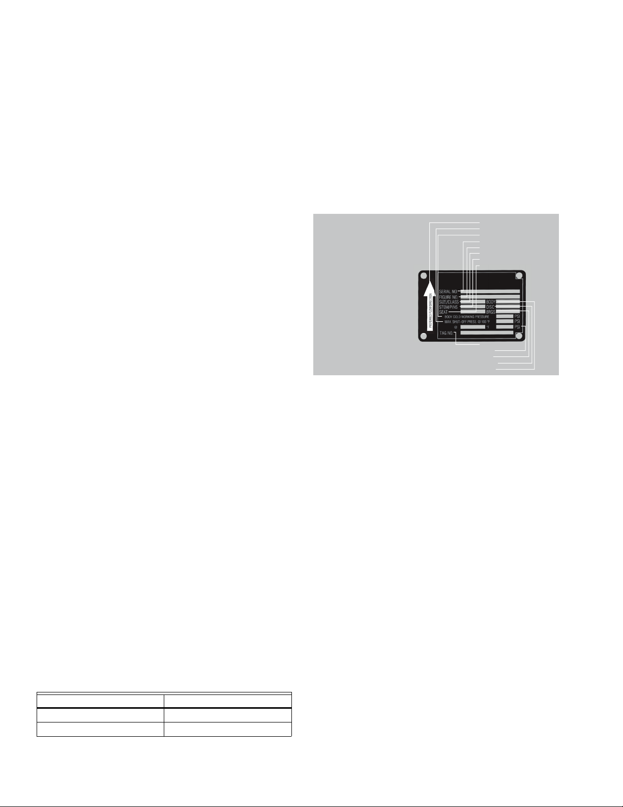
VANNES PAPILLON HAUTE PERFORMANCE VH2 VH3, VH4, VH5, VH6, VH7, VH8 ANSI DE CLASSE 150
INSTALLATION
Conception de la vanne
• La vanne papillon haute performance de série VH
comprend une tige contre-coudée (ou double
excentrique) pour minimiser l’abrasion du siège et
réduire le couple. Cette conception contre-coudée
permet au disque de se soulever et de « pivoter » en
s’éloignant du siège lors de l’ouverture.
• La vanne de série VH tourne toujours en sens horaire
pour se fermer (vue du dessus) et dans le sens
antihoraire pour s’ouvrir.
• Le corps de vanne dispose d’une butée de surcourse qui
empêche le disque de trop pivoter dans le mauvais
quadrant. Cette butée ne doit pas remplacer la butée de
fin de course. Si le disque se rend à la butée de
surcourse, cela signifie qu’il a pivoté plus loin que le
siège.
• La vanne de la série VH doit être installée avec le siège
en amont (SUS). Notez la flèche sur l’étiquette en métal
fixée au corps de la vanne.
Mesures de sécurité
• Veillez à ce que le circuit soit hors pression et vidé.
• N’oubliez pas le liquide dans la conduite. Prenez des
dispositions adéquates pour vous protéger des liquides
toxiques ou inflammables.
• N’installez jamais la vanne sans qu’un actionneur
(manuel ou automatique) ne soit déjà attaché à la tige
de la vanne.
• Ne retirez jamais l’actionneur de la vanne lorsque celleci est dans la conduite sous pression.
• Assurez-vous que le disque est en position
complètement fermée avant d’installer la vanne.
• Faites attention lors de la manipulation de la vanne.
Compatibilité avec la bride
La vanne de série VH est conçue pour s’adapter aux brides
de 2 à 24 po ANSI classe 150.
Compatibilité avec les joints d’étanchéité
La vanne de série VH est conçue pour permettre
l’utilisation de joints d’étanchéité en fibre standard (par
exemple, un matériau sans amiante, en graphite flexible,
en amiante ou d’une matière équivalente) de 1/16 po ou
moins et répondant aux exigences dimensionnelles de la
norme ANSI B16.21-1978. Il n’est pas recommandé
d’utiliser des joints en élastomère épais. Des joints
métalliques enroulés (Flexitallic) peuvent également être
utilisés.
Identification du produit
• Chaque vanne de la série VH est dotée d’une étiquette
d’identification métallique fixée au corps de la vanne.
L’information comprend le numéro de la figure, le
diamètre et la classe de pression, les matériaux de
fabrication, les pressions et les températures de
fonctionnement.
• Chaque vanne de série VH fait l’objet de tests
hydrostatiques avant d’être livrée. L’étiquette en métal
comprend également un numéro de série; ce numéro,
unique pour chaque vanne, est enregistré par le service
de contrôle de la qualité de Honeywell et est
accompagné des résultats des tests et des données de
certification du matériau aux fins de traçabilité
individuelle et de vérification de chaque vanne produite.
SENS D’ÉCOULEMENT PRÉFÉRÉ
PRESS. DE FERMETURE MAX. à 100 °F
PRESSION DE SERVICE, CORPS FROID
Nº DE SÉRIE
Nº DE FIGURE
DIAM./CLASSE
TIGE/BROCHES
SIÈGE
L’étiquette de la vanne
de la série VH indique
le sens de débit
approprié.
Nº D’ÉTIQUETTE
lb/po²
BRGS
DISQUE
CORPS
Fig. 10. Identification de la vanne.
Directives de déballage et d’entreposage
1. Comparez le bordereau d’expédition à la vanne reçue
pour confirmer l’exactitude des quantités, des
diamètres et des matériaux.
2. Assurez-vous que la vanne et l’actionneur n’ont pas
été endommagés pendant le transport.
3. Si la vanne doit être entreposée avant d’être installée,
vous devez la protéger des conditions
environnementales difficiles.
4. Entreposez la vanne avec le disque en position
fermée pour protéger le bord d’étanchéité et le siège.
5. Gardez la vanne dans un endroit propre et loin de la
saleté, des débris et des matières corrosives.
6. Conservez la vanne dans un endroit sec, protecteurs
de bride posés.
7. Gardez la vanne dans un endroit frais et si possible, à
l’abri du soleil.
8. Si la vanne papillon n’est pas utilisée, actionnez-la
(ouverture et fermeture complètes) au moins une fois
par mois.
Compatibilité des séries de tuyau
La vanne de série VH est conçue pour permettre au bord de
disque de pivoter en position ouverte sans interférence
avec la paroi intérieure de la conduite pour les séries de
tuyau suivantes :
Tableau 10. Compatibilité des tuyaux.
Diam. Série du tuyau
2 à 12 po 80
14 à 24 po 40
31-00191EF—02 18
Entreposage des ensembles de vanne papillon
• Les ensembles doivent être entreposés à l’intérieur et
protégés des intempéries.
• Des dispositions doivent être prises pour protéger les
matériaux reçus sur le chantier et dont le délai
d’installation est long contre les dommages de la
construction.
• Les faces de la vanne doivent être protégées contre
l’abrasion, les égratignures et les rayures puisque les
faces seraient ainsi endommagées et pourraient causer
des fuites dans la région de la bride.
• On ne peut pas entreposer des actionneurs électriques
dans des endroits mouillés, humides ou corrosifs.
• N’entreposez pas de matériaux de construction sur les
ensembles.
Page 47
VANNES PAPILLON HAUTE PERFORMANCE VH2 VH3, VH4, VH5, VH6, VH7, VH8 ANSI DE CLASSE 150
AVERTISSEMENT
AVERTISSEMENT
MISE EN GARDE
Pratiques d’installation
• Les vannes papillon de série VH sont conçues pour être
installées entre des brides à collerette soudées à face
plate ou surélevée ANSI 125/150.
• La vanne doit être installée à un minimum de 6
diamètres de tuyau de coudes, de crépines, de pompes,
etc., en amont ou en aval.
• Pour l’eau refroidie, l’eau de condensateur ou l’eau
chaude, la vanne doit être installée avec la tige en
position verticale, l’actionneur étant monté au-dessus
de la vanne.
• Lorsqu’il y a possibilité de sédimentation dans le débit
de liquide, posez la vanne avec la tige en position
horizontale. Le bas du disque doit fermer DEPUIS le
côté en aval plutôt que du côté en amont.
• Des joints de bride doivent être utilisés sur les vannes
des séries VH et BF.
• Assurez-vous que les faces de la bride sont propres et
exemptes de rouille, de calcaire et de débris pour ne pas
endommager le joint de bride.
• Suivez la séquence de boulonnage recommandée à la
Fig. 12.
Installation avec des brides soudées
• Posez les brides des deux côtés du corps de vanne, puis
posez les boulons pour aligner correctement le corps de
vanne sur les deux brides.
• Assurez-vous que les diamètres intérieurs de la vanne et
des brides sont alignés.
• Prenez l’ensemble corps de vanne et bride, puis alignezle sur les extrémités des tuyaux.
• Soudez par points en plusieurs endroits les brides sur
les tuyaux. Ne soudez PAS par joints à ce stade!
• Retirez les boulons d’oreilles, puis séparez avec soin le
corps de vanne des brides.
• Effectuez la soudure par joints du raccordement entre
chaque bride et son tuyau.
• Laissez complètement refroidir les composants de
tuyauterie avant de réinsérer le corps de vanne.
Le soudage par joints alors que le corps de vanne
est installé entre les brides peut endommager les
sièges de vanne en raison de la transmission de
chaleur de la bride au corps de vanne.
Procédure d’avant installation
1. Retirez les couvercles de protection des faces de
vanne.
2. Vérifiez la vanne pour vous assurer que la voie d’eau
est exempte de poussière ou de corps étrangers.
Assurez-vous que la conduite adjacente est exempte
de tout corps étranger tels que la rouille, le calcaire
ou le laitier qui risquent d’endommager le siège et les
surfaces d’étanchéité du disque.
3. Vous devez poser les actionneurs sur la vanne avant
l’installation afin de faciliter l’alignement du disque
dans le siège de vanne.
4. La vanne doit être en position fermée. Assurez-vous
que les positions ouvertes et fermées de l’actionneur
correspondent au sens de rotation d’ouverture
antihoraire de la vanne.
5. Ouvrez, puis fermez complètement la vanne en
vérifiant la fin de course de l’actionneur et
l’alignement du disque.
6. Vérifiez l’étiquette d’identification de la vanne pour
vous assurer que la classe, les matériaux et la
pression de fonctionnement de la vanne sont
conformes à l’usage prévu.
Des blessures corporelles ou des dommages
matériels pourraient survenir si la vanne est
installée lorsque les conditions de service
pourraient dépasser les spécifications de la
vanne.
7. Vérifiez les boulons ou goujons de la bride pour
confirmer leur taille, leur filetage et leur longueur.
N’OUBLIEZ PAS : Installez la vanne avec le disque en
position complètement fermée en utilisant des joints
d’étanchéité appropriés sur les DEUX faces de bride.
Procédure d’installation de vanne
1. La vanne papillon haute performance de série VH
peut être posée dans la conduite avec la tige en
positions verticale, horizontale ou autre (au-dessus
de l’axe du tuyau, Fig. 11). Toutefois, selon notre
expérience, dans des liquides comprenant des
concentrations de particules solides ou abrasives ou
assujettis à une solidification croissante, la
performance et la durée utile de la vanne seront
accrues en posant la vanne avec la tige en position
horizontale.
REMARQUE : Peu importe le type d’actionneur, il doit être
monté au moins dans l’axe de la conduite.
2. Toutes les vannes de la série VH sont directionnelles
et doivent être montées dans la conduite avec la
bague de retenue du siège en amont (sus) pour
assurer une protection maximale du siège.
Pour les vannes de la série VH :
a. En prenant note de la flèche du sens
d’écoulement sur l’étiquette, placez la vanne
entre les brides, en vous assurant que la flèche
sur l’étiquette pointe dans le sens d’écoulement.
b. Installez lâchement les boulons inférieurs de
bride en laissant de l’espace pour les joints de
bride.
c. Après avoir inséré les joints de bride, installez les
autres boulons.
3. À l’aide de la séquence indiquée sur la Fig. 12, serrez
les boulons de bride uniformément pour assurer une
compression uniforme du joint d’étanchéité.
La vanne de gamme VH doit être centrée entre les
brides et les joints d’étanchéité pour ne pas
endommager le bord de disque et la tige à la suite
d’un choc entre le disque et la bride, le joint ou le
tuyau.
4. Les raccordements électriques doivent être effectués
conformément aux directives du fabricant de
l’actionneur.
5. La vanne est maintenant prête à fonctionner.
19 31-00191EF—02
Page 48

VANNES PAPILLON HAUTE PERFORMANCE VH2 VH3, VH4, VH5, VH6, VH7, VH8 ANSI DE CLASSE 150
90° 90°
31
24
1
4
3
2
5
6
7
8
9
10
11
12
13
14
15
16
1
4
3
2
5
6
7
8
9
10
11
12
1
4
3
2
5
6
7
8
Fig. 11.
Tableau 11. Recommandations relatives au boulonnage des brides.
Diamètre
de la
vanne
(pouces) Filetage
2 5/8-11 4 2,5 4 2,5 4 1,63 4 1,63
2,5 5/8-11 4 2,75 4 2,75 4 1,85 4 1,85
3 5/8-11 4 3,25 4 2,5 4 2,25 4 1,63
45/8-118 3 82,7582,1281,88
53/4-1083838282
6 3/4-10 8 3,5 8 3 8 2,5 8 1,88
8 3/4-10 8 3,75 8 3,25 8 2,7 8 2,13
10 7/8-9 12 4,25 12 3,5 12 3 12 2,25
12 7/8-9 12 4,75 12 3,5 12 3,45 12 2,35
14 1-8 12 5 12 4 12 3,75 12 2,7
16 1-8 16 5,5 16 4,25 16 4,12 16 2,75
181-1/8-8165,75164,75164,38163,25
20
241-1/4-8207,25205,75205,63204,25
1-1/8-8166,75164,75165,12163,25
1-1/8-8 4 5,5 4 4,75 4 4,12 4 3,25
QTÉ
C
Fig. 12. Séquence de boulonnage.
Goujons et écrous Boulons mécaniques
Longueur
(pouces)
D
QTÉ
Longueur
(pouces)
F
QTÉ
Longueur
(pouces)
G
QTÉ
Longueur
(pouces)
31-00191EF—02 20
Page 49

VANNES PAPILLON HAUTE PERFORMANCE VH2 VH3, VH4, VH5, VH6, VH7, VH8 ANSI DE CLASSE 150
CORPS À OREILLES
BOULONS MÉCANIQUES À
TÊTE HEXAGONALE
CORPS À OREILLES
GOUJONS ET ÉCROUS
Fig. 13. Boulonnage.
Fig. 14. Brides.
Les recommandations de boulonnage et de couple sont fournies sans garantie et s’appliquent uniquement aux brides
soudées ou à emmancher en acier.
L’utilisation de rondelles de blocage ou de lubrification lors du boulonnage aura une incidence sur les valeurs de couple
mentionnées.
La longueur des boulons mécaniques est fondée sur :
1. Une épaisseur de joint d’étanchéité de 0,06 po.
2. Épaisseur minimale de brides soudées conforme aux normes ANSI B16.5 et B16.47 série A.
* Ne pas respecter la longueur de boulonnage spécifiée pourrait entraîner une installation inadéquate.
Tableau 12. Dimensions des brides.
BRIDES FORAGE BOULONNAGE
Diamètre C du
Diamètre
nominal du
tuyau (po)
Diamètre de
bride A (po)
Épaisseur de
bride B (po)
cercle de
boulonnage
(po)
Diamètre D des
trous de
boulons (po)
Nombre de
boulons
Diamètre des
boulons
2 6 0,75 4,75 0,75 4 0,625
2,5 7 0,875 5,5 0,75 4 0,625
3 7,5 0,9375 6 0,75 4 0,625
4 9 0,9375 7,5 0,75 8 0,625
5 10 0,9375 8,5 0,875 8 0,75
6 11 1 9,5 0,875 8 0,75
8 13,5 1,125 11,75 0,875 8 0,75
10 16 1,1875 14,25 1 12 0,875
12 19 1,25 17 1 12 0,875
14 21 1,375 18,75 1,125 12 1
16 23,5 1,4375 21,25 1,125 16 1
18 25 1,625 22,75 1,25 16 1,125
20 27,5 1,6875 25 1,25 20 1,125
24 32 1,875 29,5 1,375 20 1,25
21 31-00191EF—02
Page 50

VANNES PAPILLON HAUTE PERFORMANCE VH2 VH3, VH4, VH5, VH6, VH7, VH8 ANSI DE CLASSE 150
MBS8U3N2/U and MBS8U3S2/U
Noir (1) Neutre
Rouge (2) + Sous
tension
Transformateur 24 V c.a.
Tension
secteur
2 3
18
A
a
Fonction
100%
Max.
a
Remarques :
Marche/arrêt
Interrupteurs auxiliaires
Répond aux exigences cULus sans raccordement
de mise à la terre.
A
Les actionneurs avec les câbles de l’appareil sont
numérotés.
2
Les actionneurs peuvent être raccordés en parallèle.
La consommation électrique et l’impédance d’entrée
doivent être respectées.
3
Les actionneurs peuvent également être alimentés
à 24 V c.c.
18
Les actionneurs dotés de câbles pour plénum n’ont
pas de numéros sur les fils; utilisez le code-couleurs.
2 3
Noir (1) Neutre
Rouge
(2)
+ Sous
tension
Blanc
(3)
+ Entrée
a
18
Fonction
100%
Max.
a
2 3
18
a
b
Fonction
100%
Max.
a
b
Remarques :
Point flottant
Répond aux exigences cULus sans raccordement
de mise à la terre.
2
Les actionneurs peuvent être raccordés en parallèle.
La consommation électrique et l’impédance d’entrée
doivent être respectées.
3
Les actionneurs peuvent également être alimentés
à 24 V c.c.
18
Les actionneurs dotés de câbles pour plénum n’ont
pas de numéros sur les fils; utilisez le code-couleurs.
Tension
secteur
Transformateur 24 V c.a.
Marche/arrêt
Tension
secteur
Transformateur 24 V c.a.
Noir (1)
Rouge
(2)
Blanc
(3)
Neutre
+ Sous
tension
+ Entrée
Remarques :
7
Noir (1) Neutre
Rouge
(2)
+
Sous tension
Rose
(4)
Y
2
Entrée
Blanc
(3)
Y
1
Entrée,
2 à 10 V c.c.
Orange
(5)
Sortie U, 2 à 1
(–)
(+)
Ω
500 Ω
1/4
Watt
3 18
Signal de commande
18
Fonctions
0%
50%
100%
Mode de commande
acc. à Y
Min.*
Médian*
Max.*
Normal**
* Sélectionnable par défaut 0-100 %. Voir la fiche
technique de configuration
** Personnalisable. Voir la fiche technique de configuration
abc
500 Ω
Ω
Neutre
+
Sous tension
Y
2
Entrée
Y
1
Entrée
,
2 à 10 V c.c.
(–)
(+)
Transformateur de 24 V c.a.
(c.a. seulement)
7
B
C
A
1/4 Watt
V c.c./4 à 20 mA Positions Min., Médian et Max. de commande d’annulation
Répond aux exigences cULus sans raccordement
de mise à la terre.
3
Les actionneurs peuvent également être
alimentés à 24 V c.c.
7
Une résistance de 500 Ω transforme le signal de
commande de 4 à 20 mA en tension de 2 à 10 V c.c.
18
Les actionneurs dotés de câbles pour plénum
n’ont pas de numéros sur les fils; utilisez le
code-couleurs.
Transformateur 24 V c.a.
Tension
secteur
4 à 20 mA ou 2 à 10 V c.c.
Tension
secteur
Signal de commande
2 à 10 V c.c. ou 4 à 20 mA
Noir (1)
Rouge
(2)
Rose (4)
Blanc (3)
Orange
(5)
INSTALLATION ÉLECTRIQUE
Fig. 15. Câblage pour les actionneurs MBS8.
Fig. 16. Câblage pour actionneurs MBP6...R.
Fig. 17. Câblage pour actionneurs MBS7...1 et MBS7...R.
31-00191EF—02 22
Page 51

VANNES PAPILLON HAUTE PERFORMANCE VH2 VH3, VH4, VH5, VH6, VH7, VH8 ANSI DE CLASSE 150
18
Noir (1) Neutre
Rouge
(2)
Sous tension
Blanc
(3)
Y Entrée
Orange
(5)
Sortie U
2 à 10 V c.c.
Signal de rétroaction
de 2 à 10 V c.c.
(+)
(–)
3
Fonction
100%
Max.
a
(–)
(+)
CCW
CW
AB
18
CCW
CW
AB
Contacteur de sens de rotation
A
B
2
9
8
10
12
18
18
Remarques :
Marche/arrêt
Point flottant
Répond aux exigences cULus sans raccordement
de mise à la terre.
2
Les actionneurs peuvent être raccordés en parallèle.
La consommation électrique et l’impédance d’entrée
doivent être respectées.
3
Les actionneurs peuvent également être alimentés
à 24 V c.c.
8
Le signal de commande peut être pulsé par le fil
sous tension (source) ou le fil neutre (collecteur)
d’un circuit 24 V c.a.
9
Les fermetures de contact A et B peuvent également
être à triac. Les contacteurs A et B doivent être fermés
pour la source à triac et ouverts pour le collecteur à triac.
10
Pour un collecteur à triac, le fil neutre de l’actionneur
doit être raccordé au fil sous tension du régulateur. La
rétroaction de position ne peut pas être utilisée avec un
régulateur à collecteur à triac. La référence neutre interne
de l’actionneur n’est pas compatible.
Diode IN4004 ou IN4007. (IN4007 fournie)
18
Les actionneurs dotés de câbles pour plénum n’ont
pas de numéros sur les fils; utilisez le code-couleurs.
FC FO
A – AB = 0% A – AB = 100%
POP
POP
CW
CCW
CWCCW
24 V c.a./c.c.
FC FO
A – AB = 0% A – AB = 100%
3
a
(Y1)
4
b
(Y2)
CWCCW
0.1
0.5
Y2
Y1
0.9
POP
0.1
0.5
0.9
POP
CWCCW
Y2
Y1
–– ––
24V c.a./c.c.
Marche/arrêt
Point flottant
12
Signal de rétroaction
de 2 à 10 V c.c.
Transformateur 24 V c.a. Transformateur 24 V c.a.
Tension
secteur
Tension
secteur
Noir (1) Neutre
Rouge
(2)
Sous tension
Blanc
(3)
Y
1
Entrée
Orange
(5)
Sortie U
2 à 10 V c.c.
Fig. 18. Câblage pour actionneurs MBE6...R.
23 31-00191EF—02
Page 52

VANNES PAPILLON HAUTE PERFORMANCE VH2 VH3, VH4, VH5, VH6, VH7, VH8 ANSI DE CLASSE 150
Point flottant
Contacteurs de fin de course
Remarques :
0 à 90°;
85° par
défaut
41!
1
Prévoyez des mécanismes de coupure et de protection
les surcharges, au besoin.
46
Les actionneurs peuvent être commandés en parallèle.
L’appel de courant et l’impédance d’entrée doivent être respectés
4
Deux interrupteurs auxiliaires (2 x SPDT), pour l’indication
de position de fin de course, la commande de verrouillage,
la mise en fonction du ventilateur, etc.
Les modèles à alimentation électrique tous courants
peuvent être alimentés de 24 V c.a. à 240 V c.a. ou de
24 V c.c. à 125 V c.c.
Marche/arrêt
N
L
Y
1
Y2
1UP46
!
N
L
Y
1
Y2
1UP46
!
Neutre
+ Sous tension
N
L
Y
1
Y2
Neutre
+ Sous tension
Entrée sens
antihoraire
(ouverture)
Entrée sens horaire
(fermeture)
24 à 240 V. c. a.
ou
24 à 125 V. c. c.
1
UP
46
1
!
Marche/arrêt
!
Durant l’installation, la mise à l’essai, l’entretien et le
dépannage de ce produit, il peut être nécessaire de travailler
avec les composants électriques sous tension. Faites
exécuter ces tâches par un électricien qualifié ou par une
personne correctement formée dans la manipulation de
composants électriques sous tension. Le non-respect des
mesures de sécurité pour le travail avec l’électricité pourrait
entraîner des blessures graves, voire mortelles.
Répond aux exigences cULus sans raccordement
de mise à la terre.
24 à 240 V. c. a.
ou
24 à 125 V. c. c.
Entrée sens
antihoraire
(ouverture)
Entrée sens horaire
(fermeture)
Neutre
+ Sous tension
Entrée sens
antihoraire
(ouverture)
Entrée sens horaire
(fermeture)
24 à 240 V. c. a.
ou
24 à 125 V. c. c.
HAUT
HAUTHAUT
HAUT
Transformateur 24 V c.a.
Tension
secteur
Signal de commande
V. c c./mA
3 18
Noir (1) Neutre
Rouge
+ Sous tension
(2)
500 Ω
Ω
1/4 Watt
(–)
(+)
7
Blanc
(3)
Orange
(5)
Y
Entrée
1
2 à 10 V c.c
Sortie U
2 à 10 V c.c.
,
Transformateur 24 V c.a.
Tension
secteur
Ω
Signal de commande
Min.*
Médian*
Max.*
Normal**
* Sélectionnable par défaut 0-100 %. Voir la fiche
technique de configuration.
** Personnalisable. Voir la fiche technique de configuration.
(–)
V. c c./mA
(+)
7
Fonctions
0%
50%
100%
Mode de commande
acc. à Y
500 Ω
1/4 Watt
abc
A
B
C
18
Noir (1) Neutre
Rouge
+ Sous tension
(2)
Blanc
Entrée
Y
1
(3)
2 à 10 V c.c
Sortie U
Orange
2 à 10 V c.c.
(5)
Remarques :
,
10
18
Répond aux exigences cULus sans raccordement de
mise à la terre.
Les actionneurs peuvent également être alimentés
3
à 24 V c.c.
Une résistance de 500 Ω transforme le signal de
7
commande de 4 à 20 mA en tension de 2 à 10 V c.c.
Pour un collecteur à triac, le fil neutre de l’actionneur
doit être raccordé au fil sous tension du régulateur.
La rétroaction de position ne peut pas être utilisée
avec un régulateur à collecteur à triac. La référence
neutre interne de l’actionneur n’est pas compatible.
Les actionneurs dotés de câbles pour plénum
n’ont pas de numéros sur les fils; utilisez le
code-couleurs.
V c.c./4 à 20 mA Positions Min., Médian et Max. de commande d’annulation
FC FO
A – AB = 0% A – AB = 100%
0.1
Y1
Y2
0.5
POP
0.9
CWCCW
0.1
Y1
Y2
0.5
POP
0.9
CWCCW
Modulation
24 V c.a./c.c.
Fig. 19. Câblage pour actionneurs MBE7...R.
31-00191EF—02 24
Fig. 20. Câblage pour actionneurs MBP, E6...6.
Page 53

VANNES PAPILLON HAUTE PERFORMANCE VH2 VH3, VH4, VH5, VH6, VH7, VH8 ANSI DE CLASSE 150
S2 S3
S5 S6
S4
S5 S6
S4
0 à 90°;
85° par
défaut
Contacteurs de fin de course
Optional: end switch adjustment
A
o
p
e
n
2
1
S1 S2 S3 S4 S5 S6
4
Remarques :
41!
24 à 240 V. c. a.
ou
24 à 125 V. c. c.
V c.c./4 à 20 mA
UP
N
L
Y
1
Y2
N
-
+
Y
3
U5
HAUT
5
1
Neutre -
Sortie 24 V c.c.
0 - 10 V. c. c.**
Y
3
U5/MP 0 - 10 VD
46
HAUT
Répond aux exigences cULus sans raccordement
de mise à la terre.
Prévoyez des mécanismes de coupure et de protection
1
contre les surcharges, au besoin.
Raccordez uniquement le fil neutre à la partie négative
5
(1) des circuits de commande.
Deux interrupteurs auxiliaires (2 x SPDT), pour
4
l’indication de position de fin de course, la commande
de verrouillage, la mise en fonction du ventilateur, etc.
Les actionneurs peuvent être commandés en parallèle.
46
L’appel de courant et l’impédance d’entrée doivent être
respectés.
Les modèles à alimentation électrique tous courants
peuvent être alimentés de 24 V c.a. à 240 V c.a. ou de
24 V c.c. à 125 V c.c.
Durant l’installation, la mise à l’essai, l’entretien et le
!
dépannage de ce produit, il peut être nécessaire de
travailler avec les composants électriques sous tension.
Faites exécuter ces tâches par un électricien qualifié ou
par une personne correctement formée dans la
manipulation de composants électriques sous tension.
Le non-respect des mesures de sécurité pour le travail
avec l’électricité pourrait entraîner des blessures graves,
voire mortelles.
Fig. 21. Câblage pour actionneurs MBP, E7...6.
B
S1
10°
3
S2S3
S5S6S4S5S6
S4
o
p
e
n
Boutons-poussoirs et affichage
5
Power
Status
6
Couper l’alimentation.
Dégagement de l’engrenage
1
Ouvrez le couvercle de contournement manuel et y insérer
la manivelle à main. Le contournement manuel est possible.
Contournement manuel
2
Tournez la manivelle jusqu’à ce que indique la position
de commutation souhaitée, puis retirez la manivelle.
Interrupteur auxiliaire
3
Ouvrez le couvercle de réglage de l’interrupteur auxiliaire
et placez correctement la manivelle à main dans l’actionneur.
Tournez la manivelle jusqu’à ce que la flèche pointe vers
B
la ligne verticale.
Bornes
4
Branchez le vérificateur de continuité S4 + S5 ou S4 + S6.
Si l’interrupteur auxiliaire doit commuter en sens inverse,
tournez la manivelle de 180°
Affichage DEL vert
5
6 Affichage DEL jaune fermé : Aucune alimentation ni
anomalie, Marche : En fonction Appuyez sur le bouton :
Déclenche l’essai suivi du mode standard
Affichage DEL jaune
6
Désactivée : Mode standard, Marche : Mode d’essai actif.
A
Fig. 22. Réglage de l’interrupteur, modèles MBP, E.... 6.
25 31-00191EF—02
Page 54

VANNES PAPILLON HAUTE PERFORMANCE VH2 VH3, VH4, VH5, VH6, VH7, VH8 ANSI DE CLASSE 150
Transformateur de 24 V c.a/V c.c.
Marche/arrêt
33
Chaque actionneur doit être alimenté par un seul
transformateur de commande isolé.
MBP...9, B
REMARQUES SUR L’INSTALLATION
• Respectez les restrictions de câblage de
classe 1 et de classe 2.
• Calibrage du transformateur = appel de courant de
l’actionneur MBP x 1,25 (marge de sécurité)
Transformateur de 24 V c.a
G Terre
1 Neutre
3 Ouvert
4 Fermé
5
6
7
HTR
A
B
C
D
E
F
LS3
A-C
(Indication d’ouverture)
LS4
D-F
(Indication de fermeture)
Valeur nominale des contacts :
5 A, 250 RMS max.
MBP...9, B
G Terre
1 Neutre
3 Ouvert
4 Fermé
5
6
7
HTR
A
B
C
D
E
F
LS3
A-C
(Indication d’ouverture)
LS4
D-F
(Indication de fermeture)
Valeur nominale des contacts :
5 A, 250 RMS max.
MBP...9, B
K1
Ouvrir
Fermer
K1-B
K1-A
Actionneur A
Actionneur B
G
G
REMARQUES SUR L’INSTALLATION
• Les relais d’isolation doivent être raccordés en parallèle de plusieurs
actionneurs utilisant une entrée de signal de commande commune.
• « H » (L2) ne peut pas être raccordé simultanément à la borne 3 et la borne 4.
• Requis : La borne 7 doit être câblée sur place pour activer le circuit de chauffage.
Tension
secteur
Régulation proportionnelle, plusieurs câbles,
MBP...9, B
A
B
C
D
E
F
LS3
A-C
(Indication d’ouverture)
LS4
D-F
(Indication de fermeture)
Valeur nominale des contacts :
5 A, 250 RMS max.
SY2…5-24MFT
5
┴
2
9
8
0
3
2
┴
/
-
T
5
┴
2
9
8
0
3
2
┴
/
-
T
33
35
36
35
36
33
Chaque actionneur doit être alimenté
par un seul transformateur de commande
isolé.
MBP...9, B
REMARQUES SUR L’INSTALLATION
• Respectez les restrictions de câblage de classe 1 et de classe 2.
• Calibrage du transformateur = appel de courant de l’actionneur
MBP x 1,25 (marge de sécurité)
Actionneur A
Actionneur B
Prise d’entretien
de l’outil PC
Signal de commande (+)
Signal de commande (1)
Signal de rétroaction (+)
Signal de rétroaction (-)
Rétroaction
Signal de commande
Signal de commande (+)
Signal de commande (1)
Signal de rétroaction (+)
Signal de rétroaction (-)
Prise d’entretien
de l’outil PC
Adresse
Adaptation
Adresse
Adaptation
Pour usage interne seulement
Pour usage interne seulement
Pour usage interne seulement
Pour usage interne seulement
Pour usage interne seulement
Pour usage interne seulement
Pour usage interne seulement
Pour usage interne seulement
Neutre, bloc d’alimentation
Sous tension, bloc d’alimentation
24 V. c.c. / V. c.a.
33
Pour usage interne seulement
Pour usage interne seulement
Pour usage interne seulement
Pour usage interne seulement
Pour usage interne seulement
Pour usage interne seulement
Pour usage interne seulement
Pour usage interne seulement
Neutre, bloc d’alimentation
Sous tension, bloc d’alimentation
24 V. c.c. / V. c.a.
Rétroaction
Transformateur de 24 V c.a/V c.c.
33
Tension
secteur
Ouvrir
Fermer
G
G Terre
1 Neutre
3 Ouvert
4 Fermé
Se brancher au nº 1 pour
5
une indication d’ouverture
complète
Se brancher au nº 1 pour
6
une indication de fermeture
complète
7
HTR
A
LS3
B
(Indication d’ouverture)
A-C
C
D
LS4
E
(Indication de fermeture)
D-F
F
Valeur nominale des contacts :
5 A, 250 RMS max.
SY2…5-24
Fig. 23. Câblage pour actionneurs MBP6... 9, B.
31-00191EF—02 26
A
B
1
Y
1
Non utilisé -
Non utilisé -
Non utilisé -
Non utilisé -
┴
U
C1
C2
PE
Y
1
┴
U
C1
C2
PE
SYx-24MF
Y1 Y2
Y1 Y2
SYx-24MF
G
Fig. 24. Câblage pour actionneurs MBP7... 9, B.
G
~/+
1
A
B
1
~/+
1
Page 55

VANNES PAPILLON HAUTE PERFORMANCE VH2 VH3, VH4, VH5, VH6, VH7, VH8 ANSI DE CLASSE 150
120 V c.a./V c.c.
Marche/arrêt
G
1
3
4
5
6
7
120V
G
N L1
H L2
HTR
A
B
C
D
E
F
LS3
A-C
LS4
D-F
SY2…12-120V or 230V
MBP...C, D, E
REMARQUES SUR
L’INSTALLATION
• Respectez les restrictions de câblage de classe 1 et de classe 2.
• Calibrage du transformateur = appel de courant de l’actionneur MBP x 1,25 (marge de sécurité)
G
1
3
4
5
6
7
HTR
A
B
C
D
E
F
LS3
A-C
LS4
D-F
.
G
1
3
4
5
6
7
HTR
A
B
C
D
E
F
LS3
A-C
LS4
D-F
MBP, C, D, E
MBP...C, D, E
Open
Close
K1-B
K1-A
Actionneur A
Actionneur B
120 V c.a.
N L1
H L2
G
G
K1
REMARQUES SUR
L’INSTALLATION
• Les relais d’isolation doivent être raccordés en
parallèle de plusieurs actionneurs utilisant une
entrée de signal de commande commune.
• « H » (L2) ne peut pas être raccordé simultanément
à la borne 3 et la borne 4.
• Requis : La borne 7 doit être câblée sur place pour
activer le circuit de chauffage.
Terre
Neutre
Ouvert
Fermé
(Indication d’ouverture)
(Indication de fermeture)
Valeur nominale des contacts :
5 A, 250 RMS max.
Se brancher au nº 1 pour
une indication d’ouverture
complète
Se brancher au nº 1 pour
une indication de fermeture
complète
Terre
Neutre
Ouvert
Fermé
Se brancher au nº 1 pour
une indication d’ouverture
complète
Se brancher au nº 1 pour
une indication de fermeture
complète
(Indication d’ouverture)
(Indication de fermeture)
Valeur nominale des contacts :
5 A, 250 RMS max.
Terre
Neutre
Ouvert
Fermé
(Indication d’ouverture)
(Indication de fermeture)
Valeur nominale des contacts :
5 A, 250 RMS max.
Ouvrir
Fermer
Fig. 25. Câblage pour actionneurs MBP6... D, E, F, G.
27 31-00191EF—02
Page 56

VANNES PAPILLON HAUTE PERFORMANCE VH2 VH3, VH4, VH5, VH6, VH7, VH8 ANSI DE CLASSE 150
┴
5
2
9
8
0
3
2
T
T
L
5
2
9
8
0
3
2
T
T
L
Régulation proportionnelle, plusieurs câbles, 120V
MBP...C, D, E
Neutre, bloc d’alimentation – 120V
Sous tension, bloc d’alimentation – 120V
A
B
1
AdresseAdaptation
Y1
Y2
1
Neutre, bloc d’alimentatio
Sous tension, bloc d’alime
A
B
1
AdresseAdaptation
Y1
Y2
1
Pour usage interne seulement
Pour usage interne seulement
Pour usage interne seulement
Pour usage interne seulement
Pour usage interne seulement
Pour usage interne seulement
Pour usage interne seulement
Pour usage interne seulement
Pour usage interne seulement
Pour usage interne seulement
Pour usage interne seulement
Pour usage interne seulement
Pour usage interne seulement
Pour usage interne seulement
Pour usage interne seulement
Pour usage interne seulement
Signal de commande
A
LS3
B
(Indication d’ouverture)
A-C
C
D
LS4
E
(Indication de fermeture)
D-F
F
Valeur nominale des contacts :
5 A, 250 RMS max.
MBP...C, D, E
Rétroaction
Rétroaction
36
SYx-120MF
SYx-230MF
SYx-120MF
SYx-230MF
N
N
Prise d’entretien
de l’outil PC
Prise d’entretien
de l’outil PC
Non utilisé -
Non utilisé -
Non utilisé -
Non utilisé -
Y
1
U
┴
C1
C2
PE
Actionneur A
Y
1
┴
U
┴
C1
C2
PE
Actionneur B
Signal de commande (+)
Signal de commande (1)
Signal de rétroaction (+)
36
Signal de rétroaction (-)
35
G
Signal de commande (+)
Signal de commande (1)
Signal de rétroaction (+)
Signal de rétroaction (-)
35
G
Chaque actionneur doit être alimenté par
33
un seul transformateur de commande isolé.
REMARQUES SUR L’INSTALLATION
• Respectez les restrictions de câblage de classe 1 et de classe 2.
• Calibrage du transformateur = appel de courant de l’actionneur
MBP x 1,25 (marge de sécurité)
Fig. 26. Câblage pour actionneurs MBP7... D, E, F, G.
Par l'utilisation de la présente documentation Honeywell, vous consentez à ce qu'Honeywell ne possède aucune responsabilité
pour tous dommages résultant de votre utilisation ou modification de ladite documentation. Vous défendrez et indemniserez
Honeywell, ses sociétés affiliées, filiales pour et contre toute responsabilité, frais ou dommages, y compris les honoraires
d'avocats, résultant de quelque manière, ou survenant en connexion avec toute modification à la documentation de votre part.
Honeywell Building Technologies
Aux États-Unis :
Honeywell
® Marque de commerce déposée aux États-Unis
© 2019 Honeywell International Inc.
31-00191EF—02 M.S. Rev. 07-19
Imprimé aux États-Unis
 Loading...