

Page 1
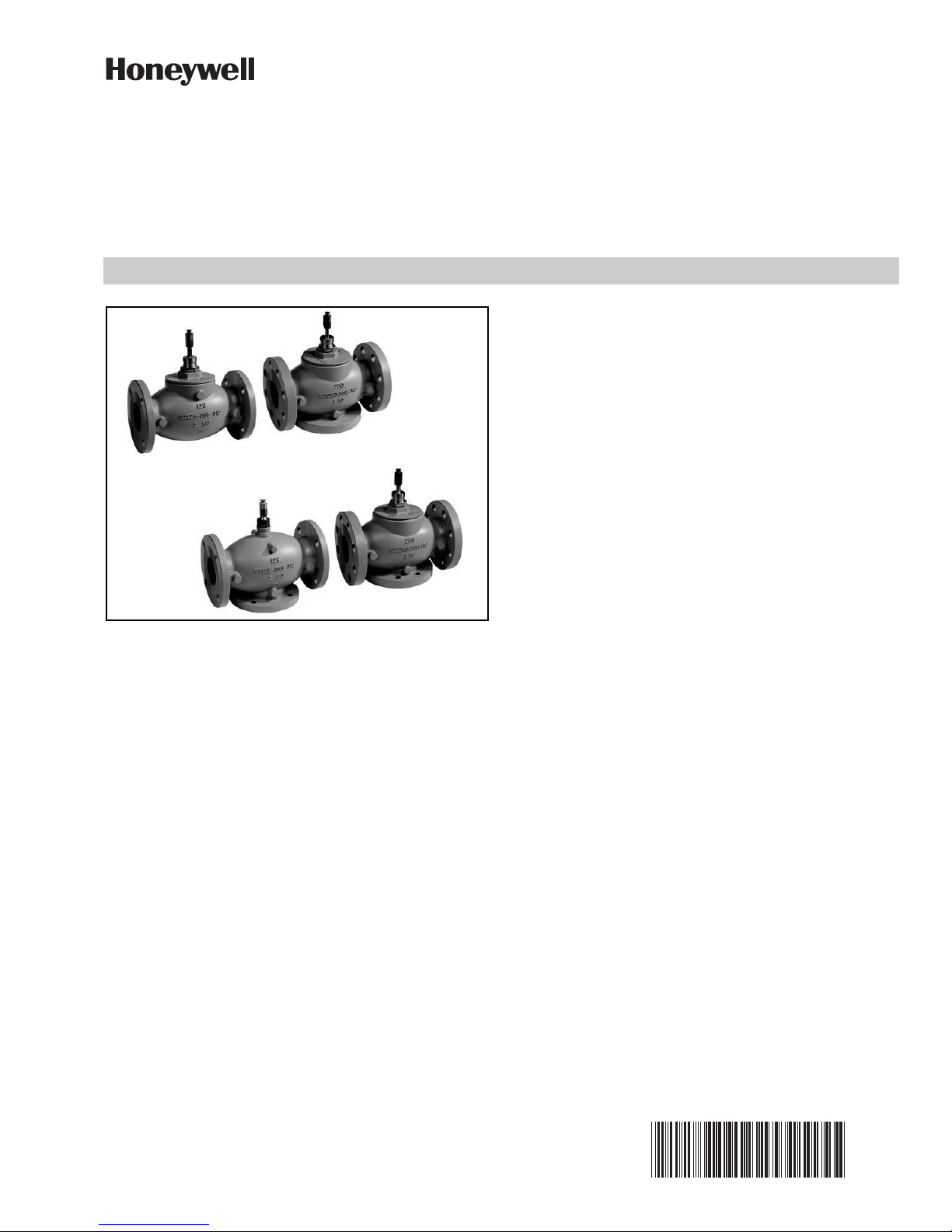
VGF22
VGF21
VGF31
VGF32
VGF Flanged Globe Valves
SPECIFICATIONS
Models: See Tables 2 and 3.
Dimensions: See Fig. 3 and 4.
Action:
Mixing valves: Stem up to close port A-AB.
All others: Stem down to close port A-AB.
Controlled Media:
Water up to 50% glycol solution.
Saturated steam (2-way models) up to 100 psig.
Not suitable for open loop systems such as condenser
water or potable water.
Valve Body Temperature-Pressure Ratings:
Water: ANSI Class 125 and 250. See Table 1.
Steam: 337°F (170°C); 100 psig (689 kPa).
Flow Capacity: See Table 8.
Stroke and Mounting:
2-1/2 and 3 inch (DN65 and DN80): 3/4 in. (20mm)
APPLICATION
VGF Flanged Globe Valves are used for 2-position or
modulating control of steam, hot water, or chilled water in
closed loop HVAC systems. They can be operated by a
large variety of electric and pneumatic actuators. Threeway valves are available in mixing or diverting flow
patterns.
FEATURES
• ANSI Class 125 and Class 250 flanged cast iron
bodies.
• Face-to-face flange dimensions per ANSI/ISA S75.03
standard.
• Sizes from 2-1/2 to 6 inches (DN65 to DN150).
• Metal-to-metal seating for long life span.
• Differential pressure of 175 psi, ANSI Class IV
leakage on pressure-balanced models.
• Steam inlet pressure up to 100 psig (689 kPa).
• Self-adjusting packing.
• Equal percentage and linear flow characteristics to
ensure precise control in a variety of applications.
Related Literature
— 62-0213 VGF Installation Instructions
— 63-1301 VGF Specification Data
— 63-9271 Field Devices Catalog (for compatible
actuators)
stroke, 1-3/8 in. bonnet, 1/4-28 UNF stem thread and
button.
4 to 6 inch (DN100 to DN150): 1-1/2 in. (38mm) stroke,
1-7/8 in. bonnet, 7/16-20 UNF stem thread, and button.
Maximum Temperature Differential
(alternating hot/cold water): 108°F (60°C).
Flow Characteristic:
VGF2__E_: Equal percentage.
VGF2__L_: Linear.
VGF3_EM_ Mixing Valve: Equal percentage port A-AB, Lin-
ear port B-AB.
VGF3_LD_ Diverting Valve: Linear.
Rangeability: 50:1.
Close-Off Pressure (maximum):
VGF21_P pressure-balanced: 175 psi (1207 kPa).
All others: Proportional to actuator force. See Tables 4, 5.
and 6.
Leakage Rate (maximum):
VGF21_P pressure-balanced: 0.01% of Cv (ANSI Class IV).
VGF2__S: 0.05% of Cv (ANSI Class III).
Three-way:
VGF31EM and VGF32EM <.05% of CV A to AB (ANSI
Class III), <.1% of CV B-AB
VGF31LD and VGF32LD <.05% of CV AB to A (ANSI
Class III), <.1% of CV AB-B
PRODUCT DATA
63-2618-01
Page 2

VGF FLANGED GLOBE VALVES
Table 2. VGF2 2-way.
VGF2 Valve, Globe, Flanged, 2-way
1 ANSI 125
2 ANSI 250
EP Equal percent flow, pressure-balanced
a
ES Equal percent flow, standard
LP Linear flow, pressure-balanced
a
LS Linear flow, standard
a
25 2-1/2 in. ports
30 3 in. ports
40 4 in. ports
50 5 in. ports
60 6 in. ports
VGF2 1 EP 30
e.g.: 3 in. flanged, equal percent, pressure balanced, ANSI 125
a
ANSI 125 only
Table 3. VGF3 3-way.
VGF3 Valve, Globe, Flanged, 3-way
1 ANSI 125
2 ANSI 250
EM Equal percentage flow, mixing
LD Linear flow, diverting
25 2-1/2 in. (DN65) ports
30 3 in. (DN80) ports
40 4 in. (DN100) ports
50 5 in. (DN125) ports
60 6 in. (DN150) ports
VGF3 2 EM 40
e.g.: 4 in. (DN100) flanged mixing valve, ANSI
250
Valve Body:
End connections:
Face-to-face flange dimensions per ANSI/ISA 75.03.
Bolt holes conform to ANSI B16.1. VGF3 valves have
standard ANSI flange connections on A and AB
ports. B ports have lugged connections. See Table 7.
VGF3 B-Port Threads
Material: Cast iron, ASTM A126 Class B (GG25).
Trim:
Seat:
Mixing valve: body integrated (cast iron).
All others: Stainless steel.
Plug: Stainless steel, skirt guided.
Stem: Stainless steel.
Packing: Spring loaded PTFE cone rings.
Accessories:
43196000-001 High Temperature Kit. Fits 2 1/2 and
3" VGF valves.
43196000-038 High Temperature Kit. Fits 4 to 6" VGF
valves.
R43176754002 Packing Kit for 2-1/2 in. and 3 in. VGF21
and VGF31 valves.
R43176755004 Packing Kit for 2-1/2 in. and 3 in. VGF22,
VGF32, VGF21EP, and VGF21LP valves.
R43176755005 Packing Kit for all 4 in. to 6 in. VGF valves.
Replacement stem buttons:
2-1/2 to 3 in (DN65-80): 209117
4 to 6 in (DN100-150): 209116
NOTE: Packing kits include copper ring, spring, bearing,
packing, and gasket.
Table 1. Water Temperature and Maximum Pressure.
Temperature
°F (°C)
VGF21, VGF31 VGF22, VGF32
System Pressure
35 to 130 (2-66) 175 psig (1206 kPa) 400 psig (2758 kPa)
Up to 200 (< 93) 165 psig (1138 kPa) 370 psig (2251 kPa)
Up to 250 (< 121) 150 psig (1034 kPa) 340 psig (2344 kPa)
Up to 300 (< 149) 140 psig (965 kPa) 310 psig (2137 kPa)
Up to 337 (<170) 125 psig (862 kPa) 280 psig (1931 kPa)
63-2618—01 2
Page 3
VGF FLANGED GLOBE VALVES
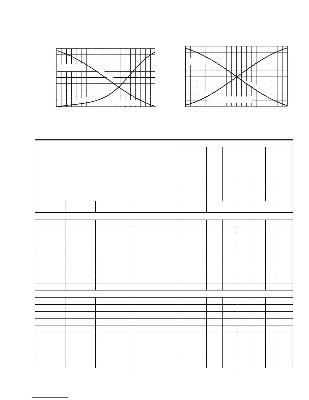
LINEAR FLOW
NORMALLY OPEN
A TO AB FOR 2 WAY LS AND LP MODELS
AB TO A FOR 3 WAY DIVERTING
70% 80% 90%
STEM TRAVEL (% OF STROKE)
60%
M22598A
FLOW
(% OF CV)
100%
90%
80%
70%
B TO AB FOR 3 WAY
MIXING VALVE
60%
50%
40%
30%
20%
10%
0%
EQUAL PERCENTAGE FLOW
NORMALLY OPEN
NORMALLY CLOSED
A TO AB FOR 2 WAY EP AND ES MODELS
A TO AB FOR 3 WAY MIXING
STEM TRAVEL (% OF STROKE)
100%10% 20% 30% 40% 50% 60% 70% 80% 90%
M22600A
100%
FLOW
(% OF CV)
90%
80%
AB TO B FOR 3
WAY DIVERTING
70%
60%
50%
40%
30%
20%
10%
0%
NORMALLY CLOSED
Fig. 1. Equal percentage flow diagram. Fig. 2. Linear flow diagram.
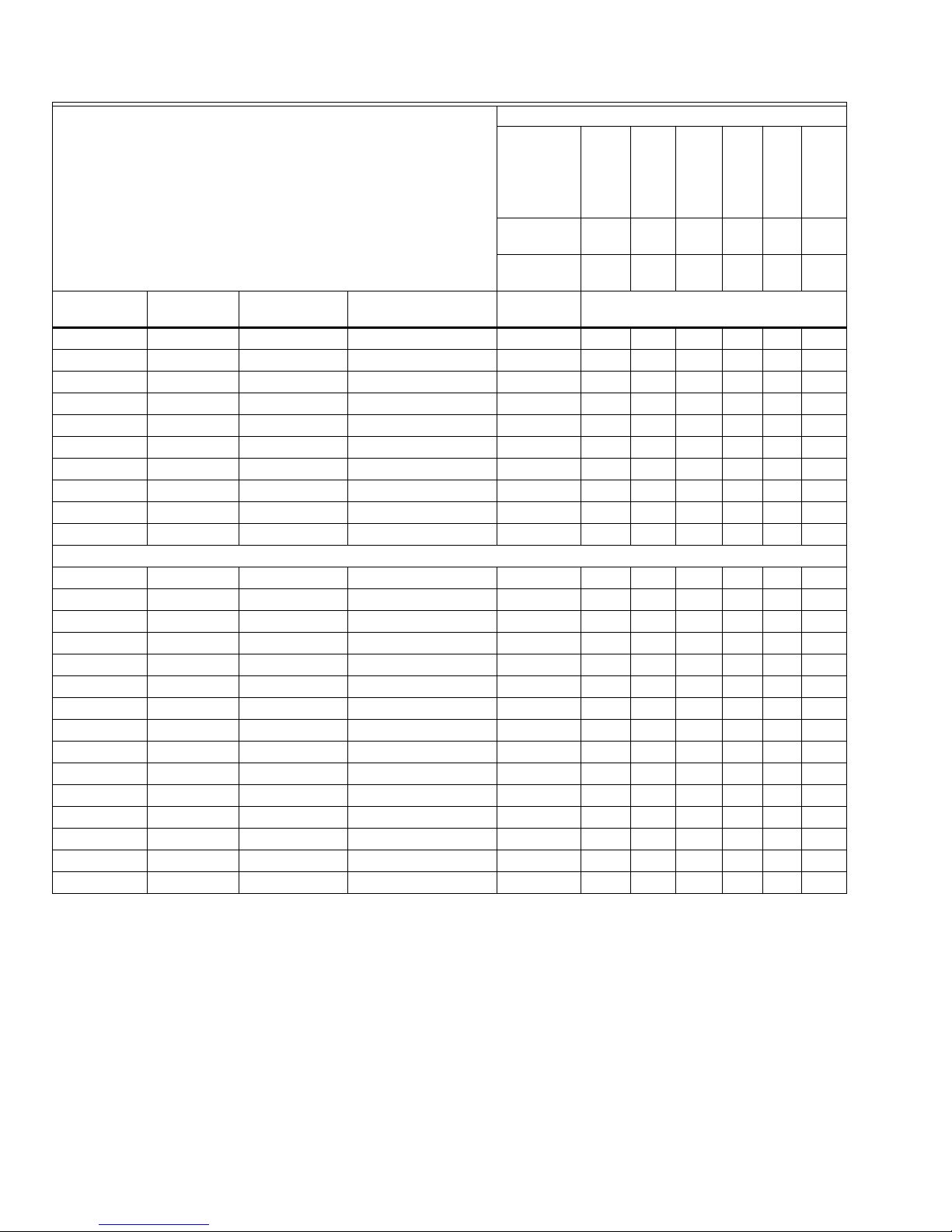
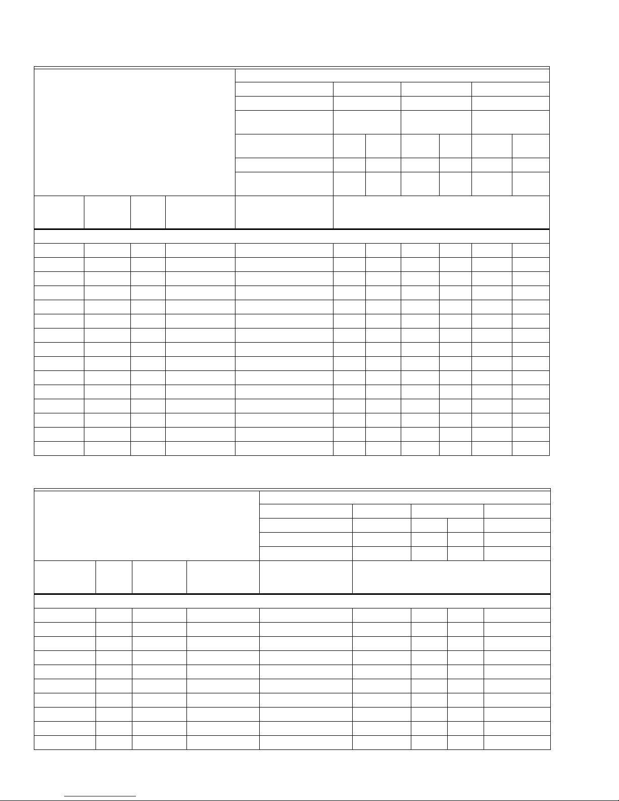
Table 4. Close-off Ratings for VGF valves and Linear Actuators.
Linear Globe Valve Actuator Models
Actuator Part
Number
ML6420A3049
ML6420A3056
ML7420A3055
ML7420A3063
ML6425A3022
ML7425A3013
ML6421A1017
ML6425B3013
ML7421A1032
ML7425B3012
Stem Force
(lbf) 135 135 135 135 404 404
Actuator
Stroke (inch) 3/4 3/4 3/4 3/4 3/4 1-1/2
Valve Part
Number Close-Off (psi)
Connection Size
(inch)
Valve Characteristics
Stem Travel
(inch) Body Pattern Flow Characteristics
Class 125 Pressure Balanced Globe Valves
2-1/2 3/4 2-Way Equal Percentage VGF21EP25 175 175 175 175 175
3 3/4 2-Way Equal Percentage VGF21EP30 175 175 175 175 175
4 1-1/2 2-Way Equal Percentage VGF21EP40 175
5 1-1/2 2-Way Equal Percentage VGF21EP50 175
6 1-1/2 2-Way Equal Percentage VGF21EP60 175
2-1/2 3/4 2-Way Linear VGF21LP25 175 175 175 175 175
3 3/4 2-Way Linear VGF21LP30 175 175 175 175 175
4 1-1/2 2-Way Linear VGF21LP40 175
5 1-1/2 2-Way Linear VGF21LP50 175
6 1-1/2 2-Way Linear VGF21LP60 175
Class 125 Standard Globe Valves
2-1/2 3/4 2-Way Equal Percentage VGF21ES25 17 17 17 17 68
3 3/4 2-Way Equal Percentage VGF21ES30 7 7 7 7 33
4 1-1/2 2-Way Equal Percentage VGF21ES40 33
5 1-1/2 2-Way Equal Percentage VGF21ES50 13
6 1-1/2 2-Way Equal Percentage VGF21ES60 13
2-1/2 3/4 2-Way Linear VGF21LS25 17 17 17 17 68
3 3/4 2-Way Linear VGF21LS30 7 7 7 7 33
4 1-1/2 2-Way Linear VGF21LS40 33
5 1-1/2 2-Way Linear VGF21LS50 13
6 1-1/2 2-Way Linear VGF21LS60 13
100%10% 20% 30% 40% 50%
ML6421B1040
ML7421B1023
3 63-2618—01
Page 4
VGF FLANGED GLOBE VALVES
Linear Globe Valve Actuator Models
Actuator Part
Number
ML6420A3049
ML6420A3056
ML7420A3055
ML7420A3063
ML6425A3022
ML6425B3013
ML7425A3013
ML7425B3012
ML6421A1017
ML7421A1032
Stem Force
(lbf) 135 135 135 135 404 404
Actuator
Connection Size
(inch)
Valve Characteristics
Stem Travel
(inch) Body Pattern Flow Characteristics
Stroke (inch) 3/4 3/4 3/4 3/4 3/4 1-1/2
Valve Part
Number Close-Off (psi)
2-1/2 3/4 Mixing Equal Percentage * VGF31EM25 23 23 23 23 94
3 3/4 Mixing Equal Percentage * VGF31EM30 15 15 15 15 58
4 1-1/2 Mixing Equal Percentage * VGF31EM40 33
5 1-1/2 Mixing Equal Percentage * VGF31EM50 13
6 1-1/2 Mixing Equal Percentage * VGF31EM60 13
2-1/2 3/4 Diverting Linear VGF31LD25 17 17 17 17 68
3 3/4 Diverting Linear VGF31LD30 7 7 7 7 33
4 1-1/2 Diverting Linear VGF31LD40 33
5 1-1/2 Diverting Linear VGF31LD50 13
6 1-1/2 Diverting Linear VGF31LD60 13
Class 250 Standard Globe Valves
2-1/2 3/4 2-Way Equal Percentage VGF22ES25 17 17 17 17 68
3 3/4 2-Way Equal Percentage VGF22ES30 7 7 7 7 33
4 1-1/2 2-Way Equal Percentage VGF22ES40 33
5 1-1/2 2-Way Equal Percentage VGF22ES50 13
6 1-1/2 2-Way Equal Percentage VGF22ES60 13
2-1/2 3/4 Mixing Equal Percentage * VGF32EM25 23 23 23 23 94
3 3/4 Mixing Equal Percentage * VGF32EM30 15 15 15 15 58
4 1-1/2 Mixing Equal Percentage * VGF32EM40 33
5 1-1/2 Mixing Equal Percentage * VGF32EM50 13
6 1-1/2 Mixing Equal Percentage * VGF32EM60 13
2-1/2 3/4 Diverting Linear VGF32LD25 17 17 17 17 68
3 3/4 Diverting Linear VGF32LD30 7 7 7 7 33
4 1-1/2 Diverting Linear VGF32LD40 33
5 1-1/2 Diverting Linear VGF32LD50 13
6 1-1/2 Diverting Linear VGF32LD60 13
* Mixing valves B-port have linear flow characteristics.
ML6421B1040
ML7421B1023
63-2618—01 4
Page 5
VGF FLANGED GLOBE VALVES
Table 5. Close-off Ratings for VGF valves with Direct Coupled Actuators and Linkages.
Rotary Direct Coupled Actuators with Globe Valve Linkage
Linkage Part Number Q5020A1003 Q5024B2230 Q5024B2240
Linkage Type Single actuator Dual actuator Dual actuator
Stem Adapter / Collar Part
Number N/A HU5024-001 HU5024-002
Actuator torque (lb-in) 175 300
350
(2x175)
600
(2x300)
350
(2x175)
(2x300)
Stem Force (lbf) 234 402 360 617 272 467
Effective Linkage Stroke
Valve Characteristics
(inch) 3/4 3/4 3/4 3/4 1-1/2 1-1/2
Connection
Size
(inch)
Stem Travel
(inch)
Body
Pattern
Flow
characteristics Valve Part Number Close-Off (psi)
Class 125 Pressure Balanced Globe Valves
2-1/2 3/4 2-Way Equal Percentage VGF21EP25 175 175 175 175
3 3/4 2-Way Equal Percentage VGF21EP30 175 175 175 175
4 1-1/2 2-Way Equal Percentage VGF21EP40 175 175
5 1-1/2 2-Way Equal Percentage VGF21EP50 175 175
6 1-1/2 2-Way Equal Percentage VGF21EP60 175 175
2-1/2 3/4 2-Way Linear VGF21LP25 175 175 175 175
3 3/4 2-Way Linear VGF21LP30 175 175 175 175
4 1-1/2 2-Way Linear VGF21LP40 175 175
5 1-1/2 2-Way Linear VGF21LP50 175 175
6 1-1/2 2-Way Linear VGF21LP60 175 175
Class 125 Standard Globe Valves
2-1/2 3/4 2-Way Equal Percentage VGF21ES25 39 68 61 105
3 3/4 2-Way Equal Percentage VGF21ES30 19 33 30 52
4 1-1/2 2-Way Equal Percentage VGF21ES40 22 39
5 1-1/2 2-Way Equal Percentage VGF21ES50 9 15
6 1-1/2 2-Way Equal Percentage VGF21ES60 9 15
2-1/2 3/4 2-Way Linear VGF21LS25 39 68 61 105
3 3/4 2-Way Linear VGF21LS30 19 33 30 52
4 1-1/2 2-Way Linear VGF21LS40 22 39
5 1-1/2 2-Way Linear VGF21LS50 9 15
6 1-1/2 2-Way Linear VGF21LS60 9 15
2-1/2 3/4 Mixing Equal Percentage * VGF31EM25 55 94 77 133
3 3/4 Mixing Equal Percentage * VGF31EM30 34 58 52 89
4 1-1/2 Mixing Equal Percentage * VGF31EM40 22 39
5 1-1/2 Mixing Equal Percentage * VGF31EM50 9 15
6 1-1/2 Mixing Equal Percentage * VGF31EM60 9 15
2-1/2 3/4 Diverting Linear VGF31LD25 39 68 61 105
3 3/4 Diverting Linear VGF31LD30 19 33 30 52
4 1-1/2 Diverting Linear VGF31LD40 22 39
5 1-1/2 Diverting Linear VGF31LD50 9 15
6 1-1/2 Diverting Linear VGF31LD60 9 15
600
5 63-2618—01
Page 6
VGF FLANGED GLOBE VALVES
Rotary Direct Coupled Actuators with Globe Valve Linkage
Linkage Part Number Q5020A1003 Q5024B2230 Q5024B2240
Linkage Type Single actuator Dual actuator Dual actuator
Stem Adapter / Collar Part
Number N/A HU5024-001 HU5024-002
Actuator torque (lb-in) 175 300
350
(2x175)
600
(2x300)
350
(2x175)
Stem Force (lbf) 234 402 360 617 272 467
Effective Linkage Stroke
Valve Characteristics
(inch) 3/4 3/4 3/4 3/4 1-1/2 1-1/2
Connection
Size
(inch)
Stem Travel
(inch)
Body
Pattern
Flow
characteristics Valve Part Number Close-Off (psi)
Class 250 Standard Globe Valves
2-1/2 3/4 2-Way Equal Percentage VGF22ES25 39 68 61 105
3 3/4 2-Way Equal Percentage VGF22ES30 19 33 30 52
4 1-1/2 2-Way Equal Percentage VGF22ES40 22 39
5 1-1/2 2-Way Equal Percentage VGF22ES50 9 15
6 1-1/2 2-Way Equal Percentage VGF22ES60 9 15
2-1/2 3/4 Mixing Equal Percentage * VGF32EM25 55 94 77 133
3 3/4 Mixing Equal Percentage * VGF32EM30 34 58 52 89
4 1-1/2 Mixing Equal Percentage * VGF32EM40 22 39
5 1-1/2 Mixing Equal Percentage * VGF32EM50 9 15
6 1-1/2 Mixing Equal Percentage * VGF32EM60 9 15
2-1/2 3/4 Diverting Linear VGF32LD25 39 68 61 105
3 3/4 Diverting Linear VGF32LD30 19 33 30 52
4 1-1/2 Diverting Linear VGF32LD40 22 39
5 1-1/2 Diverting Linear VGF32LD50 9 15
6 1-1/2 Diverting Linear VGF32LD60 9 15
* Mixing valves B-port have linear flow characteristics.
600
(2x300)
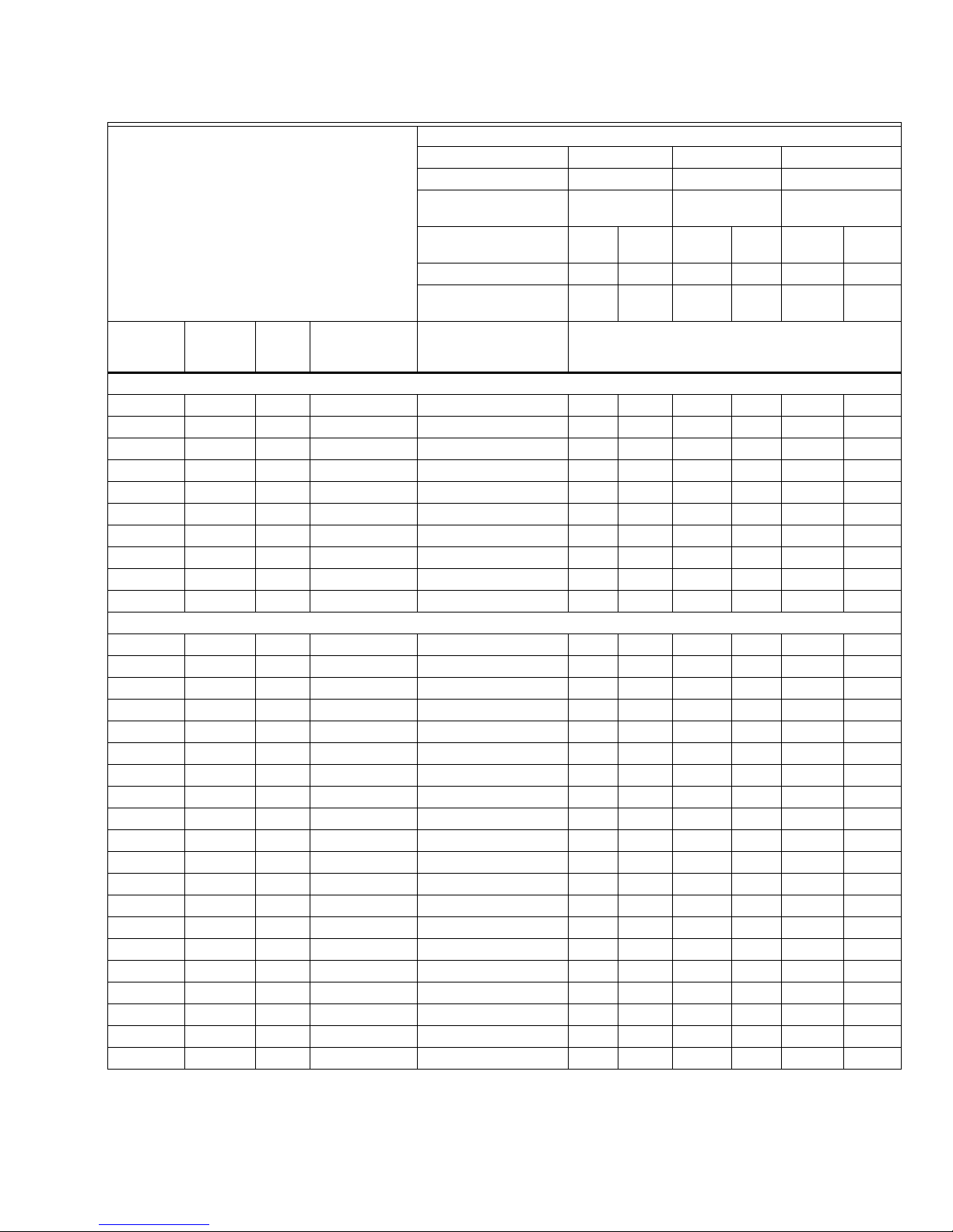
Table 6. Close-off Ratings for VGF valves with Modutrol IV Actuators and Linkages.
Modutrol IV Actuators with Q5001 Valve Linkage
Linkage Part Number Q5001D1000 Q5001D1018 Q5001D1026
Actuator torque (lb-in) 150 150 300 300
Stem Force (lbf) 160 160 320 320
Valve Characteristics
Linkage Stroke (inch) 3/4 3/4 3/4 1-1/2
Stem
Connection Size
(inch)
Tra vel
(inch) Body Pattern Flow characteristics Valve Part Number Close-Off (psi)
Class 125 Pressure Balanced Globe Valves
2-1/2 3/4 2-Way Equal Percentage VGF21EP25 175 175 175
3 3/4 2-Way Equal Percentage VGF21EP30 175 175 175
4 1-1/2 2-Way Equal Percentage VGF21EP40 175
5 1-1/2 2-Way Equal Percentage VGF21EP50 175
6 1-1/2 2-Way Equal Percentage VGF21EP60 175
2-1/2 3/4 2-Way Linear VGF21LP25 175 175 175
3 3/4 2-Way Linear VGF21LP30 175 175 175
4 1-1/2 2-Way Linear VGF21LP40 175
5 1-1/2 2-Way Linear VGF21LP50 175
6 1-1/2 2-Way Linear VGF21LP60 175
63-2618—01 6
Page 7

VGF FLANGED GLOBE VALVES
Modutrol IV Actuators with Q5001 Valve Linkage
Linkage Part Number Q5001D1000 Q5001D1018 Q5001D1026
Actuator torque (lb-in) 150 150 300 300
Stem Force (lbf) 160 160 320 320
Valve Characteristics
Linkage Stroke (inch) 3/4 3/4 3/4 1-1/2
Stem
Connection Size
(inch)
Tra vel
(inch) Body Pattern Flow characteristics Valve Part Number Close-Off (psi)
Class 125 Standard Globe Valves
2-1/2 3/4 2-Way Equal Percentage VGF21ES25 27 27 55
3 3/4 2-Way Equal Percentage VGF21ES30 13 13 27
4 1-1/2 2-Way Equal Percentage VGF21ES40 27
5 1-1/2 2-Way Equal Percentage VGF21ES50 10
6 1-1/2 2-Way Equal Percentage VGF21ES60 10
2-1/2 3/4 2-Way Linear VGF21LS25 27 27 55
3 3/4 2-Way Linear VGF21LS30 13 13 27
4 1-1/2 2-Way Linear VGF21LS40 27
5 1-1/2 2-Way Linear VGF21LS50 10
6 1-1/2 2-Way Linear VGF21LS60 10
2-1/2 3/4 Mixing Equal Percentage * VGF31EM25 34 34 69
3 3/4 Mixing Equal Percentage * VGF31EM30 23 23 46
4 1-1/2 Mixing Equal Percentage * VGF31EM40 27
5 1-1/2 Mixing Equal Percentage * VGF31EM50 10
6 1-1/2 Mixing Equal Percentage * VGF31EM60 10
2-1/2 3/4 Diverting Linear VGF31LD25 27 27 55
3 3/4 Diverting Linear VGF31LD30 13 13 27
4 1-1/2 Diverting Linear VGF31LD40 27
5 1-1/2 Diverting Linear VGF31LD50 10
6 1-1/2 Diverting Linear VGF31LD60 10
Class 250 Standard Globe Valves
2-1/2 3/4 2-Way Equal Percentage VGF22ES25 27 27 55
3 3/4 2-Way Equal Percentage VGF22ES30 13 13 27
4 1-1/2 2-Way Equal Percentage VGF22ES40 27
5 1-1/2 2-Way Equal Percentage VGF22ES50 10
6 1-1/2 2-Way Equal Percentage VGF22ES60 10
2-1/2 3/4 Mixing Equal Percentage * VGF32EM25 34 34 69
3 3/4 Mixing Equal Percentage * VGF32EM30 23 23 46
4 1-1/2 Mixing Equal Percentage * VGF32EM40 27
5 1-1/2 Mixing Equal Percentage * VGF32EM50 10
6 1-1/2 Mixing Equal Percentage * VGF32EM60 10
2-1/2 3/4 Diverting Linear VGF32LD25 27 27 55
3 3/4 Diverting Linear VGF32LD30 13 13 27
4 1-1/2 Diverting Linear VGF32LD40 27
5 1-1/2 Diverting Linear VGF32LD50 10
6 1-1/2 Diverting Linear VGF32LD60 10
* Mixing valves B-port have linear flow characteristics.
7 63-2618—01
Page 8

VGF FLANGED GLOBE VALVES
M22409
D
A
C
B
1
DOTTED LINE REPRESENTS ANSI 125
VALVE BONNET.
1
E
Stroke Y
Table 7. VGF3 B-Port Threads.
Model Thread # of Holes
VGF31EM25 0.625-11 4
VGF31EM30 0.625-11 4
VGF31EM40 0.625-11 8
VGF31EM50 0.750-10 8
VGF31EM60 0.750-10 8
VGF32EM25 0.750-10 8
VGF32EM30 0.750-10 8
VGF32EM40 0.750-10 8
VGF32EM50 0.750-10 8
VGF32EM60 0.750-10 12
VGF31LD25 0.625-11 4
VGF31LD30 0.625-11 4
VGF31LD40 0.625-11 8
VGF31LD50 0.750-10 8
VGF31LD60 0.750-10 8
VGF32LD25 0.750-10 8
VGF32LD30 0.750-10 8
VGF32LD40 0.750-10 8
VGF32LD50 0.750-10 8
VGF32LD60 0.750-10 12
Stroke Y
E
B
C
D
A
DOTTED LINE REPRESENTS ANSI 125
1
VALVE BODY.
M22420
Fig. 3. Dimensions for two-way models in inches (mm)
(See Table 8).
IMPORTANT
Valve sizing is important for correct system operation. Undersized valves do not have sufficient
capacity at maximum load. Oversized valves do not
have sufficient authority over the load in modulating applications.
Oversized valves can initiate hunting and the seat
and throttling plug can be damaged because of
the restricted opening. Some variables that must
be determined are:
•Medium (steam, water, glycol solution 50 percent
•Maximum temperature and pressure of the
•Pressure differential that exists across the valve
•Maximum capacity the valve must deliver.
•Maximum line pressure differential against which
maximum) to be controlled.
medium at the valve.
under maximum load conditions.
the valve actuator must close.
Fig. 4. Dimensions for three-way models in inches (mm)
(See Table 8).
63-2618—01 8
Page 9

VGF FLANGED GLOBE VALVES
Table 8. Valve Sizes, Flow Capacities, and Dimensions.
Dimensions, in. (mm)
Model
Number
Size
in. DN A B C D E
Cv (kvs)
See Fig. 3 (Two-way Valves) or Fig. 4 (Three-way Valves)
a
Y (stroke)
2-way valves, ANSI Class 125 Stem down to close. Equal percentage or Linear flow characteristic.
VGF21_S25 2-1/2 65 70 (60) 10-7/8 (276) 4-3/8 (112) 7 (178) —
VGF21_S30 3 80 125 (108) 11-3/4 (298) 6-3/8 (161) 7-1/2 (191) —
3-1/2 (89) 3/4 (19)
VGF21_S40 4 100 155 (133) 13-7/8 (352) 5-7/8 (150) 9 (229) —
5-1/4 (133) 1-1/2 (38)VGF21_S50 5 125 320 (275) 15-3/4 (400) 6-3/16 (157) 10 (254) —
VGF21_S60 6 150 370 (318) 17-3/4 (451) 6-3/16 (157) 11 (279) —
2-way valves, ANSI Class 250. Stem down to close. Equal percentage flow characteristic.
VGF22ES25 2-1/2 65 70 (60) 11-1/2 (292) 4-3/8 (112) 7-1/2 (191) —
VGF22ES30 3 80 120 (103) 12-1/2 (318) 6-3/8 (161) 8-1/4 (210) —
3-1/2 (89) 3/4 (19)
VGF22ES40 4 100 150 (129) 14-1/2 (368) 5-7/8 (150) 10 (254) —
5-1/4 (133) 1-1/2 (38)VGF22ES50 5 125 320 (275) 16-5/8 (422) 6-3/16 (157) 11 (279) —
VGF22ES60 6 150 370 (318) 18-5/8 (473) 6-3/16 (157) 12-1/2 (318) —
2-way valves, Pressure-balanced, ANSI Class 125. Stem down to close. Equal percentage or Linear flow characteristic.
VGF21_P25 2-1/2 65 70 (60) 10-7/8 (276) 4-3/16 (107) 7 (178) —
VGF21_P30 3 80 115 (99) 11-3/4 (298) 5-7/8 (150) 7-1/2 (191) —
3-1/2 (89) 3/4 (19)
VGF21_P40 4 100 150 (129) 13-7/8 (352) 5-7/8 (150) 9 (229) —
5-1/4 (133) 1-1/2 (38)VGF21_P50 5 125 285 (245) 15-3/4 (400) 6-1/8 (156) 10 (254) —
VGF21_P60 6 150 370 (318) 17-3/4 (451) 6-1/8 (156) 11 (279) —
3-way Mixing valves, ANSI Class 125. Stem up to close A-AB.
VGF31EM25 2-1/2 65 70 (60) 10-7/8 (276) 3-15/16 (100) 7 (178) 3-3/4 (95)
VGF31EM30 3 80 120 (103) 11-3/4 (298) 3-15/16 (100) 7-1/2 (191) 4-3/8 (111)
4-3/16 (107) 3/4 (19)
VGF31EM40 4 100 150 (129) 13-7/8 (352) 5-8/16 (140) 9 (229) 5-1/8 (130)
6-11/16 (170) 1-1/2 (38)VGF31EM50 5 125 320 (275) 15-3/4 (400) 5-3/8 (137) 10 (254) 5-3/4 (146)
VGF31EM60 6 150 370 (318) 17-3/4 (451) 5-11/16 (145) 11 (279) 6-5/8 (168)
3-way Mixing valves, ANSI Class 250. Stem up to close A-AB.
VGF32EM25 2-1/2 65 70 (60) 11-1/2 (292) 4-3/8 (112) 7-1/2 (191) 3-3/4 (95)
VGF32EM30 3 80 115 (99) 12-1/2 (318) 6-3/8 (161) 8-1/4 (210) 4-3/8 (111)
4-3/16 (107) 3/4 (19)
VGF32EM40 4 100 170 (146) 14-1/2 (368) 5-7/8 (150) 10 (254) 5-1/8 (130)
6-11/16 (170) 1-1/2 (38)VGF32EM50 5 125 320 (275) 16-5/8 (422) 6-3/16 (157) 11 (279) 5-3/4 (146)
VGF32EM60 6 150 370 (318) 18-5/8 (473) 6-3/16 (157) 12-1/2 (318) 6-5/8 (168)
3-way Diverting valves, ANSI Class 125. Stem down to close AB-A.
VGF31LD25 2-1/2 65 70 (60) 10-7/8 (276) 3-15/16 (100) 7 (178) 3-3/4 (95)
VGF31LD30 3 80 120 (103) 11-3/4 (298) 3-15/16 (100) 7-1/2 (191) 4-3/8 (111)
4-3/16 (107) 3/4 (19)
VGF31LD40 4 100 160 (138) 13-7/8 (352) 5-8/16 (140) 9 (229) 5-1/8 (130)
6-11/16 (170) 1-1/2 (38)VGF31LD50 5 125 285 (245) 15-3/4 (400) 5-3/8 (137) 10 (254) 5-3/4 (146)
VGF31LD60 6 150 380 (327) 17-3/4 (451) 5-11/16 (145) 11 (279) 6-5/8 (168)
3-way Diverting valves, ANSI Class 250. Stem down to close AB-A.
VGF32LD25 2-1/2 65 70 (60) 11-1/2 (292) 4-3/8 (112) 7-1/2 (191) 3-3/4 (95)
VGF32LD30 3 80 120 (103) 12-1/2 (318) 6-3/8 (161) 8-1/4 (210) 4-3/8 (111)
4-3/16 (107) 3/4 (19)
VGF32LD40 4 100 160 (138) 14-1/2 (368) 5-7/8 (150) 10 (254) 5-1/8 (130)
6-11/16 (170) 1-1/2 (38)VGF32LD50 5 125 285 (245) 16-5/8 (422) 6-3/16 (157) 11 (279) 5-3/4 (146)
VGF32LD60 6 150 380 (327) 18-5/8 (473) 6-3/16 (157) 12-1/2 (318) 6-5/8 (168)
a
With stem fully down.
9 63-2618—01
Page 10

VGF FLANGED GLOBE VALVES
12
(83)
13
(90)
14
(96)
15
(103)
16
(110)
17
(117)
18
(124)
19
(131)
20
(138)
21
(144)
22
(152)
23
(159)
24
(165)
25
(172)
12
(83)
11
(76)
13
(90)
14
(96)
15
(103)
16
(110)
17
(117)
18
(124)
12
(83)
11
(76)
13
(90)
14
(96)
15
(103)
16
(110)
17
(117)
18
(124)
19
(131)
20
(138)
21
(144)
22
(152)
23
(159)
24
(165)
25
(172)
19
(131)
20
(138)
21
(144)
22
(152)
23
(159)
24
(165)
25
(172)
7
(48)
8
(55)
9
(62)
10
(69)
0
(0)10(69)20(138)30(207)
40
(276)
60
(414)70(483)
50
(345)
80
(552)90(621)
100
(690)
110
(759)
120
(828)
130
(897)
140
(966)
150
(1035)
160
(1104)
2-7
(15-50)
4-11
(30-75)
8-12
(55-85)
SPRING RANGE
PSI (kPa)
SIZE 2-1/2 IN. AND 3 IN.
WITH 8 IN. D.A. PNEUMATIC ACTUATOR
(NORMALLY OPEN PORTS B TO AB)
AIR PRESSURE IN ACTUATOR PSI (kPa)
CLOSEOFF PRESSURE RATINGS PSI (kPa)
CLOSEOFF PRESSURE AT VARIOUS CONTROL AIR PRESSURES FOR VGF FLANGED VALVES AND MP953 PNEUMATIC ACTUATORS.
AIR PRESSURE REQUIRED TO OPERATE PRESSURE-BALANCED VGF FLANGED VALVES.
1
2
1
SIZE 2-1/2 INCH
SIZE 3 INCH
M36506
2 2
2
(15)
1
(5)
0
(0)
L*
U**
*L - LOWER SEAT
**U - UPPER SEAT
4
(30)
3
(20)
2
(15)
1
(5)
0
(0)
8
(55)
7
(50)
6
(40)
5
(35)
4
(30)
3
(20)
2
(15)
1
(5)
0
(0)
L*
U**
L*
U**
SPRING RANGE
2-7
(15-50)
7
2
(48)
(15)
1
8
(5)
(55)
9
0
(62)
(0)
10
(69)
11
(76)
12
(83)
13
(90)
AIR PRESSURE IN ACTUATOR PSI (kPa)
14
(96)
15
(103)
L*
U**
*L - LOWER SEAT
**U - UPPER SEAT
PSI (kPa)
(76)
(83)
13
(90)
(96)
(103)
(110)
(117)
(124)
(131)
1
SIZE 2-1/2 AND 3 IN. D.A. FLANGED BODIES
8-12
4-11
(55-85)
(30-75)
12
8
4
11
(83)
(55)
(30)
13
7
3
12
(90)
(50)
(20)
14
6
2
(96)
(40)
(15)
15
14
15
16
17
18
19
L*
5
1
(103)
(35)
(5)
4
0
16
(30)
(0)
(110)
17
3
(117)
(20)
2
18
(15)
(124)
1
19
(5)
(131)
0
20
(0)
(138)
0
(0)
L*
U**
U**
1
WITH 7 IN. R.A. PNEUMATIC ACTUATOR
(NORMALLY CLOSED)
SIZE 2-1/2 INCH
SIZE 3 INCH
25
(172)
30
(207)
35
(241)
40
(276)
10
5
(69)
(35)
USE 8-13 PSI (55-90 kPa) RANGE FOR DETERMINING CLOSEOFF OF VALVES
USED WITH MP953F ACTUATORS.
20
15
(138)
(104)
CLOSEOFF PRESSURE RATINGS PSI (kPa)
(310)
50
45
(345)
55
(379)
Fig. 5. Close-off pressures with 7 in. RA Pneumatic Actuator.
60
(414)
M36642
63-2618—01 10
Fig. 6. Close-off pressures with 8 in. D.A. pneumatic actuators.
Page 11

VGF FLANGED GLOBE VALVES
WARNING
SIZE 2-1/2 IN., 3 IN., 4 IN., 5 IN., 6 IN.
WITH 13 IN. D.A. PNEUMATIC ACTUATOR
(NORMALLY OPEN PORTS B TO AB)
CLOSEOFF PRESSURE RATINGS PSI (kPa)
SIZE 2-1/2 INCH
SIZE 3- AND 4-INCH
M36643
SIZE 5- AND 6-INCH
CLOSEOFF PRESSURE AT VARIOUS CONTROL AIR PRESSURES FOR
VGF FLANGED VALVES AND MP953 PNEUMATIC ACTUATORS.
AIR PRESSURE REQUIRED TO OPERATE PRESSURE-BALANCED VGF VALVES.
1
2
0
(0)10(69)20(138)30(207)
40
(276)
60
(414)70(483)
50
(345)
80
(552)90(621)
100
(690)
110
(759)
120
(828)
130
(897)
140
(966)
150
(1035)
160
(1104)
2 2 2
12
(83)
13
(90)
14
(96)
15
(103)
16
(110)
17
(117)
18
(124)
19
(131)
20
(138)
21
(144)
22
(152)
23
(159)
24
(165)
25
(172)
12
(83)
11
(76)
13
(90)
14
(96)
15
(103)
16
(110)
17
(117)
18
(124)
12
(83)
11
(76)
13
(90)
14
(96)
15
(103)
16
(110)
17
(117)
18
(124)
19
(131)
20
(138)
21
(144)
22
(152)
23
(159)
24
(165)
25
(172)
19
(131)
20
(138)
21
(144)
22
(152)
23
(159)
24
(165)
25
(172)
7
(48)
8
(55)
9
(62)
10
(69)
2-7
(15-50)
4-11
(30-75)
8-12
(55-85)
SPRING RANGE
PSI (kPa)
AIR PRESSURE IN ACTUATOR PSI (kPa)
1
2
(15)
1
(5)
0
(0)
L*
U**
*L - LOWER SEAT
**U - UPPER SEAT
4
(30)
3
(20)
2
(15)
1
(5)
0
(0)
8
(55)
7
(50)
6
(40)
5
(35)
4
(30)
3
(20)
2
(15)
1
(5)
0
(0)
L*
U**
L*
U**
INSTALLATION
When Installing this Product...
1. Read these instructions carefully. Failure to follow
them could damage the product or cause a hazardous condition.
2. Check ratings given in instructions and on the prod-
uct to ensure the product is suitable for your application.
3. Installer must be a trained, experienced service
technician.
Fig. 7. Close-off pressures with 13 in. D.A pneumatic actuators.
4. After installation is complete, check out product
operation as provided in these instructions.
Severe Burn Hazard.
Contact with hot liquid can lead to severe injury
or cause death.
Release system pressure and isolate or drain the
valve pipe section so the medium (steam, water or
glycol solution) does not leak out of the valve body
during installation (see Fig. 9).
11 63-2618—01
Page 12

VGF FLANGED GLOBE VALVES
CAUTION
M22590
M22592
133 IN-LB
(15 NM)
M22593
Electrical Shock or Equipment Damage Hazard.
Can shock individuals or short equipment
circuitry.
Disconnect power supply to the actuator to prevent
electrical shock and equipment damage, or
remove and cap the air line to the actuator.
IMPORTANT
• Before installing the valve, raise and lower the
valve stem to make sure that the valve stem operates freely. Impaired stem operation can indicate
that the stem was bent by rough handling. This
condition can require replacing the valve.
• Protect the stem from damage due to bending or
scratching.
NOTES:
• Some non-pressure balanced valves have stem travel
greater than the published 3/4 in. (20 mm) or 1-1/2 in.
(38 mm) control stroke. This is due to use of bodies
shared with pressure-balanced models.
• The first 3/4 inch (20mm) of the stroke is the control
stroke of the 2-1/2 and 3 inch valves.
• The first 1-1/2 inch (38 mm) of stroke is the control
stroke of the 4 to 6 inch valves.
Proper Use
These valves are only for use in cold, warm, hot water
systems and for steam applications. They are designed for
the medium temperature ranges listed in the
specifications. They are to be operated with the
appropriate Honeywell actuators only. Water should be
properly filtered, treated and conditioned according to
local conditions. The installation of a strainer is strongly
recommended.
IMPORTANT
The presence of iron oxide (red rust) in the system
voids the valve warranty. The use of rust inhibitors
is recommended.
Safety
The valves are to be installed by skilled personnel and in
strict accordance with the installation instructions and
local regulations. (See Fig. 8 for proper hoisting method.)
Honeywell assumes no responsibility for damages or
injuries resulting from non-compliance with installation
instructions or standard good practice when mounting,
operating, or maintaining the valves, even if not explicitly
mentioned in the installation instructions. (See Fig. 10 for
basic pipe orientation.) Observe all safety practices when
working with steam systems.
Fig. 10. Basic pipe orientation.
Fig. 8. Proper hoisting of VGF Valves.
M22591
Fig. 9. Piping must prevent leakage.
63-2618—01 12
Fig. 11. Basic proper bolt length.
Page 13

VGF FLANGED GLOBE VALVES
COMPANION
FLANGE
GASKET
GASKET
GASKET
BE SURE FACE OF COMPANION FLANGE IS FLUSH
WITH FACE OF VALVE-BODY FLANGE AND ALIGNED
SQUARELY BEFORE TIGHTENING MOUNTING NUTS.
OPTIONAL SERVICE FLANGE
COMPANION FLANGE
PIPE
M7977
Location
Select a location where the valve and actuator are
accessible. Allow sufficient space for servicing the valve
and actuator. See Fig. 3 and 4 for valve body dimensions.
7. Use mounting bolts long enough so the nuts can use
the full length of the nut threads. (See Fig. 11.) Use
bolts 1/8 in. smaller than the diameter of the bolt
hole to allow clearance for installing. (See Fig. 12.)
Mounting Actuator
For information on mounting, refer to the Product Data
literature for the actuator. It is important to have the
correct actuator available for the installation. See Table 9
for recommended installation clearance from valve
bonnet.
IMPORTANT
When using VGF valves with pneumatic MP953C
and MP953E direct acting actuators, the following
stroke limiting accessories are required to prevent
over-travel and damage to the diaphragm. See Fig.
21:
• VGF21ES25 - 272629A (stem collar, purchased
separately)
• VGF21ES30 - 272629A (stem collar, purchased
separately)
• VGF21LS25 - 272629A (stem collar, purchased
separately)
• VGF21LS30 - 272629A (stem collar, purchased
separately)
• VGF31EM25 - stem collar (provided with valve)
• VGF31EM30 - stem collar (provided with valve)
Fig. 12. Flanged valve body installation.
Mounting the Valve
See Fig. 12 for typical installation.
1. Hoist valve by its body only. Do not lift by stem, bon-
net, flanges, or flange holes. (See Fig. 8.)
2. Install the valve so the flow follows the direction of
3. Install the valve so the actuator is above the valve
4. When controlling steam, use appropriate high
5. Use companion flanges with the same number of
6. Use a gasket material recommended for the medium
the arrow indicated on the valve body.
body. The valve can be installed in any position
between vertical and horizontal. Do not install the
valve with the stem below horizontal or upside down.
temperature kit 43196000 and rotate valve body so
that actuator is not positioned directly above the
piping.
bolt holes and dimensions as the valve to be
installed. (See Table 7.) Use standard cast-iron
flanges for the two end ports.
to be handled.
Table 9. Installation Clearances (from Valve Bonnet).
Actuator Minimum Vertical Clearance in in. (mm)
ML6420, ML7420 12-11/16 (322)
ML6421A, ML7421A 14-1/4 (360)
ML6421B, ML7421B 16-7/8 (430)
ML6425A,B; ML7425A,B 14-5/16 (364)
MN/MS Series + Q5020 12 (305)
Modutrol IV + Q5001 14-1/2 (369)
MP953C (8 inch dia) 11-7/8 (302)
MP953C (13 inch dia) 17-11/16 (449)
MP953E (8 inch dia) 16-1/2 (420)
MP953E (13 inch dia) 25-13/16 (655)
MN/MS Series + Q5024 18 (457)
CHECKOUT
For instructions for operating the valve actuator, see the
Product Data sheet for the specific actuator.
1. Operate the control system and check valve opera-
tion to ensure the valve stem can position the valve
smoothly through full stroke without binding.
2. Verify that the actuator fully closes the A port.
3. Perform the checkout tests included with the actua-
tor instructions.
13 63-2618—01
Page 14

VGF FLANGED GLOBE VALVES
2
4
3
1
MP953E
MP953C
POSITIONER
ON MP953E ONLY
MINUMUM
CLEARANCE
MP953C, E
1 2 3
4
M7993B
OPERATION SIZE
NOMINAL DIA
8-INCH
13-INCH
8-1/4 (210)
13-1/2 (343)
11-1/8 (283)
18-1/8 (460)
6-1/2 (165)
10 (254)
5-3/8 (137)
7-11/16 (195)
2-1/2
(64)
7 (178 ) X 7 (178)
5-5/8
(142)
KNOCKOUTS
(2)
7/8 (22)
9-3/8
(239)
10-3/8
(264)
14-1/4
(360)
MINIMUM
CLEARANCE
ML6421A
YOKE DIAMETER 1-3/8 (35)
M7978
ML6421B
2-1/2
(64)
7 (178 ) X 7 (178)
KNOCKOUTS
(2)
7/8 (22)
8
(204)
11-7/8
(301)
CLEARANCE
12-3/4
(326)
16-7/8
(430)
MINIMUM
Fig. 13. MP953C-F Pneumatic Actuator
dimensions in in. (mm).
YOKE DIAMETER 1-7/8 (48)
M7979
Fig. 15. ML6421B and ML7421B Actuator (use with
4, 5, and 6 in. valves) dimensions in in. (mm).
Fig. 14. ML6421A and ML7421A Actuator (use with
2-1/2 and 3 in. valves) dimensions in in. (mm).
63-2618—01 14
Page 15

Fig. 16. ML6425A,B; ML7425A,B Actuator (use with
5-5/15
(135)
6-5/16
(161)
x
2-11/16 (67)
14-5/16 (364)
MINIMUM
CLEARANCE
11-1/4
(284)
7-5/8
(192)
M7892A
1/2 (13) FPT
YOKE
DIAMETER
1-3/8 (35)
4-5/8 (117)
9-1/2
(241)
6-9/16
(166)
1-7/8
(48)
11Q5020A,B,D: 4-7/16 (112)
Q5020C: 3-7/8 (98)
M16346A
2-1/2 and 3 in. valves) dimensions in in. (mm).
VGF FLANGED GLOBE VALVES
Fig. 17. Q5020 Actuator Linkage dimensions in in. (mm).
Q5024B2230/Q5024B2240
E
B
A
D
C
M36664
Linkage A B C D E Shaft Dia.
Q5024B2230
Q5024B2240
4-3/8” 4” 6” 11” 2-3/8” 19mm
Fig. 18. Q5024 Dimensions.
15 63-2618—01
Page 16

VGF FLANGED GLOBE VALVES
OPERATION
Two-Way Valves
Figs. 19 and 20 shows 2-way valves in the fully closed
position.
Pressure-Balanced Valve (Fig. 19)
The pressure-balanced design combines close-off
pressures comparable to a ball valve with traditional globe
valve flow control accuracy in large valve body sizes.
The pressure-balanced valve seat includes a sealed
pressure chamber. These valves operate as follows:
1. With the valve closed, pressure at the A port is pres-
ent in the chamber that forms the upper section of
the plug.
2. This equalizes the pressure above and below the
seat.
NOTE: As the valve opens/closes, the chamber pressure
equalizes in either direction.
3. As a result, the pressure of the medium does not
affect the ability of the actuator to open/close the
valve. The valve actuator works against only pressure
chamber seal friction.
4. This is particularly useful when the pressure of the
medium undergoes significant variation.
5. Regardless of pressure variation, valve operation is
relatively smooth throughout the travel of the stem.
PRESSUREBALANCED
VALVE
PLUG
A PORT
AB PORT
M22616C
Fig. 19. Two-way pressure-balanced valve operation.
STANDARD
VALVE
PLUG
NOTE: Both equal percentage (VGF21EP) and linear
(VGF21LP) flow characteristics are offered.
Standard Plug Valve (Fig. 20)
These valves have a metal-to-metal seat. As these models
share body castings with the pressure-balanced models,
the full stroke of the valve stem can be greater than the
control stroke dimension. (See dimension Y, in Table 8.)
Dimension Y is measured from the closure of the A port.
Honeywell actuators are constructed to this Y dimension,
and limit stem travel accordingly.
Flow does not increase with stem travel greater than 3/4
in. (20 mm) in 2-1/2 and 3 in. valves,
IMPORTANT
All VGF valves reference their flow and stroke to
the A port; actuators must be configured to provide positive closure of this port.
A PORT
AB PORT
M36096
Fig. 20. Two-way standard valve operation.
Three-Way Valves
Figs. 21 and 22 show 3-way valves in the fully closed
position, with no flow between the A port and AB port.
ELECTRIC CONTROL
Upon power failure:
• Spring return actuators return the valve to its normal
position. This position (open or closed to the A or the B
port) depends on the actuator installation.
• Non-spring return actuators hold the last commanded
position.
PNEUMATIC CONTROL
Upon loss of control air pressure:
• The actuator returns the valve to its normal position.
This position (open or closed to the A or the B port)
depends on the actuator model.
63-2618—01 16
Page 17

VGF FLANGED GLOBE VALVES
A
B PORT
AB PORT
A PORT
M36097
STEM
DOWN
Mixing Valve (Fig. 21)
• As the stem moves downward:
— Flow from port B to AB decreases linearly.
— Flow from port A to AB increases at an equal per-
centage rate.
• As the valve stem moves upward:
— Flow from port B to AB increases.
— Flow from port A to AB decreases.
NOTE: The B port seat of the VGF3_EM valves is con-
structed as a cage, not as a seat, and moves
through the B port. It does not offer tight closeoff. For leakage specifications, see Table 4. B port
flow is at a minimum when stem travel down is
3/4 in. (20 mm) in 2-1/2 and 3 in. mixing valves.
OUTDOOR RESET CONTROL (FIG. 24)
• Connect the A port to a boiler output.
• Connect the B port to the system return.
AIR HANDLING APPLICATIONS (FIG. 23)
• Connect the A port to the output of a coil.
• Connect the B port to the coil bypass.
BOILER/CHILLER BYPASS (FIG. 25)
• VGF mixing valves are not recommended for boiler or
chiller bypass due to B port close-off ratings. Use
diverting model instead.
IMPORTANT
VGF Mixing Valves are assembled through the
lower (B) port. The B port stop collar (see Fig. 21)
holds the stem and plug assembly in the bonnet.
Ensure the stem remains raised while servicing
the valve or installing stem extensions. The stem
collar provides a hard stop for direct-acting
MP953 pneumatic actuators, and should not be
removed.
AIR HANDLING APPLICATIONS (FIG. 26)
• Connect the A port to the coil supply.
• Connect the B port to the system return.
NOTE: The A and B connections may be reversed when
using pneumatic actuators.
STEM
UP
B PORT
STOP COLLAR
PORT
B PORT
1
B PORT STOP COLLAR IS SHIPPED ON VGF31EM25/30
AND VGF32EM25/30 VALVES.
1
AB PORT
M22410C
Fig. 21. VGF31EM mixing valve operation.
NOTE: B port stop collar is shipped on VGF31EM25/30
and VGF32EM25/30 valves.
Note that the full stroke of the valve stem can be greater
than the control stroke dimension, Y, in Table 8, which is
measured from the closure of the A port. Honeywell
actuators are constructed for this Y dimension, and limit
stem travel appropriately.
DIVERTING VALVE (FIG. 22)
• As the valve stem moves downward:
— Flow from port AB to A decreases linearly.
— Flow from port AB to B increases linearly.
• As the valve stem moves upward:
— Flow from port AB to A decreases.
— Flow from port AB to B increases.
OUTDOOR RESET CONTROL (FIG. 25)
• Connect the A port to the building supply.
• Connect the B port to the boiler return.
Fig. 22. VGF31LD diverting valve operation.
17 63-2618—01
Page 18

VGF FLANGED GLOBE VALVES
FULL
HEAT
PROPORTIONED
HEAT
SUPPLY
MAIN
RETURN
MAIN
NO
HEAT
HEATING COIL
VGF3
AB
5 GPM
A
B
5 GPM
AB
5 GPM
A
B
2.5 GPM
2.5 GPM
VGF3
VGF3
AB
5 GPM
A
B
5 GPM
NO FLOW
THROUGH COIL
A
B
C
M36098
VGF31EM
AAB
B
BOILER
Fig. 24. Supply mixing for reset control.
MIXED
DISCHARGE
WATER TO
HEAT LOAD
PUMP
M36099
Fig. 23. Three-way mixing valve operation with coil by-
pass.
BOILER
CHECK
VALVES
B
A
VGF31LD
BYPASS
AB
PUMP
M36100
Fig. 25. Boiler bypass for reset control.
AB PORT A PORT
SUPPLY
RETURN
B PORT
Fig. 26. Three-way valve flow orientation.
COIL
AB PORT A PORT
RETURN
SUPPLY
MIXINGDIVERTING
COIL
B PORT
M13737B
63-2618—01 18
Page 19

CHECKOUT AND TROUBLESHOOTING
VGF FLANGED GLOBE VALVES
Actuators
NOTE: For valve actuator operation instructions, see the
Valve does not move freely
Valve Leak-by • Damage to the plug or seat caused by particulate, wire draw, or steam corrosion requires valve replacement.
Valve stem leaks
Improper Control
Noisy Valve
Actuator Failure in Steam Applications
Product Data sheet for the specific actuator.
Table 10. VGF Valve Checkout and Troubleshooting.
Topic Information
• Possible cause: Contamination. Over time, scale, rust, magnetite, sand, and silt can cause wear of valve components.
• The presence of suspended rust in a hydronic system voids most industry warranties.
• Appropriate system flushing, filtration, and chemical treatment are required to maintain proper operating
conditions.
• Boiler and chiller manufacturers publish water quality guidelines. Specific conditioning regimens depend on system.
• Replace the stem packing using the matching repacking kit. (See the Specifications section for the proper
accessory.)
• If the valve stem is bent, the valve must be replaced.
• Pressure drop across the valve must be at least as great as the pressure drop across the controlled load. If not, valve
authority and control span are reduced.
• If necessary, use pipe transitions in order to use a valve body with the proper Cv rating. Transition should be installed
approximately 6 pipe diameters from valve.
• Limit differential pressure across valve seats to 20 psi.
• This recommendation is independent of published close-off ratings.
• Take care not to exceed valve temperature ratings. This can result in damage not covered by the Honeywell limited
warranty.
• To protect actuators from excess heat, orient the valve so the actuator is not directly over the piping, and/or use a
43196000 High Temperature Kit.
1. Operate the control system and check valve opera-
tion to ensure the valve stem can position the valve
smoothly through full stroke without binding.
2. Verify that the actuator fully closes the A port.
3. Perform the checkout tests included with the actua-
tor instructions.
TYPICAL SPECIFICATIONS
Valve housing shall consist of cast iron and shall be ANSIrated to withstand the pressures and temperatures
encountered. Automatic control valves shall have flanged
fittings, 2-1/2 in. through 6 in. size.
Valves shall have stainless steel plugs, seats, and stems,
and be constructed with replaceable spring-loaded
reinforced carbon-filled Teflon packing.
Straight through and diverting valves shall have a
maximum seat leakage rate of 0.05% Cv at the control
port and shall have 50:1 rangeability or better. Pressurebalanced valves shall have a maximum seat leakage rate
of 0.01% at 175 psi differential pressure.
All valves shall be provided with either linear or equal
percentage contoured throttling plugs for water, glycolwater, or steam service. Three-way valves shall be
available in either mixing or diverting configurations.
Valves shall be manufactured by the same company that
manufactures the direct coupled linear valve actuators or
linkages and rotary actuators.
19 63-2618—01
Page 20

VGF FLANGED GLOBE VALVES
By using this Honeywell literature, you agree that Honeywell will have no liability for any damages arising out of
your use or modification to, the literature. You will defend and indemnify Honeywell, its affiliates and subsidiaries,
from and against any liability, cost, or damages, including attorneys’ fees, arising out of, or resulting from, any
modification to the literature by you.
Home and Building Technologies
In the U.S.:
Honeywell
1985 Douglas Drive North
Golden Valley, MN 55422-3992
customer.honeywell.com
® U.S. Registered Trademark
© 2016 Honeywell International Inc.
63-2618—01 M.S. Rev. 12-16
Printed in United States
 Loading...