

Honeywell VGF Installation Instructions Manual
VGF
Flanged Globe Valves
INSTALLATION INSTRUCTIONS
APPLICATION
VGF Flanged Globe Valves are used for on-off or
modulating control of steam, hot water, or chilled waterglycol solutions up to 50% concentration in heating,
ventilating and air conditioning (HVAC) systems. They
can be operated by ML6984/7984, ML6420/6425,
ML7420/7425, M6421/7421 Electric Linear Actuators,
MP953 Pneumatic Actuators, Modutrol® Motors with
Q5001 valve linkage, or MN/MS series Direct Coupled
Actuators with Q5020 valve linkage.
Three-way bodies are available in mixing or diverting
style with equal percentage and linear flow characteristic.
Pressure-balanced models feature very high, low
leakage close-off ratings. Flanges conform to ANSI
standard B16.1, Classes 125 and 250, with face-to-face
dimensions per ANSI/ISA 75.03
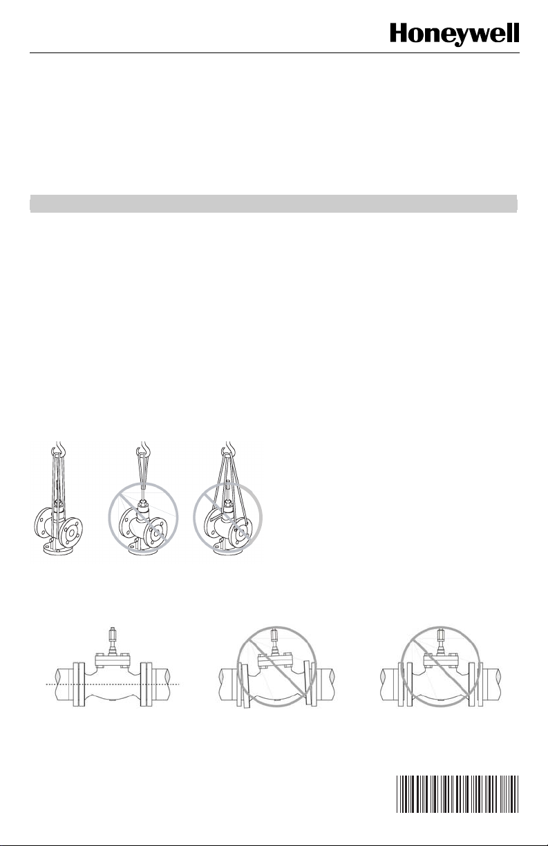
Fig. 1. Proper hoisting of VGF Valves.
Safety
The valves are to be installed by skilled personnel and in
strict accordance with the installation instructions and
local regulations. (See Fig. 1 for proper hoisting method.)
Honeywell assumes no responsibility for damages or
injuries resulting from non-compliance with installation
instructions or standard good practice when mounting,
operating, or maintaining the valves, even if not explicitly
mentioned in the installation instructions. (See Fig. 2 for
basic pipe orientation.) Observe all safety practices when
working with steam systems.
Proper Use
These valves are only for use in cold, warm, hot water
systems and for steam applications. They are designed
for a medium temperature range of from 35 to 355°F, at a
maximum pressure of 125 or 250 psig, depending on
their ANSI body class. They are to be operated with the
appropriate Honeywell actuators only. Please refer to the
VGF family product data sheet, form 63-2618 for detail.
Water should be properly filtered, treated and
conditioned according to local conditions. The installation
of a strainer is strongly recommended.
Fig. 2. Basic pipe orientation.
® U.S. Registered Trademark
Copyright © 2004 Honeywell International Inc. • All Rights Reserved
62-0213

VGF FLANGED GLOBE VALVES
INSTALLATION
When Installing this Product...
1. Read these instructions carefully. Failure to follow
them could damage the product or cause a
hazardous condition.
2. Check ratings given in instructions and on the
product to ensure the product is suitable for your
application.
3. Installer must be a trained, experienced service
technician.
4. After installation is complete, check out product
operation as provided in these instructions.
WARNING
Severe Burn Hazard.
Contact with hot liquid can lead to severe
injury or cause death.
Release system pressure and isolate or drain the
valve pipe section so the medium (steam, water
or glycol solution) does not leak out of the valve
body during installation (see Fig. 3).
CAUTION
Electrical Shock or Equipment Damage Hazard.
Can shock individuals or short equipment
circuitry.
Disconnect power supply to the actuator to
prevent electrical shock and equipment
damage, or remove and cap the air line to the
actuator.
IMPORTANT
• Before installing the valve, raise and lower the
valve stem to make sure that the valve stem
operates freely. Impaired stem operation can
indicate that the stem was bent by rough
handling. This condition can require replacing
the valve.
• Protect the stem from damage due to bending
or scratching.
Location
Select a location where the valve and actuator are
accessible. Allow sufficient space for servicing the valve
and actuator. See Fig. 6 for valve body dimensions.
Mounting the Valve
See Fig. 5 for typical installation.
1. Hoist valve by its body only. Do not lift by stem,
bonnet, flanges, or flange holes. (See Fig. 1.)
2. Install the valve so the flow follows the direction of
the arrow indicated on the valve body.
3. Install the valve so the actuator is above the valve
body. The valve can be installed in any position
between vertical and horizontal. Do not install the
valve with the stem below horizontal or upside
down.
4. When controlling steam, use appropriate high
temperature kit 43196000 and rotate valve body so
that actuator is not positioned directly above the
piping.
5. Use companion flanges with the same number of
bolt holes and dimensions as the valve to be
installed. The optional service flange may be
installed in the lower port. See Table 1 for part
numbers. Use standard cast-iron flanges for the
two end ports.
6. Use a gasket material recommended for the
medium to be handled.
7. Use mounting bolts long enough so the nuts can
use the full length of the nut threads. (See Fig. 4.)
Use bolts 1/8 in. smaller than the diameter of the
bolt hole to allow clearance for installing. (See
Fig. 5.)
Table 1. Service Flange Part Numbers.
Valve Size
in in. (mm) ANSI 125 ANSI 250
2 1/2 (65) 208628 208633
3 (80) 208629 208634
4 (100) 208630 208635
5 (125) 208631 208636
6 (150) 208632 208637
Fig. 3. Piping must prevent leakage.
133 in-lb
(15 Nm)
Fig. 4. Basic proper bolt length.
62-0213 2
 Loading...