

Honeywell VG.025A, VG.015A, VG.020A, VG.040A, VG.032A Product Handbook
...
PRODUCT HANDBOOK
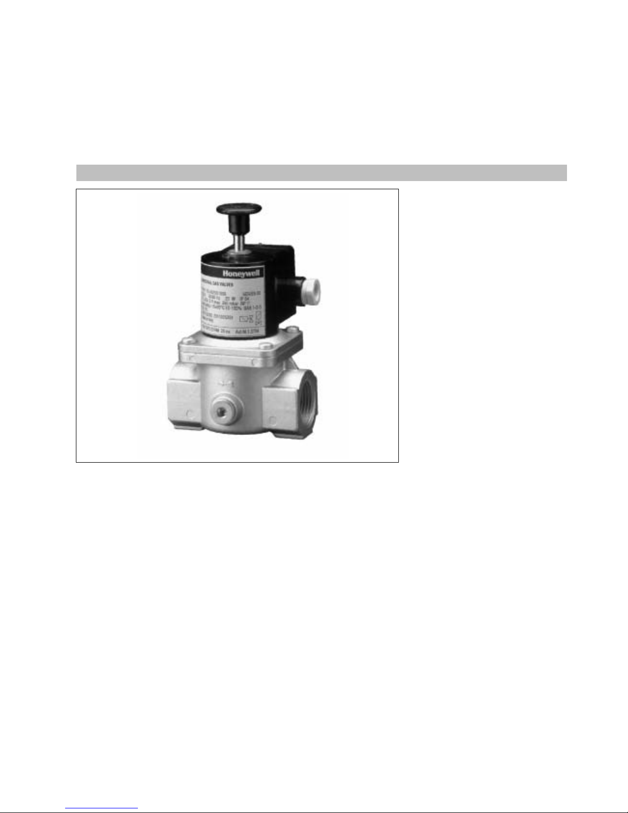
UNIVERSAL GAS VALVES
VG SERIES
SAFETY SOLENOID VALVES
EN2R--9012 9412R0--NE
APPLICATION
Theseseries manually operated
safety solenoid valves are used in
gas leak detection systems.
CONTENTS
General
Description 2
Features 3
Model chart 4
Technical
Specifications 5
Performance characteristics 6
Capacitycurves 7--8
Dimensional drawing 1000 series 9
Dimensional drawing 3000 series 10
Installation and operation
Installation and final checkout 11
Construction and working principles 12
Various
Approvals and standards 13
Ordering information 14
Replacement parts and accessories 15
Subject to change without notice. Printed in the Netherlands.

2
EN2R--9012 9412R0--NE
DESCRIPTION
The VG series safety solenoid valves
offerthe following func tionality:
Normally c losed valve. Manual opening
when energized.
The VG series safety solenoid valves
are suitable forthe control of g aseous
fluids in gas consuming appliances
according to international standards.
The VG series safety solenoid valves
meet the class A specification
according EN161.
The VG series safety solenoid valves
coverawiderangeofpipesize
connections.
From
3
/8” (DN 10) upto and including
3” (DN 80).
The VG series safety solenoid valves
are available withtreaded connection
from
3
/8” (DN 10) upto and including 3”
(DN 80).
The VG series safety solenoid valves
areavailablewith2
1
/2” (DN 65) and
3” (DN 80) flang ed connection.
The VG series safety solenoid valves
have 2 auxiliary pressure stops with
Rp
1
/4” threaded connection b oth at the
inletpressure side of the valve.
The VG series safety solenoid valves
have an inlet sc reen forprotecting the
valve against ingress of dirt.

3
EN2R--9012 9412R0--NE
FEATURES
:
Class ” A” manually operated safety
solenoid valves for use in gas leak
detec tion systems.
:
The VGxxxxAseries safety solenoid
valves have a spring loaded valve
disc which closes when
de--energized.
:
All VGxxxx series safety solenoid
valves have an internal finemesh
screen.
:
Two inlet pressure stops at each side
of the valve.
:
The VGxxxx series safety solenoid
valves have incorporated in the valve
body a wrench boss as well at inlet
as at outlet side.
:
The VGxxxxx series safety solenoid
valves may be assembled on the
pipe line within
p
90 degrees of the
vertical axel.
:
The VGxxxxX3xxx (flanged
connection)series safety solenoid
valves have at inlet sid e two 1” ISO
7--1 connection tap s.
:
The VGxxxx series safety solenoid
valves have electrical connec tion by
terminal block with incorporated
rectifier board.
:
The VGxxxx series safety solenoid
valves have a field replacable
rectifier board.
:
The VGxxxx series safety solenoid
valves have coils turnable over
360
E
.
:
Cable strainrelief can be achieved
by Pg 11 cable gland.
:
The VGxxxx series safety solenoid
cover a wide rang e of pipe sizes
fromDN 10 up to and including
DN 80.
Electrical connection
:
Supply voltage 24, 110, 220 and 240
Volt 50/60 Hz.
:
Enclosureaccording to IP 54.
4
EN2R--9012 9412R0--NE
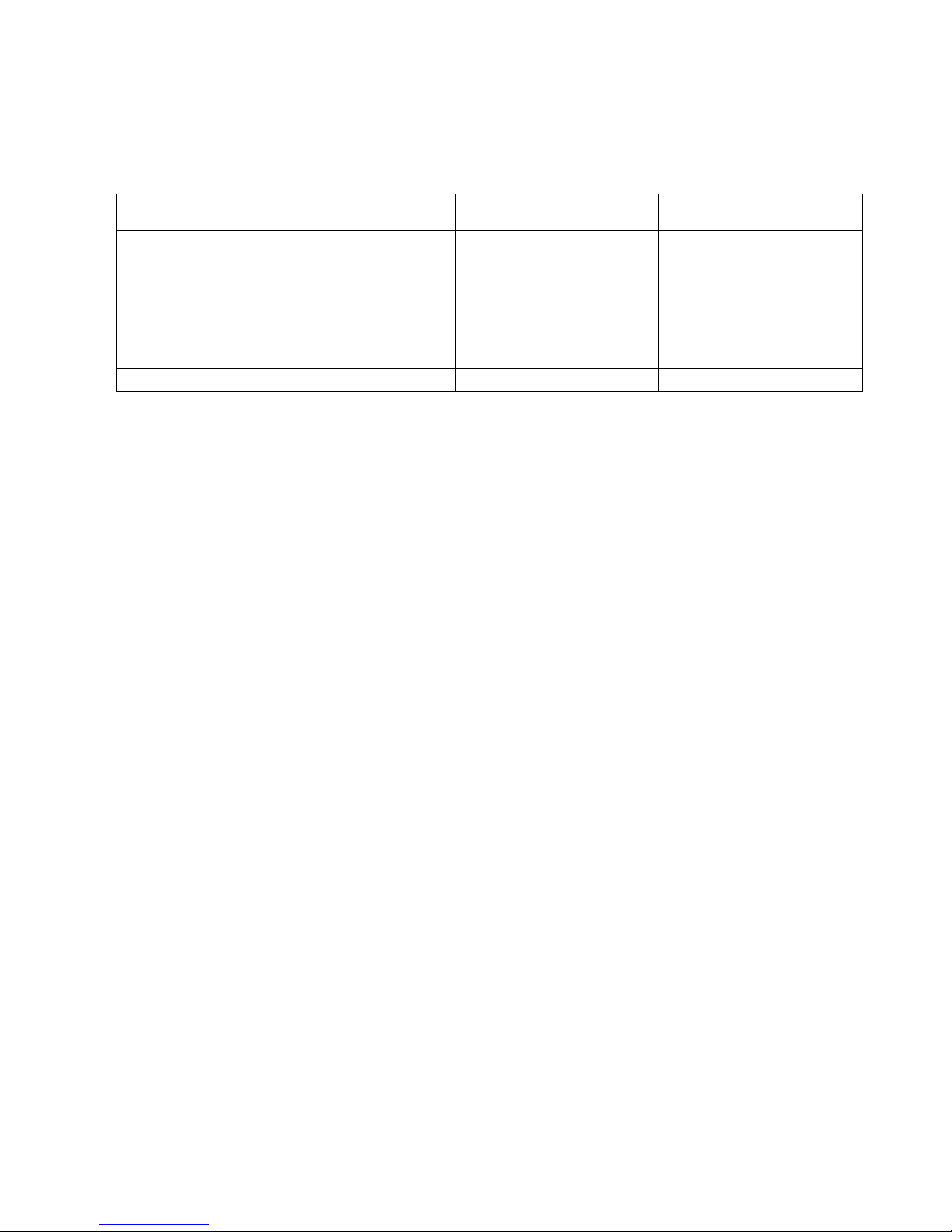
MODEL CHART
Options 1000 series
(internal threaded)
3000 series
(flange connection)
Range: DN 103/8”
DN 15
1
/2”
DN 20
3
/4”
DN 25 1”
DN 32 1
1
/4”
DN 40 1
1
/2”
DN 50 2”
DN 65 2
1
/2”
DN 80 3”
VG.010
VG.015
VG.020
VG.025
VG.032
VG.040
VG.050
VG.065
VG.080
--
--
--
--
--
--
-VGX065
VGX080
Non regulated ON/OFF(VGxXXXA XXXX) Standard Standard
5
EN2R--9012 9412R0--NE
SPECIFICATIONS
Models
The VG series consists of a series
manually operated safety solenoid
valves from
3
/8” upto and including 3”
connection.
VG series solenoid valves
VG.010A (DN 10)
VG.015A (DN 15)
VG.020A (DN 20)
VG.025A (DN 25)
VG.032A (DN 32)
VG.040A (DN 40)
VG.050A (DN 50)
VG.065A (DN 65)
VG.080A (DN 80)
Pipe sizes 1000 series
Inlet and outlet
3
/8” up to and inc luding
3” internalparallel pipe thread
according to
ISO 7--1
Pipe sizes 3000 series
Flanged connection 2
1
/2” and 3”
according to PN 16 UNI 2278--67
Torsion and bending stress
Pipe connections meet Group 2
according EN161 requirements.
Ambient temperature
--1 5
E
C ... 60EC
Supply voltage
24 V, 50/60 Hz
110 V, 50/60 Hz
220 V, 50/60 Hz
240 V, 50/60 Hz
The applicable voltage is led to the
solenoid coil via a rectified circuit.
Dimensions
1000 series: See pag e 9
3000 series: See pag e 10
Electrical connection
Wiring on terminalblock on box.
Cable entry Pg 11.
Coil insulation safety solenoid
valves
Insulation material according class F
Enclosure
IP 54
IP 65 on request
Capacity
See page 7 and 8
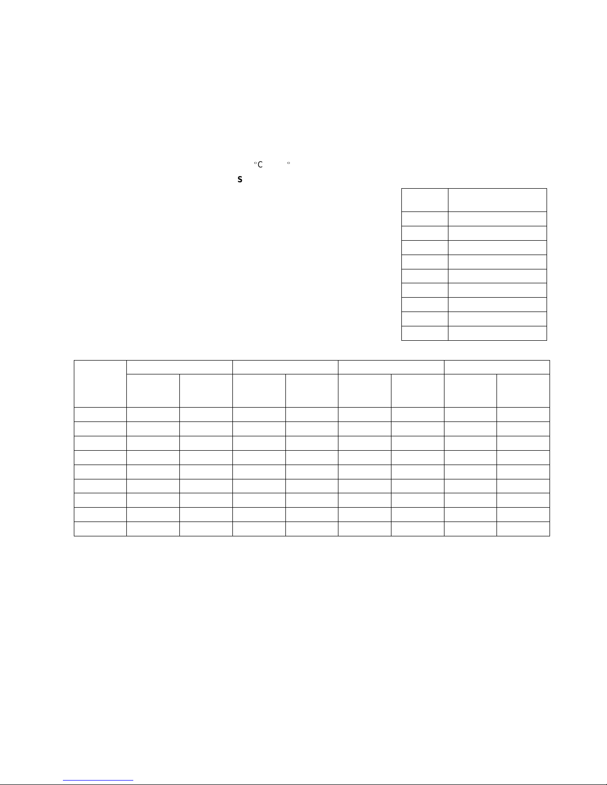
Maximum operating pressure
Model
Maximum operating
pressure (mbar)
VG.010 500
VG.015 500
VG.020 500
VG.025 500
VG.032 500
VG.040 500
VG.050 500
VG.065 350
VG.080 350
Power Consumption (W)
24 V, 50/60 Hz 110 V,50/60 Hz 220 V, 50/60 Hz 240 V,50/60 Hz
Model
number
At nominal
voltage
At 110% of
nominal
voltage
At nominal
voltage
At 110% of
nominal
voltage
At nominal
voltage
At 110% of
nominal
voltage
At nominal
voltage
At 110% of
nominal
voltage
VG.010 4 5 4 6 4,3 5 3 4
VG.015 4 5 4 6 4,3 5 3 4
VG .020 4 5 4 6 4,3 5 3 4
VG.025 4 5 4 6 4,3 5 3 4
VG.032 4 5 4 6 4,3 5 3 4
VG.040 4 5 4 6 4,3 5 3 4
VG.050 12,5 15 13 16 15,3 16 15 18
VG.065 12,5 15 13 16 15,3 16 15 18
VG.080 12,5 15 13 16 15,3 16 15 18
 Loading...