

Page 1
PRODUCT HANDBOOK
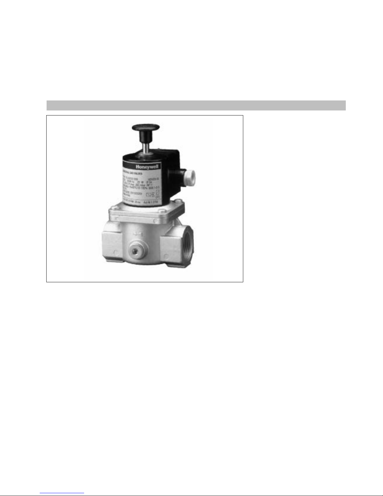
UNIVERSAL GAS VALVES
VG SERIES
SAFETY SOLENOID VALVES
EN2R--9012 9412R0--NE
APPLICATION
Theseseries manually operated
safety solenoid valves are used in
gas leak detection systems.
CONTENTS
General
Description 2
Features 3
Model chart 4
Technical
Specifications 5
Performance characteristics 6
Capacitycurves 7--8
Dimensional drawing 1000 series 9
Dimensional drawing 3000 series 10
Installation and operation
Installation and final checkout 11
Construction and working principles 12
Various
Approvals and standards 13
Ordering information 14
Replacement parts and accessories 15
Subject to change without notice. Printed in the Netherlands.
Page 2

2
EN2R--9012 9412R0--NE
DESCRIPTION
The VG series safety solenoid valves
offerthe following func tionality:
Normally c losed valve. Manual opening
when energized.
The VG series safety solenoid valves
are suitable forthe control of g aseous
fluids in gas consuming appliances
according to international standards.
The VG series safety solenoid valves
meet the class A specification
according EN161.
The VG series safety solenoid valves
coverawiderangeofpipesize
connections.
From
3
/8” (DN 10) upto and including
3” (DN 80).
The VG series safety solenoid valves
are available withtreaded connection
from
3
/8” (DN 10) upto and including 3”
(DN 80).
The VG series safety solenoid valves
areavailablewith2
1
/2” (DN 65) and
3” (DN 80) flang ed connection.
The VG series safety solenoid valves
have 2 auxiliary pressure stops with
Rp
1
/4” threaded connection b oth at the
inletpressure side of the valve.
The VG series safety solenoid valves
have an inlet sc reen forprotecting the
valve against ingress of dirt.
Page 3

3
EN2R--9012 9412R0--NE
FEATURES
:
Class ” A” manually operated safety
solenoid valves for use in gas leak
detec tion systems.
:
The VGxxxxAseries safety solenoid
valves have a spring loaded valve
disc which closes when
de--energized.
:
All VGxxxx series safety solenoid
valves have an internal finemesh
screen.
:
Two inlet pressure stops at each side
of the valve.
:
The VGxxxx series safety solenoid
valves have incorporated in the valve
body a wrench boss as well at inlet
as at outlet side.
:
The VGxxxxx series safety solenoid
valves may be assembled on the
pipe line within
p
90 degrees of the
vertical axel.
:
The VGxxxxX3xxx (flanged
connection)series safety solenoid
valves have at inlet sid e two 1” ISO
7--1 connection tap s.
:
The VGxxxx series safety solenoid
valves have electrical connec tion by
terminal block with incorporated
rectifier board.
:
The VGxxxx series safety solenoid
valves have a field replacable
rectifier board.
:
The VGxxxx series safety solenoid
valves have coils turnable over
360
E
.
:
Cable strainrelief can be achieved
by Pg 11 cable gland.
:
The VGxxxx series safety solenoid
cover a wide rang e of pipe sizes
fromDN 10 up to and including
DN 80.
Electrical connection
:
Supply voltage 24, 110, 220 and 240
Volt 50/60 Hz.
:
Enclosureaccording to IP 54.
Page 4
4
EN2R--9012 9412R0--NE
MODEL CHART
Options 1000 series
(internal threaded)
3000 series
(flange connection)
Range: DN 103/8”
DN 15
1
/2”
DN 20
3
/4”
DN 25 1”
DN 32 1
1
/4”
DN 40 1
1
/2”
DN 50 2”
DN 65 2
1
/2”
DN 80 3”
VG.010
VG.015
VG.020
VG.025
VG.032
VG.040
VG.050
VG.065
VG.080
--
--
--
--
--
--
-VGX065
VGX080
Non regulated ON/OFF(VGxXXXA XXXX) Standard Standard
Page 5
5
EN2R--9012 9412R0--NE
SPECIFICATIONS
Models
The VG series consists of a series
manually operated safety solenoid
valves from
3
/8” upto and including 3”
connection.
VG series solenoid valves
VG.010A (DN 10)
VG.015A (DN 15)
VG.020A (DN 20)
VG.025A (DN 25)
VG.032A (DN 32)
VG.040A (DN 40)
VG.050A (DN 50)
VG.065A (DN 65)
VG.080A (DN 80)
Pipe sizes 1000 series
Inlet and outlet
3
/8” up to and inc luding
3” internalparallel pipe thread
according to
ISO 7--1
Pipe sizes 3000 series
Flanged connection 2
1
/2” and 3”
according to PN 16 UNI 2278--67
Torsion and bending stress
Pipe connections meet Group 2
according EN161 requirements.
Ambient temperature
--1 5
E
C ... 60EC
Supply voltage
24 V, 50/60 Hz
110 V, 50/60 Hz
220 V, 50/60 Hz
240 V, 50/60 Hz
The applicable voltage is led to the
solenoid coil via a rectified circuit.
Dimensions
1000 series: See pag e 9
3000 series: See pag e 10
Electrical connection
Wiring on terminalblock on box.
Cable entry Pg 11.
Coil insulation safety solenoid
valves
Insulation material according class F
Enclosure
IP 54
IP 65 on request
Capacity
See page 7 and 8
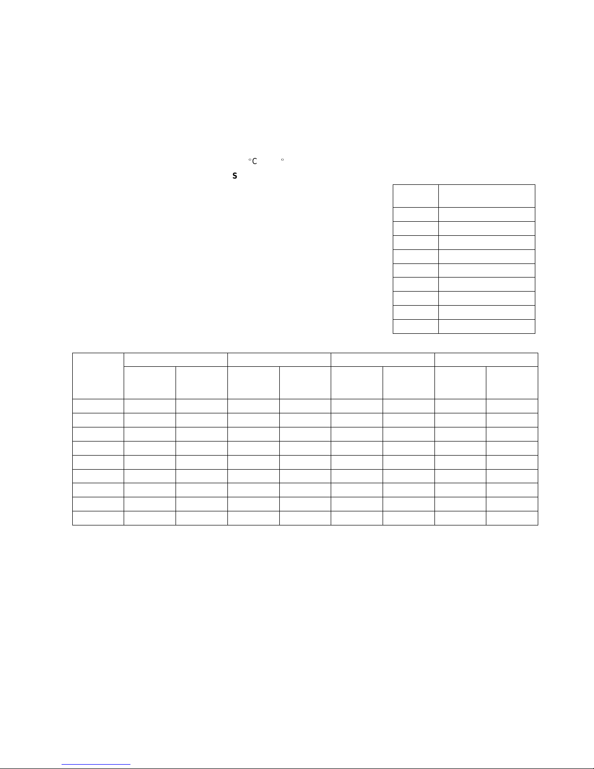
Maximum operating pressure
Model
Maximum operating
pressure (mbar)
VG.010 500
VG.015 500
VG.020 500
VG.025 500
VG.032 500
VG.040 500
VG.050 500
VG.065 350
VG.080 350
Power Consumption (W)
24 V, 50/60 Hz 110 V,50/60 Hz 220 V, 50/60 Hz 240 V,50/60 Hz
Model
number
At nominal
voltage
At 110% of
nominal
voltage
At nominal
voltage
At 110% of
nominal
voltage
At nominal
voltage
At 110% of
nominal
voltage
At nominal
voltage
At 110% of
nominal
voltage
VG.010 4 5 4 6 4,3 5 3 4
VG.015 4 5 4 6 4,3 5 3 4
VG .020 4 5 4 6 4,3 5 3 4
VG.025 4 5 4 6 4,3 5 3 4
VG.032 4 5 4 6 4,3 5 3 4
VG.040 4 5 4 6 4,3 5 3 4
VG.050 12,5 15 13 16 15,3 16 15 18
VG.065 12,5 15 13 16 15,3 16 15 18
VG.080 12,5 15 13 16 15,3 16 15 18
Page 6

6
EN2R--9012 9412R0--NE
PERFORMANCE CHARACTERISTICS
Maximum allowable leakage
Model
Test pressure 1
Test pressure 2
Maximum allowable leakage rate (cm3/h)
(mbar) (mbar)
Internal External
VG.010 6 750 40 40
VG.015 6 750 40 40
VG.020 6 750 40 40
VG.025 6 750 60 60
VG.032 6 750 60 60
VG.040 6 750 60 60
VG.050 6 750 60 60
VG.065 6 525 60 60
VG.080 6 525 60 60
Opening time
Valves are manuallyopened
Closing time
Less than 1 second
Duty cycle
Coil suitable forpermanent
energization
Operationalvoltage range
The safety solenoid valve will funtion
satisfactory between 85% and 110% of
the rated voltage.
Rated voltage:
24 V, 50/60 Hz
110 V, 50/60 Hz
220 V, 50/60 Hz
240 V, 50/60 Hz
Design life
5.000 cycles
Page 7

7
EN2R--9012 9412R0--NE
CAPACITY CURVE DN10, DN15,DN 20,DN 25,DN 32 AND DN 40(THREADED
CONNECTION)
Capacity in m3/hair atap=2,5mbar
3
/8”DN10
1
/2”DN15
3
/4”DN20 1” DN 25 11/4”DN32 11/2”DN40
5 6,4 14,8 16,7 38,5 47,1
2
3
6
4
5
8
10
20
30
60
40
50
1
0,2
0,3
0,6
0,4
0,5
0,8
1
2
3
6
4
5
0,1
a
p(kPa)ap (mbar)
Vn(m3/h)
DN 25
DN 20
DN 32
DN 40
DN 15
DN 10
1 2 3 4 5 6 8 10 20 30 40 50 60 80 100 200 300
Air dv=1
Natural gas (G 25)
d
v
=0,612
Manufactured gas (G 110/120)
d
v
=0,45
Propane (G 31)
d
v
=1,562
Butane (G 30)
d
v
=2,09
0,8
2 3 4 5 6 8 10 20 30 40 50 60 80 100 200
2 3 4 5 6 8 10 20 30 40 50 60 80 100 200
1 2 3 4 5 6 8 10 20 30 40 50 60 80 100 200
1 2 3 4 5 6 8 10 20 30 40 50 60 80 100 200
0,8
300
300 400
Page 8

8
EN2R--9012 9412R0--NE
CAPACITY CURVE DN 50, DN 65, AND 80(TREADED ANDFLANGED
CONNECTION)
Capacity in m3/hair atap=2,5mbar
2”DN50
21/2”DN65 3” DN 80
66,7 94,2 131
2
3
6
4
5
8
10
20
30
60
40
50
1
0,2
0,3
0,6
0,4
0,5
0,8
1
2
3
6
4
5
0,1
a
p(kPa)ap (mbar)
Vn(m3/h)
10 20 30 40 50 60 80 100 200 300 400 500600 800 1000 2000 3000
Air dv=1
8
DN 65
DN 50
20 30 40 50 60 80 100 200 300 400 500600 800 1000 2000
20 30 40 50 60 80 100 200 300 400 500600 800 1000 2000
10 20 30 40 50 60 80 100 200 300 400 500600 800 1000 2000
10 20 30 40 50 60 80 100 200 300 400 500600 800 1000 2000
0,8
3000
3000 4000
DN 80
Natural gas (G 25)
d
v
=0,612
Manufactured gas (G 110/120)
d
v
=0,45
Propane (G 31)
d
v
=1,562
Butane (G 30)
d
v
=2,09
Page 9

9
EN2R--9012 9412R0--NE
DIMENSIONALDRAWING 1000 SERIES
Model Connec tion
Dimensions (mm)
Weight
A B C D
(kg)
VG.010 R
p
3
/8” 72 150 52 85 0,85
VG.015 R
p
1
/2” 72 150 52 85 0,85
VG.020 R
p
3
/4” 86 160 70 85 1
VG.025 Rp1” 150 160 75 85 1
VG.032 Rp11/4” 150 220 110 85 2
VG.040 Rp11/2” 150 220 110 85 2
VG.050 Rp2” 170 285 135 85 4,2
VG.065 Rp21/2” 225 330 170 120 7,5
VG.080 Rp3” 225 330 170 120 7,5
Page 10

10
EN2R--9012 9412R0--NE
DIMENSIONALDRAWING 3000 SERIES
Model Flanged
Dimensions (mm)
Weight (kg )
connection
A B C D
VG.065 21/2” 310 360 120 95 11
VG.080 3” 310 360 120 95 11,3
Page 11

EN2R--9012 9412R0--NE
11
INSTALLATION ANDFINAL CHECKOUT
Warning
:
Take c are thatinstaller is a trained
experienced service man.
:
Turn off gas supply before starting
installation.
:
Disconnect p ower supply to
prevent elec trical shock and/or
equip ment d amage.
Mounting position
The gas valve can be mounted plus or
minus 90 degrees fromthe vertical.
Mounting location
The distanc e between the gas valve
and the wall/ground, must be at least
30 cm.
Main gas connection threaded
valves
:
Take c are that dirt cannot enter the
gas valve during handling.
:
Ensure the g as flows in the same
direction as the arrow on the housing
of the gas valve.
:
Use a sound taper fitting with thread
according to ISO 7--1(BS21, DIN
2999) or a piece of new, properly
reamed pipe, free fromswarf.
:
Do not thread or tighten the pip e or
pipe fitting too far. Otherwise valve
distortion and malfunction could
result.
:
Apply a moderate amount of good
quality thread compound to the pipe
or fitting only, leaving the two end
threads bare.PTFEtape may be
used as an alternative.
:
Inordertotightenthepipeinthe
valve, d o not use the actuator as a
lever b ut use a suitable wrench
operating on the wrench bosses.
Main gas connection flanged valves
:
Take c are that dirt cannot enter the
gas valve during handling.
:
Ensure the g as flows in the same
direction as the arrow on the housing
of the gas valve.
:
Ensure thatinlet and outlet flanges
are in line and separated fromeach
other enoug h to allow the valve to be
mounted between them without
damaging the gasket.
:
Place gasket. If nec essar y grease it
slightly to keep it in place.
:
Mount gas valve between flanges
using the b olts for each flange.
Warning
Tightness test after installation
:
Paintall pipe connections and
gaskets with a strong soap and
water solution.
:
Start the appliance and check for
bubbles. If a leak is found in a p ipe
connection, remake the joint.
A gasket leak can usually be
stopp ed by tightening the mounting
screws. Otherwise, replac e the gas
valve.
Electrical connection
Caution
:
Switc h off p ower supply before
making electrical connections.
:
Take c are that wiring is in
accordance with local regulations.
Use lead wire which can withstand
105
E
C ambient.
The electric on/off operator is provided
with a terminalbloc k for elec trical
connections.
Wiring
Follow the instructions supplied by the
appliance manufacturer.
Final checkout
Setappliance in operation and observe
several complete c ycles to ensure that
components function correctly
Page 12

EN2R--9012 9412R0--NE
12
CONSTRUCTION AND WORKING PRINCIPLES
The VG series safety solenoid valves
are class A fail safe shutt--off valves.
The valve can be opened manually
afterenergizing the operator.
The operator consists of a coil and c oil
housing. Through this op erator moves
a shaft which is connected to the
closing member.On this shafta disc is
mounted which can be moved towards
the coil by pulling the setting knob and
will be kept in that position when the
operator is energized.
De--energizationwill cause the spring
loaded closing member to close.
A strainer made out of steel according
to AISI 303 is incorp orated in the valve.
Valve closing spring is mad e out of
steel ac cording to AISI 302.
Sealsand gaskets aremanufactured
out of hydrocarbon NBR resistantare
according to DIN 3535 and EN 291.
Setting knob
Coil
Gas flow direction
Valvehousing
Printed circuit
Shaft
Spring
Strainer
Shutter
Page 13

EN2R--9012 9412R0--NE
13
STANDARDS ANDAPPROVALS
Standards
The VG series safety solenoid valves
have been designed to meet the
Europ ean Standard EN 161.
The safety solenoid valve meets class
A requirements.
According to bending stress the safety
solenoid valve meets the highest
requirements.
Regarding electric safety, the VG series
safety solenoid valves can be used in
appliances acc ording to European
Standard for a household electrical
requirements EN60335 series and
industrial applications.
The VG series safety solenoid valves
also meet allElectro Magnetic
Compatability standards for
non--industrialand industrial
appliances.
Approvals
The VG series safety solenoid valves
confirm with the following
EC--directives:
:
Gas Appliance Directive
(90/396/EEC)
:
Low Voltage directive (73/23/EEC)
The fact thatthe VG series safety
solenoid valves are certified to
Europ ean Standard EN 161 means that
this series meets morestringent
requirementsthan laid down in the
essential requirementsstated in the
directives and thereforemeets the
requirements in all EC and EFTA
countries.
Details can be found in the approvals
list.
The registrationnumber specific for
each O.S.number is mentioned on the
label of the safety solenoid valve.
Page 14

EN2R--9012 9412R0--NE
14
ORDERING INFORMATION
When ordering specify:
:
Model number of VG series safety
solenoid valve required: see model
number chart below.
:
Order numbers of rep lacement p ar ts
and accessories required, i.e.
flanges, compression fittings: see
replacement parts/acc essoiries.
Note
Most mod els of valves, replacement
parts and accessories will be
available under ” TRADELINE” label.
Ask your wholesaler for details.
VG: Class ”A” manually operated safety
solenoid valve
VG
A: ON/OFF, normally closed
4: Linevoltage
8: Lowvoltage
401
A
odel number chart
9999
Valve size
010: DN 10
015: DN 15
020: DN 20
025: DN 25
032: DN 32
040: DN 40
050 DN 50
065: DN 65
080: DN 80
100: DN 100
Specification number
0
Ordering Specification number
1: Female threaded connection
3: Flange connection
Page 15

EN2R--9012 9412R0--NE
15
REPLACEMENT PARTSAND ACCESSORIES
Warning
Take c are that only qualified persons carry out the installation of p ar ts, accessories, and ad d on c omponents.
Follow the installation instructions included in the package.
Check that the selected part, accessor y or add on component is the correct one for the application in question.
Specifation of data is given in the instructionleafletin the pac kage.
Replace the old gaskets with the new ones supp lied in the p ackage and c heck forleakage when the supp ly is switc hed on
again.
Afterinstallation and/or replacement has been completed, a gas leak test mustbe carried out.
Also check the gas valve for satisfactory operation after fitting accessories
Coils
Descrip tion Order number Packing quantity
Coil for VG .010/.015/.020/.025/.032/.040A:
24 V, 50/60 Hz
110 V, 50/60 Hz
220 V, 50/60 Hz
240 V, 50/60 Hz
BB 020030
BB 020033
BB 020005
BB 020054
1
1
1
1
Coil for VG .050/.065/.080A:
24 V, 50/60 Hz
110 V, 50/60 Hz
220 V, 50/60 Hz
240 V, 50/60 Hz
BB 020027
BB 020031
BB 020006
BB 020055
1
1
1
1
Rectifier boards
Rectifierboard for 24/110/220/240 V, 50/60 Hz
model:
VE.010/.015/.020A
VE.032/.040/.050
VE.065/.080/4100
CS020065 10
Page 16

EN2R--9012 9412R0--NE
16
REPLACEMENT OFCOIL
:
Removesetting knob (1)
:
Unscrew cap (2)withsuitable
wrench and remove it from the coil
assy
:
Removecap of connection box
:
Disconnect c oil fromrectifier board
by releasing both wires from
connector (5)
:
Removecoil from exteria pipe (4)
:
Place new coil in exteria pipe (4)
:
Connect both wires to connector on
rectifier board (5)
:
Replace cap of connection box
:
Replace cap (2)
:
Replace setting knob (1)
REPLACEMENT OFRECTIFIER BOARD
:
Removecap of connection box.
:
Disconnect all electrical c onnections.
:
Remove selflocking nut in the center
of the board.
:
Removethe rectifier board
:
Place new board into the box
:
Replace selflocking nut
:
Reconnect all electrical connections
:
Replace cap of connection box
 Loading...