

Page 1
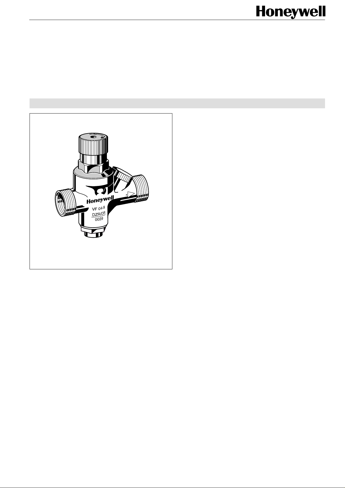
VF 04
Filling valve
for closed heating systems
Product specification sheet
Application
The VF 04 filling valve permit simple and safe filling or refilling of a
closed heating system.
A pressure reducing valve, a check valve and a shutoff facility
are combined in one unit. The pressure gauge connection
enables fitting of a pressure gauge (available as an accessory)
to provide accurate checking of the pressure of a system after
filling.
Special Features
● Housing with internal and external threads
● Outlet pressure adjustable with green adjustment knob
● Green adjustment knob can also be used for shutoff facility
● Simple construction
● The adjustment spring is not in contact with the water
● DIN/DVGW approved check valve
● Balanced-seat pressure reducing valve - inlet pressure
fluctuations do not influence outlet pressure
● Integral shutoff facility
● Alternative connections
Construction
The filling valve comprises:
● Housing with G
● Spring bonnet with adjustment opening
● Green adjustment knob
● Pressure reducing valve
● Non return valve cartridge
● Shutoff insert
Materials
● Brass housing, dezincification resistant
● High-quality synthetic material spring bonnet
● Spring steel adjustment spring
● High-quality synthetic material non return valve cartridge
● Fibre-reinforced NBR diaphragm
● NBR seals
1
/4" pressure gauge connection
Range of Application
Closed heating systems to DIN 4751
Technical Data
Operating temperature Maximum 70 °C
Inlet pressure Maximum 16.0 bar
Outlet pressure 1.5 bar to 6.0 bar adjustable
Connections R
1
/2" internal and R 3/4" external threads
Subject to change EN0H-1022GE23 R1100
1
Page 2
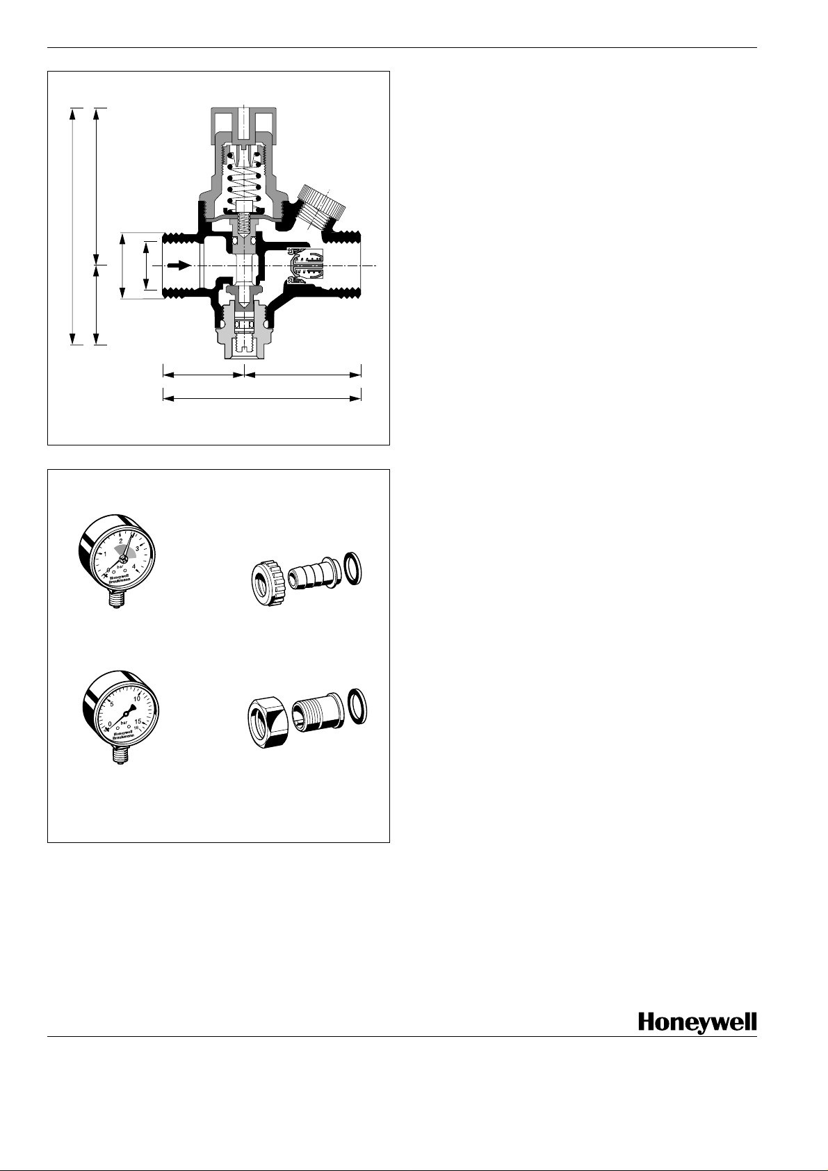
D 04 Filling valve
107.5
/4
3
G
40 67.5
Method of Operation
The integral pressure reducing valve operates by means of a
force equalising system. The force of a diaphragm operates
against the force of an adjustment spring. The inlet pressure
does not influence either opening or closing of the valve. Inlet
pressure fluctuations do not therefore influence the outlet
pressure, thus providing inlet pressure compensation. An
integral check valve protects the drinking water supply by
allowing water to pass through in only one direction. In the flow
direction, a seal disc is pushed open against the force of a
/2
1
G
spring by differential pressure.
Versions
1
VF 04 -
/2 E = With internal and external threads
MF 126
M 39 K
34.5
83
48.5
0903454
VST 06 A
Accessories
MF 126 Pressure gauge
Housing diameter 63 mm, connection thread
1
G
/4”, range 0 - 4 bar , with red hand at 1.5 bar,
red mark at 2.5 bar and green field between 1.5
and 2.5 bar
M 39 K Pressure gauge
Housing diameter 63 mm, connection thread
1
G
/4". Range: 0 - 10 bar .
Please indicate upper value of pressure range
when ordering
0903454 Hose connector union complete
With hose connector union, screw and
gasket ring
VST 06-½ A Connection set
With threaded union connector , screw and
gasket ring
Home and Building Control
Honeywell AG
Hardhofweg · D-74821 Mosbach, Germany
Phone (49) 6261 81-0 · Fax (49) 6261 81-309 http://europe.hbc.honeywell.com
Subject to change EN0H-1022GE23 R1100
2
 Loading...