

Page 1
Vertex M Continuous Gas Monitor
Technical Handbook
• Table of Contents
• Introduction
• Installation
• Startup
• Operation
• Maintenance
• Troubleshooting
• Installation Drawings
• Specifications
• Detectable Gases
• Replacement and Consumable
Items
• Optional Relay Specifications
• Network Interface and Options
• 4-20mA Analog Output Option
• Line Integrity Test Option
• Warranty Statement
Page 2
Vertex MTM 24-Point Continuous Monitor
N OT I C E
WARNING
DANGER
!
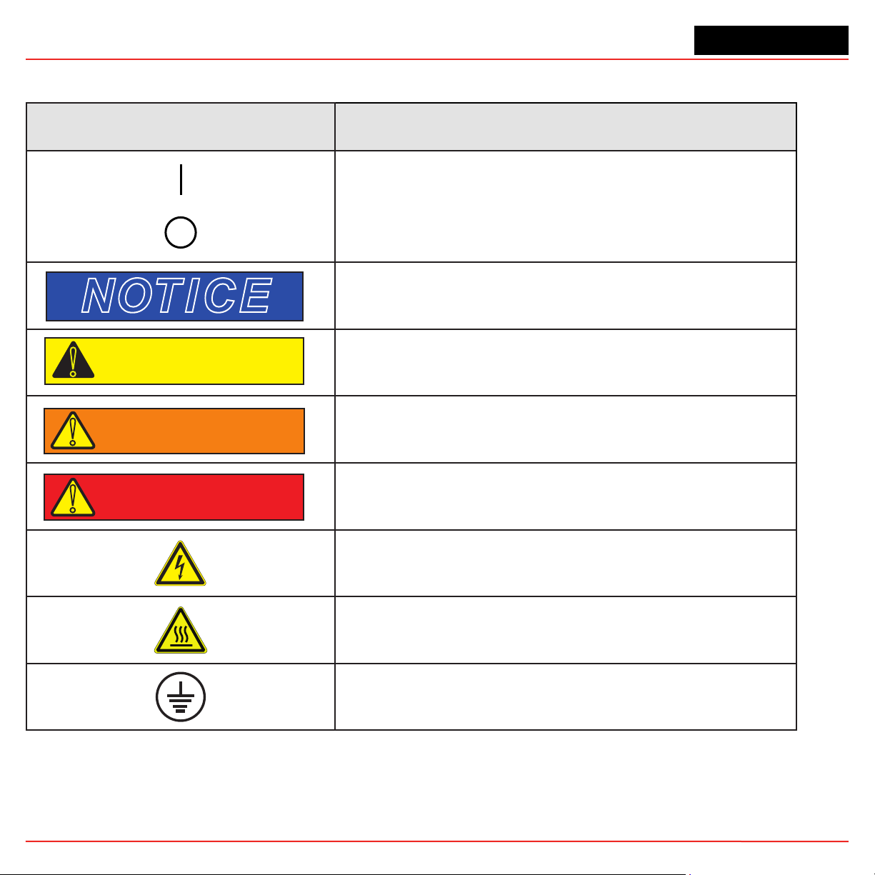
Vertex M Continuous Monitor Symbols
Symbol Description
Power on
Power off
Potential damage to the device or other property, maintenance
procedures, and “refer to manual” instructions.
Lifting instructions, low clearances, slipping/tripping hazards,
!
CAUTION
!
minor corrosive dangers. Also used when defining personal
protective equipment (gloves, dust masks, etc.)
Personal injury risk: machinery hazards around guarded
equipment, moving parts, crush/pinch hazards, flying debris, and
arc flash hazards.
Vertex M TM Technical Handbook
The most dangerous or potentially lethal hazards: unguarded
equipment, confined space entrances, and lockout labels.
Caution: possibility of electric shock
Caution: hot surface
Protective conductor terminal (ground terminal)
i
Page 3
Vertex MTM 24-Point Continuous Monitor
EMC Considerations
Your Honeywell Analytics monitor has been designed
to comply with applicable Electromagnetic Compatibility
(EMC) standards at the time of manufacture. The design
includes filtering, shielding and bypassing techniques.
At the time of certification, simulated customer Input/
Output (I/O) schemes were tested.
All methods used in your equipment for emission
suppression and reduction of susceptibility are
interactive. Modifications to the instrument could result
in increased emissions and higher vulnerability to other
radiated fields.
Following the guidelines in this EMC Considerations
section will ensure your instrument maintains the
highest degree of EMC integrity. The guidelines listed
apply only to I/O emissions and do not apply to A.C.
and D.C. instrument power connections.
Cabling
At a very minimum, all cables should include a braided
shield. Ideal results have been obtained with twisted
pair cabling which has a foil shield surrounding each
pair plus foil and 90% braid shielding around the b undle.
In addition, ensure local electrical code requirements
are met.
The following cable parameters must be considered:
Braid
Foil
Twisted Pair
Stranded Pair
Shield
Termination
Must have a minimum 90% coverage
When used with braid, provides 100% coverage
Do not use foil alone. It has a tendency to break.
Provides for cancelling of magnetic fields
Provides the greatest surface area
Continuation of the shield to the cabinet earth
ground is most important. For discrete wire
terminations, pigtails to the cabinet (connector)
ground should be extremely short (absolutely no
greater than three inches). For multiconductor
connector terminations, only 360° shielded
shells should be used.
Vertex M TM Technical Handbook
Note:
Honeywell Analytics product testing uses >90% braid
with foil (around the bundle); twisted pair; stranded 24
AWG (minimum wiring for all qualification and certification testing.)
Connectors
All qualification and certification of Honeywell Analytics
products were achieved with high quality connectors,
providing 360° shield coverage. These connectors
generally had metal shells.
Failure to properly secure the connector to the
equipment will result in high emission levels. Also,
poorly constructed or improperly assembled connectors
can be a high source of radiated noise and provide a
path for external signals into the monitor.
ii
Page 4
Vertex MTM 24-Point Continuous Monitor
Table of Contents
Symbols Used on Your Instrument ..................................i
EMC Considerations
Cabling
Connectors
..........................................................................ii
....................................................................ii
.......................................................i
Introduction ................................................... 1-1
System Overview ........................................................1-2
Manufacturer
General Safety
System Components
Vertex M Front
Vertex M Back
Sample Tubing, Exhaust and Wiring Ports
Analyzer Side Panel
Analyzer Front
System Controls
Data Acquisition Computer (rear)
Back of Chemcassette
Main PLC
4-20mA Analog Output Option PLC
Menu Map
Analyzer Modules
Sampling System
Chemcassette
Detector Optics
Stain Pattern
Chemcassette
Optional ChemCam
Sample Filters
Pyrolyzer Module Detection System
Pyrolyzer Fan
Vacuum Pumps
Multiple Gas Monitoring
Control System
Data Acquisition Computer
Programmable Logic Controller
............................................................1-2
.........................................................1-2
..................................................1-2
.........................................................1-3
..........................................................1-4
...............1-5
................................................1-6
.........................................................1-7
......................................................1-7
............................1-8
®
Module ..............................1-9
...............................................................1-10
......................1-11
.................................................................1-12
.....................................................1-13
......................................................1-13
®
Detection System ............................1-14
......................................................1-14
..........................................................1-14
®
Tapes ............................................1-15
...............................................1-15
........................................................1-15
.........................1-16
.........................................................1-16
........................................................1-16
............................................1-16
.........................................................1-17
....................................1-17
.............................1-17
Installation ..................................................... 2-1
Introduction .................................................................2-2
Surveying the Installation Site
Placement of the Vertex M System
Exposure to Dust and Humidity
Sample Transport Time
Instrument Dimensions
Sample Locations
Sample Line Particulate Filter Use
Optional Floor Mounting
Installing Sample Lines/Filters
Sample Line Installation Requirements
Sample Line Connections
Installing Sample Line Particulate Filters
Installing Pump Exhaust Line
Exhaust Line Installation Requirements
Exhaust Line Connection
Electrical Power
Connecting AC Power
Power On/Off
Data Acquisition System
Printer
External Network Connection
Network Computer Security
Wiring Alarm Relays
Relay Contacts
Wiring Guidelines
......................................................................2-7
....................................................2-2
..........................................................2-5
...........................................................2-6
...................................................2-8
........................................................2-8
....................................................2-9
....................................2-2
..........................2-2
...............................2-2
............................................2-2
............................................2-2
..........................2-3
.............................................2-3
....................................2-3
...................2-3
........................................2-4
.................2-4
.....................................2-4
..................2-5
.........................................2-5
..............................................2-5
.............................................2-6
..................................2-7
.....................................2-8
Startup ........................................................... 3-1
Startup ........................................................................3-2
Initial Startup............................................................3-2
Factory Configuration
Getting Started
Verify Installation
Power Up
Start Program
...........................................................3-2
........................................................3-2
....................................................................3-2
.............................................................3-4
..............................................3-2
Table of Contents
iii
Page 5
Vertex MTM 24-Point Continuous Monitor
Configuration Utility ....................................................3-6
Define Gas Location
Configure Analyzers and Points
Set Analyzer Window
Configure Point
Define and Assign Relays
Configure PLC
Set Alarm Relays
Set Fault Relays
..............................................3-17
............................3-19
.............................................3-20
......................................................3-21
......................................3-28
.......................................................3-29
...................................................3-30
.....................................................3-32
Profile Management-File Menu..............................3-34
Other Menu
Load Tape
Verify Flow Rates and Supply Vacuum
Verify Flow Rates
Leak Checking Sample Lines
Reconfigure
Moving to a New Site
System Shut Down
............................................................3-34
.................................................................3-34
.....................3-35
...................................................3-35
...................................3-39
..............................................................3-39
................................................3-40
...................................................3-41
Operation ....................................................... 4-1
Introduction .................................................................4-2
Monitoring Mode Overview
Main Screen
...............................................................4-3
System Display Area
Point Detail Display Area
Function Buttons
Project Functions
....................................................4-10
......................................................4-10
Log In and Log Out
Changing Password
Updating Program..................................................4-12
Restore OnScreen Keyboard
Stopping Project
Review Functions
Event History
Data Trend
....................................................4-12
.....................................................4-12
.........................................................4-13
.............................................................4-20
Optional ChemCam
Event List
Menu Buttons
...............................................................4-24
...........................................................4-26
.........................................4-2
...............................................4-4
.........................................4-8
................................................4-11
...............................................4-11
.................................4-12
...............................................4-22
Run Time Options ..................................................4-26
Flow Calibration
Maintenance
Diagnostics
Service
...................................................................4-44
Security Access
Configuration
OnScreen Keyboard
Restore OnScreen Keyboard
....................................................4-32
..........................................................4-40
............................................................4-41
.....................................................4-47
.........................................................4-48
.................................................4-48
.................................4-48
Maintenance .................................................. 5-1
Introduction .................................................................5-2
Maintenance Schedules
Chemcassette
®
Analyzer Maintenance.......................5-3
Remove and Replace Analyzer Particulate Filters
Remove Filters
Replace Filters
.........................................................5-4
.........................................................5-4
Change Chemcassette
Replacing an Analyzer
Disconnecting Cables
Remove Analyzer
Install Analyzers.......................................................5-7
Remove and Replace Pyrolyzer Filters
Remove Filters
Replace Filters
.........................................................5-8
.........................................................5-8
Remove and Install Pumps
Remove Pump
.......................................................5-11
Install New Pump
Remove and Install Power Supplies
Remove Supply
Replace Supply
.....................................................5-12
.....................................................5-12
Clean the Touch Screen
PLC Module Battery Backup Check
File Maintenance
Optics Cleaning
......................................................5-14
........................................................5-15
.............................................5-2
..5-3
®
Tape ..................................5-5
................................................5-6
..............................................5-6
....................................................5-7
......................5-7
.........................................5-9
...................................................5-11
.........................5-12
...........................................5-12
.........................5-13
Table of Contents
iv
Page 6
Vertex MTM 24-Point Continuous Monitor
Troubleshooting ........................................... 6-1
Introduction .................................................................6-2
General System Problems
Maintenance Faults
Instrument Faults
Information Events
LIT-Related Informational Events
Manual Analyzer Override
....................................................6-5
......................................................6-10
....................................................6-16
..........................................6-2
...........................6-19
........................................6-20
Installation Drawings ...................................A-1
Introduction ................................................................A-2
Floor Space Requirements
General Considerations and Cooling
General Wiring
4-Port Manifold Option
Floor Mounting Option
...........................................................A-5
........................................A-3
.........................A-4
...............................................A-7
...............................................A-8
Specifications ...............................................B-1
Introduction ................................................................B-2
Filter Compatibility
Physical Dimensions..................................................B-3
Nominal Transport Times
.....................................................B-2
...........................................B-4
Detectable Gases..........................................C-1
Detectable Gases ......................................................C-2
Replacement and Consumable Items .........D-1
Consumables .............................................................D-2
Chemcassettes
End of Line Particulate Sample Filters
Analyzer Filters
Pyrolyzer Filters
Rack Filters
Printed Circuit Boards
Pyrolyzers
All Analyzers
Power Distribution Module
Components
All Analyzers
®
.....................................................D-2
..................D-2
.......................................................D-2
......................................................D-2
.............................................................D-2
................................................D-2
...............................................................D-2
...........................................................D-2
......................................D-2
..............................................................D-2
...........................................................D-2
Pyrolyzers ...............................................................D-3
Rack Systems
Power Distribution Module
Pump Modules
.........................................................D-3
...................................D-3
........................................................D-3
Optional Relay Specifications .....................E-1
Relay Output Contacts...............................................E-2
Relay Contact Ratings
Default Relay Assignments
Introduction
Main PLC
Terminal Assignment of 1746-OW16 Relay Module
Terminal Assignment of 1746-OX8 Relay Module
.............................................................E-3
................................................................E-3
...............................................E-2
........................................E-3
E-3
.E-4
Network Interface and Options ...................F-1
Network Interface and Options ..................................F-2
OLE for Process Control (OPC) Interface
Setting Up an OPC Client Application
Data Values Common to Fieldbus Networks
Alarms and Faults
Concentrations
Heartbeat
Data Map
Profibus Option (P/N 1295-275)
Termination
Profibus Module Configuration
DeviceNet Interface (P/N 1295-0329)
ControlNet Interface ............................................... F-14
DF1 Interface (P/N1295-0343)
Modbus Plus Interface (P/N 1295-0330)
LonWorks Interface (P/N 1295-0329)
Modbus/TCP (P/N1295-0520)
Configuring the IP Address
Ethernet/CIP (P/N1295-0519)
Configuring the IP Address
Vertex M Remote Display Setup
Checking Remote Session Count
Determining the IP Address
.............................................................. F-10
................................................................. F-11
........................................................... F-12
................................................... F-9
....................................................... F-9
.............................. F-12
............................. F-12
................................ F-15
................................. F-17
................................... F-17
................................. F-20
................................... F-21
.............................. F-21
.................................. F-22
.................. F-3
.................... F-3
............. F-9
...................... F-14
................. F-16
...................... F-16
......................... F-21
Table of Contents
v
Page 7
Vertex MTM 24-Point Continuous Monitor
Basic Desktop Station Setup ................................ F-22
Installing Java Runtime Environment Software
Install Adobe Reader Software
Create HMI account
Starting the Niagara Remote Display
Full Desktop Station Setup
Add Honeywell software to Desktop
Create a “Honeywell Analytics” account
Create Group “VertexDCOMUsers”
Disable Windows Firewall
Configure DCOM
Windows Firewall
Create matching Windows Accounts
Demonstrating Remote OPC Communication
Setup Procedure
Demonstration with Matrikon OPC Explorer
Demonstration with DAClient
.......................................... F-22
............................................... F-27
............................................... F-32
................................................... F-34
.......................... F-22
................ F-22
................................... F-25
.................. F-25
............ F-25
................... F-25
.................................. F-27
................. F-33
................................ F-38
4-20mA Analog Output Option ....................G-1
Overview ....................................................................G-2
Hardware Requirements
Configuration Requirements
Operational Description
............................................G-2
......................................G-2
.............................................G-3
. F-22
........ F-34
......... F-35
Line Integrity Test Option ............................H-1
Warranty Statement....................................... I-1
Chemcassette® Device Warranty Statement................I-2
Chemcassette
Table of Contents
®
Warranty .............................................I-3
vi
Page 8

Vertex MTM 24-Point Continuous Monitor
1 Introduction
Vertex M TM Technical Handbook
1-1
Page 9

Vertex MTM 24-Point Continuous Monitor
1.1 System Overview
The Honeywell Analytics Vertex M™ System
continuously monitors up to 24 remote locations
for toxic gases. It responds to gases that exceed
programmed levels by:
• Triggering alarms and opening event windows
to warn operators of high or low concentrations
• Triggering relays to external devices
• Displaying the location, gas type and gas
concentration
• Storing the alarm information in a database
The Vertex M System provides fast response to a wide
range of gases. Each location may be up to 400 ft
(122 m) from the Vertex M System. The system uses
one or more of Honeywell Analytics’ Chemcassette®
analyzers, with or without pyrolyzer, to provide a
monitoring system tailored to meet the requirements
of the facility.
The V ertex M System incorporates a range of redundant
and protective features for maximum uptime:
• Filters, Chemcassettes® and major
components in one of the analyzers can
be replaced while the remaining analyzers
continue to function
Operation can be through an LCD touch screen or
through a local area network (LAN).
Chemcassette® is a registered trademark of Honeywell Analytics, Inc.
1.1.1 Manufacturer
The Vertex M System is manufactured by:
Honeywell Analytics Inc.
405 Barclay Boulevard
Lincolnshire, IL 60069 USA
www.honeywellanalytics.com
1.1.2 General Safety
Follow all installation and operational instructions to
ensure the safe and reliable operation of this unit.
If this monitor is used in a manner not specified by
Honeywell Analytics Inc., the protection provided by
the equipment may be impaired.
• Intelligent analyzer modules allow one to stop
monitoring with no effect on the remaining
modules
• Power supplies are redundant
• Pumps are redundant
• The system powers up in the same state as
when powered down
Section 1 - Introduction 1-2
1.2 System Components
The following photos illustrate Vertex M System
components, ports, connections and controls. From
the main front and back photos, click on the labels to
see the detail photos.
Page 10
Vertex MTM 24-Point Continuous Monitor
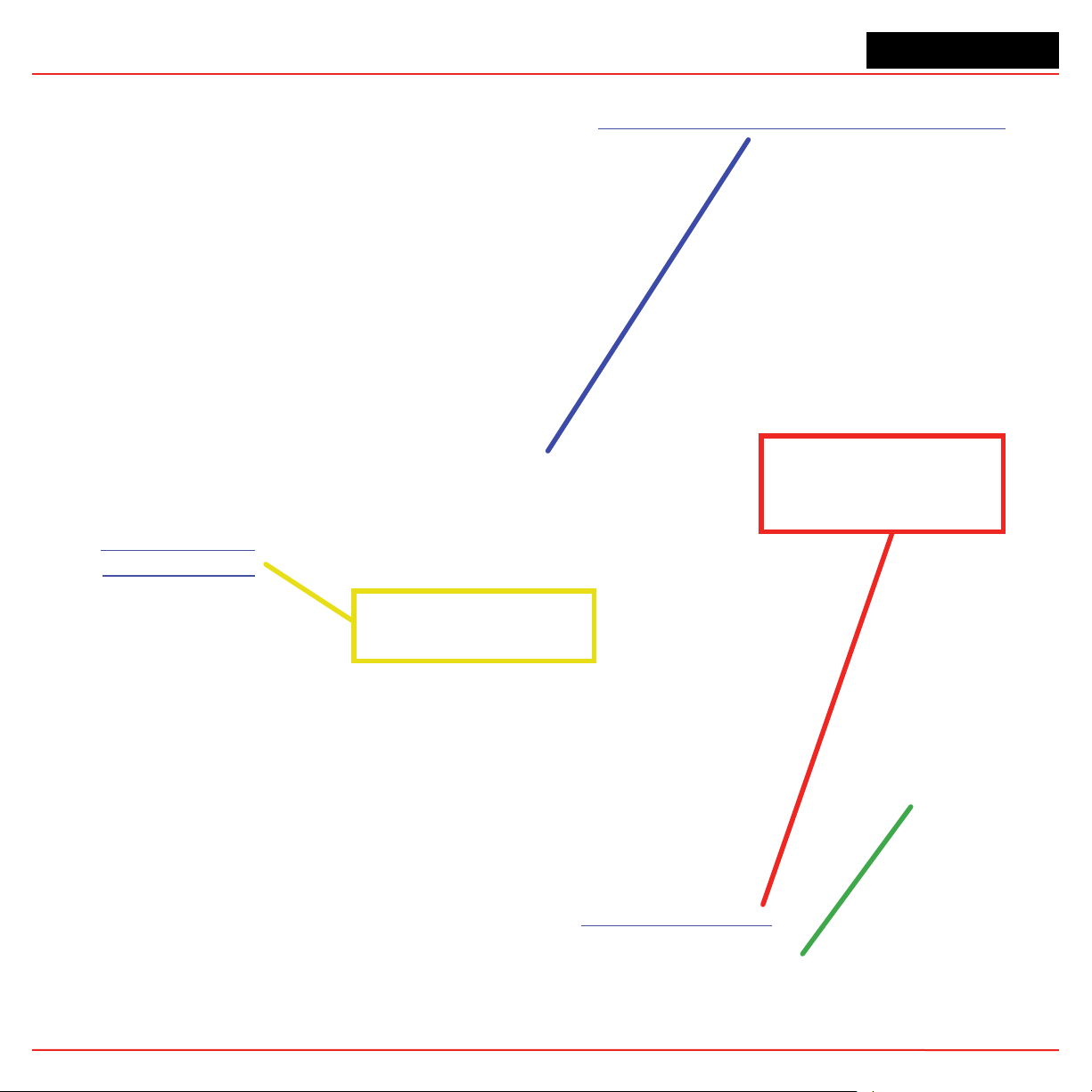
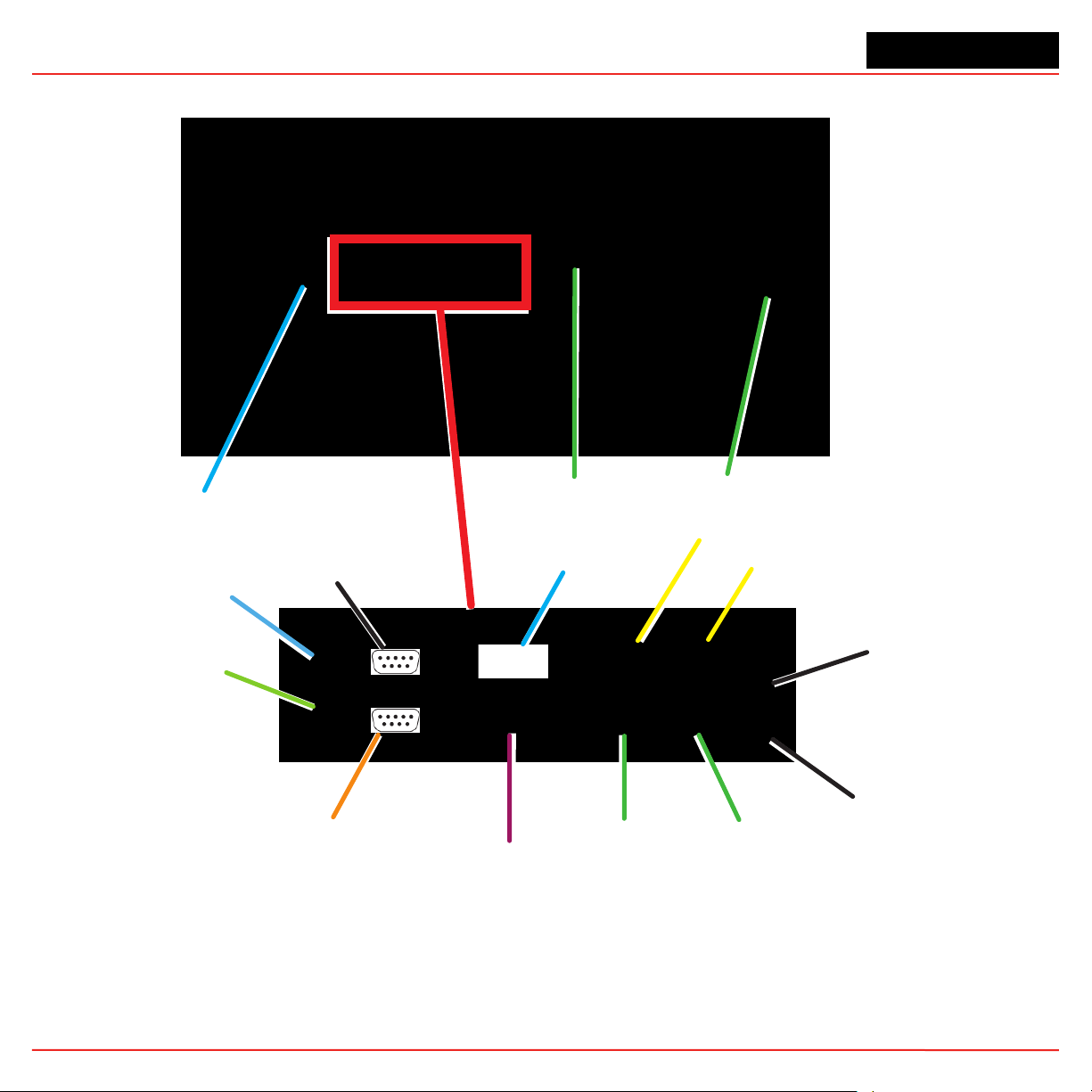
1.2.1 Vertex M Front
Sample Tubing, Exhaust and Wiring Ports
Relay PLC (behind monitor)
See Relay Options or Network Interface Options
Touch Screen
System Controls
Pyrolyzer Analyzer
Analyzer Side Panel
Universal Chemcassette
Analyzer
Analyzer Front
®
Section 1 - Introduction 1-3
Page 11
Vertex MTM 24-Point Continuous Monitor
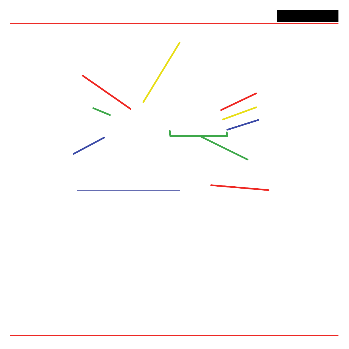
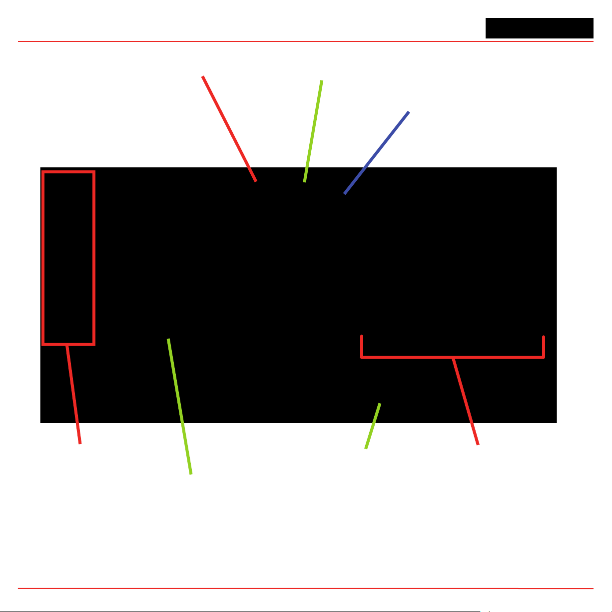
1.2.2 Vertex M Back
Back of Pyrolyzing Chemcassette Analyzer
Data Acquisition
Computer (rear)
Pyrolyzer step-up/Isolation transformer
Section 1 - Introduction 1-4
4-20mA Option PLC
Page 12
Vertex MTM 24-Point Continuous Monitor
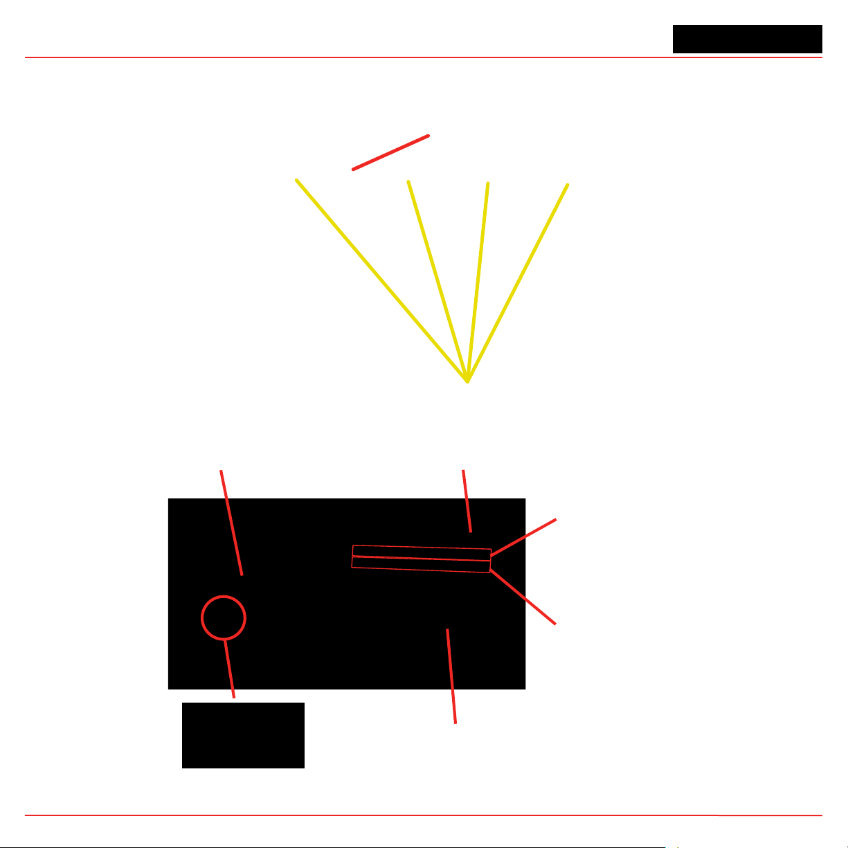
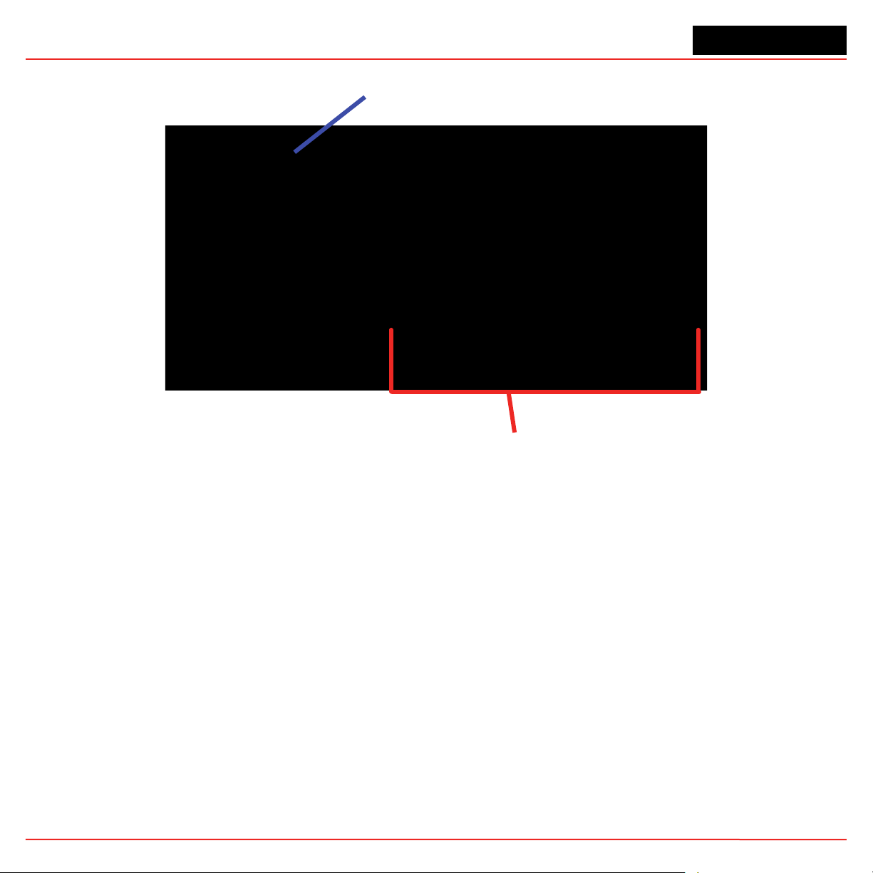
1.2.3 Sample Tubing, Exhaust and Wiring Ports
AC Input
0.75 in pipe thread
System Exhaust
0.5 in (12.7mm) tubing
Analyzer 3 Sample Ports
Alarm Wiring Conduit Plate
2 in (50.8mm)
Power Connection
Access Panel
3-Port Manifold for multiple gas sampling
See Section A.4 Nominal T r ansport Times for tubing
length limitations
Note:
The Alarm wiring conduit plate must remain in place if not used.
Analyzer 2 Sample Ports
Analyzer 1 Sample Ports
Points 1 thru 8 (Left to Right)
Section 1 - Introduction 1-5
Page 13
Vertex MTM 24-Point Continuous Monitor
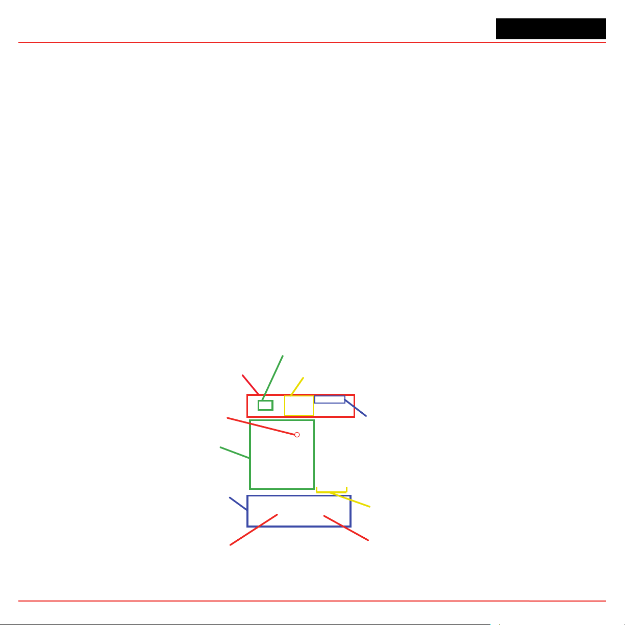
1.2.4 Analyzer Side Panel
Exterior View
Slide Latch
Access Screws
Internal View
Analyzer CPU
ChemCam Option
Proportional Valv e Filters
Section 1 - Introduction 1-6
Sample Pressure
Transducers
Sample Flow
Transducers
Sensor Interface PCB
Page 14
Vertex MTM 24-Point Continuous Monitor
1.2.5 Analyzer Front
1.2.6 System Controls
Rack Power Switch and Circuit Breaker
Power Distribution Module
Analyzer Status LED
Pyrolyzer Analyzer
Data Acquisition
Computer (DAq)
Hot Swap
Hard Drives
Section 1 - Introduction 1-7
24VDC Power Supplies
2
Analyzer DC and Pyrolyzer AC
Power Switches with Indicators
3
Slot
CD-RW Drive
Page 15
Vertex MTM 24-Point Continuous Monitor
1.2.7 Data Acquisition Computer (rear)
Power
Mouse
Keyboard
Serial Com2
(not used)
Serial interface
for touchscreen
(COM 1)
USB (3)
Touchscreen
LCD
video
video
USB,
Chemcam
(3 ports)
USB Host Device
Internal Ethernet
External Ethernet
USB (Com8)
to PLC
(this port only)
Caution:
Restrict access to the USB port to reduce the risk of malicious software being introduced.
Note:
Speakers
(not used)
Microphone
(not used)
This photograph shows a typical port configuration. Port and slot locations vary from model to model.
Section 1 - Introduction 1-8
Page 16

Vertex MTM 24-Point Continuous Monitor
1.2.8 Back of Chemcassette® Module
ChemCam USB Connection
(Optional)
Analyzer Communications
(Ethernet)
Analyzer 24V
Power Supply
Multi-Function
Connector
Note:
Connection secured by slide latch. Push up to open. Push down to close.
Section 1 - Introduction 1-9
Circular Tubing Harness
Cable Carrier
Page 17
Vertex MTM 24-Point Continuous Monitor
1.2.9 Main PLC
PLC Processor
Module
DH485/RS232
Interface Module
Expansion slot for optional
Communications Interface
DH485 Link
Coupler
PLC Power Supply
Section 1 - Introduction 1-10
Advanced Interface
Converter
Optional Relay
Modules
Page 18
Vertex MTM 24-Point Continuous Monitor
1.2.10 4-20mA Analog Output Option PLC
Power Supply
4-20mA Output Modules (6X)
Section 1 - Introduction 1-11
Page 19
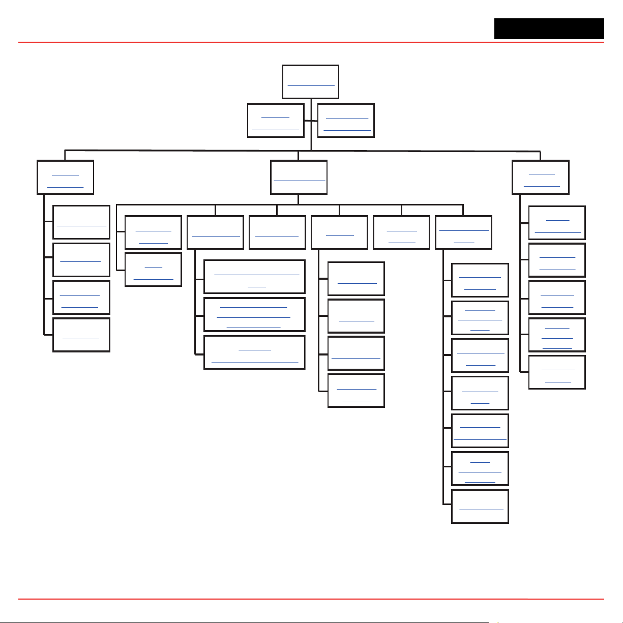
Vertex MTM 24-Point Continuous Monitor
Review
Functions
Event History
Data Trend
ChemCam
(Optional)
Event List
Main Screen
System
Display Area
Point Detail
Display Area
Menu Buttons
Run Time
Options
Flow
Calibration
Maintenance
Analyzer
Operation/Maintenance
Remove and Replace
Chemcassette Analyzer
Particulate Filters
Change Chemcassette
Tape
Diagnostics
Service
Alarm Test
Fault Test
4-20 mA Test
Authorized
Service
Security
Access
Configuration
Utility
Project
Functions
Define Gas
Location
Configure
Analyzers and
Points
Set Analyzer
Window
Configure
Point
Define and
Assign Relays
Profile
Management-
File Menu
Other Menu
Log In
and Log Out
Changing
Password
Updating
Program
Restore
OnScreen
Keyboard
Stopping
Project
1.3 Menu Map
Section 1 - Introduction 1-12
Page 20

Vertex MTM 24-Point Continuous Monitor
1.4 Analyzer Modules
The Vertex M System is populated with one or more
types of analyzer modules. Each system may contain
Chemcassette® modules or Pyrolyzer modules.
Modules are installed in slots.
Tier 1
Table 1-1. Module Tier Structure
Chemcassette® modules occupy one slot each.
Howev er , Pyrolyzer Chemcassette® modules are to be
installed in slots 1 and 2. Pyrolyzer configuration and
status information will appear in slot 2.
Chemcassette
Pyrolyzer 8 1 and 2 Only 1
Examples of possible combinations in a Vertex M
System:
• One, Two or Three Chemcassette® modules
• One Pyrolyzer Chemcassette® module
• One pyrolyzer Chemcassette® module, one
Chemcassette® module
Your monitor will include only those modules specified
at time of ordering.
CC CC
PYRO
Slot 1 Slot 2 Slot 3
Number
of Points
®
8 1, 2 or 3 3
Table 1-2. Required Slots
Installed
into Slots
CC
Total
Possible
per Vertex
M System
1.5 Sampling System
Each Analyzer module is a monitoring center for
sampling lines from sample locations. As they apply to
the Vertex M System, the words point, line and location
require definition:
• A location is a place to be monitored
• Sample atmosphere runs from the location to
the Vertex M System via a line
• Each of the 24 sample tubing connections on
the Vertex M System corresponds to a point.
A sample line can be connected directly to
a single point or multiple points via a 4-port
manifold
The system draws air simultaneously from all l ocations.
Two different types of flow are:
• Transport flow: high-velocity, large-volume air
movement through the lines
• Sample flow: air admitted to the
Chemcassette® detection system
The high speed of transport flow allows rapid
monitoring and response time when using long lines
from monitored locations to the Vertex M System. A
small portion of the transport flow (sample flow) is
analyzed to determine concentration levels.
The complete sampling and monitoring system consists
of the following components:
• Sample lines to all monitored locations
• Flow connections through quick-connect ports
in bulkheads on top of unit
Section 1 - Introduction 1-13
• Moving cable and connectors
• Vacuum pumps
• Analyzers incorporating manifolds,
®
Chemcassette
and filters
• Flow controlling proportional valve
Page 21

Vertex MTM 24-Point Continuous Monitor
• Top exhaust port
There are 24 inlets, one for each monitored location.
One exhaust port is also located on top of the Vertex
M cabinet.
1.6 Chemcassette® Detection System
The Chemcassette® Analyzer module is a selfcontained, microprocessor controlled analyzer that
occupies one slot in a Vertex M. Sample lines and the
vacuum source are connected to the Chemcassette®
via a single 10-tube connector.
The system powers up in the same state as when
powered down. Data is stored in the module’ s memory
until the data acquisition computer retrieves it.
The Vertex M Analyzer modules use the Honeywell
Analytics’ Chemcassette® optical detection system.
Analyzer modules sample and detect a specific gas
or family of gases.
• Each eight-point Analyzer module:
detection system that measures a stain that develops
®
on the Chemcassette
target gas. Each eight-point Analyzer module has two
detection heads, each with four individual detectors.
tape in the presence of a
1.6.2 Stain Pattern
The following chart shows the stain pattern of sample
®
detection on the Chemcassette
tape.
• Manages Chemcassette® tape transport
• Provides optical detection of stain
• Directs sample flow through the
Chemcassette
®
• Stores data for retrieval by the data acquisition
computer
Components of the detection system include:
• Chemcassette® detection tape
• Optics and electronics for the detection system
• Chemcassette® tape transport mechanism
• Self adjusting proportional valves
1.6.1 Detector Optics
The heart of the Chemcassette® module is an optical
Section 1 - Introduction 1-14
When monitoring a location, the system detects and
measures a specific gas or a family of gases in the
sample. The microprocessor in the analyzer module
interprets the data and responds appropriately.
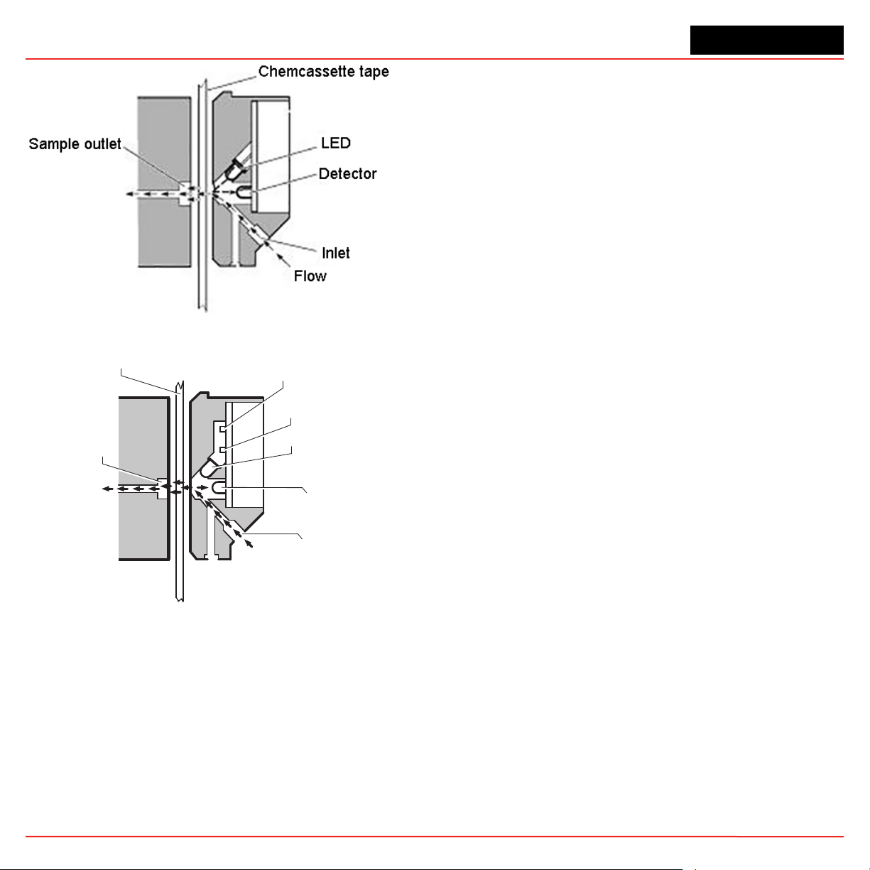
In the legacy detection system, the sample enters
the inlet and passes through the Chemcassette
tape to the sample outlet. The target gas in the
sample flow reacts with the tape and produces a
stain density proportional to the gas concentration.
An LED in the detector head illuminates the sample
stain and the detector then optically measures the
stain.
Page 22
Vertex MTM 24-Point Continuous Monitor
Surface mount LED
1.6.3 Chemcassette® Tapes
Chemcassette® tapes are tagged with a radio frequency
identification (RFID) tag to automatically identify the
following:
• Serial number
• Gas family/ tape type
• Revision level
• Expiration date of the tape
• Chemcassette® leader parameters
The module uses a leader on the Chemcassette
to allow calibration of the optics e very time a new tape
Legacy Detection System
is installed. This feature can be bypassed.
®
tape
Chemcassette tape
Sample outlet
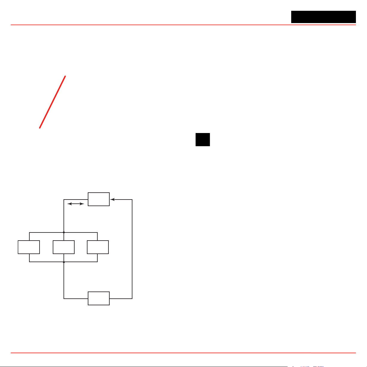
CLO Detection System
Reference detector
Light pipe
Detector
Flow
Inlet
In the Closed Loop Optics (CLO) detection system,
a reference detector monitors and controls the
intensity of the LED.
The microprocessor in the Chemcassette analyzer
module interprets the stain. It then calculates and
stores a precise concentration level in the module’s
memory. Gas concentrations are reported in
parts-per-million (ppm), parts-per-billion (ppb) or
milligrams-per-cubic-meter (mg/m3).
1.6.4 Optional ChemCam
The ChemCam is a small video camera located
between the take-up reel and the optic head on the
module. It provides a means to observe alarm level
stains.
1.6.5 Sample Filters
The Chemcassette® module includes three types of
filters in the sample flow system. Particulate filters
protect the internal precision orifice from dust particles.
An acid filter is used on the common line to the pumps.
Both types of filters are located in a removable filter
block on the side of the Chemcassette® module. An
internal particulate filter protects each proportional
valve.
Section 1 - Introduction 1-15
Page 23

Vertex MTM 24-Point Continuous Monitor
1.7 Pyrolyzer Module Detection
System
The pyrolyzer module is similar to the standard
Chemcassette
trifluoride (NF
temperature heater (pyrolyzer) which converts the
NF
to hydrogen fluoride (HF). The hydrogen fluoride
3
is then detected with a standard or XPV mineral acids
Chemcassette® tape. Detection is identical to the
Chemcassette
The correlation algorithm between HF and NF3 is
programmed into the module so the monitor displays
the NF
concentration.
3
The Vertex M pyrolyzer module detects NF3 only and
cannot be bypassed to detect mineral acids.
The right filter compartment houses eight par ticulate
filters and one acid scrubber, which are identical
to the standard Chemcassette
compartment houses eight charcoal filters which
remove the following compounds:
Freon® is a registered trademark of E.I. du Pont de Nemours &
Company (DuPont).
The charcoal filters may also remov e other compounds.
Contact Honeywell Analytics for a complete list.
Charcoal filters have a part number (P/N 1874-0139)
unique to the pyrolyzer module.
The Vertex M Pyrolyzer requires two adjacent slots on
one tier and always occupies Slot 1 and 2. The bottom
rail and latch must be removed from slot 1 to install
pyrolyzer.
®
module except that it detects nitrogen
). The sample passes through a high
3
®
module.
®
filters. The left filter
Freon 12 Freon 113 HF
Freon 13 Freon 114 HCl
Freon 21 Freon 116 Cl
2
1.7.1 Pyrolyzer Fan
The Pyrolyzer has a fan that provides cooling to the
pyrolyzer.
1.8 Vacuum Pumps
Two field-replaceable pumps provide a redundant
vacuum source for the transport and sample flow
system. One pump in the system dra ws v acuum while
the other is idle. The pump exhaust connects to the
manufacturing facility central toxic exhaust system.
Note:
The exhaust line from the Vertex M should not exceed 50 feet.
The pumps are located in the bottom of the Vertex M
System cabinet inside a sound-deadening enclosure
to reduce noise. Three cooling fans circulate air over
the pumps.
The Vertex M System draws cooling air in through a
filter mounted on the pump module access door.
Pump Status Indicator
See Pump Status Indicator under Section 4.3.1 System
Display Area.
1.9 Multiple Gas Monitoring
A Vertex M System equipped with two or more types
of Analyzer modules can monitor more than one gas
(or groups of gases such as hydrides or mineral acids)
at a location.
Each Vertex M Analyzer module can monitor only one
gas family (such as hydrides or mineral acids).
Section 1 - Introduction 1-16
Page 24
Vertex MTM 24-Point Continuous Monitor
Communications
Above is a simplified block diagram of the communications
path of the control system. The analyzer modules and
PLC are microprocessor controlled and contain nonvolatile memory.
1.10.1 Data Acquisition Computer
The data acquisition computer (DAq) is the central
processor for the Vertex M System. It configures the
analyzers, stores data and provides a netw ork interface
for data transfer to other computers. System display
and operator control is through an LCD touchscreen w/
on-screen keyboard or included external keyboard.
Optional manifold for multiple-gas monitoring.
CAUTION
1.10 Control System
The Vertex M control system is a redundant system
consisting of a central data acquisition computer (DAq),
a programmable logic controller (PLC) and one or more
analyzer modules.
PLC
Primary
Communications
Alarms and Faults
Secondary
Az
Data
Communications
Prgramming
and Display
AzAz
Alarms and
Faults Should
Primary Fail
OPC on TCP/IP via Ethernet not recommended for alarm annunciation.
1.10.2 Programmable Logic Controller
The Programmable Logic Controller (PLC) is the
control system path between the DAq and the
individual analyzers. The PLC polls the analyzers for
current information, activates relays which may be
connected to external alarms and provides external
communications.
DAq
Figure 1-1. Communications Path
Section 1 - Introduction 1-17
Page 25

Vertex MTM 24-Point Continuous Monitor
Section 1 - Introduction 1-18
Page 26

Vertex MTM 24-Point Continuous Monitor
2 Installation
Vertex M TM Technical Handbook
2-1
Page 27
Vertex MTM 24-Point Continuous Monitor
2.1 Introduction
The installation and initial start-up procedure for the
Ver tex M System consists of seven steps, described
in this and the following sections:
• 2.2 Surveying the Installation Site
• 2.3 Optional Floor Mounting
• 2.4 Installing Sample Lines/Filters
• 2.5 Installing Pump Exhaust Line
• 2.6 Electrical Power
• 2.7 Data Acquisition System
• 2.8 Wiring Alarm Relays
2.2 Surveying the Installation Site
A survey of the site helps you mak e important decisions
before installing your Ver tex M System. Topics in this
section assist you with appropriate placement of the
V ertex M System and in determining if you have special
filtering needs at the sampling location.
The site should:
• Be remote from the monitored location, not
sharing the atmosphere
• Have sufficient ventilation for cabinet cooling
• Have power available
• Be indoors in an area that is not subject to wide
variations in temperature and humidity.
Note:
The specified humidity is 20–65% RH and a temperature between 59°F to 95°F (15°C to 35°C).
2.2.1 Placement of the Vertex M System
Install the Vertex M System in an environmentallyprotected setting remote from the manufacturing or
storage locations that it monitors.
Note:
Refer to the installation drawing in Appendix A Installation
Drawings for lifting/mounting information.
Section 2 - Installation 2-2
You can place the V ertex M System up to 400 ft. (122 m)
from sample locations.
2.2.2 Exposure to Dust and Humidity
Exposure to corrosive gases or materials, excess
moisture, dust and other unusual environmental
conditions could seriously hamper the Vertex M’s
monitoring ability and could damage the monitor.
Allow room around the V ertex M System f or ventilation
and servicing.
2.2.3 Sample Transport Time
Install the Vertex M System central to all 24 sample
locations to achieve equal sample transport times
during monitoring. The shorter the sample line, the
shorter the response time. If monitoring a critical
location, it may be desirab le to place the monitor near
that critical area to reduce sample transport time for that
location. See Appendix B Specifications for transport
times.
2.2.4 Monitor Dimensions
Monitor dimensions are important factors in monitor
placement. The Vertex M System is 24. in. (61 cm)
wide, 36 in. (91.4 cm) deep and 57 in. (144.8 cm) in
height. The system with 3 analyzers weighs about 550
pounds (249 kg). Allow f or 24 in. (61 cm) door s wing; 5
in. (12.3 cm) at rear and 5 in. (12.3 cm) on sides. Allo w
clearance above monitor for installing sample lines.
2.2.5 Sample Locations
Before installing the Vertex M System, evaluate the
sampling locations to determine if excessive dust
or moisture are present. An external filter must be
used in all locations. Make sure you use the correct
filter. Dust may be a result of construction as well as
manufacturing activities. Moisture ma y occur from rain
entering a line at an outdoor sampling location or from
Page 28

Vertex MTM 24-Point Continuous Monitor
condensation caused by temperature fluctuations.
Water condensation in the sample lines could cause
false alarms.
Note:
Variables such as airflow, the molecular weight and
temperature of the sample gas, and the physical
conditions of the areas being monitored influence
the placement of the sampling locations. You may
need to consult your company’s industrial hygienist or safety officer before installing sample lines to
determine your company’s policy related to sampling
locations and monitoring of the desired sample gas.
2.2.6 Sample Line Particulate Filter Use
See Appendix B Specifications to determine which filter
type should be used at the location.
2.3 Optional Floor Mounting
For added protection with optional floor mounts, prepare
floor anchors to secure the base of the cabinet and
prevent tipping. See Appendix A Installation Drawings
for floor mounting instructions.
2.4 Installing Sample Lines/Filters
Use only FEP Teflon® tubing to assure proper
sample transport. Other types of tubing are not
sufficiently inert. See Appendix B Specifications for
tube specifications. FEP tubing can be ordered from
Honeywell Analytics. This tubing is manufactured to
our own strict specifications, and has been purged
of all by-products of the manufacturing process. On
occasion, users have supplied their own FEP type
tubing. Should y ou choose to use y our own tubing, be
advised that some brands of FEP tubing off-gas small
amounts of HF, which can be detected on start up by
monitors configured for detecting mineral acids gases
(HBr, HCl, HF, NF3). Before enabling building alarm
systems, make certain that 1) you have installed the
correct Chemcassette® and 2) your monitor reads zero .
Install sample lines from each location to the top of the
Vertex M System. This procedure involves:
• 2.4.1 Sample Line Installation Requirements
• 2.4.2 Sample Line Connections
• 2.4.3 Installing Sample Line Particulate Filters
Teflon® is a registered trademark of E.I. du Pont de Nemours & Company
(DuPont).
2.4.1 Sample Line Installation Requirements
Follow the general requirements listed below when
installing sample lines.
• Sample lines should not exceed 400 ft. (122 m)
in length.
• Route all lines as direct as possible to improve
transport time. See Appendix B Specifications
for transport times.
• Avoid running sample lines through areas of
great temperature extremes, such as adjacent
to steam or chiller lines.
• Sample lines should not be crimped, bent to
less than a 12 in. (30.5 cm) radius, or placed
in an area where weight could collapse
the tubing. Sample lines should be easily
accessible for periodic inspection.
• Where possible, leave as many bends exposed
for periodic visual inspection of the line for
kinked or damaged tubing.
• Check each sample line installation for seal
integrity after completing installation of the
Vertex M System. See Section 3.8 Leak
Checking Sample Lines for the leak check
procedure. Also use this procedure to detect
leaking or severed tubing after events, such
as construction, which may have affected the
Section 2 - Installation 2-3
Page 29
Vertex MTM 24-Point Continuous Monitor
Correct - Fully Inserted
Incorrect - Not Fully Inserted
Tubing
Stop
integrity of the tubing.
• Unused sample line ports may be blocked by
the user with a plug, or a particulate filter may
be installed to keep the system clean. If using
a plug, make sure the system vacuum level is
adjusted.
• If an analyzer is installed in the Vertex with
a Chemcassette tape, the optics may need
cleaning before activating a previously unused
point.
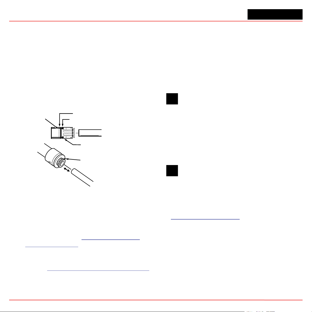
2.4.2 Sample Line Connections
O-Ring
Grey Locking Insert
install a tube into a sample line inlet, insert the tube
far enough into the fitting to ensure that the tube has
passed through both the external grab ring and the
internal O-ring and is firmly seated against the stop. The
insertion depth for a correctly installed sampling line is
1/2 in. to 5/8 in. (12 mm–16 mm). Verify the inser tion
depth by holding the tube and marking with your thumb
where it emerges from the fitting. Remove the tube to
measure the insertion depth.
CAUTION
Improper installation of the tube into the connector results in dilution of the sample.
2.4.3 Installing Sample Line Particulate
Filters
Attach a sample line filter to the sampling end of the
line for all locations.
Figure 2-1. Sample Line Inlet Connections
To prepare for installation of sample lines, remo ve the
FEP Teflon tubing from the installation kit. The top of
the unit includes 25 connections:
• 24 Sample Inlets
• Exhaust Outlet (See Section 2.5 Installing
Note:
Always perform a leak check after installing sample
lines. See Section 3.8 Leak Checking Sample Lines
for the leak check procedure.
Pump Exhaust Line for connection.)
Each inlet has a quick connect/disconnect fitting
with an internal O-ring and an external grab ring. To
Section 2 - Installation 2-4
CAUTION
Keep in mind that excess amounts of dirt in
the lters reduces the sample ow, raises
sample vacuum and may affect concentration
readings of the analyzer.
See Appendix A Specifications to determine the proper
filter type to use with each target gas.
2.5 Installing Pump Exhaust Line
This section describes exhaust connections and
installation. The Vertex M System is equipped with a
vacuum pump that is located in the bottom of the V ertex
M System cabinet. The pump exhaust line connects
to the manufacturing facility central toxic exhaust
system.
Page 30
Vertex MTM 24-Point Continuous Monitor
2.5.1 Exhaust Line Installation Requirements
Follow the general requirements listed below when
installing exhaust lines.
The length of the line should not exceed 50 ft. (15 m).
If longer distances are required, contact Honeywell
Analytics.
Do not crimp exhaust lines, or place them in an area
where weight could collapse the tubing, or bend them
to less than a 12 in. (30.5 cm) radius.
Where possible, leave as many bends exposed for
periodic visual inspection of the line for kinked or
damaged tubing.
Var ying exhaust pressure can induce pump failure or
flow faults.
2.5.2 Exhaust Line Connection
The monitor includes 20 ft. (6m) of 3/8 in. (10 mm) I.D .
x 1/2 in. (13 mm) O.D. Teflon tubing. Insert the tubing
into the exhaust port on the top of the unit to the depth
of 0.9 in. (23 mm).
System Exhaust
0.5 in (12.7mm) tubing
To ensure a leak-free installation:
• Use a polypropolene tube with outside
diameter 0.375 in. (9.525mm) +/-.005 in. (0.127mm).
• Verify that the external surface of the tube
is free of score marks and scratches that could
compromise the O-ring seal used in the fitting over
the insertion depth.
• Cut the tube end perpendicular to its length
0.062 inches (1.5 mm) from its end.
• Insert the tube in the fitting to a depth of 0.95
in. (24.13mm) ±0.05 inches (1.27mm)
With the system running, verifty the leak integrity with
a small amount of leak test fluid.
2.6 Electrical Power
The Vertex M System requires a connection to a
source of electrical power . An easil y accessible service
disconnect/power switch must be installed near the
instrument, and the switch must be marked as the main
disconnect for the V ertex M unit. The f ollowing warning
must be displayed at the switch:
CAUTION
Leaks in the exhaust tubing connection can cause
exposure to toxic gases from remote sample areas.
Section 2 - Installation 2-5
WARNING
Hazardous voltages may exist at the Alarm
Contacts in this unit with the power switch
turned off. Ensure power is disconnected at
the source prior to servicing alarm contacts.
Page 31

Vertex MTM 24-Point Continuous Monitor
2.6.1 Connecting AC Power
AC Source Requirements:
• Operating Voltage: 110 or 230 VAC ± 10%
(under load) @ 50/60 Hz; 15 Amps maximum,
single phase.
The Vertex M System requires a dedicated AC circuit
rated at either 110 or 230 volts , 50/60 Hz, 15 Amp single
phase. Line voltage should fluctuate no more than
± 10%. The e xternal switch must be clearly labeled and
installed in accordance with local electrical codes. Input
power cable should be #14 A WG minimum. The saf ety
ground wire must be the same or larger gauge as the
line wires. Connect A C pow er connection to the threeposition terminal block in the side panel of the rack.
See Figure 2-2.
AC Input
2.6.2 Power On/Off
An internal rack power switch is located behind the
door.
After performing self-diagnostics, the V ertex M System
main screen opens and the system returns to the same
state it was in prior to power down.
Analyzer / Pyrolyzer
Power Switches and Indicators
Rack Power Switch
Line
Figure 2-2. AC Power Connection
Section 2 - Installation 2-6
Neutral
Ground
Figure 2-3. Rack Power Switch
WARNING
Hazardous voltages may exist at the Alarm
Contacts in this unit with the power switch
turned off. Insure power is disconnected at
the source prior to servicing alarm contacts.
2.7 Data Acquisition System
The data acquisition computer or DAq is the main
computer in the Vertex M System. System displa y and
operator control are through an LCD touch screen with
on-screen keyboard or the exter nal keyboard on top
of the unit.
Page 32

Vertex MTM 24-Point Continuous Monitor
The on-screen keyboard operates similar to a standard
keyboard e xcept when using modifier keys (CTRL, ALT,
or SHIFT).
To use modifier keys:
1. Touch the modifier key. The key changes to
show the modifier key is locked down.
2. Press the second key of the key combination.
Figure 2-4. On-screen Keyboard
2.7.1 Printer
The Vertex M System software can be programmed
to print to either a network or local printer. To install a
local printer, connect it to the parallel printer port as
shown. You may also use the USB port. The correct
printer driver must also be installed.
2.7.2 External Network Connection
The Vertex M System can be connected to an external
Ethernet network at the port shown.
External Ethernet Connection
Figure 2-6.
CAUTION
Do not connect an external network to the
Vertex M Ethernet hub. Use only the external
Ethernet connection (as shown in Figure 2-6)
on the back of the data acquisition computer.
Connecting an external network to the hub
will impair monitoring capability.
Parallel Printer Port
Figure 2-5. Printer Connection
Section 2 - Installation 2-7
USB Port
Figure 2-7. Ethernet cable
1. When using an Ethernet output, the conduit
must be connected to Earth ground.
2. The Vertex M comes with a Ferrite. Four wraps
of the Ethernet cable is needed as close to the
Vertex M as possible.
Page 33

Vertex MTM 24-Point Continuous Monitor
2.7.3 Network Computer Security
The Vertex M relies on the HMI system of accounts
and passwords to prevent unauthorized tampering
as described in Section 4.6.6 Security Access of this
manual. Microsoft® Windows® provides its own system
of accounts and passwords. However RSView32
requires that Windows be run in an account with
administrator privileges. Attempting to run the V ertex M
RSView32 application in a Windows® account without
administrator privileges will cause error messages to
be displayed. The Vertex M should be treated and
secured as any other networked PC by maintaining
the appropriate virus protection. Contact your local
Honeywell Analytics field service representative prior
to installing Microsoft updates or Service Packs
Use an external hardware firew all to isolate the monitor
from malicious Ethernet traffic.
2.8 Wiring Alarm Relays
This section describes relay:
• Contacts
• Ratings
2.8.1 Relay Contacts
The Vertex M System has form-A, single-pole, singlethrow relays that activate external alarm devices.
Contacts are availab le for each circuit to accommodate
installation of external devices.
Relay panels are located behind the Vertex M LCD
screen. See Appendix A Optional Relay Specifications
for more information.
• Wiring guidelines
WARNING
Use caution when servicing the PLC terminal
blocks. Power to contacts is supplied exter-
nally. See Appendix A Optional Relay Speci-
cations for alarm relay voltage and contact
rating guidelines.
Section 2 - Installation 2-8
Page 34

Vertex MTM 24-Point Continuous Monitor
2.8.2 Wiring Guidelines
To wire the alarm relays:
• Use agency approved wire (such as NRTL in
the U.S.) with 300 volt insulation.
CAUTION
Make sure there is proper separation between the mains power supply and alarm
wiring.
• Route relay wiring through raceway and out
through the top of the cabinet.
• Use shielded cable or conduit.
• Conduit must be earth grounded.
CAUTION
Failure to replace and retighten hardware
after servicing can adversely affect monitor
performance and EMC compliance. Make
certain all fasteners are reinstalled and rmly
tightened. This will ensure a proper ground.
• Use a single, solid or stranded wire (not
exceeding 14 gauge or 2.5 mm2) per
terminal block connection.
• Do not switch DC current with the relay
contact unless you are using counter
electromotive force (CEMF) protection such
as a suppression diode.
• Do not use the Vertex M System power
supply for external alarm power.
Note:
Make sure all connections comply with applicable
RFI/EMI standards.
Alarm Wiring Conduit Plate
2 in (50.8mm)
Note:
The Alarm wiring conduit plate must remain in place
if not used.
Validating the System
The Vertex M and Chemcassette products’ design,
manufacture, and recommended maintenance ensure
the correct operation of the system. For validation
or commissioning after installation by gas exposure,
these Technical Notes are available upon request from
Honeywell Analytics:
1998-0837
1998-0219
Calibration and Verification
Detector Testing Protocols
Section 2 - Installation 2-9
Page 35

Vertex MTM 24-Point Continuous Monitor
Section 2 - Installation 2-10
Page 36

Vertex MTM 24-Point Continuous Monitor
3 Startup
Vertex M TM Technical Handbook
3-1
Page 37

Vertex MTM 24-Point Continuous Monitor
3.1 Startup
This section describes the Vertex M System startup
sequence.
• Sample lines
• Exhaust line
• AC power connection
3.1.1 Initial Startup
Use this section to turn on your Vertex M System and to
configure the analyzer modules f or specific gas locations.
There are six parts to this startup procedure:
• 3.3 V erify Installation
• 3.4 Power Up
• 3.5 Start Program
• 3.6 Configuration Utility
• 3.7 Load T ape
• 3.8 Leak Checking Sample Lines
• 3.9 Verify Flow Rates and Supply Vacuum
3.1.2 Factory Conguration
Honeywell Analytics loads all software on the DAq at
®
the factory . The Univ ersal Chemcassette
configured for the mineral acid f amily of gases and the
Pyrolyzer Analyzers f or NF
each point for the target gases at your facility.
. You will need to configure
3
Analyzers are
• Relay wiring
See Section 2 Installation for connection details.
3.4 Power Up
Use the rack power switch behind the front door to
power up the Vertex M System.
1. Open front door.
2. Turn on rack power switch.
3. Turn on power switch to appropriate analyzers.
4. Close and latch front door.
After 15 seconds, the analyzer status LEDs sequence
four times through all colors.
Analyzer / Pyrolyzer
Power Switches and Indicators
Rack Power Switch
3.2 Getting Started
Before startup and configuration, gather the following
information:
• The location to which each point is connected
• Target gas at each location
• Alarm levels
• Relay configuration
3.3 Verify Installation
Ahead of the startup sequence, make sure that the
following installation steps have been completed:
Section 3 - Startup 3-2
Page 38

Vertex MTM 24-Point Continuous Monitor
Mon State Alarm State Fault State
none black green
500 400 100
time in millesconds
idle
pyrolyzer
warmup
monitoring
0
1 any red black
2 any red black
0
1 any green black red
0
1
2 red green
primary program invalid amber black amber black amber black amber black amber black
unpowered black
lockup
maintenance amber black
instrument amber black
none green black
m or i green black amber
none green black
maintenance amber green
instrument amber green
red green
any
green
amber
Table 3-1. Analyzer Status LEDs
Section 3 - Startup 3-3
red
Page 39

Vertex MTM 24-Point Continuous Monitor
3.5 Start Program
Upon power-up , the DAq automatically starts Windows
and loads the V ertex M progr am. After the two-to-three
minute startup sequence, the Vertex M main screen
opens.
Note:
Any time the Vertex M System is powered up, loss
of communications may cause maintenance faults.
See Section 4.5.4 Event List for instructions to clear
faults.
Note:
Use the Windows Date/Time Properties dialog box
to change the time zone, time and date on your
Vertex M System. Stop project if adjusting time and
time zone. Once complete restart project. See Sec-
tion 4.4.5 Stopping Project on how to stop the project.
CAUTION
Do not change language in Windows setup.
Section 3 - Startup 3-4
Page 40

Vertex MTM 24-Point Continuous Monitor
Figure 3-1. Vertex M Main Screen
Section 3 - Startup 3-5
Page 41

Vertex MTM 24-Point Continuous Monitor
3.6 Conguration Utility
Before the Vertex M System can begin monitoring, you must create a configuration profile. The configuration
profile stores all of the monitor settings in a single file on the hard drive. Configuration profi les include system level
information, point settings and analyzer information. Use the Configur ation menu to create a new configur ation
profile or modify an existing profile.
To open the Configuration Menu, touch Main Screen, Menu and then Configuration.
Set Initial Conguration
Enter information and set parameters
common to all points and modules.
Congure Analyzer / Points
Defines the type of analyzer module installed in each slot.
Designates the target gas. Sets alarm levels for each point.
Dene Gas Location Names
Enter the short and long names for each monitored location.
Section 3 - Startup 3-6
Page 42

Vertex MTM 24-Point Continuous Monitor
Dene and Assign PLCs
Associate relays with software alarms and faults.
Information and Options
A display of key parameters about
the Vertex M system.
See Summary Information
A tabular listing of the
configuration profile
Section 3 - Startup 3-7
Options
Select a tab to enter information and set
parameters common to all points and modules.
Page 43

Vertex MTM 24-Point Continuous Monitor
Install Profile Status
During the installation process,
a dialog box will be shown
indicating the status and final
result of the installation.
Open Profile...
Opens a previously saved profile.
File Save/Save As...
Saves current profile on disk.
Vertex M will prompt you to save
changes when closing the
Configuration window.
Install Current Profile
Not active while creating configuration
profiles on a computer other than the
one running the Vertex M system. Loads
the current configuration settings into the
appropriate analyzers and PLCs. If the
Vertex M System is in a monitoring state,
the program will open a dialog box to verify
that it is okay to take the Vertex M System
out of monitor during the profile installation.
Close Window/Done
Exits Configuration setup
Section 3 - Startup 3-8
Page 44

Vertex MTM 24-Point Continuous Monitor
All events require User Ack
When selected, non-latching alarm
events will not be removed from the
event list until an authorized user
acknowledges the event. Fault and
latching alarm events are not affected
by this option, since an authorized
user must reset these events and a
reset also serves as an acknowledgement.
Inverted Gas Alarm Relays
Vertex M alarm relays, by default, are normally open (de-energized)
when no alarm condition exists. If this option is checked, the alarm
relays will be normally closed (energized) when there is no alarm.
Fault relays are not affected by this option and are always normally
closed (energized) unless a fault condition exists.
Non-Latching Gas Alarm Relays
A latching gas alarm relay activates when a
gas concentration reaches a level 1 or
level 2 alarm setting. The relay remains
activated until an authorized operator resets
the alarm. Non-latching gas alarm events
clear themselves as soon as the gas
concentration drops below the alarm setting.
Section 3 - Startup 3-9
Page 45

Vertex MTM 24-Point Continuous Monitor
response to the event. When utilizing data output options, it is highly
Disabled Alarm Action - Gas Relays Disabled or Full (No Gas Events)
This setting effects the operation when alarms are disabled using
the Runtime Options screen. If “Full” is selected, Vertex M will not
generate an alarm event for the affected point(s) and none of the
associated actions such as relay actuation will occur. Otherwise,
the alarm events will be generated normally when using data
output options but, the alarm relays ONLY will not be activated in
Ignore Low ChemC. Alert
Vertex M software tracks the amount
of Chemcassette
the supply reel and triggers a low tape
event when less than 24 hours of tape
remain.
Choosing “Ignore Low ChemC. Alert”
disables the low tape event.
®
tape remaining on
Section 3 - Startup 3-10
Page 46

Vertex MTM 24-Point Continuous Monitor
Set the number of days the filters will last
before they need to be replaced. When the
target is reached, this setting will trigger a
Internal Filter Life (in Days)
maintenance fault to replace filter.
Set Timeout Values
Authorized users may temporarily disable
alarms from activating and points from
monitoring. A point or alarm that is disabled
longer than the timeout limit will cause a
maintenance fault which will call attention to
locations excluded from monitoring. Enter a
period of time up to displayed minutes or 0
to disable the maintenance fault.
User Specified Auto Logout
Users remain logged in until the auto logout period lapses.
The auto logout period ranges from 30 minutes to 24 hours.
A warning displays prior to auto logout.
Section 3 - Startup 3-11
Page 47

Vertex MTM 24-Point Continuous Monitor
1st TWA Time
Use to set times for the beginning and end of each 8-hour, Time Weighted Average (TWA)
period. Use this option to associate the TWA periods with shifts or any other regular event.
The system calculates and displays the TWA after each 8-hour TWA cycle.
The default setting is 04:00 indicating that the Vertex M will run three successive TWA
periods from 04:00 to 11:59, 12:00 to 19:59, 20:00 to 03:59. Remember, the Vertex M
System uses a 24-hour clock. For example, to set the first TWA to 3:00 P.M., enter 15:00.
If you view the profile information for this example, you will see the TWA End At Time is
07:00/15:00/23:00. The system automatically sets the beginning times of the second and
third TWA periods at 8-hour intervals from the time entered for the first TWA period.
Section 3 - Startup 3-12
Page 48

Vertex MTM 24-Point Continuous Monitor
Sets the time period to maintain historical
event and concentration data before purging.
Set the purge period in Database Management
to prevent a large number of records to accumulate.
Logging Rate
The Logging Rate option sets the
frequency that Vertex M enters gas
concentration data into the
database. The system logs data at
a slow rate unless a gas concentration
rises above the threshold set in the
point configuration window. Once the
concentration reaches the threshold,
Vertex M logs at a faster rate. Logging
period options are 5, 10, 30, 60, or 120
seconds for the slow rate and 5, 10, 15,
20, 30, or 45 seconds for the fast rate.
(See Section 3.5.4, Configure Point, for
instructions to set logging frequency.)
Note:
DB Management
Setting the Vertex M System to continuously log concentration data on a 3-analyzer system requires approximately 15 megabytes of disk storage per day at the fastest logging rate of once every 5 seconds. Purge data often to
avoid filling available disk space.
Section 3 - Startup 3-13
Page 49

Vertex MTM 24-Point Continuous Monitor
Database Management-Retention Periods
Retention periods are selected as either days or weeks. Valid entries for the period are positive numbers from
1-99. Vertex M will not recalculate the values when the unit is changed. For example, if the purge period is 14
days and you change “da ys” to “weeks”, V ertex M will set the period to 14 weeks. Vertex M performs the record
purge as the data acquisition computer clock passes midnight.
Event Record Retention Period
When selected, Vertex M automatically purges
events from the database after the designated
period.
Logged Data Record Retention Period
When selected, Vertex M automatically purges
concentration records from the database after
the designated period.
Section 3 - Startup 3-14
Page 50

Vertex MTM 24-Point Continuous Monitor
Leave this box UN-checked regardless of whether a 4-20mA PLC is installed.
See Appendix G for Analog Output option configuration.
20 mA PLC Installed
Fieldbus
Use this setting to select the
PLC network interface that is installed.
Section 3 - Startup 3-15
Fieldbus Parameters
These settings allow the user to change
network specific parameters such as
address and baud rate.
Page 51

Vertex MTM 24-Point Continuous Monitor
Use mg/m3 units
Select to display concentrations in milligrams
per cubic meter. If this option is not selected,
Vertex M displays concentrations in
parts-per-million (ppm) or parts-per-billion (ppb).
User File Rev
Allows the user to assign a revision number
to a configuration profile. The profile revision
number is not associated with software
version numbers.
Profile Description
Enter a descriptive name for the
configuration profile. You may use
up to 32 characters.
Section 3 - Startup 3-16
Page 52

Vertex MTM 24-Point Continuous Monitor
3.6.1 Dene Gas Location
Use Define Gas Location to edit the list of locations. Assign a long and a short name for each location.
Clear All Entries
Clears every entry in the list.
Short names
Enter up to 12 characters. Vertex M
displays the short name where space
does not permit the display of the
long name.
Add New Entry
Creates a new entry in the gas location
list using the entered short and long names.
Long names
Enter up to 35 characters.
Replace Selected Item
Replaces the selected line in the gas
location list with the information in the
short and long name text boxes.
Delete Selected Item
Removes the selected line from the
location list.
Map Location To Point
Brings up Location Map window.
Section 3 - Startup 3-17
Page 53

Vertex MTM 24-Point Continuous Monitor
Gas Location List
Select desired gas location from this list.
For points with no assigned location,
select (default). Points assigned to default
location will automatically be given location
names based on the point’s position in the
Vertex M.
Point Map
Select point to add or remove it from the
selected location. Up to 3 points can be
assigned to each location.
Section 3 - Startup 3-18
Page 54

Vertex MTM 24-Point Continuous Monitor
3.6.2 Congure Analyzers and Points
Press “Configure Analyzer/P oints” to change the right side of the Configuration window to a display representing
physical layout of the Vertex M System. Each slot is represented by a two-part button.
When you have configured an analyzer, the top of the button displays the type of analyzer and the gas family.
The bottom of the button is a second button for configuring each point within the analyzer.
Note:
Only analyzers on tier one should be configured. Configuring analyzers on tiers 2 or 3 will result in errors and
faults.
Two-part Button
Section 3 - Startup 3-19
Page 55

Vertex MTM 24-Point Continuous Monitor
3.6.3 Set Analyzer Window
To configure the type of analyzer slot, press the top of the button representing the slot. The Set Analyz er Window
opens.
Options
When you choose a family of gases, Vertex M
enters default settings into the profile. Selecting
“Override Defaults” allows you to change the
target gas type, alarm levels and the location
assignment.
Analyzer Type
Choose the model of analyzer populating
the slot. A pyrolyzer takes up slots 1 and 2.
If pyrolyzer is selected, slot 1 automatically
becomes unavailable.
Any analyzer that is physically installed but
configured on this screen to “None” should
be de-energized.
Family/Chemcassette
Choose the family of target gases.
Target gases for all eight points in
the analyzer must be in the same
family of gases.
ChemCam AutoPicture
If the optional ChemCams are installed, select under what condition
a picture of the Chemcassette
®
stain will be automatically taken.
ChemCam AutoPicture
When either ChemCam for Level 1 or Level 2 gas is selected, a gas alarm signals the Vertex M System to
store a picture of the stain the next time it advances the Chemcassette® tape. When the tape advances, the
tape stops with the stain under the camera, the ChemCam takes a picture and then advance continues. The
ChemCam field of view is only wide enough to capture four points on one picture. See Section 4.5.3 Optional
ChemCam for additional information on ChemCam features and functions.
Note:
This activity will consume additional tape. Some faint stains may not be visible via the camera
Section 3 - Startup 3-20
Page 56

Vertex MTM 24-Point Continuous Monitor
3.6.4 Congure Point
The Configure Point window provides the following options for each point:
Select the specific target gas Configure concentration logging
Designate the location of the target gas Configure point-specific event help
Set alarm levels Set PLC full-scale concentration
Enable/disable point
When all of the entries are correct for the point, use either the point selection buttons or choose Next Point/
Last Point to scroll to the next point in the analyzer. Press Done when all settings are entered.
Gas Calibration
Select the target gas from the dropdown list.
Only the gases valid for the family of gases
chosen for the designated tape will appear.
Warning
Select Warning to create an alarm when a gas
concentration exceeds the Lower Detection Limit (LDL).
See Appendix A Detectable Gases for a complete list
of LDLs. Warnings appear as a “W” on the main screen
with no relay actions.
Last Point / Done / Next Point Buttons
Section 3 - Startup 3-21
Page 57

Vertex MTM 24-Point Continuous Monitor
Alarm Level 1 and Alarm Level 2
Ver tex M loads default alarm levels when you choose a target gas. See Appendix A Detectable Gases for a
list of default alarm levels. You may enter new levels only within the range of the Vertex M detection system.
Make the gas assignments before changing alarm levels. Changing the gas automatically resets alarm level
settings to the factory defaults.
The Vertex M System will not allow you to make invalid or inappropriate entries while setting alar m levels.
Following are three examples of invalid attempts the Vertex M System will reject:
• The alarm setting for Alarm Level 1 is greater than the setting for Alarm Level 2
• An alarm setting is less than the lowest alarm level for that target gas
• An alarm setting is greater than the full scale for that target gas
Alarm Level 1
Alarm Level 2
Section 3 - Startup 3-22
Page 58

Vertex MTM 24-Point Continuous Monitor
Log never/Log always/Log if
This option sets the frequency that
Vertex M enters data into the data log.
PLC F/S Conc. (Data Output)
Calibrates the Vertex M current loop output or
data concentration bits to correlate to the
customer-specified output range (i.e.; milliamp
output scaling or data output scaling to
external PLC). Factory default value sets the
20 mA point to two times the TLV which is
typically lower than the full scale value of the
gas calibration (i.e.; F/S)
Log Always Log if >= Log Never
If concentration
is below
configured
threshold
If concentration
is equal to or
greater than
configured
threshold
Note:
logs at slow
rate
logs at fast rate
not logged not logged
logs at fast
rate
not logged
Setting the Vertex M System to continuously log concentration data on a 3-analyzer system requires approximately 15 megabytes of disk storage per day. Purge data often to avoid filling available disk space.
Section 3 - Startup 3-23
Page 59

Vertex MTM 24-Point Continuous Monitor
Units
Selects the unit of measure to display target gas concentrations.
This selection applies to this screen only and does not effect
displays during normal operation or events.
Unit choices are:
PPx
Parts-per-million or parts-ber-billion.
See Appendix A Detectable Gases
for definition.
Displays target gas as a percentage
of the threshold limit value. See
Appendix A Detectable Gases for a
list of the TLV for each target gas.
Displays target gas concentration
as a percentage of the full-scale
concentration.
See Appendix A Detectable
Gases for a list of the full scale
concentration for each target gas.
Displays gas concentration
in milligrams per cubic meter.
%TLV
%F/S
mg/m3
Section 3 - Startup 3-24
Page 60

Vertex MTM 24-Point Continuous Monitor
Check this box to perform a sample line integrity test.
P
erform Optional Line Integrity Test
See Appendix A Line Integrity Test Option.
Disable Point
No Monitoring
Select “Disable Point”
for points not needed.
Associated (*.HTM) File
You may link a user-generated HTML file
to this point. Either type in the file name
or touch the browse (…) button to bring
up a file selection window.
Gas Locations
Use this field to label the location the
point is monitoring. You may assign a
name by one of three methods:
* Choose a name from the location list.
See “Define Gas Location” for entering
names in the list.
* Edit the selected location.
Create a new location.
*
Section 3 - Startup 3-25
Page 61

Vertex MTM 24-Point Continuous Monitor
Generate Window Zero
Reset Faults
Window Zero Reset events
are generated when unusual optics readings occur.
Usually these are one-time
events and present no long
term issues. By default,
these events generate an
informational event. However, these events can sometime indicate conditions
that could lead to a false
concentration readings.
For that reason, this option
is provided. If selected, a
maintenance fault will be
generated when a Window
Zero Reset event occurs.
Generate Accelerated CC
Usage Faults
If a low background level of
gas is present that is below
the lower detectable limit,
a stain can develop on the
tape while the Vertex reports zero concentration.
This can cause the Chemcassette to be used up
faster than expected. If the
option is enabled, a maintenance fault will be generated if this condition exists.
PLC Network
Use to set communication parameters for the optional PLC Network interface.
F.8 DF1 Interface (P/N1295-0343)
F.9 Modbus Plus Interface (P/N1295-0330)
Generate Sub-LDL
Events Generates a
warning alarm with 0
ppb/ppm concentration
that may indicate the
presence of gas below
LDL.
Virtual Reference
Function See the
following page.
Line Integrity Test
Displays the optional Line
Integrity Test configuration
utility. See Appendix H -
Line Integrity Option.
Section 3 - Startup 3-26
Page 62

Vertex MTM 24-Point Continuous Monitor
Virtual Reference Function
The Virtual Reference option reduces the possibility
that a non-gas event will result in a concentration or
alarm. When enabled, it maintains a record of specific monitor operation and, in the event of a reading
¼ TLV or above, executes a confirmation before the
concentration or alarm is issued. Once confirmed,
measurements for the same event will not be affected. See software 1.25.5 release technote for further
information.
The Virtual Reference function is user configurable
by rack (it is disabled by default). See the following
table for the number of windows used and the time to
confirm an event. The function reduces the possibility
that a non-gas event will result in a concentration or
alarm.
Note:
The Virtual Reference function is not used on
CLO analyzers, even if enabled.
Hydrides 3 15-25
XP Hydrides 3 15-25
Mineral Acids 6 30-40
Cl2/Oxidizers (NO2) 6 30-40
Mineral Acids (Pyro) 6 30-40
Phosgene 6 30-40
XP Phosgene 6 30-40
Aliphatic Amines 3 15-25
Cl2/Oxidizers-III 6 30-40
Hydrogen Cyanide 3 15-25
Hydrogen Sulfide 3 15-25
XPVChlorine 6 30-40
Fluorine/Oxidizers 3 15-25
XP Ammonia 3 15-25
XP Mineral Acids 6 30-40
XPVMineral Acids (Pyro) 6 30-40
LL Sulfur Dioxide 3 15-25
XP4 Hydrides 3 15-25
XP4 Mineral Acids 6 30-40
XP4 Mineral Acids (Pyro) 6 30-40
XP4 Chlorine 6 30-40
XP4 Ammonia 3 15-25
XP4 Phosgene 6 30-40
Chemcassette
Number of
Windows
Pulled
Time to
conrm
(sec)
Section 3 - Startup 3-27
Page 63

Vertex MTM 24-Point Continuous Monitor
3.6.5 Dene and Assign Relays
The Vertex M System includes multiple programmab le relays. You may associate relays with one or more alarms
or faults to trigger external alarm devices or emergency equipment. Relays are located on relay cards; either
8 or 16 relays populate each card.
Note:
Relays are NOT factory configured.
Vertex M uses a two-part display to configure rela ys . The Configure PLC window displa ys the a v ailab le rela y cards
and contacts. In a second windo w, Vertex M also displays a representation of the analyzers installed in the system.
See Appendix A Optional Relay Specifications for a complete listing of alarm relay specifications.
Section 3 - Startup 3-28
Page 64

Vertex MTM 24-Point Continuous Monitor
3.6.6 Congure PLC
Use Configure PLC to enter the following:
• The number of relay cards installed
• The number of contacts per card
• The number of relays designated as fault
relays.
PLC Relay Cards
Up to 4 relay cards populate the V ertex M System. The
cards are numbered 3-6.
Relays per Card
Relays are located on rela y cards; either 8 or 16 rela ys
populate each card.
• Cards with 16 relays share a common
connection among groups of eight contacts.
• Cards with 8 relays have 8 isolated pairs of
contacts.
Clear All
Erases the alarm and
fault relay definitions
Set Default
Sets all relays to the
initial default mappings
Section 3 - Startup 3-29
Fault Relay Count
You ma y allocate from 2 to 16 rela ys for fault indicators.
Note:
Set the number of fault relays before setting alarm
relay definitions. If you change the number of fault relays, the current relay definitions become invalid and
must be redefined.
When you change the number of f ault relays, Vertex M
opens the Fault Relay Definition Change dialog box.
Choosing Yes shifts the alarm definitions, choosing No
pads the alarm definitions. Choose Cancel to return
Page 65

Vertex MTM 24-Point Continuous Monitor
to the PLC configuration without changing the relay
assignments.
Changing the number of fault relays from 14 to 12 will
result in two additional (and undefined) alarm relays
being available at card 3 relays 12 and 13. Existing
relay definitions are not moved.
3.6.7 Set Alarm Relays
A relay configured f or a Level 1 trigger will activate for
both Level 1 and Level 2 alarms. A Level 2 trigger will
only activate for Level 2 alarms.
Shift
Alarm relay definitions move down to fill the space
created by fe wer fault relays or mov e up to accommodate
the additional fault relays.
Changing the number of fault relays from 14 to 16 will
cause the alarm relay assignments to move two rela ys
up. Card 5, relay 2 definition moves to card 5, relay 4;
card 5, relay 3 mov es to card 5 rela y 5; card 5 rela y 15
moves to card 6, relay 1, etc.
Changing the number of fault relays from 16 to 14
moves relay assignment down by 2 positions. Card
5, relay 4 definition moves to card 5, relay 2; card 5,
relay 5 moves to card 5 relay 3; card 6, relay 1 moves
to card 5, relay 15, etc.
Pad
Padding lea ves most alarm relay definitions unchanged.
Some existing alarm definitions may be ov erwritten or
undefined relays may become available.
Changing the number of fault relays from 14 to 16 will
cause the alarm definitions on card 3, relay 14 and
card 3, relay 15 to be overwritten by the fault relay
assignments.
None of the relays are defined as general or point
specific alarms until they are programmed or associated
with one or more points in an analyzer.
Note:
Set the number of fault relays before setting alarm
relay definitions. If you change the number of fault relays, the current alarm relay definitions may change
and must be redefined. See Section 3.6.6 Configure
PLC.
Defining a point for association with a relay is a fourstep process:
1. Choose the relays to which you want to
associate with a point.
2. Choose L1 Alarm or L2 in the Change To...
area.
3. Click the square representing the point or
points to associate with the relay. The point
changes color to indicate the change.
4. Choose Accept make the change the change
to the configuration profile. Choosing cancel
leaves the alarm definition unchanged.
Repeat the steps for all contacts.
To verify a contacts association to analyzer points,
choose the contact. The associated point display
changes color.
Section 3 - Startup 3-30
Page 66

Vertex MTM 24-Point Continuous Monitor
definitions from relays
Clear all alarm
Squares that represent the point or
points to associate with the relay
Selected relay in
the relay block
Section 3 - Startup 3-31
Set type of alarm
Page 67

Vertex MTM 24-Point Continuous Monitor
3.6.8 Set Fault Relays
Fault relay contacts activate for instrument or
maintenance faults. F aults are associated with an entire
analyzer and not individual points.
• Instrument faults indicate a loss of monitoring
on one or more points.
• Maintenance faults indicate the Vertex M
System requires attention but is continuing to
monitor.
Note:
The number of relays used for fault indication is configurable. See Section 3.6.6 Configure PLC.
Defining an analyzer for association with a relay is a
four-step process:
1. Choose the relays to which you want to
associate with an analyzer.
2. Choose Instrument, Maintenance, Both or
None in the Change To... area.
3. Click the square representing the analyzer
or analyzers to associate with the relay.
The square changes color to indicate the
association.
4. Choose Accept to modify to the configuration
profile. Choosing Cancel leaves the alarm
definition unchanged.
Repeat for all relays.
T o v erify a relay’ s assignment to analyzers, choose the
contact. The associated analyzer changes color.
Section 3 - Startup 3-32
Page 68

Vertex MTM 24-Point Continuous Monitor
Clears all fault definitions
from all relays
Selected relay in
the relay block
Square that represents the
analyzer or analyzers to
associate with the relay
Section 3 - Startup 3-33
Set type of fault
Page 69

Vertex MTM 24-Point Continuous Monitor
3.6.9 Prole Management-File Menu
Use the file menu to open, create, save or close a
configuration file. Configuration files may be stored in
3.6.10 Other Menu
The Other Menu offers several shortcuts to speed
configuring the Vertex M System.
any directory on the Vertex M System hard disk.
When you make any changes to the configuration
profile, Vertex M will always prompt you to save the
change before closing the Configuration window.
Copy Az definition
Copies the configuration
of one analyzer to any
other analyzer in the
system. There are two
options when copying an
analyzer configuration:
Copy Gas Location Name
Copies the location from the
first analyzer to the second
analyzer.
Copy *.htm File Name
Assigns the instruction file for
the first analyzer to the second
analyzer.
Alarm Defaults
Sets the level 1 and level 2
alarms of all analyzers not
yet configured to the following
values:
* One-half TLV and TL V
* TLV and two times TLV
* One-half TLV and two times TLV
Section 3 - Startup 3-34
3.7 Load Tape
After configuring the analyzers, load each analyzer with
the proper Chemcassette® tape required for the target
gas. See Section 5.3.4 Change Chemcassette® Tape
for loading procedure. See Detectable Gases, for a list
of target gases and Chemcassette® tape part numbers.
After installing Chemcassettes® for initial configuration,
keep the analyzer in IDLE mode. Do not move to
monitor mode until you have:
Performed a leak check on sample lines . See Section
3.8 Leak Checking Sample Lines.
Verified flow rates See Section 3.9.1 Verify Flow Rates.
Page 70

Vertex MTM 24-Point Continuous Monitor
3.8 Verify Flow Rates and Supply
Vacuum
After you have configured all analyzers, loaded
Chemcassettes
verify flow rates in the Flow Diagnostics Window . F rom
Main Screen, touch Menu, Service, Authorized Service.
The Authorized Service window opens.
Note:
At higher altitudes with many analyzers installed, the system
(50 Hz. mains) may not be able to achieve 13” Hg.
®
and performed leak check, you will
3.8.1 Verify Flow Rates
The Authorized Service window displays the flo w range
in bar graph form f or each point of the selected analyzer.
Choose the analyzer from the selection pad in the upper
right-hand corner. Press the pump on button. The eight
points display their flow.
Section 3 - Startup 3-35
Page 71

Vertex MTM 24-Point Continuous Monitor
Flow (cc/min)
The real-time sample
flow to the point.
Point Vacuum (in Hg)
Point Vacuum indicates the
restriction from sample line
length and the pressure
developed by shared lines.
Supply Vacuum
Typical supply vacuum is
9-12 in. Hg
Selection Pad
Section 3 - Startup 3-36
Optional Line Integrity Test Option
See Appendix A Line Integrity Test Option
Page 72

Vertex MTM 24-Point Continuous Monitor
Target Flow
A horizontal red line indicates the target
flow rate required by the Vertex M System
for correct analysis. The target flow rate is
180 cc/min. +/-5% (171-189 cc/min.)
Section 3 - Startup 3-37
Flow Rate
A floating white box indicates the actual
flow rate. The position of the box graphs
the flow; the numerical value of the flow
is displayed in the box.
Page 73

Vertex MTM 24-Point Continuous Monitor
Minimum Flow
The minimum flow possible with
the attached sample line and orifice.
Proportional Value Range
A vertical green bar displays the dynamic
range over which the proportional valve
can adjust the flow rate. Indicated numerically
by Minimum Flow and Maximum Flow.
Maximum Flow
The maximum flow possible with
the attached sample line and orifice.
See Section 4.6.2 Flow Calibration for
instructions on adjusting flow rates.
Section 3 - Startup 3-38
Auto Balance
Page 74

Vertex MTM 24-Point Continuous Monitor
3.9 Leak Checking Sample Lines
Perform a leak check of the sample lines following
installation and also whenever a line is changed or
moved. The leak check procedure involves plugging
the end of the sample line and verifying that there is
no flow through the line. To perform a leak check:
1. Put the affected Analyzer in Idle mode.
2. Choose Main Screen, Menu, Service,
Authorized Service.
3. Select Analyzer.
4. Press pump on.
5. Securely plug the end of the sample line being
tested.
6. Verify that the flow rate for the test line drops to
zero. See Flow (cc/min) on page 3-36.
7. Verify that the sample Point Vacuum equals
the Supply Vacuum within a tolerance of +/-0.5
inches Hg (see Point Vacuum (in Hg)) on page
3-36.
8. “Verify that the sample flow is less than 20cc.”
“See Flow (cc/min)” and “(see Point Vacuum (in
Hg)) are links.
9. After testing all points on the selected analyzer,
press Pump Off.
If the sample point passes the test with the top port
plugged, the leak is somewhere in the sample line and
the line must be replaced. If the sample point fails the
leak check procedure with the top inlet port plugged,
contact Honeywell Analytics for assistance.
3.10 Recongure
The modular design of the Vertex M allows limited
reconfiguration. All wiring and tubing is in place behind
unpopulated slots. To add modules:
1. Remove filler panel.
2. Install new analyzer. See Section 5.4
3. Configure new analyzer. See Section 3.6
4. Load tape. See Section 3.7 Load Tape.
5. Leak check sample lines. See Section 3.9 Leak
6. Verify flow rates. See Section 3.8 Verify Flow
Note:
Replacing an Analyzer.
Configuration Utility.
Checking Sample Lines.
Rates and Supply Vacuum.
Any analyzers which are physically installed but not
included in the configuration should be de-energized.
Note:
You must touch the Pumps On button even if the
pumps are operating. Touching Pumps On turns on
the solenoid valve to provide vacuum to the analyzer.
A sample point failing to meet both the flow and v acuum
conditions of step 7 indicates either a leak in the sample
line or a faulty sample inlet connection.
To troubleshoot the condition, disconnect the sample
line at the inlet port at the top of the Vertex M cabinet.
Securely plug the inlet port and repeat the above leak
check procedure.
Section 3 - Startup 3-39
Page 75

Vertex MTM 24-Point Continuous Monitor
3.11 Moving to a New Site
Before moving the Ver tex M to a new site, use the
following procedures to pre vent loss of data or damage
to the monitor.
1. Remove all Chemcassette® tapes and store
as required by local policies.
2. Exit the Vertex M program. Touch Project and
then Stop Project.
3. Back up data and configuration files. See
Section 5.10 File Maintenance.
4. Open the front door and set all power switches to
“Off”.
5. Disconnect electrical supply at the source and
then disconnect from the power terminal in
the side of the cabinet.
6. Disconnect sample lines and cap lines as
required by local policies also cap Vertex M
inlet points.
7. Disconnect exhaust line and cap line as
required by local policies.
CAUTION
Leaks in the exhaust tubing connection can cause
exposure to toxic gases from remote sample areas.
For leak-tight connections, follow the instructions in the
Installing Pump Exhaust Line
Pump
integrity with a small amount of leak test fluid.
section. With the system running, verify the leak
section and the
Remove
8. Disconnect alarm relays.
WARNING
Hazardous voltages may exist at the Alarm
Contacts in this unit with the power switch
turned off. Insure power is disconnected at
the source prior to servicing alarm contacts.
Crate and pad the V ertex M to prevent damage during
transport. If unsure of packing requirements , contact
the Honeywell Analytics Service department.
Section 3 - Startup 3-40
Page 76

Vertex MTM 24-Point Continuous Monitor
System Shutdown
CAUTION
Failure to properly shut down the Vertex M could result in system le corruption.
1. Exit the Vertex program. Touch Project and then Stop Project.
2. In the Windows taskbar touch Start and then Shut Down.
3. Open touch screen and set all switches and the rack power switch to “Off”.
Section 3 - Startup 3-41
Stop Project
Project
Page 77

Vertex MTM 24-Point Continuous Monitor
4 Operation
Vertex M TM Technical Handbook
4-1
Page 78

Vertex MTM 24-Point Continuous Monitor
4.1 Introduction
This chapter describes Vertex M operation including
monitoring, system control and data viewing.
This chapter includes the following sections:
• 4.2 Monitoring Mode Overview
• 4.3 Main Screen
• 4.4 Project Functions
• 4.5 Review Functions
• 4.6 Menu Buttons
• 4.7 OnScreen Keyboard
See Section 3 Startup if the analyzers in the Vertex M
System have not yet been configured.
4.2 Monitoring Mode Overview
Monitor mode is the Vertex M System’s standard
operating state. Upon power up, the monitor perf orms
initialization routines and returns to the same state as
when powered down. During monitoring, the Vertex M
System will calculate concentrations ev ery second for
each of the enabled points. Concentrations are used for:
• Triggering alarm relays
• Viewing in the main screen
• Entries in the event list
• Viewing in point detail screen
Concentration information is available through the:
• Point detail screen
• OPC
• Optional fieldbuses
• Optional 4-20 mA output
• Data logger
Section 4 - Operation 4-2
Page 79

Vertex MTM 24-Point Continuous Monitor
4.3 Main Screen
The Vertex M System opens the main screen after power up. Vertex M divides the main screen into three
areas:
• System display
• Point detail
• Function buttons
Point Detail
System Display
Section 4 - Operation 4-3
Function Buttons
Page 80

Vertex MTM 24-Point Continuous Monitor
4.3.1 System Display Area
The System Display Area displays information about all of the points in the Ver tex System. Each of the 72
blocks in the System Displa y Area represents one point. A group of eight blocks represents an analyz er b lock.
The analyzer block has the status bar indicator at the top of the block. A pyrolyzer displays as a blue block in
slot 1 and points detail in slot 2.
The System Display Area positions the modules in the same order in which they are ph ysically located in monitor.
The currently selected point displays a green border. If more than one point has the same gas location as the
selected point, all points in same location display with green border.
Universal
Chemcassette
Analyzer
Section 4 - Operation 4-4
System Display
Page 81

Vertex MTM 24-Point Continuous Monitor
Status Indicators
The indicator displays brief information about analyzer
status such as faults, warnings or maintenance
functions in process.
Point 1
Point 2
Point 3
Point 4
Point 5
Point 6
Point 7
Point 8
Status indicators include:
• IDLE - the analyzer is not monitoring or
performing maintenance
• MONT - the analyzer is monitoring
• LD CC - Load Chemcassette® routine is in
progress
• PROG - a new application program is being
loaded into the analyzer
• CONF - a new configuration is being loaded
into the analyzer
• COMF - a communications failure between the
DAq and the analyzer
• PYRO-W - a pyrolyzer analyzer is warming
up. When pyrolyzer has reached stable
temperature, it will automatically go into
monitor
The Vertex System displays only the short names of
the location and target gases within each point block.
During normal monitoring, the background color of each
block is white. Vertex will change the background color
of a point as conditions change.
White Normal operation.
Blue
Grey
Red
Alarms for the point are disabled in
the runtime options menu.
Point is disabled in the runtime menu
or is disabled due to a fault.
Gas concentration exceeded an
alarm level.
Purple Disable configuration alarm
Black
Point is not configured for
monitoring.
Table 4-1.
Alarm Indicators
When the target gas concentration for a point reaches
a preset alarm level, Vertex will display a W, 1 or 2 in
the point block to indicate the severity of the alarm.
Alarm
Indicator
W (if enabled) Lower Detectable Limit (LDL)
1 Alarm Level 1
2 Alarm Level 2
Concentration Threshold
See Section 3.6.4 Configure Point for information on
setting Alarm Level 1 and Alarm Level 2.
See Section 3.6.10 Other Menu for information on
alarm default values.
• FLOW - a flow Auto Balance procedure is in
process on the analyzer
Section 4 - Operation 4-5
Page 82

Vertex MTM 24-Point Continuous Monitor
Pump Status Indicator
The Vertex Display includes pump status indicators in
the top right corner. The bottom row indicates which
of the pumps is currently operating. The indicator will
display “ON” with a green background if the pump is
operating and “OFF” on a white background if the pump
is not running.
The top row indicates what is known about pump
health. The indicator will display “GOOD” with a green
background if the pump has successfully provided
proper levels of system vacuum. If the Indicator
displays “BAD” on a red backg round, this indicates that
pump related faults 112 or 219 have been generated.
The indicator may display “UNKNOWN” on a white
background after software is installed or after analyz ers
are added or moved into a different location.
Pumps in the “UNKNOWN” or “BAD” state change to
the “GOOD” state only when successfully used during
gas monitoring. After a f ailed pump has been repaired
or replaced, it can be exercised by pressing “PUMP
ALTERNATE” button while monitoring. See Section
4.6.2 Flow Calibration. If successful, the pump state
will change to “GOOD”.
Honeywell Analytics recommends that pumps be
alternated periodically to insure availability according
to your facility’s schedule.
Pump Health
Indication
Pump Status Indicator
Pump Operation
Indication
Section 4 - Operation 4-6
Page 83

Vertex MTM 24-Point Continuous Monitor
Fault Indicators
In addition to changing color, an event window opens indicating a new event.
A yellow square inside the status bar in the analyzer block indicates an analyzer-specific fault.
A yellow square inside of the point block indicates a point-specific fault.
• See Section 6.3 Maintenance Faults
• See Section 6.5 Information Events
M - Indicates a
maintenance
fault
F - Indicates
an instrument
fault
Section 4 - Operation 4-7
Page 84

Vertex MTM 24-Point Continuous Monitor
4.3.2 Point Detail Display Area
The Point Detail Area (see Figure 4-1) displays
comprehensive information about each location.
Touching a block in the System Display Area displays
the current information about a location.
Cong File
User ID
Location
Tier-SlotPoint
Point. Points not needed for monitoring may
The configuration profile file name
The name of the current, logged in
user
The short name of the sampled
location
Points are identified by the tier, slot
and their point number in which the
analyzer is installed
be disabled. A disabled point does not
trigger alarms
• See Section 4.5.4 Event List
• See Section 4.5.2 Data Trend
• See Section 4.5.1 Event History
Section 4 - Operation 4-8
Figure 4-1.
Page 85

Vertex MTM 24-Point Continuous Monitor
Figure 4-2 is an image of the P oint Detail section of the
main Vertex display screen snapshot
Analyzer
Points /
Alarms
Gas Data
Point Color
Legend
The analyzer type
A point may be enabled but the alarm may
be disabled
Name of the gas or gases, up to three
gases per location
Current concentration for each gas
Alarms, if any, for that point and gas. This
field shows “on” or blank.
This legend defines the background
colors in the system display area
Note:
A Vertex System equipped with two or more analyzer
modules can monitor up to three different gases per
location. However, you may not program an analyzer
for more than one gas family at a time. When you
configure the Vertex System for multiple gases per
location, touching a point on the system display area
will also change the border on other points monitoring the same location. The information for a location
displayed in the point detail area will be identical
regardless of which point is selected in the system
display area.
Section 4 - Operation 4-9
Figure 4-2.
Page 86

Vertex MTM 24-Point Continuous Monitor
4.3.3 Function Buttons
Use the function buttons located under the point detail
area to access the following areas.
Menu - Perform runtime changes, flow
calibration, maintenance, diagnostics and
service functions, edit security settings and
configure the system.
Review - View stored historical gas
concentration data or events and access
ChemCam.
Project - Log in, log out, change passwords,
update programs and stop the project (exit
Vertex M).
Help - Opens a window to explain the
functions of the main screen.
4.4 Project Functions
Use Project functions to log in, log out, change
passwords, update programs, restore the keyboard
and stop the project (exit Vertex M).
Section 4 - Operation 4-10
Page 87

Vertex MTM 24-Point Continuous Monitor
4.4.1 Log In and Log Out
T o protect the integrity of the system, the V ertex System
classifies menus as either open or protected functions.
If you require access to a protected menu, you must
log in under a user account with permission to use that
menu. The V ertex System administrator assigns access
to protected functions by setting up user accounts.
See Section 4.6.6 Security Access for more information.
Logging In
Figure 4-3. Login
To log in, choose Main Screen, Project and then Log
In. The Login window opens. Enter your user account
name and password followed by Enter.
The Vertex System will automatically log out any user
after a period of inactivity. The default timeout period
is 8 hours. Authorized users may change the timeout
setting in the Configuration Menu.
Thirty seconds prior to the end of the timeout per iod,
Vertex will warn before logging out a user.
4.4.2 Changing Password
You ma y change your passw ord at anytime. To change
your password:
1. Login with old password.
2. Touch Project and then Change Password.
3. Enter old password.
4. Enter new password in both text boxes.
5. Touch Enter.
If both new passw ords are identical, Vertex will accept
your new password.
After you log in, the system checks your access
privileges. As you use Vertex men us, only the buttons
to which you have access will be active. The buttons
associated with functions to which you are denied
access are dimmed.
A user can choose Logout to select the default user
account.
Logging Out
To log out, choose Main screen, Project and then
Logout. A Log Out confirmation window appears.
Simply click OK to close the window.
Section 4 - Operation 4-11
Figure 4-4. Password Change
Page 88

Vertex MTM 24-Point Continuous Monitor
4.4.3 Updating Program
Contact Honeywell Analytics for details.
4.4.4 Restore OnScreen Keyboard
Use the OnScreen Keyboard button to restore the
keyboard if it becomes hidden.
OnScreen
Keyboard
Button
4.4.5 Stopping Project
Use Stop Project to exit the Vertex M program. Touch
Project and then Stop Project.
Even though the Vertex M program is not running,
individual analyzers continue to monitor and store data
in their internal memory.
4.5 Review Functions
Section 4 - Operation 4-12
Use Review functions to view information stored in
the Vertex M System database. Available for viewing
through the Review menu are:
• View currently active events using Event List.
• View historical events using Event History.
• View historical or real time concentration data
through the Data Trend window.
• Access ChemCam functionality.
Page 89

Vertex MTM 24-Point Continuous Monitor
4.5.1 Event History
An event is an y action that the V ertex System is required to enter into the database. As events occur , the Vertex
System stores the events in a database on the DAq PC. The default database format is Microsoft Access.
Use the Event History Window to sort and filter data in the event log.
Figure 4-5. Event History
Events include but are not limited to:
• Alarms and faults
• User log in and log outs
• Configuration changes
• System maintenance
• Security changes
• Time and date of power up
• User comments
The peak concentration during an alarm is reported in
the Conc/Data field of the reset event. This supplements
the concentration reported in the Alarm event, which is
the first concentration reported by the Vertex after an
alarm threshold is first exceeded.
Section 4 - Operation 4-13
Each event record contains the following minimum
information:
• Date and time of the event
• Module name
• An event message which may include alarm
status, user login state or a comment.
• Logging station computer name
To view the event log, choose Main Screen, Review
and then Event History.
Unless sorted, Ver tex displays events in descending
order with the most recent event at the top of the displa y .
Page 90

Vertex MTM 24-Point Continuous Monitor
Sort Options
Sorting arranges
data according
to the values in
one of the sort
lists. The default
sorting of events
is chronologically
with the most
recent events
first.
If the data base
is large, the sort
may take a while.
Filter Options
Apply filters to find a subset of events
in the log. A filtered list displays only
the rows that meet the criteria you
specify.
Note:
Changes to sort and filter options
will not take effect until you press
Apply/Refresh.
Section 4 - Operation 4-14
<< >>
Horizontal scroll
to show additional
fields.
Figure 4-6. Event History
Apply/Refresh
Touch to apply the
selected sort or filter
or filter options.
Page Up/Page Down
Vertical scroll to show
additional records.
Page 91

Vertex MTM 24-Point Continuous Monitor
Print
Display All
Removes filtering.
Figure 4-7. Event History
Section 4 - Operation 4-15
Prints current
query. Before
printing, note that
Event History
can be quite
long. The “total”
figure shows the
number of events.
Save
Saves current query to
an Access database.
Page 92

Vertex MTM 24-Point Continuous Monitor
Date elds
Defaults to
current date. The
default range is
current date and
the previous two
weeks.
Maximum Records
Use to limit the number of
records to display . V ertex will
display up to 10,000 records.
The default setting is 500.
Use the up and down arrow
buttons to increment the
value by 100.
Figure 4-8. Event History
Advanced Filter Options-Events
Use to filter on specific alarms, faults or other events.
Section 4 - Operation 4-16
Advance Filter Options
Use the Advance Filter Option
buttons located to refine the
sort.
Page 93

Vertex MTM 24-Point Continuous Monitor
Figure 4-9. Filter Options
Section 4 - Operation 4-17
Page 94

Select Filter Options-Modules
Use to filter events based on specific points, analyzers or other hardware modules.
Figure 4-10. Filter Options
Page 95

Select User ID or Logging station
Use to select a specific Vertex station or operator.
Figure 4-11. Selecting Station or ID
Page 96

Vertex MTM 24-Point Continuous Monitor
4.5.2 Data Trend
Vertex plots gas concentration in the Data Trend window. You may choose multiple points to plot each point a
different colored line on the graph. Data displayed in the graph can be either Stored data from the data log or
Live (a continuous, real-time display, scrolling right to left).
Data can only be stored if datalogging was selected in the Profile Management Utility screen. A maximum of
one year of data can be stored, however faster datalogging rates may require more frequent purging. Stored
data shows only concentration (not location names)
Drag a finger across the
TIP
screen to zoom into the
area selected
Information for each point appears in the table to the left of the graph.
Figure 4-12. Data Trend
Section 4 - Operation 4-20
Page 97

Vertex MTM 24-Point Continuous Monitor
Use the Properties window (bottom right) to select locations and data to include in the Data Trend. Selection
options include the
Y axis data: points to display (to a maximum of 8), the data to display (live or stored) and the time span; and
the
X axis data: one, some or all detection values.
Touch Help for additional
TIP
information on using the
Properties dialog.
Section 4 - Operation 4-21
Page 98

Vertex MTM 24-Point Continuous Monitor
4.5.3 Optional ChemCam
The Vertex ChemCam option provides a means to observe the stains on the last window of a Chemcassette®
®
tape. It consists of a small video camera located between the Chemcassette
The Vertex System records images of the stains in either AutoPicture mode or by a ChemCam Live capture.
See Section 3.6.3 Set Analyzer Window for more information.
Note:
Some faint stains may not be visible via the camera.
To use the ChemCam window, touch Main Screen, Review and then ChemCam.
ChemCam Live
Use the ChemCam Live tab to manually save an image to the ChemCam database.
1. Touch the image you have selected for capture. The border around the image will turn green.
2. Enter comments about the image in the Comment text box.
3. Touch Capture. The border on the image will turn red.
4. When the border returns to green, the capture is complete. Choose an additional image to capture or
touch Close.
take up reel and the optic head.
Figure 4-13. ChemCam Window
Section 4 - Operation 4-22
Page 99

Vertex MTM 24-Point Continuous Monitor
ChemCam Database
Use the ChemCam Database tab to review, print or
delete records in the ChemCam database. The Refresh
button updates the window with records stored since
the window was opened.
Every record in the database includes the following:
• Time and date of capture
• Type of capture (manual or automatic)
• Analyzer associated with the database entry
• Chemcassette® serial number
• Computer name
Additional information for records stored by ChemCam
AutoPicture includes
• Point number which triggered the alarm
• Gas concentration at the time of alarm
• Unit of measure for the concentration
• The alarm level the concentration reached
• The location ID
Figure 4-14. ChemCam Database
Section 4 - Operation 4-23
Page 100

Vertex MTM 24-Point Continuous Monitor
4.5.4 Event List
With the Event List, view and ac kno wledge activ e alarms and faults . Vertex M displays the new est e v ent at the
top of the list. Scroll through the events with
the Back and More buttons. To select an event as the current event, touch the event. The current event will
have a green border.
Reset Current
Clears the active
event from the list. If
the problem has not
been resolved, events
will continue to occur.
Ack Current
Acknowledges an operator
has seen the current event
Section 4 - Operation 4-24
Reset All
Clears all events from
the list. Reset All is not
instantaneous. V ertex
M may not remove
events from the list for
several seconds.
Ack All
Acknowledges an
operator has seen all
of the events
 Loading...