

Honeywell VERSAFLOW VORTEX 200 Quick Start Manual
Quick Start
VERSAFLOW VORTEX 200
Vortex flowmeter
Installation, assembly, start-up and maintenance may only be performed by appropriately
trained personnel.
For use in hazardous areas, special codes and regulations are applicable which are supplied in
a separate document that describes all hazardous area relevant information.
The responsibility as to the suitability, intended use and corrosion resistance of the used
materials against the measured fluid of this device rests solely with the operator.
For complete documentation (manuals, supplementary manuals, data sheets and certificates)
please refer to www.honeywellprocess.com.
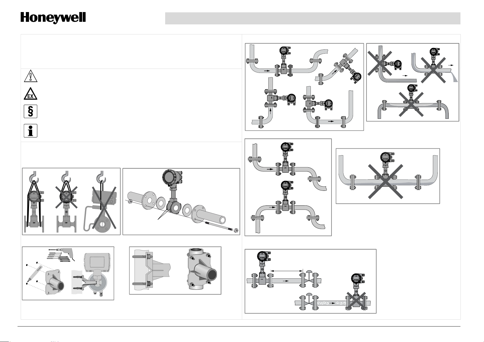
1 Installation
Transport
Sandwich design – centering rings
For initial set up, we strongly recommend the use of the relevant manuals in addition!
Steam & gases
Liquids
Centering rings
(part of scope of supply)
Remote: wall mounting of the field housing
Remote: pipe mounting of the field housing
Pipelines with control valve
5 DN
07/2019 - 4007779101 - 34-VF-25-76 iss.1 GLO July 2019 US
1
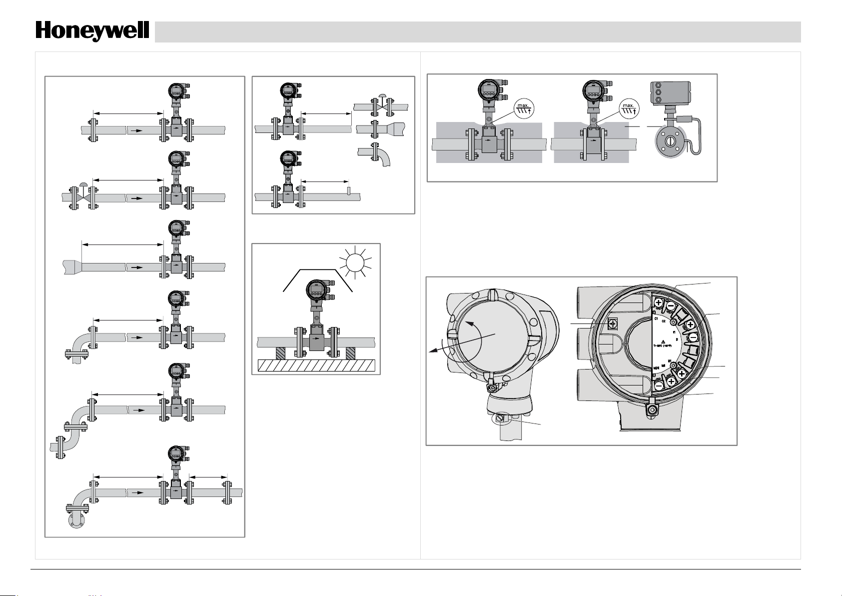
Minimum inlet section
15 DN
Minimum outlet section
5 DN
Heat insulation for T
> +160°C / +320°F
medium
1
1
50 DN
20 DN
20 DN
30 DN
Sunshade
5 DN
3
1 Marking of max. height of the insulation
2 Max. thickness of the insulation up to the bend of the pressure pipe
3 Insulation
2 Electrical connection
Connecting the signal converter
7
1
2
2
3
4
5
6
8
1 Open the housing cover of the electrical terminal compartment using the key
40 DN
07/2019 - 4007779101 - 34-VF-25-76 iss.1 GLO July 2019 US 2
> 5 DN
2 Signal converter supply and 4...20 mA loop
3 4...20 mA current input, - external transmitter, optional
4 Terminal M1 binary (high current)
5 Terminal M3 binary (NAMUR)
6 Terminal M2/4 binary, common minus connection
7 Ground terminal in housing
8 Ground terminal on connection piece between flow sensor and signal converter
 Loading...