

Honeywell VERSAFLOW MAG 1000 Quick Start Manual

Electromagnetic flow sensor
VERSAFLOW MAG 1000
VERSAFLOW MAG 1000VERSAFLOW MAG 1000
VERSAFLOW MAG 1000
Quick Start
Quick StartQuick Start
Quick Start
The documentation is only complete when used in combination with the relevant
documentation for the signal converter.

CONTENTS
2
www.honeywellprocess.com 34-VF-25-54 iss.3 GLO July 14 US
VERSAFLOW MAG 1000
1 Safety instructions 4
2 Installation 6
2.1 Scope of delivery............................................................................................................... 6
2.2 Device description ............................................................................................................ 7
2.3 Nameplate ........................................................................................................................ 8
2.4 Storage ............................................................................................................................. 9
2.5 Transport .......................................................................................................................... 9
2.6 Pre-installation requirements ......................................................................................... 9
2.7 General requirements .................................................................................................... 10
2.7.1 Vibration ................................................................................................................................ 10
2.7.2 Magnetic field........................................................................................................................ 10
2.8 Installation conditions ....................................................................................................11
2.8.1 Inlet and outlet...................................................................................................................... 11
2.8.2 Bends in 2 or 3 dimensions................................................................................................... 11
2.8.3 T-section ............................................................................................................................... 11
2.8.4 Bends .................................................................................................................................... 12
2.8.5 Open feed or discharge......................................................................................................... 12
2.8.6 Flange deviation.................................................................................................................... 13
2.8.7 Pump ..................................................................................................................................... 13
2.8.8 Control valve ......................................................................................................................... 13
2.8.9 Air venting and vacuum forces ............................................................................................. 14
2.8.10 Mounting position................................................................................................................ 15
2.9 Mounting......................................................................................................................... 15
2.9.1 Torques and pressures......................................................................................................... 15
2.10 Temperatures ............................................................................................................... 18
3 Electrical connections 20
3.1 Safety instructions.......................................................................................................... 20
3.2 Grounding ....................................................................................................................... 20
3.3 Virtual reference for TWM 9000 (C, W and F version).................................................... 22
3.4 Connection diagrams ..................................................................................................... 22
4 Technical data 24
4.1 Dimensions and weights ................................................................................................ 24
4.2 Vacuum load ................................................................................................................... 27
5 Technical data 29

CONTENTS
3
www.honeywellprocess.co34-VF-25-54 iss.3 GLO July 14 US
VERSAFLOW MAG 1000
1 SAFETY INSTRUCTIONS
4
VERSAFLOW MAG 1000
www.honeywellprocess.com 34-VF-25-54 iss.3 GLO July 14 US
Warnings and symbols used
HANDLING
• This symbol designates all instructions for actions to be carried out by the operator in the
specified sequence.
i RESULT
RESULTRESULT
RESULT
This symbol refers to all important consequences of the previous actions.
Safety instructions for the operator
DANGER!
This information refers to the immediate danger when working with electricity.
DANGER!
These warnings must be observed without fail. Even partial disregard of this warning can lead to
serious health problems and even death. There is also the risk of seriously damaging the device
or parts of the operator's plant.
WARNING!
Disregarding this safety warning, even if only in part, poses the risk of serious health problems.
There is also the risk of damaging the device or parts of the operator's plant.
CAUTION!
Disregarding these instructions can result in damage to the device or to parts of the operator's
plant.
INFORMATION!
These instructions contain important information for the handling of the device.
CAUTION!
Installation, assembly, start-up and maintenance may only be performed by appropriately
trained personnel. The regional occupational health and safety directives must always be
observed.
LEGAL NOTICE!
The responsibility as to the suitability and intended use of this device rests solely with the user.
The supplier assumes no responsibility in the event of improper use by the customer. Improper
installation and operation may lead to loss of warranty. In addition, the "Terms and Conditions of
Sale" apply which form the basis of the purchase contract.
INFORMATION!
•
Further information can be found on the supplied CD-ROM in the manual, on the data sheet,
in special manuals, certificates and on the manufacturer's website.
•
If you need to return the device to the manufacturer or supplier, please fill out the form
contained on the CD-ROM and send it with the device. Unfortunately, the manufacturer
cannot repair or inspect the device without the completed form.

SAFETY INSTRUCTIONS 1
5
VERSAFLOW MAG 1000
www.honeywellprocess.com34-VF-25-54 iss.3 GLO July 14 US
2 INSTALLATION
6
VERSAFLOW MAG 1000
www.honeywellprocess.com 34-VF-25-54 iss.3 GLO July 14 US
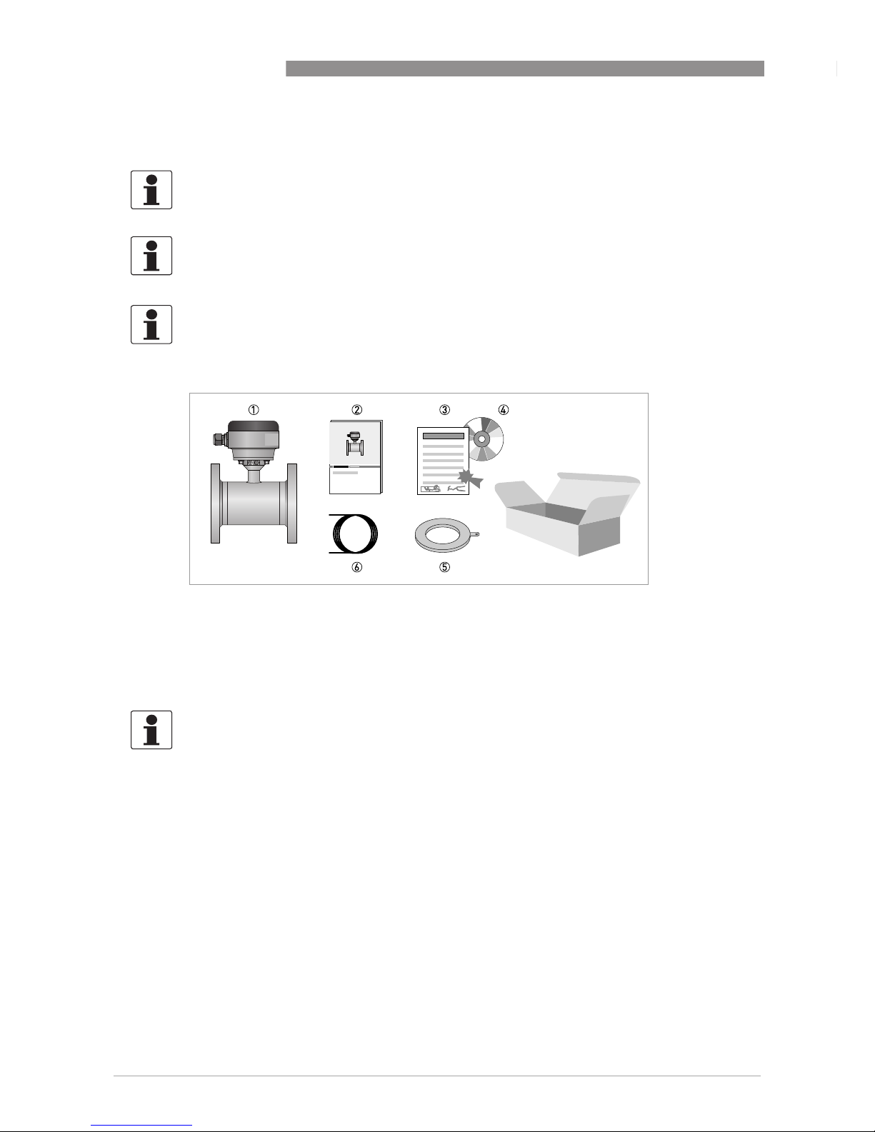
2.1 Scope of delivery
INFORMATION!
Do a check of the packing list to make sure that you have all the elements given in the order.
INFORMATION!
Inspect the packaging carefully for damages or signs of rough handling. Report damage to the
carrier and to the local office of the manufacturer.
INFORMATION!
The remote version will arrive in two cartons. One carton contains the converter and one carton
contains the sensor.
Figure 2-1: Scope of delivery
1 Ordered flowmeter
2 Product documentation
3 Factory calibration report
4 CD-ROM with product documentation in available languages
5 Grounding rings (optional)
6 Signal cable (remote versions only)
INFORMATION!
Assembly materials and tools are not part of the delivery. Use the assembly materials and tools
in compliance with the applicable occupational health and safety directives.
INSTALLATION 2
7
VERSAFLOW MAG 1000
www.honeywellprocess.com34-VF-25-54 iss.3 GLO July 14 US
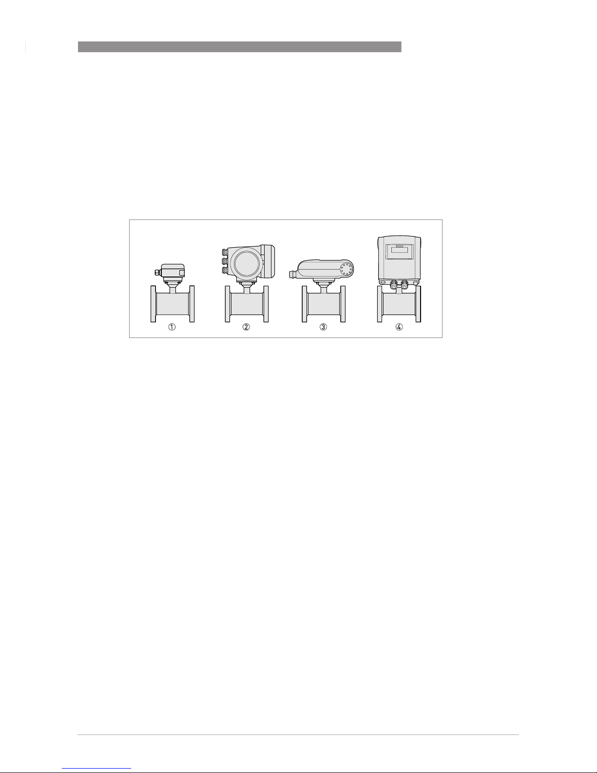
2.2 Device description
Your measuring device is supplied ready for operation. The factory settings for the operating
data have been made in accordance with your order specifications.
The following versions are available:
• Compact version (the signal converter is mounted directly on the measuring sensor)
• Remote version (a measuring sensor with connection box and a separate signal converter)
Figure 2-2: Device versions
1 Remote version
2 Compact version with TWM 9000 signal converter
3 Compact version with TWM 1000 (0°) signal converter
4 Compact version with TWM 1000 (45°) signal converter
2 INSTALLATION
8
VERSAFLOW MAG 1000
www.honeywellprocess.com 34-VF-25-54 iss.3 GLO July 14 US
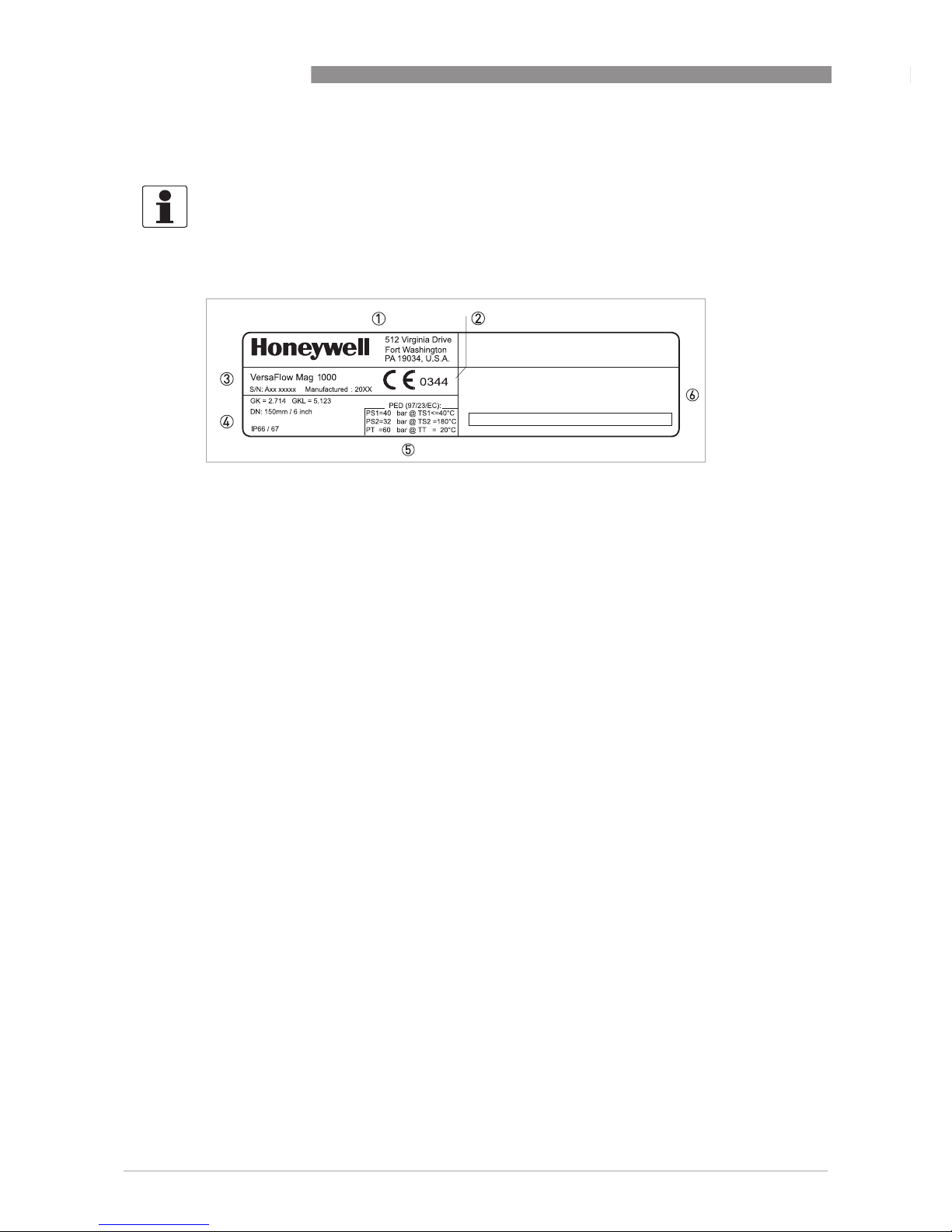
2.3 Nameplate
INFORMATION!
Check the device nameplate to ensure that the device is delivered according to your order.
Additional information (a.o correct supply voltage), can be found in the documentation of the
signal converter.
Figure 2-3: Example of nameplate
1 Name and address of the manufacturer
2 CE sign with number(s) of notified body / bodies
3 Type designation of the flowmeter and manufacturing date
4 Calibration data
5 PED data
6 Tag nr and approvals related information
INSTALLATION 2
9
VERSAFLOW MAG 1000
www.honeywellprocess.com34-VF-25-54 iss.3 GLO July 14 US
2.4 Storage
• Store the device in a dry and dust-free location.
• Avoid lasting direct exposure to the sun.
• Store the device in its original packaging.
• Storage temperature: -50 ...+70°C / -58...+158°F
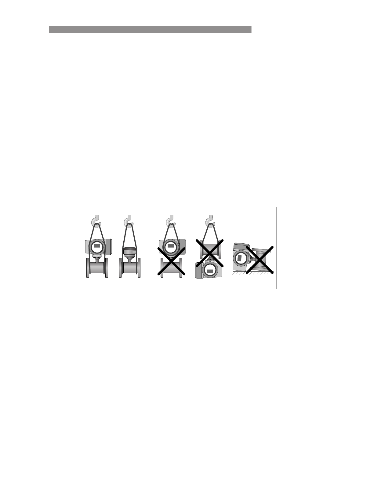
2.5 Transport
Signal converter
• No special requirements.
Compact version
• Do not lift the device by the signal converter housing.
• Do not use lifting chains.
• To transport flange devices, use lifting straps. Wrap these around both process connections.
2.6 Pre-installation requirements
Make sure that you have all necessary tools available:
• Allen key (4 mm)
• Small screwdriver
• Wrench for cable glands
• Wrench for wall mounting bracket (remote version only)
• Torque wrench for installing flowmeter in pipeline
Figure 2-4: Transport
 Loading...