

Page 1

Verifier Integration Interface
For PX940V Printer
Command Reference
Page 2

Disclaimer
Honeywell International Inc. (“HII”) reserves the right to make changes in specifications and other information contained in
this document without prior notice, and the reader should in all cases consult HII to determine whether any such changes
have been made. The information in this publication does not represent a commitment on the part of HII.
HII shall not be liable for technical or editorial errors or omissions contained herein; nor for incidental or consequential
damages resulting from the furnishing, performance, or use of this material. HII disclaims all responsibility for the selection and use of software and/or hardware to achieve intended results.
This document contains proprietary information that is protected by copyright. All rights are reserved. No part of this document may be photocopied, reproduced, or translated into another language without the prior written consent of HII.
Copyright 2020 Honeywell International Inc. All rights reserved.
Web Address:
www.honeywellaidc.com
Patents
For patent information, refer to www.hsmpats.com.
Page 3

TABLE OF CONTENTS
Customer Support ....................................................................................................................... vii
Technical Assistance ............................................................................................................ vii
Product Service and Repair ............................................................................................... vii
Limited Warranty ................................................................................................................... vii
Chapter 1 - Get Started ....................................................................................1
Features ............................................................................................................................................. 1
About this Manual.......................................................................................................................... 1
Interface Diagram ..........................................................................................................................2
Data Protocol ................................................................................................................................... 2
Network Interface...........................................................................................................................2
Chapter 2 - Printer and Host PC Setup.........................................................3
Set Up Printer................................................................................................................................... 3
Access the Printer Web Page............................................................................................... 3
Configure VII.............................................................................................................................. 3
Execution Mode................................................................................................................. 5
Verifier Mode.......................................................................................................................5
Command Channel, Feedback Channel, and Image Channel........................6
Set Up Host PC................................................................................................................................6
Command Channel.................................................................................................................7
Configure Command Channel.....................................................................................7
Feedback Channel................................................................................................................... 7
Configuring Feedback Channel .................................................................................. 8
Image Channel.......................................................................................................................... 8
VII Command Reference iii
Page 4

Configuring Image Channel..........................................................................................8
Chapter 3 - Commands and Responses ........................................................9
Commands ........................................................................................................................................9
Response.........................................................................................................................................10
GetPrinterInfo ...............................................................................................................................11
CancelAllJobs................................................................................................................................12
GetLabelImage .............................................................................................................................13
GetPrinterStatus ..........................................................................................................................14
ImageTransfer...............................................................................................................................15
PausePrintJob...............................................................................................................................16
PrinterError ....................................................................................................................................17
PrintJobStatus..............................................................................................................................18
ReprintPrintJob ............................................................................................................................ 19
ResetVerificationResult.............................................................................................................20
ResumePrintJob...........................................................................................................................21
RetractLabel ..................................................................................................................................22
ReverifyLabel.................................................................................................................................23
SendVerificationResult.............................................................................................................. 24
SetCommandChannelPort.......................................................................................................25
SetExecutionMode......................................................................................................................26
SetFeedbackChannelPort ........................................................................................................27
SetImageChannelPort ...............................................................................................................28
SetVerifierMode............................................................................................................................ 29
VerificationResult ........................................................................................................................30
VoidLabel ........................................................................................................................................31
Error Codes.....................................................................................................................................32
Chapter 4 - Troubleshooting........................................................................ 33
Problems and Possible Solutions..........................................................................................33
Chapter 5 - Use Case Sequence Diagram .................................................. 35
Printer Error ...................................................................................................................................35
iv VII Command Reference
Page 5

Print Job - Pause, Resume, Cancel .......................................................................................36
Appendix A - Verification Report .................................................................37
Sample Verification Report ......................................................................................................37
VII Command Reference v
Page 6

vi VII Command Reference
Page 7

Customer Support
Technical Assistance
To search our knowledge base for a solution or to log in to the Technical Support
portal and report a problem, go to www.hsmcontactsupport.com.
For our latest contact information, see www.honeywellaidc.com/locations.
Product Service and Repair
Honeywell International Inc. provides service for all of its products through service
centers throughout the world. To obtain warranty or non-warranty service, return
your product to Honeywell (postage paid) with a copy of the dated purchase record.
To learn more, go to www.honeywellaidc.com and select Service and Repair at the
bottom of the page.
Limited Warranty
For warranty information, go to www.honeywellaidc.com and click Get Resources >
Product Warranty.
VII Command Reference vii
Page 8

viii VII Command Reference
Page 9

CHAPTER
1
GET STARTED
The PX940V is a rugged label printer with ANSI Grade (ISO15415/15416)
verification for label printing.
The Verifier Integration Interface of the PX940V printer allows you to communicate
with the printer through a host PC setup. Using the Verifier Integration Interface
(VII), verification data can be collected as images and XML reports.
A TCP/IP connection needs to be configured between the printer and host PC for
communication.
Features
The verifier identifies and verifies the printed barcode using supported command
languages.
The VII can be used for the following:
• Label validation
• Secondary Grading
• Grading Barcodes
• Storing Audit Trails
• Label Duplication Detection
• Label Serialization Detection
About this Manual
This command reference provides you information about the interface between the
printer with the verifier and a host PC and a set of commands to help you create
applications for the PX940V Printer.
The following abbreviations are used in this guide:
• VII - Verifier Integration Interface
VII Command Reference 1
Page 10
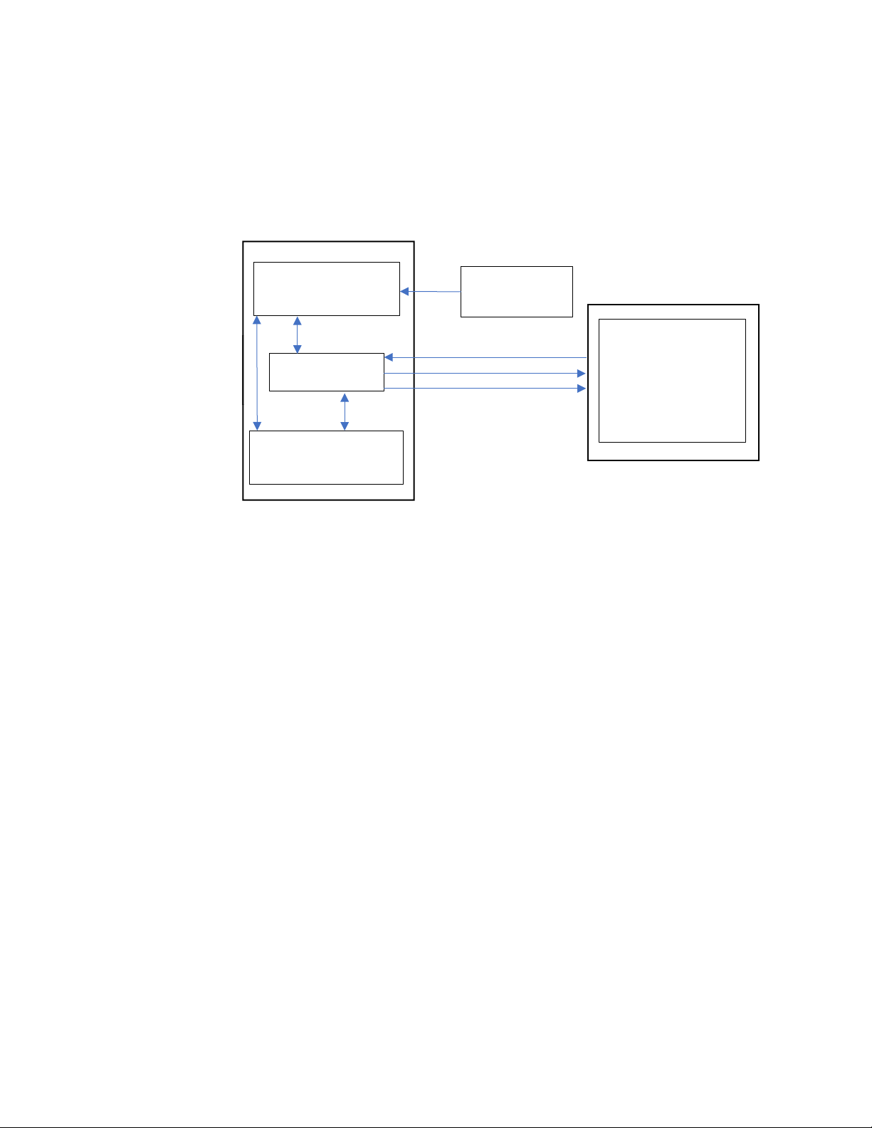
• TPH - Thermal PrintHead
(ANSI GRADING)
Printing
VII
Printjob
DAEMON PROCESS
VII DAEMON
PROCESS
Interface Diagram
The interface between the VII and the host PC is illustrated below:
SYNC
Verification
PRINTER
HOST PC
Feedback
Command Channel
Image Channel
Feedback Channel
Image/Result
:
Data Protocol
XML is the data format set for the host PC to communicate with Verifier Integration
Interface.
Network Interface
A TCP/IP network interface is set up for the host PC to access the printer.
Note: While one host can be connected to multiple printers, each printer can only be
connected to a single host at a time.
2 VII Command Reference
Page 11

CHAPTER
PRINTER AND HOST PC SETUP
2
This chapter provides details to set up communication between VII and Host PC.
Set Up Printer
User can set up the printer through a web page or the printer LCD.
Access the Printer Web Page
1. Open a browser window on your PC.
2. In the location or address bar, type the printer IP address and press Enter.
3. Click Login. The login page appears.
You will be prompted to enter a username and password. The defaults are:
After logging In, you will be prompted to change the password.
Configure VII
Before being able to configure the verifier integration interface service, it must be
enabled in the Manage service configuration.
To enable the verifier integration interface service through the web page, click
Configure > System Settings > Manage Services.
or
Through the front touch panel.
• User Name: itadmin
• Password: pass
VII Command Reference 3
Page 12
Once the VII is enabled in the Manage services section, you can configure VII in
detail through the web page.
Click Configure > Network Services > VII.
or
Through the front touch panel.
The options for the VII are as follows:
• Execution Mode
• Verifier Mode
• Command Channel
• Image Channel
• Feedback Channel
4 VII Command Reference
Page 13
Execution Mode
The Execution Mode allows you to control the synchronization between label
printing and printed label capture and verification.
Asynchronous Mode
One label is inspected while the next label is being printed and/or having its image
scanned.
Synchronous Mode
A single label is printed, image scanned and fully inspected before any other labels
are printed.
The default value is Asynchronous.
Verifier Mode
The verification modes define the types of the verification process.
For the VII, there are three types of verification modes:
1. Mode1 - Scan
2. Mode2 - Scan and grade
3. Mode3 - Scan, grade and control
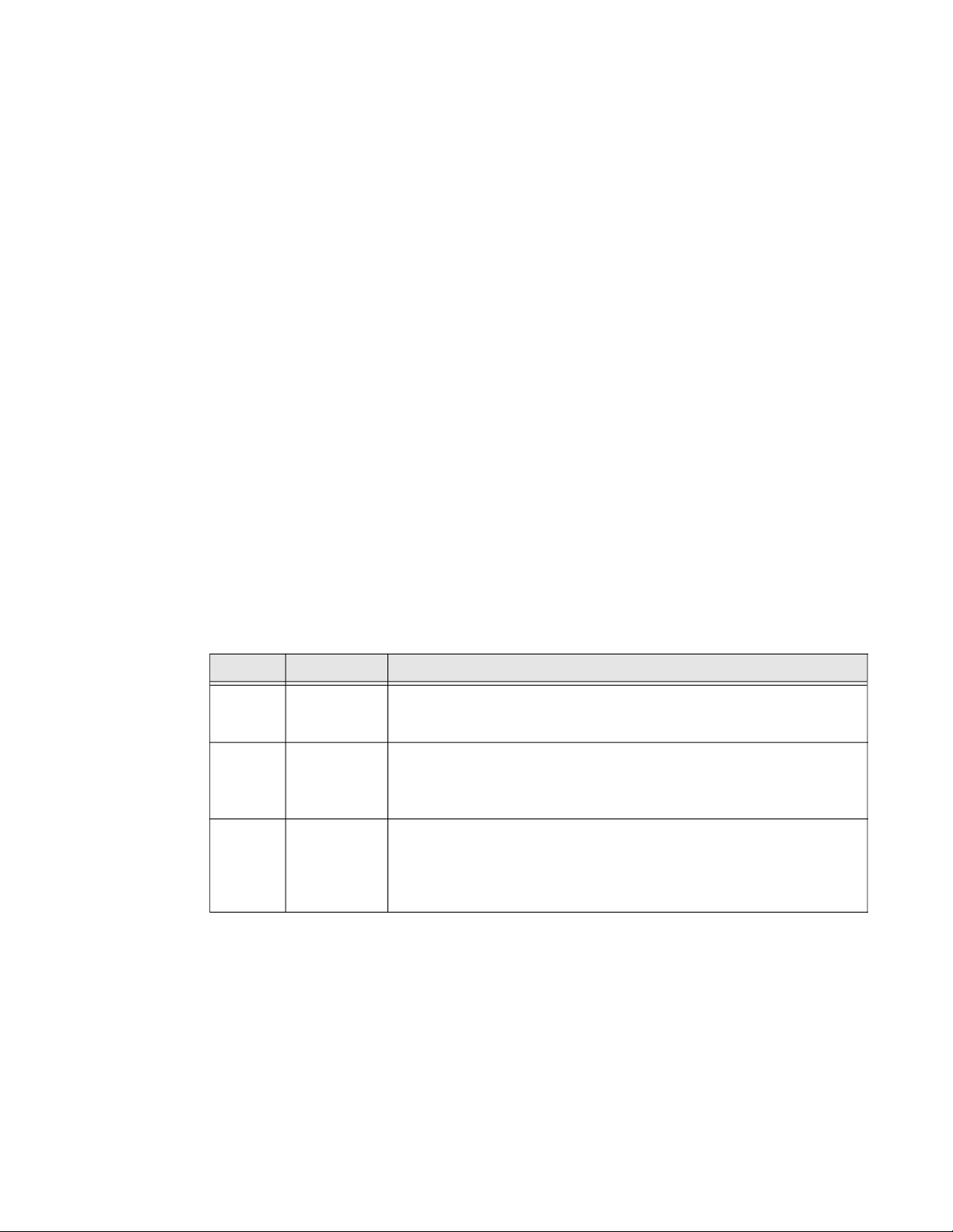
Verifier Modes and Description
Modes Operation Description
Mode1 Scan The verifier will only scan the printed image, it will not do barcode
inspection. The host retrieves the image, analyzes it and control the
printer action.
Mode2 Scan and
grade
Mode3 Scan, grade
and control
The verifier will inspect the barcode. The host controls the printer action
and could also analyze the image. If the image channel is enabled from
host, the label image will be sent to host, otherwise the label image will
not be sent to host.
The verifier inspect barcode and do failure action handling. The host
captures reports and images for storage. The barcode verification result
will be sent to host via feedback channel. If image channel is enabled
from host, the label image will be sent to host, otherwise the label image
will not be sent to host.
For verifier modes 1 and 2, the printer will wait for the verification result from host.
In Synchronous Mode on page 5, if printer does not receive verification result from
host, printer will stop after printing 1 label.
In Asynchronous Mode on page 5, printer will stop after printing X number of labels
depending on the label length as indicated in the table below.
VII Command Reference 5
Page 14
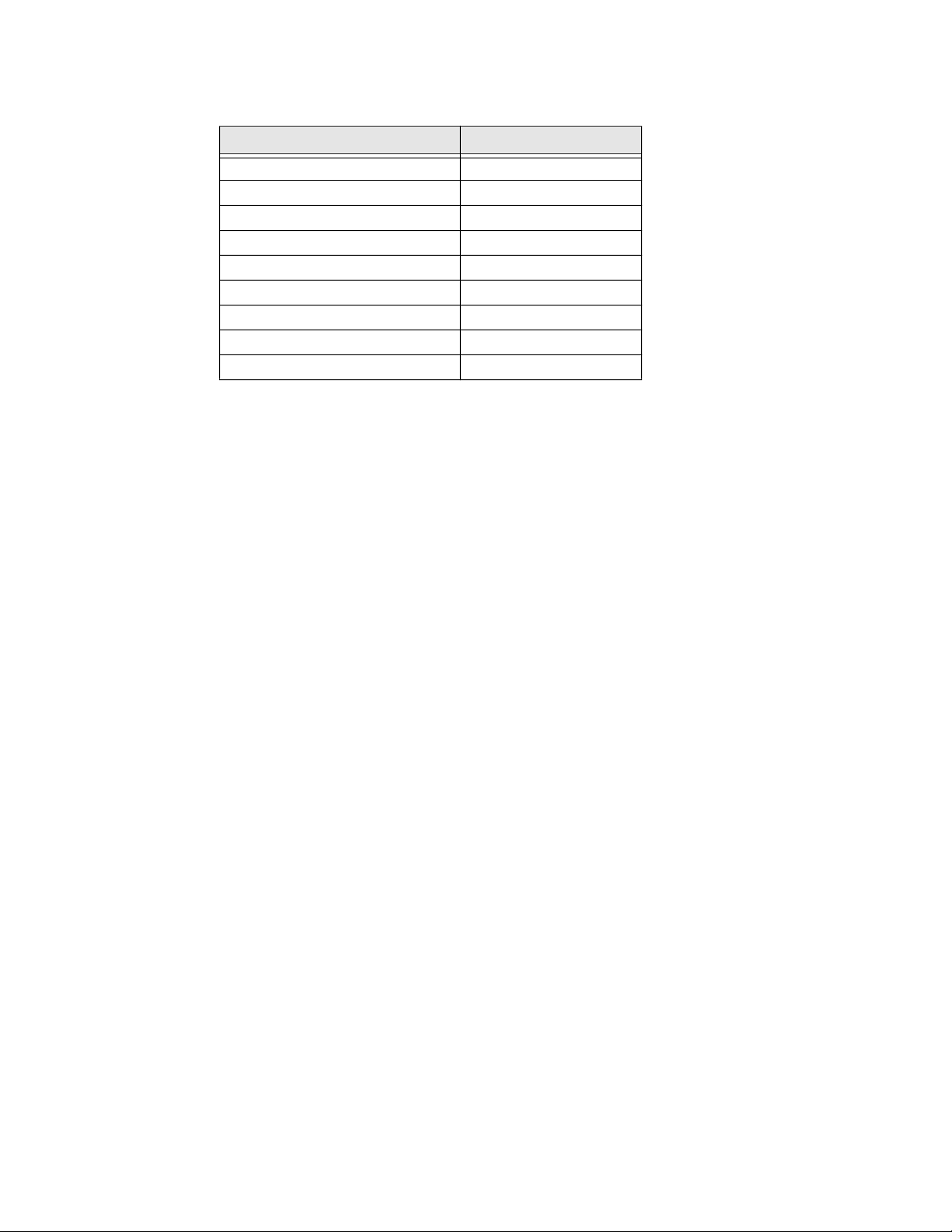
Label number and Label Length range
Label Length Range (inches) Number of labels (X)
> 4.00 3
> 0.68 4
> 0.52 5
> 0.41 6
> 0.35 7
> 0.30 8
> 0.26 9
> 0.24 10
> 0.00 11
Command Channel, Feedback Channel, and Image Channel
Defines the port used for the host to connect to the printer. The range of the port
number is 9301 - 65535.
Note: Your firewall must be configured to allow these ports to be accessible otherwise a
failure may occur.
All the three communication channels must be opened to send or receive any data
from the printer. For example, if the image channel is closed, the printer cannot
send raw image data to the host.
Set Up Host PC
Verifier Integration interface allows you to transfer data between printer and host
and control the printer from the host.
The host PC communicates with the printer using certain commands. To send the
commands, user has to set up the communication channel and configure
accordingly.
The communication channels are,
• Command Channel
• Feedback Channel
• Image Channel
Command Channel
The command channel is used to issue commands from host to printer. The
commands can be sent based on the feedback result received from the printer to
host or to get printing information.
6 VII Command Reference
Page 15
There are four types of commands that can be sent through command channel,
namely,
• Query Information Command
• Configuration Command
• Printing Control Command
• Update Command
The types of commands that can be sent through the command channel from the
host PC to the printer are detailed here.
Query
Information
command
GetPrinterInfo
GetPrinterStatus
GetLabelImage
Configure Command Channel
Setup a TCP/IP connection between host PC and printer to open the command
channel.
Command channel need to be connected before connecting Feedback channel.
The Feedback channel will only accept connection from Command channel's Host
(same IP), else, even if it shows connection OK, there won't be any output from this
channel.
Configuration
command
SetExecutionMode CancelAllJobs SendVerificationResult
SetVerifierMode PausePrintJob
SetCommandChannelPort ResumePrintJob
SetFeedbackChannelPort ReprintPrintJob
SetImageChannelPort VoidLabel
ResetVerificationResult RetractLabel
Printing
control
command
ReverifyLabel
Update command
Feedback Channel
The feedback channel is used by the printer to send the print job status, verification
result, or error result to host. These are sent by the printer automatically.
The responses from the feedback channel are:
• PrintJobStatus
• VerificationResult
• PrinterError
Configuring Feedback Channel
Setup a TCP/IP connection between the host PC and printer to open the feedback
channel.
VII Command Reference 7
Page 16

The command channel must be open before the feedback channel as both the
channel share the same IP address.
Note: Command channel need to be connected before connecting Feedback channel,
Feedback channel will only accept connections from Command channel's Host
(same IP).
Image Channel
The image channel is used to send the label images from printer to host. The
images can be BMP or raw image data. The image data is automatically sent from
the printer without any request from the host.
The responses for the image channel are,
• ImageTransfer
Configuring Image Channel
Setup a TCP/IP connection between the host PC and printer to open the image
channel.
The Image channel must be configured if the host PC expects to receive raw image
data from the printer. If the raw image data is not needed, then the image channel
need not be configured.
8 VII Command Reference
Page 17

CHAPTER
3
This chapter provides details about the Commands and Responses of all the
functionality of the verifier integration interface.
Commands
COMMANDS AND RESPONSES
Command Name Purpose
GetPrinterInfo Returns the printer information such as printer serial number, printer
model etc.
CancelAllJobs To instruct the printer to cancel all the pending print jobs.
GetLabelImage Returns label image based on label ID.
GetPrinterStatus Returns the printer status such as busy or available.
PausePrintJob To instruct the printer to stop printing.
ReprintPrintJob To instruct the printer to reprint the label specified by the host.
ResetVerificationResult To reset the verification result database stored in printer.
ResumePrintJob To instruct printer to resume from a printer pause mode.
RetractLabel To instruct printer to retract the label specified by the host using Label ID.
PausePrintJob To instruct the printer to stop printing.
ReprintPrintJob To instruct the printer to reprint the label specified by the host.
ResetVerificationResult To reset the verification result database stored in printer.
VII Command Reference 9
Page 18

Response
The feedback channel and image channel returns response automatically without any request from
host.
Command Name Purpose
ImageTransfer To send label image from the printer to host.
PrinterError To send the printer error information to host.
PrintJobStatus To send print job status from the printer to host.
VerificationResult To send Barcode verification result from the printer to the host.
10 VII Command Reference
Page 19

GetPrinterInfo
This command returns printer information such as printer serial number, printer
model etc.
XML Request
<VII Action=“GetPrinterInfo”>
</VII>
XML Response
<VII Action="GetPrinterInfo" Status="00">
<PrinterName>[printer name]</PrinterName>
<ModelName>[model name]</ModelName>
<SerialNumber>[serial number]</SerialNumber>
<VerifierResolution>[resolution]</VerifierResolution>
</VII>
Parameter
Elements Description
PrinterName
ModeName
SerialNumber
VerifierResolution
In case of error, the XML response will be,
<VII Action="GetPrinterInfo" Status=[error code]>
</VII>
For error codes, refer to Error Codes.
Name of the printer
Model name of the printer
Serial number of the printer
Verifier resolution of the printer.
The resolution is in dpi unit,
for example <VerifierResolution>600</VerifierResolution>
VII Command Reference 11
Page 20

CancelAllJobs
This command instructs the printer to cancel all pending print jobs.
XML Request
<VII Action="CancelAllJobs">
</VII>
XML Response
<VII Action="CancelAllJobs" Status="00">
</VII>
In case of error, the XML response will be,
<VII Action="CancelAllJobs" Status=[error code]>
</VII>
For error codes, refer to Error Codes.
12 VII Command Reference
Page 21

GetLabelImage
This command retrieves the label image based on the specified label ID.
XML Request
<VII Action="GetLabelImage">
<LabelID>[label ID]</LabelID>
</VII>
Elements Description
LabelID
XML Response
In case of successful command execution, the specified label image will be sent to
host via command channel.
<VII Action="GetLabelImage" Status="00" Type="BMP" ID="1"
Size="XYZ">
<Image>[Data Block]</Image>
</VII>
Unique identifier for the labels.
LabelID can be retrieved from PrintJobStatus, and
VerificationResult responses. The LabelID must be the LabelID
reported back in the last response by feedback channel.
Parameters
In case of error, the XML response will be,
<VII Action="GetLabelImage" Status=[error code]>
</VII>
For error codes, refer to Error Codes.
Name Description
Type
ID
Size
Data Block
Label image in BMP format
Label ID for each label
Data size of actual image
BMP data including BMP header
VII Command Reference 13
Page 22

GetPrinterStatus
This command is to check current printer status. It will help to check if the printer is
busy or available.
For all supported status, see “Error Codes section under Fingerprint Command
Reference Manual”.
XML Request
<VII Action="GetPrinterStatus">
</VII>
XML Response
<VII Action="GetPrinterStatus" Status="00">
<PrinterStatus>[status message]</PrinterStatus>
</VII>
Parameter
Elements Description
PrinterStatus Printer status message.
Status message does not support localization.
The status messages can be,
• Busy
• Available
• Out of media
• Printhead lifted
• Front arm lifted
• Out of ribbon
• Label not found
• Test feed not done
• Ribbon installed
• Printhead too hot
• Remove Label
In case of error, “GetPrinterStatus” XML response will be as listed below:
<VII Action="GetPrinterStatus" Status=[error code]>
</VII>
For error codes, refer to Error Codes.
14 VII Command Reference
Page 23

ImageTransfer
This is the response to send label image from printer to host.
XML Format
The XML format of image data transferred via image channel.
<VII Action="ImageTransfer" Type="RAW" ID="1" Width="XYZ">
<Image>[Data Block]</Image>
</VII>
Parameter
Name Description
Type
ID
Width
Data Block
Label image in raw format
Label ID for each label
Width of image data block
Raw image data block
VII Command Reference 15
Page 24

PausePrintJob
This command is to instruct the printer to pause from printing.
XML Request
<VII Action="PausePrintJob">
</VII>
XML Response
<VII Action="PausePrintJob" Status="00">
</VII>
In case of error, 'PausePrintJob' XML response will be,
<VII Action="PausePrintJob" Status=[error code]>
</VII>
For error codes, refer to Error Codes.
16 VII Command Reference
Page 25

PrinterError
This is the response to feedback any printer error, for example “Out of media”.
This is automatically sent from printer to host.
XML Response
<VII Action="PrinterError">
<PrinterError>[printer error]</PrinterError>
</VII>
Printer error can be as Follows:
• Printhead lifted
• Front arm lifted
• Next label not found
• Out of media
• Out of ribbon
• Ribbon installed
Note: For use case sequence diagram, refer to Printer Error.
VII Command Reference 17
Page 26

PrintJobStatus
This is a response to feedback print job status from printer to host. After each label
is printed, the label printing status will be sent to host.
XML Response
<VII Action="PrintJobStatus">
<LabelID>[label ID]</LabelID>
<PrintJobStatus>[print job status]</PrintJobStatus>
</VII>
Print job status can be “Printed” or “Printing Failed”.
18 VII Command Reference
Page 27

ReprintPrintJob
This command is to instruct printer to reprint the label specified by host. The label
can be specified by the label ID and option.
XML Request
<VII Action="ReprintPrintJob">
<LabelID>[label ID]</LabelID>
<Option>[option]</Option>
</VII>
Print job option should be either “Single” or “All”.
If option is “Single”, only the label specified by label ID will be reprinted.
If option is “All”, then the labels between the label specified by label ID and the last
printed label will be reprinted.
The reprint range will be from 3 to 11 which decrease when media length is
changing from small to big. Refer to Label number and Label Length range on
page 6.
For example, if the number of label is 3 and last label ID sent back to host is 5, the
host only can send back the label ID for reprint from 3 to 5.
XML Response
<VII Action="ReprintPrintJob" Status="00">
</VII>
In case of error, 'ReprintPrintJob' XML response will be as listed below:
<VII Action="ReprintPrintJob" Status=[error code]>
</VII>
For error codes, refer to Error Codes.
VII Command Reference 19
Page 28

ResetVerificationResult
This command is to reset verification result database stored in printer.
XML Request
<VII Action="ResetVerificationResult">
</VII>
XML Response
<VII Action="ResetVerificationResult" Status="00">
</VII>
In case of error, “ResetVerificationResult" XML response will be as listed below:
<VII Action="ResetVerificationResult" Status=[error code]>
</VII>
For error codes, refer to Error Codes.
20 VII Command Reference
Page 29

ResumePrintJob
This command is to instruct printer to resume printing from a printer pause mode.
XML Request
<VII Action="ResumePrintJob">
</VII>
XML Response
<VII Action="ResumePrintJob" Status="00">
</VII>
In case of error, “ResumePrintJob” XML response will be as listed below:
<VII Action="ResumePrintJob" Status=[error code]>
</VII>
For error codes, refer to Error Codes.
VII Command Reference 21
Page 30

RetractLabel
This command is to instruct the printer to retract the label specified by host using
label ID.
XML Request
<VII Action="RetractLabel">
<LabelID>[label ID]</LabelID>
</VII>
The range of how many labels can be retracted is between 3 and 11 which decrease
when media length is changing from small to big. Refer to Label number and Label
Length range on page 6.
For example, if the number of label is 3 and last label ID sent back to host is 5, the
host only can send back the label ID for retract from 3 to 5.
XML Response
<VII Action="RetractLabel " Status="00">
</VII>
In case of error, “RetractLabel ” XML response will be as listed below:
<VII Action="RetractLabel " Status=[error code]>
</VII>
For error codes, refer to Error Codes.
22 VII Command Reference
Page 31

ReverifyLabel
This command is to instruct printer to re-verify a single label specified by the
LabelID.
Note: When a label has been retracted through the TPH, the original grade (first time
verified) may not be accurate anymore. This command lets you regrade the label
again.
XML Request
<VII Action="ReverifyLabel">
<LabelID>[label ID]</LabelID>
</VII>
The range of how many labels can be reverified is from 3 to 11 which decrease
when media length is changing from small to big. Refer to Label number and Label
Length range on page 6.
For example, if the number of label is 3 and last label ID sent back to host is 5, the
host only can send back the label ID for reverify from 3 to 5.
XML Response
<VII Action="ReverifyLabel " Status="00">
</VII>
In case of error, “ReverifyLabel ” XML response will be as shown below:
<VII Action="ReverifyLabel " Status=[error code]>
</VII>
This response reply the status of reverify action. The verification result will be same
as normal printing verification sent from feedback channel.
For error codes, refer to Error Codes.
VII Command Reference 23
Page 32

SendVerificationResult
This command is to send barcode/image verification result from the host to the
printer.
In Synchronous Mode on page 5, printer will stop subsequent label printing and
wait for verification result from host. In Asynchronous Mode on page 5, printer will
stop print after all image buffer is used up.
Note: The SendVerificationResult is for verification modes 1 and 2 only.
XML Request
<VII Action="SendVerificationResult">
<LabelID>[label ID]</LabelID>
<VerificationResult>[verification result]</
VerificationResult>
</VII>
Verification result can be “Pass” or “Fail”.
XML Response
<VII Action="SendVerificationResult" Status="00">
</VII>
In case of error, “SendVerificationResult” XML response will be as listed below:
<VII Action="SendVerificationResult" Status=[error code]>
</VII>
For error codes, refer to Error Codes.
24 VII Command Reference
Page 33

SetCommandChannelPort
This command is to set the port number of the command channel. The default
value is “9301”. The range of the port numbers are 9301 - 65535.
XML Request
<VII Action="SetCommandChannelPort">
<PortNumber>[port number]</PortNumber>
</VII>
XML Response
In case of successful command execution, no response will be sent, as port will be
reset to new value.
In case of error, 'SetCommandChannelPort' XML response will be as listed below:
<VII Action="SetCommandChannelPort" Status=[error code]>
</VII>
Note: User can reconnect to a new port from the range 9301-65535.
For error codes, refer to Error Codes.
VII Command Reference 25
Page 34

SetExecutionMode
For Execution Mode, Refer to Execution Mode on page 5.
XML Request
<VII Action="SetExecutionMode">
<Option>[option]</Option>
</VII>
XML Response
<VII Action="SetExecutionMode" Status="00">
</VII>
In case of error, 'SetExecutionMode' XML response will be as listed below:
<VII Action="SetExecutionMode" Status=[error code]>
</VII>
For error codes, refer to Error Codes.
26 VII Command Reference
Page 35

SetFeedbackChannelPort
This command is to set the port number of the feedback channel. The default value
is "9302". The range of the port numbers are 9301 - 65535.
Note: Command port need to be connected before connecting Feedback channel. The
Feedback channel will only accept connection from Command channel's Host (same
IP), else, even if it shows connection OK, there won't be any output from this channel.
XML Request
<VII Action="SetFeedbackChannelPort">
<PortNumber>[port number]</PortNumber>
</VII>
XML Response
In case of successful command execution, no response will be sent as port will be
reset to new value.
In case of error, “SetFeedbackChannelPort” XML response will be as listed below:
<VII Action="SetFeedbackChannelPort" Status=[error code]>
</VII>
Note: User can reconnect to a new port from the range 9301-65535.
For error codes, refer to Error Codes.
VII Command Reference 27
Page 36

SetImageChannelPort
This command is to set the port number of the image channel. The default value is
"9303". The range of the port numbers are 9301 - 65535.
Note: Command port need to be connected before connecting the image channel. The
image channel will only accept connection from the same host (same IP) connected
by the command channel, else, even if it shows connection OK, there won't be any
output from this channel.
XML Request
<VII Action="SetImageChannelPort">
<PortNumber>[port number]</PortNumber>
</VII>
XML Response
In case of successful command execution, no response will be sent, as port will be
reset to new value.
In case of error, 'SetImageChannelPort" XML response will be as listed below:
<VII Action="SetImageChannelPort" Status=[error code]>
</VII>
Note: User can reconnect to a new port from the range 9301-65535.
For error code, refer to Error Codes.
28 VII Command Reference
Page 37

SetVerifierMode
This command is to set verifier mode.
XML Request
<VII Action="SetVerifierMode">
<Option>[option]</Option>
</VII>
Verifier option can be below value:
1. Scan
2. Scan and grade
3. Scan, grade and control
Note: The default value is "3".
XML Response
In case of successful command execution, 'SetVerifierMode' XML response will be
as listed below:
<VII Action="SetVerifierMode" Status="00">
</VII>
In case of error, “SetVerifierMode” XML response will be as shown below:
<VII Action="SetVerifierMode" Status=[error code]>
</VII>
For error codes, refer to Error Codes.
S
VII Command Reference 29
Page 38

VerificationResult
This is the response to feedback barcode verification result from printer to host. If
the barcode inspection is performed by printer verifier, the verification result will
be sent to host after each label is inspected.
Note: The verification mode applicable are mode 2 and 3.
XML Response
<VII Action="VerificationResult">
<LabelID>[label ID]</LabelID>
<VerificationResult>[verification result]</
VerificationResult>
<VerificationReport>[verification report]</
VerificationReport>
</VII>
Verification result can be "Pass" or "Fail".
The verification report will be XML format, and use UTF-8 as character encoding.
For a sample of verification report, refer to Appendix A.
30 VII Command Reference
Page 39

VoidLabel
This command is to instruct printer to mark up VOID on printed label.
XML Request
</VII>
VoildLabel option should be either "Single" or "All".
If option is "Single", only the label specified by label ID will be VOID.
If option is "All", then the labels between the label specified by label ID and the last
printed label will be VOID.
The range of how many labels can be VOID will be based on the Label number and
Label Length range on page 6.
For example, if the number of label is 3 and last label ID sent back to host is 5, the
host only can send back the label ID for voiding from 3 to 5.
<VII Action="VoidLabel">
<LabelID>[label ID]</LabelID>
<Option>[option]</Option>
XML Response
In case of successful command execution, 'VoidLabel ' XML response will be as
listed below:
<VII Action="VoidLabel " Status="00">
</VII>
In case of error, 'VoidLabel ' XML response will be as listed below:
<VII Action="VoidLabel " Status=[error code]>
</VII>
For error codes, refer to Error Codes.
VII Command Reference 31
Page 40

Error Codes
The following table details the possible causes or error and its description.
Error Codes Command Possible Cause Description
00 NA NA Command status is OK
01 NA Invalid XML Wrong syntax for the respective XML
02 NA Label ID Not Found The specified label ID cannot be found in
03 NA Command Error Error in command handling
04 NA Unknown Error Invalid command/other errors
commands used
printer
32 VII Command Reference
Page 41

CHAPTER
TROUBLESHOOTING
4
Problems and Possible Solutions
Problems Possible Solution
The Ethernet or wireless
network connection is not working
correctly
Printing stops May happen on VII mode 1/2 due to missing command from
Printer does not print label in batch
mode for batch printing
Missing result/Image files Try these possible solutions:
Printer is not voiding the full label Try these possible solutions:
Try these possible solutions:
• Make sure your network cable is securely connected to
your printer and is straight pin-to-pin cable, not a
crossover cable.
• Make sure your PC is correctly configured for and
connected to your network.
• Make sure your printer is correctly configured for your
network.
Host to printer. Drop the current connection and force the
printer to discard its current state.
Try these possible solutions:
• Lower the printing speed.
• Reduce the network route (move the printer and host pc
to the same network).
• Use Ethernet connection instead of Wireless
connection.
• Reset Verification result by UI/Webpage/VII command.
• Lower the printing speed.
• Reduce the network route (move the printer and host pc
to the same network).
• Use Ethernet connection instead of Wireless
connection.
• Change the Host application implementation dedicated
process/thread for receiving data rather than using the
same thread/process for receiving and data handling.
• Set the correct void length in printer setting
• Adjust the TPH pressure to avoid media slipping.
VII Command Reference 33
Page 42

Problems Possible Solution
Not able to connect to printer Try these possible solutions:
• Check network status, and make sure your host PC is
able to ping the printer IP address.
• Check your printer setting, and make sure your printer
VII service is enabled.
• Check your printer setting, and make sure the expected
VII ports are used.
• Printer might be connected to another Host PC,
disconnect the current connection.
• Check your Host PC port, and make sure VII ports are
not being used by other processes.
• Check your firewall setting, make sure VII ports are not
blocked by firewall.
Image data is not received • Try these possible solutions:
• Check network status, and make sure your host PC is
able to ping the printer IP address
• Check your printer setting, and make sure your printer
VII service is enabled.
• Check your printer setting, and make sure the expected
VII ports are used.
• Printer might be connected to another Host PC,
disconnect the current connection.
• Check your Host PC port, and make sure VII ports are
not being used by other processes.
• Check your firewall setting, make sure VII ports are not
blocked by firewall.
Report data is not received Try these possible solutions:
• Check network status, and make sure your host PC is
able to ping the printer IP address.
• Check your printer setting, and make sure your printer
VII service is enabled.
• Check your printer setting, and make sure the expected
VII ports are used.
• Printer might be connected to another Host PC,
disconnect the current connection.
• Check your Host PC port, and make sure VII ports are
not being used by other processes.
• Check your firewall setting, make sure VII ports are not
blocked by firewall.
Image data is not received in real
time
Try these possible solutions:
• Reduce print speed
• Reduce traffic congestion on network
34 VII Command Reference
Page 43

CHAPTER
USE CASE SEQUENCE DIAGRAM
5
Printer Error
The use case show when printer error happen before/during printing.
VII Command Reference 35
Page 44

Print Job - Pause, Resume, Cancel
This use case displays the host request to Pause/Print/Cancel print job.
Note: The pause will be executed on the next label.
36 VII Command Reference
Page 45

APPENDIX
VERIFICATION REPORT
A
Sample Verification Report
<Label ID="4">
<PrintJobID>4</PrintJobID>
<VerificationType>ISO 15415/15416</VerificationType>
<PassingGrade>1.5 (C)</PassingGrade>
<HardwareAperture>4.8 mils</HardwareAperture>
<Date>20190507</Date>
<Time>125652</Time>
<CalibrationDate>20190221</CalibrationDate>
<LabelGrade>3.3 (B)</LabelGrade>
<LabelStatus>Pass</LabelStatus>
<FailureReason></FailureReason>
<Image>PX940V_18333B24D8_4_20190507_125652.jpg</Image>
<Barcodes>3</Barcodes>
<Barcode ID="1">
<Symbology>CODE39</Symbology>
<Size>19.7 mils</Size>
<Data>1234</Data>
<EncodedData><Start>1234<Stop></EncodedData>
<Grade>3.3 (B)/10/660</Grade>
<Status>Pass</Status>
<ScanLineDataCheck>Pass</ScanLineDataCheck>
<XPos>213</XPos>
<YPos>396</YPos>
<Width>1530 pixels</Width>
<Height>682 pixels</Height>
<OverallParameter>
<RMax>80.5%</RMax>
<RMin Grade="4.0">18.2%</RMin>
<ECMin Grade="4.0">47.2%</ECMin>
<SymbolContrast Grade="3.4">62.3%</SymbolContrast>
<Modulation Grade="4.0">75.9%</Modulation>
<Defects Grade="4.0">11.5%</Defects>
<Decodability Grade="4.0">88.9%</Decodability>
<Decode Grade="4.0"/>
<QuietZone Grade="4.0"/>
<GlobalThreshold>49.4%</GlobalThreshold>
<PCS>77.3%</PCS>
<BarGain>-5.1%</BarGain>
</OverallParameter>
<LineProfileParameter>
VII Command Reference 37
Page 46

<Line ID="1">
<Grade>3.3</Grade>
<RMax>80.7%</RMax>
<RMin Grade="4.0">19.9%</RMin>
<ECMin Grade="4.0">44.6%</ECMin>
<SymbolContrast Grade="3.3">60.8%</SymbolContrast>
<Modulation Grade="4.0">73.4%</Modulation>
<Defects Grade="3.4">18.1%</Defects>
<Decodability Grade="4.0">90.5%</Decodability>
<Decode Grade="4.0"/>
<QuietZone Grade="4.0"/>
<GlobalThreshold>50.3%</GlobalThreshold>
<PCS>75.3%</PCS>
<BarGain>-5.4%</BarGain>
</Line>
<Line ID="2">
<Grade>3.4</Grade>
<RMax>80.7%</RMax>
<RMin Grade="4.0">19.6%</RMin>
<ECMin Grade="4.0">46.6%</ECMin>
<SymbolContrast Grade="3.4">61.1%</SymbolContrast>
<Modulation Grade="4.0">76.3%</Modulation>
<Defects Grade="4.0">4.7%</Defects>
<Decodability Grade="4.0">86.8%</Decodability>
<Decode Grade="4.0"/>
<QuietZone Grade="4.0"/>
<GlobalThreshold>50.1%</GlobalThreshold>
<PCS>75.7%</PCS>
<BarGain>-5.9%</BarGain>
</Line>
<Line ID="3">
<Grade>3.4</Grade>
<RMax>80.7%</RMax>
<RMin Grade="4.0">19.2%</RMin>
<ECMin Grade="4.0">47.0%</ECMin>
<SymbolContrast Grade="3.4">61.5%</SymbolContrast>
<Modulation Grade="4.0">76.5%</Modulation>
<Defects Grade="4.0">11.3%</Defects>
<Decodability Grade="4.0">90.1%</Decodability>
<Decode Grade="4.0"/>
<QuietZone Grade="4.0"/>
<GlobalThreshold>49.9%</GlobalThreshold>
<PCS>76.2%</PCS>
<BarGain>-5.4%</BarGain>
</Line>
<Line ID="4">
<Grade>3.2</Grade>
<RMax>80.3%</RMax>
<RMin Grade="4.0">19.6%</RMin>
<ECMin Grade="4.0">49.0%</ECMin>
<SymbolContrast Grade="3.3">60.7%</SymbolContrast>
<Modulation Grade="4.0">80.8%</Modulation>
<Defects Grade="3.2">19.3%</Defects>
<Decodability Grade="4.0">91.4%</Decodability>
<Decode Grade="4.0"/>
<QuietZone Grade="4.0"/>
<GlobalThreshold>49.9%</GlobalThreshold>
<PCS>75.5%</PCS>
38 VII Command Reference
Page 47

<BarGain>-5.2%</BarGain>
</Line>
<Line ID="5">
<Grade>3.5</Grade>
<RMax>80.7%</RMax>
<RMin Grade="4.0">17.6%</RMin>
<ECMin Grade="4.0">47.4%</ECMin>
<SymbolContrast Grade="3.5">63.1%</SymbolContrast>
<Modulation Grade="4.0">75.1%</Modulation>
<Defects Grade="4.0">7.3%</Defects>
<Decodability Grade="4.0">89.8%</Decodability>
<Decode Grade="4.0"/>
<QuietZone Grade="4.0"/>
<GlobalThreshold>49.2%</GlobalThreshold>
<PCS>78.1%</PCS>
<BarGain>-4.9%</BarGain>
</Line>
</LineProfileParameter>
</Barcode>
</Label>
Note: For more information about the contents in the sample code, refer to PX940 User
Guide.
VII Command Reference 39
Page 48

40 VII Command Reference
Page 49

Honeywell
9680 Old Bailes Road
Fort Mill, SC 29707
www.honeywellaidc.com
™
PX940-VII-EN-CR-1 Rev A
03/20
 Loading...