

Page 1
Honeywell
Thank you for purchasing Honeywell VENTI Series
Network Camera. Before installing it, please verify your
model and read this guide carefully. See the VENTI
Series Network Camera Reference Guide located on
your software CD for more information about setting up
your camera.
Before installing the camera, Honeywell recommends
that you check http://www.cn.security.honeywell.com/
find your camera and download the latest manuals and
software updates.
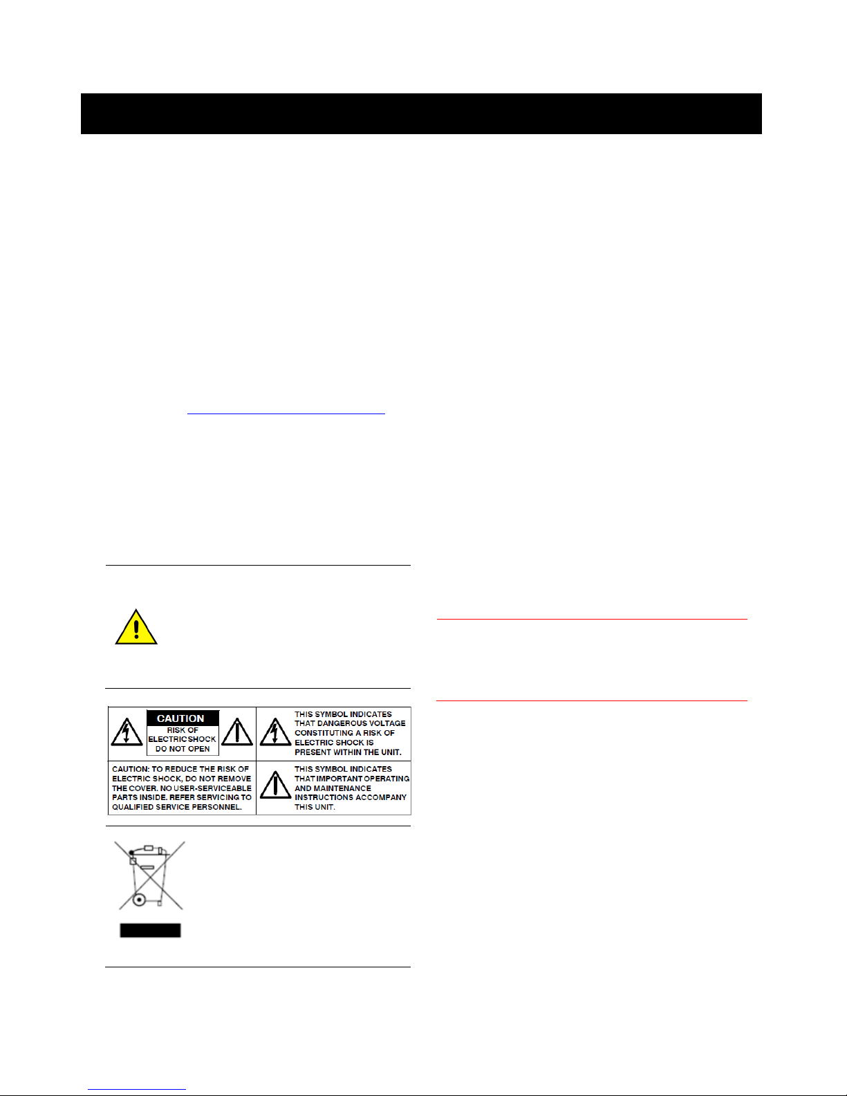
Warnings
Installation and servicing should be performed only by
qualified and experienced technicians to conform to all
local codes and to maintain your warranty.
12V DC/24V AC models require the use of
CSA Certified/UL Listed Class 2 power
adapters to ensure compliance with
electrical safety standards. Power over
Ethernet (PoE) should meet the
IEEE802.3 af PoE standards.
WEEE (Waste Electrical and
Electronic Equipment). Correct
disposal of this product (applicable in
the European Union and other
European countries with separate
collection systems). This product
should be disposed of, at the end of its
useful life, as per applicable local laws,
regulations, and procedures
to
VENTI
D1, 720P Box Camera
FCC Compliance
Information to the user: This equipment has been tested
and found to comply with the limits for a Class B digital
device, Pursuant to Part 15 of the FCC Rules, these limits
are designed to provide reasonable protection against
harmful interference in a residential installation. This
equipment generates, uses, and can radiate radio
frequency energy and, if not installed and used in
accordance with the instruction manual, may cause harmful
interference to radio communications. However, there is no
guarantee that interference will not occur in a particular
installation.
In this equipment does cause harmful interference to radio
or television reception, which can be determined by turning
the equipment off and on, the user is encouraged to try to
correct the interference. For example, try reorienting or
relocating the receiving antenna, increasing the separation
between the equipment and receiver, or connecting the
equipment to an outlet on a different circuit.
Changes or modifications not expressly
Caution
This Class B digital apparatus complies with
Canadian ICES-003.
Europe
The manufacturer declares that the equipment supplied
with this guide is compliant with the essential protection
requirements of EMC directive 2004/108/EC and
General Product Safety Directive GPSD 2001/95/EC,
conforming to requirements of standards EN 55022 for
emissions, EN 50130-4 for immunity.
approved by the party responsible for
compliance could void the user’s authority to
operate the equipment
Series
Quick Guide
1
Page 2

Honeywell
Unpack Everything
One Camera
8-pin terminal block for alarm input/output
One CD containing the software
Prepare for Installation
Select the lens to use with your camera. The VENTI
series Network Camera supports the use of a manual iris
or DC iris lens. When using a DC iris lens, it should be
connected to the camera via the 4-pin square socket
located at the side of the camera.
Mount the Camera
1. Attach the camera to a pending mount.
Insert the screws on the camera stand into either of
the screw holes on the base. Then tighten them up.
2. Mount the camera onto the ceiling/wall and fasten it
securely.
Connect the Wiring
1. CS mount: connect the lens with the camera
2. Screw
3. Back focus Adjustment
4. Base: connect the camera with the tripod
5. SD card slot: insert a SD card into this slot for
recording and storage
6. Video: video output port
7. RJ45 Ethernet Connector/ PoE: insert the RJ45 cable
for network connection. It also supports PoE (Power
over Ethernet).
8. Default: reset all of the camera parameters to factory
default.
9. Reset Button: restart the system.
10. Power Indicator: Red light indicates power connection.
11. I/O Connector: Input/ Output Connector
12. Power Terminal: DC12V/AC24V, red port: power
+/white port: power –/black port: GND. Make sure to
connect the power connector to correct ports (+ and –)
when the power supply is DC12V.
For secure installations, protect surface
mounted cables with plastic or metal
Caution
cable covers.
To avoid damage to the camera, never connect
more than one type of power supply (PoE
IEEE802.3 Ethernet or 12V DC or 24V AC
power plug) at the same time
2
Page 3

Adjust the Field of View
1. Connect an analog monitor to the video output
connection on the back of the camera.
2. Loosen the Zoom and Focus levers on the lens.
Adjust the field of view and focus of the lens to
achieve the desired image on the monitor.
3. Re-tighten the Zoom and Focus levers after the
adjustment is complete.
Network Setup
Setting IP
This is a network-based camera and must be assigned
an IP address first.
1. Enter a default IP address manually. The camera’s
default IP address is 192.168.0.30 and sub mask is
255.255.255.0.
2. Obtain an IP address automatically from the DHCP
server. You don’t need to change the camera’s IP
address if your network uses a DHCP server.
Connecting the Camera to a Personal
Computer
1. Connect the network cable to the camera and then
turn on the camera’s power.
2. Set the personal computer’s IP address. The
camera’s default IP address is 192.168.0.30 and sub
mask is 255.255.255.0.
3. Check that the camera and computer are connected
by Pinging the IP address you have set. To do this,
start a command prompt (Windows: from the Start
Menu, select Program. Then select Accessories and
choose Command Prompt.) Type: Ping 192.168.0.30.
If the message “Reply from…” appears, it means the
connection is done.
4. Start Internet Explorer and enter IP address:
192.168.0.30). A login window will appear. Enter the
default user name: admin and password: 1234 to log
in.
Honeywell
5. Images of the camera can be viewed through Internet
Explorer. Before viewing, follow these steps to enable
the display.
a. Enable Cookies as shown below:
In Internet Explorer, click Internet Options on the
Tools menu.
On the Privacy tab, move the settings slider to Low
or Accept All Cookies.
Click OK.
b. Set Browser setting when proxy server is used
when a proxy server is used.
c. Change Security in Internet options as shown
below:
On tool menu, click Internet Option.
Press the Security tab.
If the camera operates inside the Intranet, click the
Intranet icon. If the camera operates on the Internet,
click the Internet icon.
Click Custom Level. This will open the Security
Settings – Internet Zone screen.
Scroll down to the ActiveX controls and plug-ins
radio buttons and enable all of them as shown in the
illustrations:
Press OK to save the settings. Close all Internet
Explorer Windows and start a new window. This will
allow the new settings to take effect.
6. Type your setting IP address into the browser.
7. Then you should be able to see the camera image
screen.
3
Page 4

Honeywell
Using “IP Finder” to Search
Camera’s IP Address
The IP Finder is a tool which helps users to find network
cameras which you currently monitor from your own
computer. Please note that IP Finder is only compatible
with Windows 7, windows Vista and Windows XP.
1. Insert the CD in the CD-ROM drive.
2. Double click Honeywell_VENTI_IP_Camera(vx).exe
to run the program. Follow the instructions to install.
3. After successfully installing IP Finder, double click the
IP Finder icon which is displayed in your desktop. An
IP Finder window will pop out. The window will display
a list of IP cameras which you are using currently.
4. Press Search to search cameras.
Honeywell
Honeywell Security Asia Pacific
35F Tower A, City Center, 100 Zun Yi Road,
Shanghai 200051, China
TEL +86 21 22196888
FAX +86 21 62370740
http://www.security.honeywell.com/
© 2011 Honeywell International Inc. All rights reserved.
Document 800-09284 Rev. B
4
 Loading...