

Page 1
VE300
Einbauanleitung • Installation instruction • Asennusohje • Instrukcja montazu • Návod na montáž
Инструкция по монтажу
Anleitung zum späteren Gebrauch aufbewahren!
Keep instructions for later use!
Säilytä ohje vastaisen varalle!
Zachowa instrukcj do pózniejszego wykorzystania!
Návod uschovejte pro pozdější použití!
Сохранить инструкцию для последующего
пользования!
EB-VE300 Rev. A
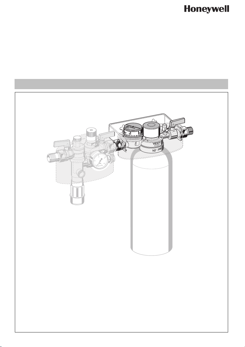
Enthärtungseinheit
Softening unit
Vedenpehmennysyksikköön
Urzdzenie zmikczajce wod
Zmkovací jednotka vody
Установка для снижения
жесткости воды
Page 2

MU1H-1547GE23 R0609 2 Honeywell GmbH
Page 3
D
1. Sicherheitshinweise
1. Beachten Sie die Einbauanleitung.
2. Benutzen Sie das Gerät
• bestimmungsgemäß
• in einwandfreiem Zustand
• sicherheits- und gefahrenbewusst.
3. Beachten Sie, dass das Gerät ausschließlich für
den in dieser Einbauanleitung genannten Verwendungsbereich bestimmt ist. Eine andere oder
darüber hinausgehende Benutzung gilt als nicht
bestimmungsgemäß.
4. Beachten Sie, dass alle Montage-, Inbetriebnahme,
Wartungs- und Justagearbeiten nur durch autorisierte Fachkräfte ausgeführt werden dürfen.
5. Lassen Sie Störungen, welche die Sicherheit beeinträchtigen können, sofort beseitigen.
2. Funktionsbeschreibung
Die unmittelbar nach der Nachfüllkombination installierte Enthärtungseinheit arbeitet nach dem Ionentauscherprinzip und ersetzt die im Wasser befindlichen
Erdalkalien wie Calcium und Magnesium durch Natriumionen.
Abhängig von der regionalen Wasserhärte wird über
die Einstellung der Enthärtungseinheit das Wasser
wahlweise teilenthärtet (<8°dH) oder vollenthärtet
(<0,11°dH).
3. Verwendung
Medium Wasser
Vordruck max. 6,0 bar
Geeignet für Heizungsanlagen mit folgenden
Werkstoffen: Stahl, Kupfer, Kupferlegierungen
und Kunststoffe.
Aufbereitetes Wasser hat veränderte korrosionschemische Parameter. Eine Konditionierung
mittels Inhibitoren ist separat vorzusehen.
4. Technische Daten
Einbaulage waagrecht
Betriebstemperatur max. 30 °C
-Wert 0,45 m3/h
k
vs
1
Anschlussgröße
/2" Außengewinde
5. Lieferumfang
Die Enthärtungseinheit besteht aus:
• Verschneideeinrichtung, bestehend aus Wasserzähler, ausgangsseitiger Absperrmöglichkeit und
Entnahmeventil
• Edelstahl-Haltebügel mit Befestigungsset
• Verschraubungen mit Aussengewinde
• Gesamthärtemessbesteck zur Bestimmung der
Wasserhärte
6. Varianten
VE300-1/2A = Standardausführung mit Gewindean-
schluss R
1
/2"
7. Montage
Beim Einbau sind die Einbauanleitung, geltende
Vorschriften sowie die allgemeinen Richtlinien zu
beachten.
7.1 Einbauhinweise
• Installation im Zulauf der Heizungsanlage, Enthärtungseinheit an der Wand befestigen
• Einbau in waagrechte Rohrleitung
• Der Einbau darf nicht in Räumen oder Schächten
erfolgen, in denen giftige Gase oder Dämpfe
auftreten und die überflutet werden können (Hochwasser)
• Der Einbauort muss frostsicher und gut belüftet sein
• Der Einbauort muss gut zugänglich sein
o Vereinfacht Wartung und Reinigung
• Gemäß DIN EN 1717 in Durchflussrichtung
zunächst Nachfüllkombination, dann unmittelbar
danach Enthärtungseinheit installieren
• Bei der Montage sind die nationalen Installationsvorschriften zu beachten.
• Bei einer Installation ohne Nachfüllkombination vor
der Enthärtungseinheit eine Absperreinrichtung
vorsehen
7.2 Einbau
Bei der Montage gelten die nationalen Installationsvorschriften.
Absperrvorrichtung vorsehen um Patronentausch
sicher zu stellen.
1. Rohrleitung gut durchspülen
2. Enthärtungseinheit einbauen und mittels der Wandhalterung befestigen
• Einbau in waagrechte Rohrleitung
o Durchflussrichtung beachten (Pfeilrichtung)
o spannungs- und biegemomentfrei einbauen
3. Einbauhöhe min. 55cm vom Boden aus vorsehen,
um Patronentausch sicher zu gewährleisten
4. Patrone (siehe Zubehör) in Enthärtungseinheit
schrauben und handfest anziehen
MU1H-1547GE23 R0609 3 Honeywell GmbH
Page 4
D
8. Inbetriebnahme
8.1 Enthärtung einstellen
1. Messung der Wasserhärte
Mit Hilfe des mitgelieferten Gesamthärtemessbestecks sollte vor der Installation die Wasserhärte
gemessen werden.
Beachten Sie die Hinweise in der Anleitung des
Gesamthärtemessbestecks
2. Enthärtungseinheit mit blauem Verstellgriff
einstellen
o Die geeignete Verschneideeinstellung (Markie-
rung 0-3 auf Gehäuse der Enthärtungseinheit, ggf.
Dämmschale entfernen ) ist abhängig von der
regionalen Wasserhärte und der gewünschten
Resthärte. Der Wert kann der auf der Patrone
angebrachten Tabelle entnommen werden.
8.2 Anlage füllen
1. Absperrkugelhähne ein- und ausgangsseitig an der
Enthärtungseinheit langsam öffnen
2. Nach Befüllen der Anlage Absperrkugelhähne
schließen
3. Notieren Sie die auf dem Aufkleber der Patrone
erforderlichen Parameter
9. Instandhaltung
Wartungs-, Instandhaltungs- und Reparaturarbeiten dürfen nur von autorisiertem Fachkräfte
durchgeführt werden.
9.1 Wartung
Wir empfehlen einen Wartungsvertrag mit einem
Installationsunternehmen abzuschließen
Entsprechend DIN EN 1717 muss eine regelmäßige
Wartung durchgeführt werden.
Intervall: 1-3 Jahre (abhängig von den örtlichen
Bedingungen)
Durchführung durch ein Installationsunternehmen.
9.2 Austausch Patrone
Wenn das Füllvolumen der Heizungsanlage die
angegebene Kapazität übersteigt, muss ein
Patronenwechsel vorgenommen werden.
Die maximale Kapazität wird anhand der Gesamt-
wasserhärte und der Verschneideeinstellung
ermittelt. (siehe Tabellen in Kapitel 14)
Die Kapazität wird auf der mitgelieferten Tabelle
notiert, ebenso wie die jeweils nachgefüllten
Wassermengen. Wenn das Füllvolumen den
notierten Wasserzählerendstand übersteigt,
muss ein Patronenwechsel vorgenommen
werden.
Ein Wechsel der Enthärterpatrone wird aus
Gründen der technischen Sicherheit spätestens
12 Monaten nach der ersten Verwendung
empfohlen.
1. Absperrkugelhähne ein- und ausgangsseitig an der
Enthärtungseinheit schließen
2. Ausgangsseite durch Öffnen des Probenahmeven-
tils (Entlüftungsventil an Enthärtungseinheit) druckentlasten
3. Patrone aus Enthärtungseinheit herausdrehen
4. Neue Patrone handfest eindrehen
5. Absperrkugelhähne ein- und ausgangsseitig öffnen
10. Entsorgung
• Gehäuse aus entzinkungsbeständigem Messing
• Mechanische Komponenten der Enthärtungseinheit
aus hochwertigem Kunststoff
• Dichtungen aus EPDM
11. Störungen / Fehlersuche
Störung Ursache Behebung
Kein oder zu wenig Durchfluss Absperrkugelhähne vor oder nach
Absperrkugelhähne ganz öffnen
Nachfüllkombination nicht ganz geöffnet
Honeywell GmbH 4 MU1H-1547GE23 R0609
Page 5
D
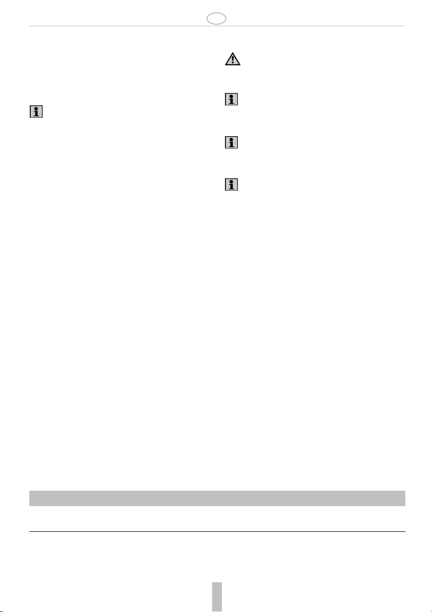
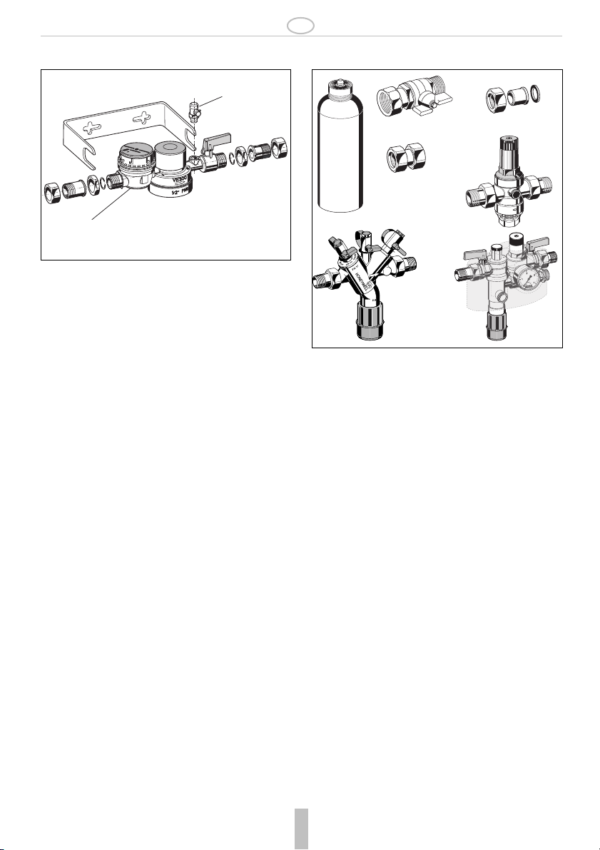
12. Ersatzteile 13. Zubehör
2
1
Nr. Bezeichnung Artikel-Nummer
1 Wasserzähler WZ300
2 Entlüftungsventil 2421100
2192900
AD300
P300-S/L
D
V
G
N
T
BA295
2192900 Absperrkugelhahn
Anschlussgröße
1
/2"
VST06-BAnschluss-Set
Mit Löttülle
P300-S Patrone
0,75l Patrone mit Ionentauscher-Harz
P300-L Patrone
3,5l Patrone mit Ionentauscher-Harz
AD300 Adapter
Zum Anschluss der Enthärtungseinheit an
3/4" Aussengewinde
D06F Druckminderer
Schallschutz-Druckminderer mit Einstellskala
Vordruck max. 16 bar mit Klarsichtsiebtasse,
25 bar mit Messingsiebtasse, Hinterdruck
1,5 - 6 bar
A = Klarsichtsiebtasse bis 40°C / 16 bar
B = Messingsiebtasse bis 70°C / 25 bar
BA295 Systemtrenner
Zur Absicherung von Trinkwasseranlagen
gegen Rückdrücken, Rückfließen und Rücksaugen. Abgesichert werden Flüssigkeiten
bis einschließlich Flüssigkeitskategorie 4
nach DIN EN 1717.
NK300 Nachfüllkombination
Flüssigkeitskategorie 4, mit Manometer,
Absperrkugelhahn und Isolierschale
VST06-B
D06F
NK300
Honeywell GmbH 5 MU1H-1547GE23 R0609
Page 6

D
14. Ermittlung der maximalen Kapazität der Enthärterpatrone
Die Ermittlung der maximalen Kapazität der Enthärterpatrone (Tabellen A und B) erfolgt nach VDI in Bezug
zur Gesamtheizleistung.
14.1 DEUTSCHLAND: Anforderungen lt. VDI 2035 Blatt 1
Gesamtheizleistung spezifisches Anlagenvolumen (Anlagenvolumen/kleinste Einzel-Heizleistung)
0 bis kleiner 20 Liter/kW 20 bis kleiner 50 Liter/kW ab 50 und größer Liter/kW
0 bis 50 kW Richtwert:
Enthärtung auf kleiner 16,8°*
Empfehlung:
Enthärtung auf kleiner 8,4°
⇒ siehe Tabelle A
Mindestanforderung:
Enthärtung auf kleiner 11,2°
Mindestanforderung:
Enthärtung auf kleiner 11,2°
Empfehlung:
Enthärtung auf kleiner 8,4°
⇒ siehe Tabelle A
Mindestanforderung:
Enthärtung auf kleiner 8,4°
Mindestanforderung:
Enthärtung auf kleiner 0,11°
⇒ siehe Tabelle B
Mindestanforderung:
Enthärtung auf kleiner 0,11°
Empfehlung:
Enthärtung auf kleiner 8,4°
50 bis 200 kW
200 bis 600 kW
größer 600 kW
⇒ siehe Tabelle A
Mindestanforderung:
Enthärtung auf kleiner 8,4°
⇒ siehe Tabelle A
Mindestanforderung:
Enthärtung auf kleiner 0,11°
⇒ siehe Tabelle B
⇒ siehe Tabelle A
Mindestanforderung:
Enthärtung auf kleiner 0,11°
⇒ siehe Tabelle B
Mindestanforderung:
Enthärtung auf kleiner 0,11°
⇒ siehe Tabelle B
⇒ siehe Tabelle B
Mindestanforderung:
Enthärtung auf kleiner 0,11°
⇒ siehe Tabelle B
Mindestanforderung:
Enthärtung auf kleiner 0,11°
⇒ siehe Tabelle B
*Bei Anlagen mit Umlaufwasserheizern und für Systeme mit elektrischen Heizelementen beträgt der Richtwert für
die Summe Erdalkalien ≥ 3,0mol/m
³
, entsprechend 16,8 °dH.
14.2 ÖSTERREICH: Anforderungen lt. ÖNORM H 5195-1
Die Ermittlung der maximalen Kapazität der Enthärterpatrone (Tabellen C und D) erfolgt nach Önorm in
Bezug zum Gesamtwasserinhalt der Gesamt-Heizanlage.
Gesamtwasserinhalt der Gesamt-Heizanlage
0 bis 1000 Liter 1000 bis 5000 Liter über 5000 Liter
Mindestanforderung:
Enthärtung auf kleiner 17°
Mindestanforderung:
Enthärtung auf kleiner 6°
Mindestanforderung:
Enthärtung auf kleiner 0,5°
Empfehlung:
Enthärtung auf kleiner 6°
⇒ siehe Tabelle C
Honeywell GmbH 6 MU1H-1547GE23 R0609
⇒ siehe Tabelle C
⇒ siehe Tabelle D
Page 7

D
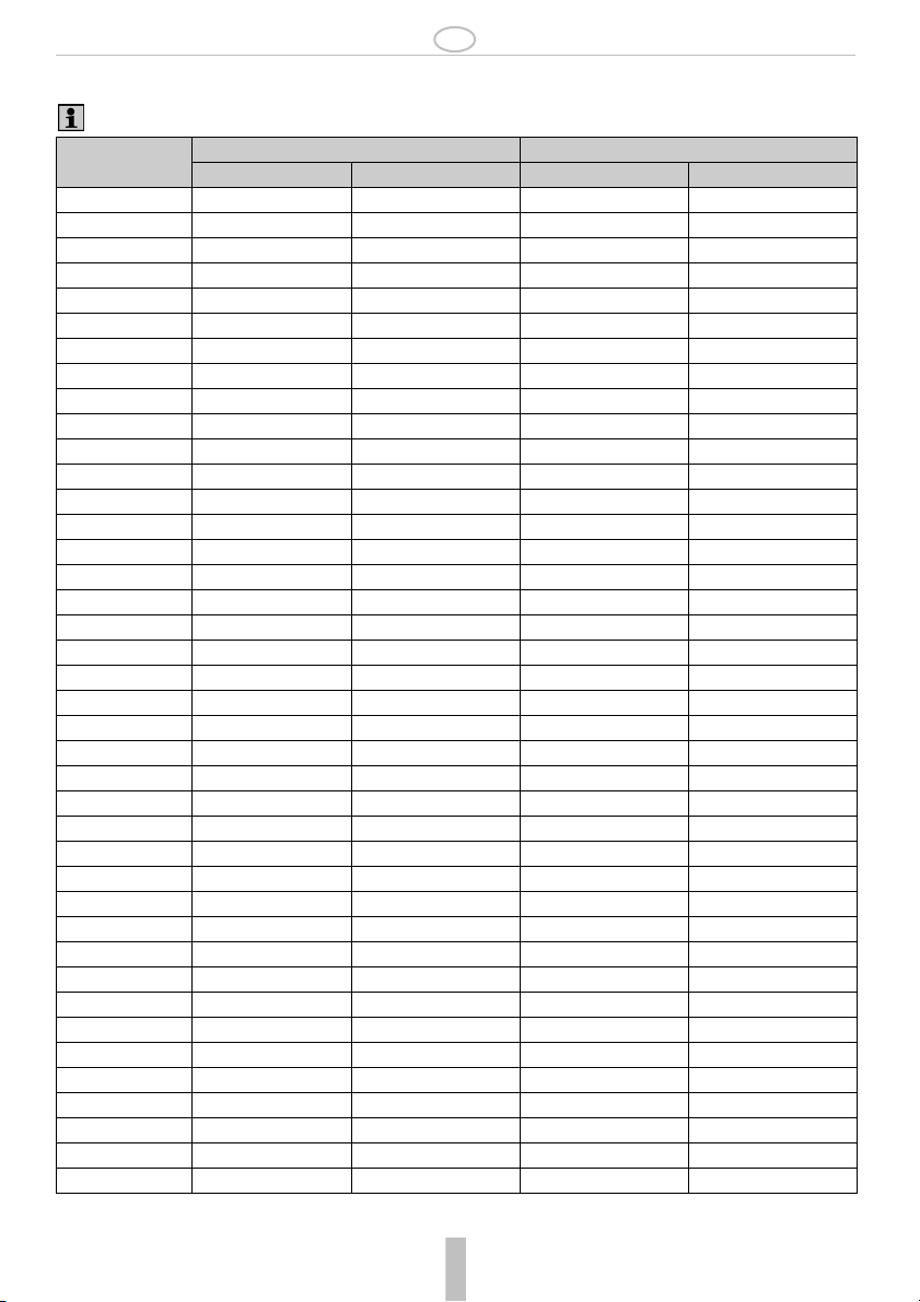
14.3 Tabelle A
Gültig für eine Enthärtung auf eine Resthärte kleiner 8,4°dH (lt. VDI 2035 Blatt 1)
Gesamtwasser-
härte in °dH
Enthärterpatrone Größe S Enthärterpatrone Größe L
Einstellung
Verschneidung
Kapazität in Liter Einstellung
Verschneidung
Kapazität in Liter
1-- -- -- -2-- -- -- -3-- -- -- -4-- -- -- -5-- -- -- -6-- -- -- -7-- -- -- -8-- -- -- --
9 3 650 3 3981
10 3 584 3 3192
11 3 457 3 2131
12 3 351 3 1639
13 3 289 3 1349
14 3 248 3 1155
15 3 217 3 1014
16 2 186 2 868
17 2 168 2 785
18 2 154 2 718
19 2 142 2 661
20 2 132 2 614
21 2 123 2 573
22 2 115 2 538
23 2 109 2 507
24 2 103 2 479
25 2 97 2 455
26 1 88 1 411
27 1 84 1 392
28 1 80 1 375
29 1 77 1 359
30 1 74 1 344
31 1 71 1 331
32 1 68 1 318
33 1 66 1 307
34 1 63 1 296
35 1 61 1 286
36 1 59 1 277
37 1 57 1 268
38 1 56 1 260
39 1 54 1 252
40 1 53 1 245
Honeywell GmbH 7 MU1H-1547GE23 R0609
Page 8

D
14.4 Tabelle B
Gültig für eine Enthärtung auf eine Resthärte kleiner 0,11°dH (lt. VDI 2035 Blatt 1)
Gesamtwasser-
härte in °dH
Enthärterpatrone Größe S Enthärterpatrone Größe L
Einstellung
Verschneidung
Kapazität in Liter Einstellung
Verschneidung
Kapazität in Liter
1-------2 0 900 0 4200
3 0 600 0 2800
4 0 450 0 2100
5 0 360 0 1680
6 0 300 0 1400
7 0 257 0 1200
8 0 225 0 1050
9 0 200 0 933
10 0 180 0 840
11 0 164 0 764
12 0 150 0 700
13 0 138 0 646
14 0 129 0 600
15 0 120 0 560
16 0 113 0 525
17 0 106 0 494
18 0 100 0 467
19 0 95 0 442
20 0 90 0 420
21 0 86 0 400
22 0 82 0 382
23 0 78 0 365
24 0 75 0 350
25 0 72 0 336
26 0 69 0 323
27 0 67 0 311
28 0 64 0 300
29 0 62 0 290
30 0 60 0 280
31 0 58 0 271
32 0 56 0 263
33 0 55 0 255
34 0 53 0 247
35 0 51 0 240
36 0 50 0 233
37 0 49 0 227
38 0 47 0 221
39 0 46 0 215
40 0 45 0 210
MU1H-1547GE23 R0609 8 Honeywell GmbH
Page 9

D
14.5 Tabelle C
Gültig für eine Enthärtung auf eine Resthärte kleiner 6°dH (lt. ÖNORM H 5195-1)
Gesamtwasser-
härte in °dH
Enthärterpatrone Größe S Enthärterpatrone Größe L
Einstellung
Verschneidung
Kapazität in Liter Einstellung
Verschneidung
Kapazität in Liter
1-- -- -- -2-- -- -- -3-- -- -- -4-- -- -- -5-- -- -- -6-- -- -- -7 3 602 3 3110
8 3 550 3 2809
9 3 435 3 2030
10 3 347 3 1617
11 3 278 3 1298
12 2 240 2 1120
13 2 212 2 988
14 2 190 2 885
15 2 172 2 803
16 1 150 1 701
17 1 138 1 646
18 1 129 1 600
19 1 120 1 560
20 1 112 1 525
21 1 106 1 494
22 1 100 1 467
23 1 95 1 442
24 1 90 1 421
25 1 86 1 401
26 1 82 1 383
27 1 79 1 366
28 1 75 1 351
29 1 72 1 338
30 1 70 1 325
31 1 67 1 313
32 1 65 1 302
33 1 63 1 292
34 1 60 1 282
35 1 59 1 273
36 1 57 1 265
37 1 55 1 257
38 1 53 1 250
39 1 52 1 243
40 1 51 1 236
Honeywell GmbH 9 MU1H-1547GE23 R0609
Page 10

D
14.6 Tabelle D
Gültig für eine Enthärtung auf eine Resthärte kleiner 0,5°dH (lt. ÖNORM H 5195-1)
Gesamtwasser-
härte in °dH
Enthärterpatrone Größe S Enthärterpatrone Größe L
Einstellung
Verschneidung
Kapazität in Liter Einstellung
Verschneidung
Kapazität in Liter
1-------2 0 935 0 4362
3 0 623 0 2908
4 0 467 0 2181
5 0 374 0 1745
6 0 312 0 1454
7 0 267 0 1246
8 0 234 0 1091
9 0 208 0 969
10 0 187 0 872
11 0 170 0 793
12 0 156 0 727
13 0 144 0 671
14 0 134 0 623
15 0 125 0 582
16 0 117 0 545
17 0 110 0 513
18 0 104 0 485
19 0 98 0 459
20 0 93 0 436
21 0 89 0 415
22 0 85 0 397
23 0 81 0 379
24 0 78 0 364
25 0 75 0 349
26 0 72 0 336
27 0 69 0 323
28 0 67 0 312
29 0 64 0 301
30 0 62 0 291
31 0 60 0 281
32 0 58 0 273
33 0 57 0 264
34 0 55 0 257
35 0 53 0 249
36 0 52 0 242
37 0 51 0 236
38 0 49 0 230
39 0 48 0 224
40 0 47 0 218
MU1H-1547GE23 R0609 10 Honeywell GmbH
Page 11
GB
1. Safety Guidelines
1. Follow the installation instructions.
2. Use the appliance
• according to its intended use
• in good condition
• with due regard to safety and risk of danger.
3. Note that the appliance is exclusively for use in the
applications detailed in these installation instructions. Any other use will not be considered to comply
with requirements and would invalidate the
warranty.
4. Please take note that any assembly, commissioning, servicing and adjustment work may only be
carried out by authorized persons.
5. Immediately rectify any malfunctions which may
influence safety.
2. Functional description
The softening unit, installed directly after the refilling
combination, works according to the ionic exchange
principle and replaces the alkaloids of soil such as
calcium and magnesium with sodium ions.
Dependant on the regional water hardness, the water
is either partially softened (<8°dH) or completely
softened (<0,11°dH) by adjusting the blending unit.
3. Application
Medium Water
Inlet pressure max. 6.0 bar
Suitable for heating systems with the following materials: steel, copper, copper alloys and plastics.
Treated water has modified corrosive chemical parameters. Conditioning by means of inhibitors is to be
provided for separately.
4. Technical data
Installation position horizontal
Operating temperaturemax. 30 °C
-value 0.45 m3/h
k
vs
1
Connection size
/2" External thread
5. Scope of delivery
The softening unit consists of:
• Blending unit, consisting of water flow meter, outletsided blocking capability and bleeder valve
• Stainless steel mounting bracket with connection
set
• Threaded male connections
• Total hardness test-kit to determine water hardness
6. Options
VE300-1/2A = Standard version with threaded
connection R
1
/2"
7. Assembly
It is necessary during installation to follow the installation instructions, to comply with local requirements and
to follow the codes of good practice.
7.1 Installations Guidelines
• Installation in inlet of the heating system, fasten
softening unit on the wall
o Installation into horizontal pipework
• The installation may not take place in areas or ducts
where poisonous gases or vapours may be present
or where flooding can occur
• The installation environment should be protected
against frost and ventilated well
• The installation location has to be easily accessible
o Simplified maintenance and cleaning
• According to DIN EN 1717 first install the refilling
combination in the flow direction, then immediately
thereafter install the softening unit
• The national installation regulations must be
observed during the assembly.
• Install a shutoff facility before the softening unit in
case of installation without refillig combination
7.2 Installation
The national installation regulations apply during
the assembly.
Provide shut-off device to safeguard cartridge
exchange
1. Thoroughly flush pipework
2. Install the blending unit and fasten with the wall
holder
o Installation into horizontal pipework
• Note flow direction (indicated by arrow)
o Install without tension or bending stresses
3. Set installation height min. 55cm from the ground to
ensure reliable cartridge exchange.
4. Screw cartridge (see accessories) into blending unit
and tighten manually
MU1H-1547GE23 R0609 11 Honeywell GmbH
Page 12
GB
8. Commissioning
8.1 Adjust softening
1. Measuring the water hardness with support from the
total hardness test-kit, included in the scope of delivery, the water hardness should be measured
before the installation.
Observe the information in the instruction manual
of the total hardness test-kit
2. Set the dilution unit with the blue adjustment handle
o The suitable dilution setting (marker 0-3 on the
casing of the dilution unit, remove insulation lining
if necessary) is dependant on the regional water
hardness and the desired residual hardness. The
value can be extracted from the table attached to
the cartridge.
8.2 Filling up the system
1. Slowly open the ball valve on the inlet and outlet
side of the blending unit
2. After filling up the system, close the ball valves
3. Note the required parameters listed on the label on
the cartridge
9. Maintenance
Maintenance, service and repair work may be
carried out only by authorised technicians.
9.1 Maintenance
We recommend a planned maintenance contract
with an installation company
In accordance with DIN EN 1717 a regular maintenance must be taken.
Frequency: every 1-3 years (depending on local
operating conditions)
To be carried out by an installation company
9.2 Replacing cartridge
When the filling level of the heating system
exceeds the specified capacity, a cartridge
exchange has to be performed.
The maximum capacity is determined according
to the total water hardness and the dilution
setting. (see table in chapter 14)
The capacity is noted on a table included in the
scope of delivery, as well as the respectively
added amounts of water. If the filling level
exceeds the noted water flow meter end value, a
cartridge exchange has to be performed.
An exchange of the softening cartridge is recommended at least 12 months after its first usage
due to technical safety purposes.
1. Close the ball valve on the inlet and outlet side of the
blending unit
2. Decompress the outlet side by opening the
sampling valve (air bleed valve of the blending unit)
3. Unscrew the cartridge from the blending unit
4. Screw the new cartridge in manually
5. Open ball valves on the inlet and outlet side
10. Disposal
• Dezincification-resistant brass housing
• Mechanical components of the blending unit made
of high-quality synthetic material
• EPDM sealing washers
11. Troubleshooting
Problem Cause Remedy
No or too small water flow rate Ball valves up- or downstream of refilling
Open ball valves entirely
combination are not fully open
Honeywell GmbH 12 MU1H-1547GE23 R0609
Page 13

GB
12. Spare Parts 13. Accessories
2
1
No.Description Part No.
1 Water flow meter WZ300
2 Air bleed valve 2421100
2192900
AD300
P300-S/L
D
V
G
N
T
BA295
2192900 Shutoff valve
Connection size
1
/2"
VST06-B Connection set
Solder connections
P300-S Cartridge
0,75l cartridge with ionic exchange resin
P300-L Cartridge
3.5l cartridge with ionic exchange resin
AD300 Adapter
To fit the softening unit to a 3/4“ male
connection.
D06F Pressure reducing valve
Noise protected pressure reducing valve
with setting scale. Maximum inlet pressure
16 bar, with brass filter bowl 25 bar, outlet
pressure range 1.5 - 6.0 bar
A = With clear filter bowl up to 40 °C / 16 bar
B = With brass filter bowl up to 70 °C / 25 bar
BA295 Backflow Preventer
To protect drinking water systems against
back pressure, backflow and withdrawal.
Protection against fluids up to and including
fluid category 4 acc. to DIN EN 1717.
NK300 Refilling combination
Liquid catagory 4, with pressure gauge,
shutoff valve and isolating shell
VST06-B
D06F
NK300
Honeywell GmbH 13 MU1H-1547GE23 R0609
Page 14
GB
14. Determination of the maximum capacity of the softening cartridge
The determination of the maximum capacity of the softening cartridge (tables A and B) is carried out in accordance with VDI (Verein Deutscher Ingenieure - Society of German Engineers) in relation to the overall
heating power.
14.1 GERMANY: Requirements according to VDI 2035 page 1
Overall heating
power
0 to 50 kW Reference value:
50 to 200 kW Minimum requirement:
Specific system volume (system volume/smallest individual heating power)
0 to less than 20 litres/kW 20 to less than 50 litres/kW as of 50 and more litres/kW
Softening to less than 16,8°*
Recommendation:
Softening to less than 8.4°
⇒ See table A
Softening to less than 11.2°
Minimum requirement:
Softening to less than 11.2°
Recommendation:
Softening to less than 8.4°
⇒ See table A
Minimum requirement:
Softening to less than 8.4°
Minimum requirement:
Softening to less than 0.11°
⇒ See table B
Minimum requirement:
Softening to less than 0.11°
Recommendation:
Softening to less than 8.4°
⇒ See table A
200 to 600 kW Minimum requirement:
Softening to less than 8.4°
⇒ See table A
more than 600 kW Minimum requirement:
Softening to less than 0.11°
⇒ See table B
⇒ See table A
Minimum requirement:
Softening to less than 0.11°
⇒ See table B
Minimum requirement:
Softening to less than 0.11°
⇒ See table B
⇒ See table B
Minimum requirement:
Softening to less than 0.11°
⇒ See table B
Minimum requirement:
Softening to less than 0.11°
⇒ See table B
*For equipment with circulating water heaters and for systems with electrical heating elements, the equated refe-
³
rence value for the sum of alkaline earth metals ≥ 3.0mol/m
, equivelent to 16.8 °dH.
14.2 AUSTRIA: Requirements according to ÖNORM H 5195-1
The determination of the maximum capacity of the softening cartridge (tables C and D) is carried out in accordance with the Önorm (Österreichisches Normungsinstitut - Austrian standardisation institute) in relation to
the overall water content of the entire heating system.
Overall water content of the entire heating system
0 to 1000 litres 1000 to 5000 litres Over 5000 litres
Minimum requirement:
Softening to less than 17°
Minimum requirement:
Softening to less than 6°
Minimum requirement:
Softening to less than 0.5°
Recommendation:
Softening to less than 6°
⇒ See table C
Honeywell GmbH 14 MU1H-1547GE23 R0609
⇒ See table C
⇒ See table D
Page 15

GB
14.3 Table A
Valid for a softening to a residual hardness less than 8.4°dH (according to VDI 2035 page 1)
Total water hard-
ness in °dH
Softening cartridge Size S Softening cartridge Size L
Dilution adjustment Capacity in litres Dilution adjustment Capacity in litres
1-- -- -- -2-- -- -- -3-- -- -- -4-- -- -- -5-- -- -- -6-- -- -- -7-- -- -- -8-- -- -- --
9 3 650 3 3981
10 3 584 3 3192
11 3 457 3 2131
12 3 351 3 1639
13 3 289 3 1349
14 3 248 3 1155
15 3 217 3 1014
16 2 186 2 868
17 2 168 2 785
18 2 154 2 718
19 2 142 2 661
20 2 132 2 614
21 2 123 2 573
22 2 115 2 538
23 2 109 2 507
24 2 103 2 479
25 2 97 2 455
26 1 88 1 411
27 1 84 1 392
28 1 80 1 375
29 1 77 1 359
30 1 74 1 344
31 1 71 1 331
32 1 68 1 318
33 1 66 1 307
34 1 63 1 296
35 1 61 1 286
36 1 59 1 277
37 1 57 1 268
38 1 56 1 260
39 1 54 1 252
40 1 53 1 245
Honeywell GmbH 15 MU1H-1547GE23 R0609
Page 16
GB
14.4 Table B
Valid for a softening to a residual hardness less than 0.11°dH (according to VDI 2035 page 1)
Total water hard-
ness in °dH
Softening cartridge Size S Softening cartridge Size L
Dilution adjustment Capacity in litres Dilution adjustment Capacity in litres
1-------2 0 900 0 4200
3 0 600 0 2800
4 0 450 0 2100
5 0 360 0 1680
6 0 300 0 1400
7 0 257 0 1200
8 0 225 0 1050
9 0 200 0 933
10 0 180 0 840
11 0 164 0 764
12 0 150 0 700
13 0 138 0 646
14 0 129 0 600
15 0 120 0 560
16 0 113 0 525
17 0 106 0 494
18 0 100 0 467
19 0 95 0 442
20 0 90 0 420
21 0 86 0 400
22 0 82 0 382
23 0 78 0 365
24 0 75 0 350
25 0 72 0 336
26 0 69 0 323
27 0 67 0 311
28 0 64 0 300
29 0 62 0 290
30 0 60 0 280
31 0 58 0 271
32 0 56 0 263
33 0 55 0 255
34 0 53 0 247
35 0 51 0 240
36 0 50 0 233
37 0 49 0 227
38 0 47 0 221
39 0 46 0 215
40 0 45 0 210
MU1H-1547GE23 R0609 16 Honeywell GmbH
Page 17

GB
14.5 Table C
Valid for a softening to a residual hardness less than 6°dH (according to ÖNORM H 5195-1)
Total water hard-
ness in °dH
Softening cartridge Size S Softening cartridge Size L
Dilution adjustment Capacity in litres Dilution adjustment Capacity in litres
1-------2-------3-------4-------5-------6-------7 3 602 3 3110
8 3 550 3 2809
9 3 435 3 2030
10 3 347 3 1617
11 3 278 3 1298
12 2 240 2 1120
13 2 212 2 988
14 2 190 2 885
15 2 172 2 803
16 1 150 1 701
17 1 138 1 646
18 1 129 1 600
19 1 120 1 560
20 1 112 1 525
21 1 106 1 494
22 1 100 1 467
23 1 95 1 442
24 1 90 1 421
25 1 86 1 401
26 1 82 1 383
27 1 79 1 366
28 1 75 1 351
29 1 72 1 338
30 1 70 1 325
31 1 67 1 313
32 1 65 1 302
33 1 63 1 292
34 1 60 1 282
35 1 59 1 273
36 1 57 1 265
37 1 55 1 257
38 1 53 1 250
39 1 52 1 243
40 1 51 1 236
Honeywell GmbH 17 MU1H-1547GE23 R0609
Page 18

GB
14.6 Table D
Valid for a softening to a residual hardness less than 0.5°dH (according to ÖNORM H 5195-1)
Total water hard-
ness in °dH
Softening cartridge Size S Softening cartridge Size L
Dilution adjustment Capacity in litres Dilution adjustment Capacity in litres
1-------2 0 935 0 4362
3 0 623 0 2908
4 0 467 0 2181
5 0 374 0 1745
6 0 312 0 1454
7 0 267 0 1246
8 0 234 0 1091
9 0 208 0 969
10 0 187 0 872
11 0 170 0 793
12 0 156 0 727
13 0 144 0 671
14 0 134 0 623
15 0 125 0 582
16 0 117 0 545
17 0 110 0 513
18 0 104 0 485
19 0 98 0 459
20 0 93 0 436
21 0 89 0 415
22 0 85 0 397
23 0 81 0 379
24 0 78 0 364
25 0 75 0 349
26 0 72 0 336
27 0 69 0 323
28 0 67 0 312
29 0 64 0 301
30 0 62 0 291
31 0 60 0 281
32 0 58 0 273
33 0 57 0 264
34 0 55 0 257
35 0 53 0 249
36 0 52 0 242
37 0 51 0 236
38 0 49 0 230
39 0 48 0 224
40 0 47 0 218
MU1H-1547GE23 R0609 18 Honeywell GmbH
Page 19

FIN
1. Turvallisuusohjeita
1. Noudata asennusohjetta.
2. Käytä laitetta
• tarkoituksenmukaisesti
• moitteettomassa kunnossa
• turvallisuus- ja vaaratekijät huomioiden
3. Huomaa, että laite on tarkoitettu käytettäväksi
ainoastaan tässä asennusohjeessa mainittuun käyttötarkoitukseen. Muu tai tämän ylittävä käyttö katsotaan tarkoituksenvastaiseksi.
4. Vain koulutetut asentajat saavat asentaa, ottaa,
käyttöön ja huoltaa laitteita.
5. Korjaa turvallisuuteen mahdollisesti haitallisesti
vaikuttavat toimintahäiriöt välittömästi.
2. Toiminnan kuvaus
Täyttöryhmän jälkeen asennettu vedenpehmennysyksikkö toimii ioninvaihtoperiaatteen mukaan ja korvaa
veden sisältämät maa-alkalit, kuten kalsiumin ja
magnesiumin, natriumioneilla.
Vedenpehmennysyksikkö säädetään veden kovuuden
mukaan niin, että vesi pehmennetään osittain (<8°dH)
tai kokokaan (<0,11°dH).
3. Käyttö
Väliaine vesi
Alkupaine max. 6,0 bar
Soveltuu lämmitysjärjestelmiin, jotka sisältävät
seuraavia materiaaleja:- teräs, kupari, kupariseokset ja muovit.
Puhdistetulla vedellä on muuttuneet korroosiokemialliset parametrit. Inhibiittorikäsittely tarvitaan
erikseen.
4. Tekniset tiedot
Asennusasento vaakasuora
Käyttölämpötila max. 30 °C
-arvo 0,45 m3/h
k
vs
1
Liitännät
/2" ulkokierre
5. Toimituslaajuus
Vedenpehmennysyksikköön kuuluvat:
• Automaattinen sekoitulaite, jossa on vesimittari,
lähtöpuolen sulkumahdollisuus ja ottoventtiili
• Jaloteräksinen sanka kiinnityssarjoineen
• Ulkokierteelliset liittimet
• Veden kovudeen mittausvälineet
6. Toimituslaajuus
1
VE300-1/2A = vakiomalli, kierreliitäntä R
/2"
7. Asennus
Asennettaessa on noudatettava asennusohjeita,
voimassa olevia määräyksiä sekä yleisiä ohjeita.
7.1 Yleistä
• Asennus lämmitysjärjestelmän syöttöön, vedenpehmennysyksikkö kiinnitetään seinälle
• Asennus lämmitysjärjestelmän syöttöön, vedenpehmennysyksikkö kiinnitetään seinälle
• Yksikköä ei saa asentaa tiloihin tai kuiluihin, joissa
on myrkyllisiä kaasuja tai höyryjä ja jotka voivat
täyttyä tulvivalla vedellä.
• Asennuspaikan on oltava jäätymätön ja hyvin tuuletettu
• Asennuspaikan on oltava helppopääsyinen
o Kunnossapidon ja puhdistuksen on oltava helposti
tehtävissä
• Asenna DIN EN 1717 mukaan virtaussuunnassa en
täyttöryhmä ja heti sen jälkeen vedenpehmennysyksikkö
• Kansallisia asennusmääräyksiä on noudatettava.
• Jos täyttöryhmää ei asenneta, vedenpehmennysyksikön eteen on asennettava sulkuventtiili
7.2 Asennus
Asennettaessa on noudatettava kansallisia
määräyksiä.
Asenna sulkuventtiili, jotta patruuna voitaisiin
vaihtaa.
1. Huuhtele putkisto huolellisesti.
2. Asenna vedenpehmennysyksikkö ja kiinnitä seinäpitimellä
• Asennus lämmitysjärjestelmän syöttöön, vedenpehmennysyksikkö kiinnitetään seinälle
o Ota huomioon virtaussuunta (nuolen suunta)
o Asennus vaakaputkistoon suodatinpesä alaspäin
3. Asenna väh. 55 cm korkeudella lattiasta, jotta patruunan saisi vaihdettua helposti
4. Kiinnitä patruuna vedenpehmennysyksikkö ja kiristä
käsivoimin
MU1H-1547GE23 R0609 19 Honeywell GmbH
Page 20

FIN
8. Käyttöönotto
8.1 Vedenpehmennyksen säätäminen
1. Veden kovuuden mittaaminen
Mittaa veden kovuus mukana toimitetuilla mittausvälineillä ennen asennusta.
Noudata mittausvälineiden ohjeita
2. Säädä vedenpehmennyslaite sinisellä kahvalla
o Säädä sopiva sekoitussuhde (pehmennysyksikö
kotelon merkintä 0-3, poista eristyskuori tarvittaessa) riippuu paikallisen veden kovuudesta ja
halutusta loppukovuudesta. Arvon voi katsoa
myös patruunan taulukossa.
8.2 Täytä järjestelmä
1. Avaa vedenpehmennysyksikön tulo- ja lähtöpuolen
sulkuhanat hitaasti
2. Kun järjestelmä on täynnä, sulje sulkuhanat
3. Merkitse vaadittavat parametrit patruunan tarraan
9. Huolto- ja ylläpito
Vain valtuutetut asentajat saavat huoltoaa,
kunnosta ja korjata yksikköä.
9.1 Huolto
Suosittelemme tekemään huoltosopimuksen LVI-
alan liikkeen kanssa
DIN EN 1717:n mukaan laitteisto on huollettava
säännöllisesti.
Huoltoväli: 1-3 vuoden välein (paikallisista
määräyksistä riippuen)
LVI-yrityksen toimesta
9.2 Patruunan vaihtaminen
Jos lämmitysjärjestelmän täyttötilavuus ylittää
ilmoitetun kapasiteetin, patruuna on vaihdettavawerden.
Enimmäiskapasiteetti perustuu veden kokonaiskovuuteen ja sekoitusuhteen säätöön. (Katso
luvun 14 taulukot.)
Kapasiteetti merkitään mukana toimitettuun
taulukkoon, samoin lisätyt vesimäärät. Kun täyttömäärä ylittää muistiin merkityn vesimittarin
lukeman, patruuna on vaihdettava.
Vedenpehmennyspatruunan vaihtoa suositellaan
teknisen turvallisuuden takia viimeistään 12
kuukauden kuluttua enimmäisen käyttökerran
jälkeen.
1. Sulje vedenpehmennysyksikön tulo- ja lähtöpuolen
sulkuhanat
2. Poista lähtöpuolen paine avaamalla näytteenottoventtiili (vedenpehmennysyksikön ilmausventtiili)
3. Irrota patruuna vedenpehmennysyksiköstä
4. Kierrä uusi patruuna kiinni käsivoimin
5. Avaa tulo- ja poistopuolen sulkuhanat
10. Käytöstä poisto
• Pesä sinkkikadon kestävää messinkiä
• Vedenpehmennysyksikön mekaaniset osat laadukasta muovia
• Tiivisteen materiaali EPDM
11. Häiriöt / Virheenetsintä
Häiriö Häiriön syy Korjaustoimenpiteet
Ei virtausta tai liian pieni virtaus Täyttöryhmän sulkuhanoja ei ole avattu
Avaa sulkuhanat kokonaan
kokonaan
Honeywell GmbH 20 MU1H-1547GE23 R0609
Page 21

FIN
12. Varaosat 13. Lisätarvikkeet
2
1
1 Vesimittari WZ300
2 Ilmausventtiili 2421100
2192900
AD300
P300-S/L
D
V
G
N
T
BA295
2192900 Sulkuhana
1
Liitäntä
/2"
VST06-B Liitäntäsarja
Juotosliitäntä
P300-S Patruuna
0,75 l, sisältää ioninvaihtohartsia
P300-L Patruuna
3,5 l, sisältää ioninvaihtohartsia
AD300 Adapteri
Vedenpehmennysyksikön liittämiseksi 3/4"
ulkokierteeseen
D06F Paineenalennusventtiili
Meluton paineenalennusventtiili, säätöasteikko
max. 16 bar (läpinäkyvä suodatinpesä), 25 bar
(messinkisuodatinsuodatin), lähtöpaine 1,56bar
A = läpinäkyvä suodatinpesä 40°C / 16 bar asti
B = messinkisuodatinpesä 70°C / 25 bar asti
BA295 Takaisinvirtauksen estin
Suojaa juomavesijärjestelmiä takaisinvirtaukselta ja -imulta. Suojaa nesteiltä aina nestekategoriaan 4 asti (DIN EN 1717).
NK300 Täyttöryhmä
Nestekategoria 4, painemittari, sulkuhana ja
eristekuori
VST06-B
D06F
NK300
Honeywell GmbH 21 MU1H-1547GE23 R0609
Page 22

FIN
14. Vedenpehmenninpatruuna maksimikapasiteetin määrittäminen
Vedenpehmenninpatruunan maksimaalinen kapasiteetti (taulukot A ja B) määritellään VDI:n mukaan kokonaislämmitysteho perusteella.
14.1 SAKSA: Vaatimukset VDI 2035 Blatt 1 mukaan
Kokonaislämmity-
steho
Järjestelmän ominaisuustilavuus (järjestelmän tilavuus/pienin yksittäinen lämmity-
steho)
0 < 20 litraa/kW 20 < 50 litraa/kW 50 ja suurempi litraa /kW
0 - 50 kW Ohjearvo:
Kovuus alle 16,8°*
Suositus:
Kovuus alle 8,4°
⇒ katso taulukko A
50 - 200 kW Vähimmäisvaatimus:
Kovuus alle 11,2°
Vähimmäisvaatimus:
Kovuus alle 11,2°
Suositus:
Kovuus alle 8,4°
⇒ katso taulukko A
Vähimmäisvaatimus:
Kovuus alle 8,4°°
Vähimmäisvaatimus:
Kovuus alle 0,11°
⇒ katso taulukko B
Vähimmäisvaatimus:
Kovuus alle 0,11°
Suositus:
Kovuus alle 8,4°°
⇒ katso taulukko A
200 - 600 kW Vähimmäisvaatimus:
Kovuus alle 8,4°°
⇒ katso taulukko A
yli 600 kW Vähimmäisvaatimus:
Kovuus alle 0,11°
⇒ katso taulukko B
⇒ katso taulukko A
Vähimmäisvaatimus:
Kovuus alle 0,11°
⇒ katso taulukko B
Vähimmäisvaatimus:
Kovuus alle 0,11°
⇒ katso taulukko B
⇒ katso taulukko B
Vähimmäisvaatimus:
Kovuus alle 0,11°
⇒ katso taulukko B
Vähimmäisvaatimus:
Kovuus alle 0,11°
⇒ katso taulukko B
*Vesikiertojärjestelmien ja sähkövastuksilla lämmitettävien järjestelmien maa-alkalien summan ohjearvo ≥ 3,0mol/
m³, mikä vastaa 16,8 °dH.
14.2 ITÄVALTA: Vaatimukset ÖNORM H 5195-1 mukaan
Pehmennyspatruunoiden maksimaalinen kapasiteetti (taulukot C ja D) määritellään Önormin mukaan koko
lämmitysjärjestelmän kokonaisvesimäärän perusteella.
Koko lämmitysjärjestelmän kokonaisvesimäärä
0 - 1000 litraa 1000 - 5000 litraa yli 5000 litraa
Vähimmäisvaatimus:
Kovuus alle 17°
Vähimmäisvaatimus:
Kovuus alle 6°
Vähimmäisvaatimus:
Kovuus alle 0,5°
Suositus:
Kovuus alle 6°
⇒ katso taulukko C
Honeywell GmbH 22 MU1H-1547GE23 R0609
⇒ katso taulukko C
⇒ katso taulukko D
Page 23

14.3 Taulukko A
Koskee jäännöskovuutta alle 8,4°dH (VDI 2035 Blatt 1)
FIN
Veden kokonaisko-
vuus °dH
1-- -- -- -2-- -- -- -3-- -- -- -4-- -- -- -5-- -- -- -6-- -- -- -7-- -- -- -8-- -- -- --
9 3 650 3 3981
10 3 584 3 3192
11 3 457 3 2131
12 3 351 3 1639
13 3 289 3 1349
14 3 248 3 1155
15 3 217 3 1014
16 2 186 2 868
17 2 168 2 785
18 2 154 2 718
19 2 142 2 661
20 2 132 2 614
21 2 123 2 573
22 2 115 2 538
23 2 109 2 507
24 2 103 2 479
25 2 97 2 455
26 1 88 1 411
27 1 84 1 392
28 1 80 1 375
29 1 77 1 359
30 1 74 1 344
31 1 71 1 331
32 1 68 1 318
33 1 66 1 307
34 1 63 1 296
35 1 61 1 286
36 1 59 1 277
37 1 57 1 268
38 1 56 1 260
39 1 54 1 252
40 1 53 1 245
Pehmennyspatruuna koko S Pehmennyspatruuna koko L
Sekoitusventtiilin
säätö
Kapasiteetti litraa Sekoitusventtiilin
säätö
Kapasiteetti litraa
Honeywell GmbH 23 MU1H-1547GE23 R0609
Page 24

14.4 Taulukko B
Koskee jäännöskovuutta alle 0,11 °dH (VDI 2035 Blatt 1)
FIN
Veden kokonaisko-
vuus °dH
1-------2 0 900 0 4200
3 0 600 0 2800
4 0 450 0 2100
5 0 360 0 1680
6 0 300 0 1400
7 0 257 0 1200
8 0 225 0 1050
9 0 200 0 933
10 0 180 0 840
11 0 164 0 764
12 0 150 0 700
13 0 138 0 646
14 0 129 0 600
15 0 120 0 560
16 0 113 0 525
17 0 106 0 494
18 0 100 0 467
19 0 95 0 442
20 0 90 0 420
21 0 86 0 400
22 0 82 0 382
23 0 78 0 365
24 0 75 0 350
25 0 72 0 336
26 0 69 0 323
27 0 67 0 311
28 0 64 0 300
29 0 62 0 290
30 0 60 0 280
31 0 58 0 271
32 0 56 0 263
33 0 55 0 255
34 0 53 0 247
35 0 51 0 240
36 0 50 0 233
37 0 49 0 227
38 0 47 0 221
39 0 46 0 215
40 0 45 0 210
Pehmennyspatruuna koko S Pehmennyspatruuna koko L
Sekoitusventtiilin
säätö
Kapasiteetti litraa Sekoitusventtiilin
säätö
Kapasiteetti litraa
MU1H-1547GE23 R0609 24 Honeywell GmbH
Page 25

14.5 Taulukko C
Koskee jäännöskovuutta alle 6°dH (VDI 5195 Blatt -1)
FIN
Veden kokonaisko-
vuus °dH
1-- -- -- -2-- -- -- -3-- -- -- -4-- -- -- -5-- -- -- -6-- -- -- -7 3 602 3 3110
8 3 550 3 2809
9 3 435 3 2030
10 3 347 3 1617
11 3 278 3 1298
12 2 240 2 1120
13 2 212 2 988
14 2 190 2 885
15 2 172 2 803
16 1 150 1 701
17 1 138 1 646
18 1 129 1 600
19 1 120 1 560
20 1 112 1 525
21 1 106 1 494
22 1 100 1 467
23 1 95 1 442
24 1 90 1 421
25 1 86 1 401
26 1 82 1 383
27 1 79 1 366
28 1 75 1 351
29 1 72 1 338
30 1 70 1 325
31 1 67 1 313
32 1 65 1 302
33 1 63 1 292
34 1 60 1 282
35 1 59 1 273
36 1 57 1 265
37 1 55 1 257
38 1 53 1 250
39 1 52 1 243
40 1 51 1 236
Pehmennyspatruuna koko S Pehmennyspatruuna koko L
Sekoitusventtiilin
säätö
Kapasiteetti litraa Sekoitusventtiilin
säätö
Kapasiteetti litraa
Honeywell GmbH 25 MU1H-1547GE23 R0609
Page 26

14.6 Taulukko D
Koskee jäännöskovuutta alle 0,5°dH (ÖNORM H 5195-1)
FIN
Veden kokonaisko-
vuus °dH
1-------2 0 935 0 4362
3 0 623 0 2908
4 0 467 0 2181
5 0 374 0 1745
6 0 312 0 1454
7 0 267 0 1246
8 0 234 0 1091
9 0 208 0 969
10 0 187 0 872
11 0 170 0 793
12 0 156 0 727
13 0 144 0 671
14 0 134 0 623
15 0 125 0 582
16 0 117 0 545
17 0 110 0 513
18 0 104 0 485
19 0 98 0 459
20 0 93 0 436
21 0 89 0 415
22 0 85 0 397
23 0 81 0 379
24 0 78 0 364
25 0 75 0 349
26 0 72 0 336
27 0 69 0 323
28 0 67 0 312
29 0 64 0 301
30 0 62 0 291
31 0 60 0 281
32 0 58 0 273
33 0 57 0 264
34 0 55 0 257
35 0 53 0 249
36 0 52 0 242
37 0 51 0 236
38 0 49 0 230
39 0 48 0 224
40 0 47 0 218
Pehmennyspatruuna koko S Pehmennyspatruuna koko L
Sekoitusventtiilin
säätö
Kapasiteetti litraa Sekoitusventtiilin
säätö
Kapasiteetti litraa
MU1H-1547GE23 R0609 26 Honeywell GmbH
Page 27

PL
1. Wskazówki bezpieczeDstwa
1. Przestrzegać instrukcji montażu.
2. Proszę użytkować przyrząd
• zgodnie z jego przeznaczeniem
• w nienagannym stanie
• ze świadomością bezpieczeństwa i zagrożeń
3. Proszę uwzględnić, że przyrząd przeznaczony jest
wyłącznie dla zakresu zastosowania określonego w
niniejszej instrukcji montażu. Każde inne lub
wykraczające poza to użytkowanie uznawane jest
jako niezgodne z przeznaczeniem.
4. Proszę uwzględnić, że wszystkie prace montażowe
mogą być wykonywane tylko przez autoryzowany
personel fachowy.
5. Wszystkie te zakłócenia, które mogą naruszyć
bezpieczeństwo należy natychmiast usunąć.
2. Opis funkcji
Instalowany bezpośrednio za zespołem napełniającym
uk
ład zmiękczający pracuje na zasadzie wymiany
jonów i zamienia zawarte w wodzie jony alkaliczne, jak
wapnia i magnezu na jony sodowe.
Zależnie od regionalnej twardości wody, poprzez
odpowiednie wyregulowanie zespołu mieszającego,
woda może być częściowo (<8°dH) lub całkowicie
zmiękczona (<0,11°dH).
3. Zastosowanie
Czynnik Woda
Ciśnienie
max. 6,0 bar
wejściowe
Przeznaczony do instalacji grzewczych wykona
nych z następujących materiałów: stal, miedź,
stopy miedzi i tworzywa sztuczne.
Uzdatniona woda ma zmienione parametry koro
zyjne. Należy oddzielnie przewidzieć zabezpiec
zenie za pomocą inhibitorów korozji.
4. Dane techniczne
Pozycja montażowapoziomo
Temperatura
max. 30 °C
robocza
Wartość k
vs
Rozmiar przyłącza
0,45 m3/h
1
/2" gwint zewnętrzny
5. Zakres dostawy
Urządzenie zmiękczające składa się z:
• urządzenie mieszające, składające się z wodo
mierza, możliwości odcięcia po stronie wyjściowej i
zaworu czerpalnego
• jarzma mocującego ze stali nierdzewnej z
zestawem montażowym
• dwuzłączek z gwintem zewnętrznym
• zestaw pomiarowy twardości ogólnej do określania
twardości wody
6. Warianty
VE300-1/2A = Wersja standardowa z podłączeniem
na gwint R
1
/2"
7. Montaż
Podczas montażu przestrzegać instrukcji montażu,
obowiązujacych przepisów oraz ogólnych zasad
7.1 Montaż
• Instalacja na dopływie do instalacji grzewczej, układ
zmiękczający zamocować na ścianie
oMontaż w instalacji poziomej
• Nie wolno montować w pomieszczeniach lub
szybach, w których występują trujące gazy lub pary
i które mogłyby ulec zalaniu (powódź)
• Miejsce montażu musi być wolne od mrozu i dobrze
przewietrzane
• Miejsce montażu musi być łatwo dostępne
oUłatwia konserwację i czyszczenie
• Zgodnie z DIN EN 1717 w kierunku przepływu
należy zamontować najpierw zespół napełniający, a
bezpośrednio za nim urządzenie zmiękczające
wodę
• Przy montażu należy przestrzegać lokalnych
krajowych przepisów montażowych.
• W przypadku montażu bez zespołu nape
łniającego
przed urządzeniem zmiękczającym wodę należy
zamontować zawór odcinający
7.2 Montaż
Przy montażu należy przestrzegać lokalnych
krajowych przepisów montażowych.
Należy przewidzieć zawór odcinający, aby
umożliwić wymianę wkładów.
1. Dokładnie przepłukać przewód rurowy.
2. Zamontować urządzenie zmiękczające i
zamocować na uchwycie ściennym
oMontaż w instalacji poziomej
• Uważać na kierunek przepływu (kierunek strzałki)
o w stanie wolnym od naprężeń i momentów
zginających
3. Przewidzieć odstęp min. 55 cm od podłogi, aby
umożliwić bezproblemową wymianę wkładu
4. Wkręcić wkład (zob. akcesoria) w urządzenie
zmiękczające i dokręcić rę
MU1H-1547GE23 R0609 27 Honeywell GmbH
cznie
Page 28

PL
8. Uruchomienie
8.1 Regulacja zmiękczania wody
1. Pomiar twardości wodyPrzy pomocy dołączonego
zestawu pomiarowego do twardości ogólnej, należy
przed instalacją określić stopień twardości wody.
Należy przestrzegać wskazówek w instrukcji
zestawu pomiarowego do twardości ogólnej
2. Urządzenie mieszające wyregulować przy pomocy
niebieskiej dźwigni nastawczej
oWłaściwe ustawienia urządzenie mieszającego
(znaki 0-3 na korpusie urządzenia, w razie
potrzeby usunąć ocieplenie) jest zależne od regio
nalnej twardości wody i oczekiwanej twardości
resztkowej. Wartość można znaleźć w tabeli
umieszczonej na wkładzie.
8.2 Napełnianie instalacji
1. Powoli otworzyć kulowe zawory odcinające po obu
stronach urządzenia zmiękczającego
2. Po napełnieniu instalacji zamknąć kulowe zawory
odcinające
3. Na naklejce wkBadu nale|y zanotowa potrzebne
parametry
9. Utrzymywanie w dobrym stanie
Prace konserwacyjne, pielgnacyjne oraz
naprawcze mo|e przeprowadza wyBcznie autory
zowany personel.
9.1 Konserwacja
Zalecamy zawarcie umowy konserwacyjnej z
odpowiednią firmą instalacyjną
Zgodnie z DIN EN 1717 konieczna jest regularna
konserwacja.
Okres: raz w roku Przeprowadzenie przez firmę
instalacyjną
9.2 Wymiana wkładu
Jeśli objętość napełniania instalacji grzewczej
przekroczy podaną wartość, to wkład musi zostać
wymieniony.
Maksymalna objętość jest określana na pods
tawie ogólnej twardości wody i ustawienia mies
zacza. (patrz tabele w rozdz. 14)
Objętość jest notowana na dołączonej tabeli, tak
jak i właśnie uzupełniona ilość wody. Jeśli
objętość napełniania instalacji grzewczej prze
kroczy zanotowaną wartość odczytaną na wodo
mierzu, to wkład musi zostać wymieniony.
Ze względu na techniczne bezpieczeństwo wkład
zmiękczający zaleca się wymienić najpóźniej 12
miesięcy po pierwszym użyciu.
1. Zamknąć
kulowe zawory odcinające po obu
stronach urządzenia zmiękczającego
2. Pozbawić ciśnienia stronę wylotową poprzez
otwarcie zaworu do pobierania próbek (zawór
odpowietrzający na zespole mieszającym)
3. Wykręcić wkład z urządzenia mieszającego
4. Nowy wkład wkręcić ręcznie
5. Otworzyć kulowe zawory odcinające, po stronie
wlotowej i wylotowej
10. Usuwanie
• Korpus wykonany z mosiądzu odpornego na odcyn
kowanie
• Części mechaniczne urządzenia zmiękczającego
są wykonane z wysokiej jakości tworzywa sztucz
nego
• Uszczelki z EPDM
11. Zakłócenia / poszukiwanie usterek
Zakłócenie Przyczyna Usuwanie
Brak przepływu lub przepływ za
mały
Kulowe zawory odcinające przed lub za
zespołem napełniającym nie są otwarte
Otworzyć odcinający zawór kulowy
całkowicie
Honeywell GmbH 28 MU1H-1547GE23 R0609
Page 29

PL
12. Części zamienne 13. Wyposażenie dodatkowe
2
1
Nr Oznaczenie Numer artyku?u
1 Wodomierz WZ300
2 Zawór odpowietrzający 2421100
2192900
AD300
P300-S/L
D
V
G
N
T
BA295
2192900 Kulowy zawór odcinający
Średnica przyłącza
1
/2"
VST06-B Zestaw przyłączeniowy
z tuleją lutowaną
P300-S Wkład
Wkład 0,75l z żywicą jonowymienną
P300-L Wkład
Wkład 3,5l z żywicą jonowymienną
AD300 Adapter
Do podłączenia urządzenia zmięk
czającego do gwintu zewnętrznego 3/4"
D06F Reduktor ciĎnienia
tor ciśnienia z izolacją akustyczną i skalą
nastawcząCiśnienie dolotowe maks. 16 bar z
przezroczystą obudową filtra, 25 bar z
mosiżną obudową filtra, ciśnienie wylotowe
1,5 – 6 barA = przezroczysta obudowa filtra
do 40°C / 16 barB = mosiężna obudowa filtra
do 70°C / 25 bar
BA295 Zespół odcinający
Zabezpieczający systemy wody pitnej przed
ciśnieniami wstecznymi, przepływem i zasy
saniem zwrotnym. Zabezpieczone są ciecze
o kategorii 4 i niższej godnie z DIN EN 1717.
NK300 Zespół napeł
niający
Kategoria cieczy 4, z manometrem,
kulowym zaworem odcinającym i osłoną
izolacyjną
VST06-B
D06F
NK300
Honeywell GmbH 29 MU1H-1547GE23 R0609
Page 30

PL
14. Określenie maksymalnej pojemności wkładu zmiękczającego
Określenie maksymalnej pojemności wkładu zmiękczającego (tabele A i B) realizowane jest według zaleceń
VDI w odniesieniu do łącznej mocy grzewczej.
14.1 NIEMCY: Wymagania stosownie do wytycznych VDI 2035 Blatt 1 (Wytyczne Związku Inżynierów
Niemieckich 2035 arkusz1)
Łączna moc
grzewcza
Jednostkowa pojemność instalacji (pojemność instalacji /najmniejsza moc
jednostkowa)
0 do mniej niż 20 litrów/kW 20 do mniej niż 50 litrów/kW od 50 i więcej litrów/kW
0 do 50 kW Zalecana wartość:
Zmiękczenie do mniej niż
16,8°*
Zalecenie:
Zmiękczenie do mniej niż 8,4°
⇒ patrz tabela A
50 do 200 kW Wymagania minimalne:
Zmiękczenie do mniej niż
11,2°
Wymagania minimalne:
Zmiękczenie do mniej niż
11,2°
Zalecenie:
Zmiękczenie do mniej niż 8,4°
⇒ patrz tabela A
Wymagania minimalne:
Zmiękczenie do mniej niż 8,4°
Wymagania minimalne:
Zmiękczenie do mniej niż
0,11°
⇒ patrz tabela B
Wymagania minimalne:
Zmiękczenie do mniej niż
0,11°
Zalecenie:
Zmiękczenie do mniej niż 8,4°
⇒ patrz tabela A
200 do 600 kW Wymagania minimalne:
Zmiękczenie do mniej niż 8,4°
⇒ patrz tabela A
większe niż 600 kW Wymagania minimalne:
Zmiękczenie do mniej niż
0,11°
⇒ patrz tabela B
⇒ patrz tabela A
Wymagania minimalne:
Zmiękczenie do mniej niż
0,11°
⇒ patrz tabela B
Wymagania minimalne:
Zmiękczenie do mniej niż
0,11°
⇒ patrz tabela B
⇒ patrz tabela B
Wymagania minimalne:
Zmiękczenie do mniej niż
0,11°
⇒ patrz tabela B
Wymagania minimalne:
Zmiękczenie do mniej niż
0,11°
⇒ patrz tabela B
*W przypadku instalacji z nagrzewnicami wody obiegowej oraz w przypadku systemów z elektrycznymi elementami
3
grzejnymi wartość orientacyjna sumy ziemi alkalicznych wynosi ≥ 3,0 mol/m
co odpowiada 16,8 °dH.
14.2 AUSTRIA: Wymagania stosownie do norm austriackich ÖNORM H 5195-1
Określanie maksymalnej pojemności wkładu zmiękczającego (Tabele C i D) jest wykonywane według norm
austriackich Önorm, w odniesieniu do łącznej objętości wody w całej instalacji grzewczej.
Łączna objętość wody w całej instalacji grzewczej
0 do 1000 litrów 1000 do 5000 litrów ponad 5000 litrów
Wymagania minimalne:
Zmiękczenie do mniej niż 17°
Wymagania minimalne:
Zmiękczenie do mniej niż 6°
Wymagania minimalne:
Zmiękczenie do mniej niż 0,5°
Zalecenie:
Zmiękczenie do mniej niż 6°
⇒ patrz tabela C
Honeywell GmbH 30 MU1H-1547GE23 R0609
⇒ patrz tabela C
⇒ patrz tabela D
Page 31

PL
14.3 Tabela A
Obowiązuje dla zmiękczenia do twardości resztkowej mniejszej niż 8,4°dH (lt. do wytycznych VDI 2035 Blatt1
(Wytyczne Związku Inżynierów Niemieckich 2035 arkusz1)
Ogólna twardość
wody w °dH
Wkład zmiękczający wielkość S Wkład zmiękczający wielkość L
Ustawienia
mieszalnika
Pojemność w litrach Ustawienia
mieszalnika
Pojemność w litrach
1-- -- -- -2-- -- -- -3-- -- -- -4-- -- -- -5-- -- -- -6-- -- -- -7-- -- -- -8-- -- -- --
9 3 650 3 3981
10 3 584 3 3192
11 3 457 3 2131
12 3 351 3 1639
13 3 289 3 1349
14 3 248 3 1155
15 3 217 3 1014
16 2 186 2 868
17 2 168 2 785
18 2 154 2 718
19 2 142 2 661
20 2 132 2 614
21 2 123 2 573
22 2 115 2 538
23 2 109 2 507
24 2 103 2 479
25 2 97 2 455
26 1 88 1 411
27 1 84 1 392
28 1 80 1 375
29 1 77 1 359
30 1 74 1 344
31 1 71 1 331
32 1 68 1 318
33 1 66 1 307
34 1 63 1 296
35 1 61 1 286
36 1 59 1 277
37 1 57 1 268
38 1 56 1 260
39 1 54 1 252
40 1 53 1 245
Honeywell GmbH 31 MU1H-1547GE23 R0609
Page 32

PL
14.4 Tabela B
Obowiązuje dla zmiękczenia do twardości resztkowej mniejszej niż 0,11°dH (lt. do wytycznych VDI 2035
Blatt1 (Wytyczne Związku Inżynierów Niemieckich 2035 arkusz1)
Ogólna twardość
wody w °dH
Wkład zmiękczający wielkość S Wkład zmiękczający wielkość L
Ustawienia
mieszalnika
Pojemność w litrach Ustawienia
mieszalnika
Pojemność w litrach
1-------2 0 900 0 4200
3 0 600 0 2800
4 0 450 0 2100
5 0 360 0 1680
6 0 300 0 1400
7 0 257 0 1200
8 0 225 0 1050
9 0 200 0 933
10 0 180 0 840
11 0 164 0 764
12 0 150 0 700
13 0 138 0 646
14 0 129 0 600
15 0 120 0 560
16 0 113 0 525
17 0 106 0 494
18 0 100 0 467
19 0 95 0 442
20 0 90 0 420
21 0 86 0 400
22 0 82 0 382
23 0 78 0 365
24 0 75 0 350
25 0 72 0 336
26 0 69 0 323
27 0 67 0 311
28 0 64 0 300
29 0 62 0 290
30 0 60 0 280
31 0 58 0 271
32 0 56 0 263
33 0 55 0 255
34 0 53 0 247
35 0 51 0 240
36 0 50 0 233
37 0 49 0 227
38 0 47 0 221
39 0 46 0 215
40 0 45 0 210
MU1H-1547GE23 R0609 32 Honeywell GmbH
Page 33

PL
14.5 Tabela C
Obowiązuje dla zmiękczenia do twardości resztkowej mniejszej niż 6°dH (lt. do norm austriackich ÖNORMH
5195-1)
Ogólna twardość
wody w °dH
Wkład zmiękczający wielkość S Wkład zmiękczający wielkość L
Ustawienia
mieszalnika
Pojemność w litrach Ustawienia
mieszalnika
Pojemność w litrach
1-- -- -- -2-- -- -- -3-- -- -- -4-- -- -- -5-- -- -- -6-- -- -- -7 3 602 3 3110
8 3 550 3 2809
9 3 435 3 2030
10 3 347 3 1617
11 3 278 3 1298
12 2 240 2 1120
13 2 212 2 988
14 2 190 2 885
15 2 172 2 803
16 1 150 1 701
17 1 138 1 646
18 1 129 1 600
19 1 120 1 560
20 1 112 1 525
21 1 106 1 494
22 1 100 1 467
23 1 95 1 442
24 1 90 1 421
25 1 86 1 401
26 1 82 1 383
27 1 79 1 366
28 1 75 1 351
29 1 72 1 338
30 1 70 1 325
31 1 67 1 313
32 1 65 1 302
33 1 63 1 292
34 1 60 1 282
35 1 59 1 273
36 1 57 1 265
37 1 55 1 257
38 1 53 1 250
39 1 52 1 243
40 1 51 1 236
Honeywell GmbH 33 MU1H-1547GE23 R0609
Page 34

PL
14.6 Tabela D
Obowiązuje dla zmiękczenia do twardości resztkowej mniejszej niż 0,5°dH (lt. do norm austriackich
ÖNORMH 5195-1)
Ogólna twardość
wody w °dH
Wkład zmiękczający wielkość S Wkład zmiękczający wielkość L
Ustawienia
mieszalnika
Pojemność w litrach Ustawienia
mieszalnika
Pojemność w litrach
1-------2 0 935 0 4362
3 0 623 0 2908
4 0 467 0 2181
5 0 374 0 1745
6 0 312 0 1454
7 0 267 0 1246
8 0 234 0 1091
9 0 208 0 969
10 0 187 0 872
11 0 170 0 793
12 0 156 0 727
13 0 144 0 671
14 0 134 0 623
15 0 125 0 582
16 0 117 0 545
17 0 110 0 513
18 0 104 0 485
19 0 98 0 459
20 0 93 0 436
21 0 89 0 415
22 0 85 0 397
23 0 81 0 379
24 0 78 0 364
25 0 75 0 349
26 0 72 0 336
27 0 69 0 323
28 0 67 0 312
29 0 64 0 301
30 0 62 0 291
31 0 60 0 281
32 0 58 0 273
33 0 57 0 264
34 0 55 0 257
35 0 53 0 249
36 0 52 0 242
37 0 51 0 236
38 0 49 0 230
39 0 48 0 224
40 0 47 0 218
MU1H-1547GE23 R0609 34 Honeywell GmbH
Page 35

CZ
1. Bezpenostní pokyny
1. Respektujte návod k montáži.
2. Používejte přístroj
• přiměřeně jeho účelu
• v bezvadném stavu
• bezpečně a s vědomím možných nebezpečí.
3. Dbejte na to, že přístroj je určen výhradně pro oblast
použití uvedenou v tomto návodu k montáži. Jiné,
nebo nad tento rámec jdoucí použití platí jako
nepřiměřené.
4. Dbejte na to, že všechny montážní, údržbářské a
nastavovací činnosti i uvádění do provozu smí
provádět pouze autorizovaný odborný personál.
5. Poruchy, které mohou ovlivnit bezpečnost, nechte
neprodleně odstranit!
2. Popis funkce
Bezprostředně po doplňkové kombinaci je instalovaná
změkčovací jednotka, která pracuje na principu
výměny iontů a nahrazuje ve vodě se nacházející
alkalické prvky jako vápník a hořčík za ionty sodíku.
Nezávisle na lokální tvrdosti vody je přes nastavení
mísicí jednotky voda podle volby částečně (<8°dH)
nebo úplně (<0,11°dH) změkčena.
3. Použití
Médium Voda
Přední tlak max. 6,0 bar
Vhodné pro topná zařízení s těmito materiály:
ocel, měď, slitiny mědi a plasty.
Zpracovaná voda má změněné korozně
chemické parametry. Příprava prostřednictvím
inhibitorů musí být provedena zvlášť.
4. Technické údaje
Poloha při montáži vodorovně
Provozní teplota max. 30 °C
-hodnota 0,45 m3/h
k
vs
1
Přípojná velikost
/2" Vnější závit(y)
5. Objem dodávky
Zm
ěkčovací jednotka vody se skládá z:
• Mísicím zařízením, které se skládá z vodoměru,
možnosti uzavírání na straně výstupu a ventilu
odběru.
• Uchycovací třmen z ušlechtilé oceli včetně upevňo
vací sady
• Šroubové spoje s vnějším závitem
• Měřicí pozice pro určení tvrdosti vody
6. Varianty
VE300-1/2A = Standardní provedení včetně závitové
1
přípojky R
/2"
7. Montáž
Při montáži je nutné dodržovat návod k montáži, platné
předpisy i všeobecné pokyny.
7.1 Pokyny pro instalaci
• Instalace v přívodu topného zařízení, upevněte
změkčovací jednotku vody na stěnu.
o Montáž ve vodorovném potrubí
• Montáž nesmí prob íhat v prostorech nebo šachtách,
v nichž se vyskytují plyny nebo páry, nebo které
mohou být zatopeny (velká voda).
• Místo montáže musí být mrazuvzdorné a dobře
větrané.
• Místo montáže musí být dobře přístupné.
o Zjednodušená údržba a čištění
• Podle DIN EN 1717 zamontujte ve směru průtoku
nejprve doplňovací kombinaci, poté bezprostředně
za kombinaci změkč
ovací jednotku vody
• U montáže je nutné dbát příslušných národních
předpisů.
• Při instalaci bez doplňovací kombinace před
změkčovací jednotkou přimontujte uzavírací
zařízení
7.2 Montáž
Při montáži platí příslušné národní předpisy.
Nainstalujte uzavírací zařízení z důvodu zabez
pečení výměny pantron.
1. Dobře propláchnout potrubí
2. Přimontujte změkčovací jednotku vodu a upevněte
ji pomocí držáku na zeď
o Montáž ve vodorovném potrubí
o Dodržujte směr průtoku (směr šipky).
o Zamontovat bez mechanického namáhání pnutím
a ohybem
3. Minimální výška pro instalaci činí 55cm od země,
kvůli bezpečné výměně patron
4. Patronu (viz příslušenství) zašroubujte do změkčo
vací jednotky vody a utáhněte rukou
MU1H-1547GE23 R0609 35 Honeywell GmbH
Page 36

CZ
8. Uvedení do provozu
8.1 Nastavte změkčení
1. Měření tvrdosti vodyPomocí dodávané měřicí
pozice pro určení tvrdosti vody je nutné před
instalací změřit tvrdost vody.
Dodržujte pokyny v návodu měřicí pozice pro
určení tvrdosti vody.
2. Nastavte mísicí zařízení pomocí modré rukojeti.
o Vhodné nastavení mísení (značky 0-3 na krytu
mísicího zařízení, příp. izolační vrstvu odstraňte)
závisí na místní tvrdosti vody a na požadované
tvrdosti zbytku. Hodnotu získáte v tabulce
připojené na patroně.
8.2 Zařízení naplňte
1. Opatrně otevřete uzavírací kohouty na vstupu a
výstupu změkčovací jednotky
2. Po naplnění zařízení uzavírací kulové kohouty
uzavřete.
3. Poznamenejte si na nálepce patrony požadovaný
parametr.
9. Údržba
Údržbové, servisní a opravářské práce smí
provádět pouze povolaný odborník.
9.1 Údržba
Doporučujeme Vám uzavřít smlouvu o údržbě
s instalatérskou firmou
Podle DIN EN 1717 musí být údržba prováděna pravi
delně.
Interval: 1-3 roky (v závislosti na místních
podmínkách).Provedení prostřednictvím
kontrolní firmy.
9.2 Výměna patrony
Když objem plnění topného zařízení překročí
udanou kapacitu, musí být provedena výměna
patrony.
Maximální kapacita je určena podle celkové tvrd
osti vody a nastavení mísení (viz tabulky v kapi
tole 14).
Kapacita i již doplněné množství vody jsou
poznačeny do dodané tabulky. Když objem pln ění
překročí zapsaný konečný stav vodoměru, musí
být provedena výměna patrony.
Výměna patrony změkčovače je z bezpečnost
ních důvodů doporučena nejpozději 12 měsíců po
prvním použití.
1. Zavřete uzavírací kohouty na vstupu a výstupu
změkčovací jednotky
2. Stranu výstupu nechejte zatížit tlakem otevřením
ventilu odběru vzorků (odvzdušňovací ventil na
mísící jednotce).
3. Vytočte patronu z mísicího zařízení.
4. Novou patronu rukou ve
đroubujte.
5. Otevřete integrované uzavírací kulové kohouty na
straně vstupu a výstupu.
10. Likvidace
• Kryt z odolné mosazi bez zinku.
• Mechanické součástky změkčovací jednotky jsou z
kvalitní umělé hmoty
• Těsnění z EPDM
11. Poruchy / hledání závady
Porucha Příčina Odstranění
Žádný nebo příliš malý průtok Uzavírací kulové kohouty před nebo za
doplňkovou kombinací nejsou zcela
Uzavírací kulové kohouty zcela
otevřete
otevřeny
Honeywell GmbH 36 MU1H-1547GE23 R0609
Page 37

CZ
12. Náhradní díly 13. PYíslušenství
2
VST06-B
D06F
1
. Oznaení íslo výrobku
P300-S/L
N
2192900
AD300
D
V
G
T
1 VodoměrWZ300
2Odvzdušňovací ventil 2421100
BA295
NK300
2192900 Uzavírací kulový kohout
Připojovací velikost
1
/2"
VST06-BPřipojovací sada
S přípojkou pro připájení
P300-S Patrona
0,75l patrona s měničem iontů-na bázi
pryskyřice
P300-L Patrona
3,5l patrona s měničem iontů-na bázi
pryskyřice
AD300 Adapter
Pro připojení změkčovací jednotky vody k
vnějšímu závitu 3/4"
D06F Redukční ventil
Ochrana proti hluku-redukční ventil se stup
nicí nastavenívstupní tlak max. 16 bar s
průhlednou filtrační miskou , 25 bar s filtrační
miskou z mosazi, výstupní tlak 1,5 - 6 bar
A = průhledná filtrační miska až 40°C / 16 bar
B = filtrační miska z mosazi až 70°C / 25 bar
BA295 Systémová separace
Kvůli zabezpečení systémů s pitnou vodou
proti zpětnému tlaku, toku a sání. Zabez
pečeny jsou tekutiny až do kategorie 4 podle
DIN EN 1717.
NK300 Doplňovací kombinace
Kategorie kapaliny 4, s manometrem,
uzavíracím kulovým kohoutem a izolační
miskou
Honeywell GmbH 37 MU1H-1547GE23 R0609
Page 38

CZ
14. Určení maximální kapacity patrony změkčovače
Určení maximální kapacity patrony změkčovače (tabulky A a B) probíhá podle VDI ve vztahu k celkovému
topnému výkonu.
14.1 NĚMECKO: Požadavky podle VDI 2035 list 1
Celkový topný výkon specifické objemy zařízení (objemy zařízení/nejmenší jednotkový topný výkon)
0 až 20 litrů/kW 20 až 50 litrů/kW od 50 litrů na kW
0 až 50 kW
Směrná hodnota:
Změkčení na méně než 16,8°*
Doporučení:
Změkčení na méně než 8,4°
⇒ viz tabulka A
Minimální požadavek:
Změkčení na méně než 11,2°
Minimální požadavek:
Změkčení na méně než 11,2°
Doporučení:
Změkčení na méně než 8,4°
⇒ viz tabulka A
Minimální požadavek:
Změkčení na méně než 8,4°
Minimální požadavek:
Změkčení na méně než 0,11°
⇒ viz tabulka B
Minimální požadavek:
Změkčení na méně než 0,11°
Doporučení:
Změkčení na méně než 8,4°
50 až 200 kW
200 až 600 kW
větší než 600 kW
⇒ viz tabulka A
Minimální požadavek:
Změkčení na méně než 8,4°
⇒ viz tabulka A
Minimální požadavek:
Změkčení na méně než 0,11°
⇒ viz tabulka B
⇒ viz tabulka A
Minimální požadavek:
Změkčení na méně než 0,11°
⇒ viz tabulka B
Minimální požadavek:
Změkčení na méně než 0,11°
⇒ viz tabulka B
⇒ viz tabulka B
Minimální požadavek:
Změkčení na méně než 0,11°
⇒ viz tabulka B
Minimální požadavek:
Změkčení na méně než 0,11°
⇒ viz tabulka B
*U zařízení s oběhovým ohřevem vody a u systémů s elektrickými ohřevnými prvky činí referenční hodnota pro
součet alkalické zeminy ≥ 3,0mol/m3, což odpovídá 16,8 °dH.
14.2 RAKOUSKO: Požadavky podle ÖNORM H 5195-1
Určení maximální kapacity patrony změkčovače (tabulky C a D) probíhá podle rakouské normy ve vztahu k
celkovému objemu vody celého topného zařízení.
Celkový objem vody celého topného zařízení
0 až 1000 litrů 1000 až 5000 litrů více než 5000 litrů
Minimální požadavek:
Změkčení na méně než 17°
Minimální požadavek:
Změkčení na méně než 6°
Minimální požadavek:
Změkčení na méně než 0,5°
Doporučení:
Změkčení na méně než 6°
⇒ viz tabulka C
⇒ viz tabulka C
⇒ viz tabulka D
Honeywell GmbH 38 MU1H-1547GE23 R0609
Page 39

CZ
14.3 Tabulka A
Platné pro změkčení na zbytkovou tvrdost menší než 8,4°dH (podle VDI 2035 list 1)
Celková tvrdost
vody v °dH
Patrona změkčovače, velikost S Patrona změkčovače, velikost L
Nastavení mísení Kapacita v litrech Nastavení mísení Kapacita v litrech
1-- -- -- -2-- -- -- -3-- -- -- -4-- -- -- -5-- -- -- -6-- -- -- -7-- -- -- -8-- -- -- --
9 3 650 3 3981
10 3 584 3 3192
11 3 457 3 2131
12 3 351 3 1639
13 3 289 3 1349
14 3 248 3 1155
15 3 217 3 1014
16 2 186 2 868
17 2 168 2 785
18 2 154 2 718
19 2 142 2 661
20 2 132 2 614
21 2 123 2 573
22 2 115 2 538
23 2 109 2 507
24 2 103 2 479
25 2 97 2 455
26 1 88 1 411
27 1 84 1 392
28 1 80 1 375
29 1 77 1 359
30 1 74 1 344
31 1 71 1 331
32 1 68 1 318
33 1 66 1 307
34 1 63 1 296
35 1 61 1 286
36 1 59 1 277
37 1 57 1 268
38 1 56 1 260
39 1 54 1 252
40 1 53 1 245
Honeywell GmbH 39 MU1H-1547GE23 R0609
Page 40

CZ
14.4 Tabulka B
Platné pro změkčení na zbytkovou tvrdost menší než 0,11°dH (podle VDI 2035 list 1)
Celková tvrdost
vody v °dH
Patrona změkčovače, velikost S Patrona změkčovače, velikost L
Nastavení mísení Kapacita v litrech Nastavení mísení Kapacita v litrech
1-------2 0 900 0 4200
3 0 600 0 2800
4 0 450 0 2100
5 0 360 0 1680
6 0 300 0 1400
7 0 257 0 1200
8 0 225 0 1050
9 0 200 0 933
10 0 180 0 840
11 0 164 0 764
12 0 150 0 700
13 0 138 0 646
14 0 129 0 600
15 0 120 0 560
16 0 113 0 525
17 0 106 0 494
18 0 100 0 467
19 0 95 0 442
20 0 90 0 420
21 0 86 0 400
22 0 82 0 382
23 0 78 0 365
24 0 75 0 350
25 0 72 0 336
26 0 69 0 323
27 0 67 0 311
28 0 64 0 300
29 0 62 0 290
30 0 60 0 280
31 0 58 0 271
32 0 56 0 263
33 0 55 0 255
34 0 53 0 247
35 0 51 0 240
36 0 50 0 233
37 0 49 0 227
38 0 47 0 221
39 0 46 0 215
40 0 45 0 210
MU1H-1547GE23 R0609 40 Honeywell GmbH
Page 41

CZ
14.5 Tabulka C
Platné pro změkčení na zbytkovou tvrdost menší než 6°dH (podle ÖNORM H 5195-1)
Celková tvrdost
vody v °dH
Patrona změkčovače, velikost S Patrona změkčovače, velikost L
Nastavení mísení Kapacita v litrech Nastavení mísení Kapacita v litrech
1-- -- -- -2-- -- -- -3-- -- -- -4-- -- -- -5-- -- -- -6-- -- -- -7 3 602 3 3110
8 3 550 3 2809
9 3 435 3 2030
10 3 347 3 1617
11 3 278 3 1298
12 2 240 2 1120
13 2 212 2 988
14 2 190 2 885
15 2 172 2 803
16 1 150 1 701
17 1 138 1 646
18 1 129 1 600
19 1 120 1 560
20 1 112 1 525
21 1 106 1 494
22 1 100 1 467
23 1 95 1 442
24 1 90 1 421
25 1 86 1 401
26 1 82 1 383
27 1 79 1 366
28 1 75 1 351
29 1 72 1 338
30 1 70 1 325
31 1 67 1 313
32 1 65 1 302
33 1 63 1 292
34 1 60 1 282
35 1 59 1 273
36 1 57 1 265
37 1 55 1 257
38 1 53 1 250
39 1 52 1 243
40 1 51 1 236
Honeywell GmbH 41 MU1H-1547GE23 R0609
Page 42

CZ
14.6 Tabulka D
Platné pro změkčení na zbytkovou tvrdost menší než 0,5°dH (podle ÖNORM H 5195-1)
Celková tvrdost
vody v °dH
Patrona změkčovače, velikost S Patrona změkčovače, velikost L
Nastavení mísení Kapacita v litrech Nastavení mísení Kapacita v litrech
1-------2 0 935 0 4362
3 0 623 0 2908
4 0 467 0 2181
5 0 374 0 1745
6 0 312 0 1454
7 0 267 0 1246
8 0 234 0 1091
9 0 208 0 969
10 0 187 0 872
11 0 170 0 793
12 0 156 0 727
13 0 144 0 671
14 0 134 0 623
15 0 125 0 582
16 0 117 0 545
17 0 110 0 513
18 0 104 0 485
19 0 98 0 459
20 0 93 0 436
21 0 89 0 415
22 0 85 0 397
23 0 81 0 379
24 0 78 0 364
25 0 75 0 349
26 0 72 0 336
27 0 69 0 323
28 0 67 0 312
29 0 64 0 301
30 0 62 0 291
31 0 60 0 281
32 0 58 0 273
33 0 57 0 264
34 0 55 0 257
35 0 53 0 249
36 0 52 0 242
37 0 51 0 236
38 0 49 0 230
39 0 48 0 224
40 0 47 0 218
MU1H-1547GE23 R0609 42 Honeywell GmbH
Page 43

RUS
1. Указания по технике безопасности
1. Соблюдайте инструкцию по монтажу.
2. Используйте прибор
• по назначению
• в исправном техническом состоянии
• с соблюдением техники безопасности
3. Необходимо учесть, что прибор предназначен
для использования исключительно в области,
указанной в данной инструкции по монтажу.
Иное или выходящее за рамки указанного
использование считается ненадлежащим.
4. Все работы по монтажу должны производиться
силами только
квалифицированного
техперсонала
5. Немедленно устраняйте неисправности,
которые могут нарушить безопасность работы.
2. Описание работы
Установленная непосредственно после
пополняющего соединения установка для
снижения жесткости воды работает по принципу
ионообменника и заменяет находящиеся в воде
щелочные земли, такие как кальций и магний,
ионами натрия.
В зависимости от местной жесткости воды с
помощью регулировки установки для снижения
жесткости воды вода становится на выбор
частично умягченная (<8°dH) или полностью
умягченная (<0,11°dH).
3. Применение
Среда вода
Исходное
макс. 6,0 бар
давление
Подходит для систем отопления, состоящих
из следующих материалов: сталь, медь,
медные сплавы и пластмассы.
Химически очищенная вода имеет
измененные коррозионно-химические
параметры. Доведение до кондиции
посредством ингибиторов должно быть
предусмотрено отдельно.
4. Технические характеристики
Положение при
горизонтально
монтаже
Рабочая
max. 30 ыC
температура
Значение kvs 0,45 м3/ч
Размер для
наружная резьба
1
/2"
подключения
5. Объем поставки
Установка для снижения жесткости воды состоит
из:
• смесительного устройства, состоящего из
водомера с возможностью запирания на выходе
и вентиля для взятия проб
• поддерживающей скобы из высококачественной
стали с комплектом крепления
• резьбовых соединений с наружной резьбой
• набор измерительных
инструментов общей
жесткости для определения жесткости воды
6. Объем поставки
VE300-1/2A = стандартное исполнение с
резьбовым соединением R
7. Монтаж
При монтаже соблюдать приведенные в
инструкции по монтажу указания, действующие
инструкции, а также общие директивый
7.1 Установка
• Установка в притоке системы отопления,
закрепить установку для снижения жесткости
воды к стене
• Монтаж в горизонтальный трубопровод
• Запрещается осуществлять монтаж в
помещениях или шахтах, в которых образуются
ядовитые газы или пары, и которые могут быть
затоплены (наводнение)
• Место установки должно быть огражденным от
мороза и хорошо вентилируемым
• Необходимо, чтобы к месту установки был
хороший доступ
o Упрощенное техническое обслуживание и
очистка
• В соответствии с DIN EN 1717 устанавливать в
пропускном направлении сначала пополняющее
соединение, а затем сразу установку для
снижения жесткости
воды
• При осуществлении монтажа соблюдать
национальные предписания по установке.
• В случае установки без пополняющего
соединения предусмотреть перед установкой
для снижения жесткости воды запорную
арматуру
7.2 Установка
При осуществлении монтажа действуют
национальные предписания по установке.
Для обеспечения замены патрона
предусмотреть запорное приспособление.
1. Тщательно промыть трубопровод.
2. Установить установку для снижения жесткости
воды и закрепить с помощью стенового
1
/2"
кронштейна
MU1H-1547GE23 R0609 43 Honeywell GmbH
Page 44

RUS
• Монтаж в горизонтальный трубопровод
o Учитывать пропускное направление
(направление стрелки)
o избегать натяжения и изгибающего момента
3. Для обеспечения замены патрона
предусмотреть монтажную высоту не менее 55
см от земли
4. Ввинтить патрон (см. "Принадлежности") в
установку для снижения жесткости воды и
затянуть усилием руки
8. Ввод в эксплуатацию
8.1 Настройка умягчения
С помощью идущего в комплекте набора
измерительных инструментов
необходимо
измерить жесткость воды перед установкой.
1. Измерение жесткости воды
Соблюдайте указания, приведенные в
инструкции набора измерительных
инструментов
2. Настроить установку для снижения жесткости
синей ручкой настройки
o Соответствующая настройка смешивания
(отметка 0-3 на корпусе установку для
снижения жесткости (при необходимости,
удалить изоляционную оболочку)) зависит от
местной жесткости воды и требуемой
остаточной жесткости. Значение приведено в
размещенной на патроне таблице.
8.2 Заполнение
установки
1. Медленно открыть запорные шаровые краны со
стороны входа и выхода установки для
снижения жесткости
2. Закрыть запорные шаровые краны после
заполнения установки
3. Отметьте на наклейке патрона необходимый
параметр
9. Уход
Ремонтные работы, работы по техническому
обслуживанию и уходу разрешается
производить только уполномоченным
специалистам.
9.1 Техобслуживание
Рекомендуем заключить договор об
обслуживании со слесарно-сантехническим
предприятием
В соответствии с DIN EN 1717 необходимо
проводить регулярное техническое обслуживание.
Интервал: один раз в 1-3 года (в зависимости
от местных условий)Выполняется слесарносантехническим предприятием
9.2 Замена патрона
Если объем наполнения системы отопления
превысил заданную емкость, то необходимо
произвести замену патрона.
Максимальная емкость определяется по
общей жесткости воды и настройке
смешивания. (см. таблицы в разделе 14)
Емкость отмечается в идущей в комплекте
таблице, как и пополняемые количества воды.
Объем наполнения превышает отмеченный
уровень водомера, то необходимо произвести
замену патрона.
Исходя
из причин технической надежности,
рекомендуется заменять патрон для снижения
жесткости не позднее, чем по прошествии 12
месяцев после первого использования.
1. Закрыть запорные шаровые краны со стороны
входа и выхода установки для
снижения
жесткости
2. Разгрузить от давления сторону выхода, открыв
вентиль для взятия проб (вентиль для выпуска
воздуха на установке для снижения жесткости)
3. Вывернуть патрон из установка для снижения
жесткости
4. Ввернуть усилием руки новый патрон
5. Открыть запорные шаровые краны со стороны
входа и выхода
10. Утилизация
• Корпус из устойчивой к обесцинкованию латуни
• Механические
компоненты установки для
снижения жесткости из высококачественной
пластмассы
• Уплотнения из этилен-пропилен-диен-метилена
11. Неисправности / устранение
Неполадка Причина Устранение
Отсутствует или слишком
слабый проток
Не полностью открыты запорные краны
перед или после пополняющего
Полностью открыть запорные
краны
соединения
Honeywell GmbH 44 MU1H-1547GE23 R0609
Page 45

RUS
12. Запасные части
1
13. Принадлежности
2192900
AD300
P300-S/L
D
V
G
N
T
BA295
2192900 Запорный шаровой кран
Присоединительный размер 1/2"
VST06-B Комплект для подключения
паянный наконечник
P300-S Патрон
0,75 л патрон со смолой ионообменника
P300-L Патрон
3,5 л патрон со смолой ионообменника
AD300 Переходник
Для присоединения установки для
снижения жесткости к наружной резьбе 3/4"
2
VST06-B
D06F
NK300
1 Водомер WZ300
2 Вентиль для
2421100
выпуска воздуха
D06F Редукционный клапан
Звукоизоляционный редукционный клапан
с установочной шкалой Давление на входе
макс. 16 бар с прозрачной ситчатой чашей,
25 бар с латунной ситчатой чашей,
давление на выходе 1,5 - 6 бар
A = прозрачная ситчатая чаша до 40°C / 16
бар
B = латунная ситчатая чаша до 70°C / 25
бар
BA295 Системный разделитель
Для защиты установок питьевой воды от
обратного нагнетания, обратного течения
и обратного всасывания
. Защищаются
жидкости по категорию 4 включительно в
соответствии с DIN EN 1717.
NK300 Пополняющее соединение
Категория жидкостей 4, с манометром,
запорным шаровым краном и
изолирующей оболочкой
MU1H-1547GE23 R0609 45 Honeywell GmbH
Page 46

RUS
14. Определение максимальной емкости патрона для снижения жесткости
Определение максимальной емкости патрона для снижения жесткости (таблицы A и B)
осуществляется в соответствии с VDI (Союз немецких инженеров) относительно полной идущей на
нагрев мощности.
14.1 ГЕРМАНИЯ: Требования в соответствии с VDI 2035, Лист 1
Полная идущая на
нагрев мощность
от 0 до 50 кВт
от 50 до 200 кВт Минимальное требование:
Удельный объем установки (объем установки / самая малая идущая на нагрев
единичная мощность)
от 0 до менее 20 литров/
кВт
Ориентировочное значение:
снижение жесткости на
менее 16,8°*
Рекомендация:
снижение жесткости на
менее 8,4°
⇒ см. таблицу А
снижение жесткости на
менее 11,2°
от 20 до менее 50 литров/
кВт
Минимальное требование:
снижение жесткости на
менее 11,2°
Рекомендация:
снижение жесткости на
менее 8,4°
⇒ см. таблицу А
Минимальное требование:
снижение жесткости на
менее 8,4°
от 50 и более литров/кВт
Минимальное требование:
снижение жесткости на
менее 0,11°
⇒ см. таблицу B
Минимальное требование:
снижение жесткости на
менее 0,11°
Рекомендация:
снижение жесткости на
менее 8,4°
⇒ см. таблицу А
от 200 до 600 кВт Минимальное требование:
снижение жесткости на
менее 8,4°
⇒ см. таблицу А
более 600 кВт Минимальное требование:
снижение жесткости на
менее 0,11°
⇒ см. таблицу B
⇒ см. таблицу А
Минимальное требование:
снижение жесткости на
менее 0,11°
⇒ см. таблицу B
Минимальное требование:
снижение жесткости на
менее 0,11°
⇒ см. таблицу B
⇒ см. таблицу B
Минимальное требование:
снижение жесткости на
менее 0,11°
⇒ см. таблицу B
Минимальное требование:
снижение жесткости на
менее 0,11°
⇒ см. таблицу B
* Для установок с нагревателями циркуляционной воды и для систем с электронагревательными
элементами ориентировочное значение для суммы щелочных земель составляет ≥ 3,0 моль/м,
соответственно 16,8 °dH.
14.2 АВСТРИЯ: Требования в соответствии с австрийским стандартом ЦNORM H 5195-1
Определение максимальной емкости патрона для снижения жесткости (таблицы C и D)
осуществляется в соответствии с австрийским стандартом относительно полного объема воды всей
системы отопления.
Полный объем воды всей системы отопления
от 0 до 1000 литров от 1000 до 5000 литров более 5000 литров
Минимальное требование:
снижение жесткости на менее 17°
Минимальное требование:
снижение жесткости на менее 6°
Минимальное требование:
снижение жесткости на менее 0,5°
Рекомендация:
снижение жесткости на менее 6°
⇒см. таблицу C
Honeywell GmbH 46 MU1H-1547GE23 R0609
⇒см. таблицу C
⇒ см. таблицу D
Page 47

RUS
14.3 Таблица A
Действительно для снижения жесткости на остаточную жесткость менее 8,4°dH (в соответствии с VDI
2035, Лист 1)
Общая жесткость
воды в °dH
Патрон для снижения жесткости
размером S
Настройка
Емкость в литрах Настройка
смешения
Патрон для снижения жесткости
размером L
Емкость в литрах
смешения
1-- -- -- -2-- -- -- -3-- -- -- -4-- -- -- -5-- -- -- -6-- -- -- -7-- -- -- -8-- -- -- --
9 3 650 3 3981
10 3 584 3 3192
11 3 457 3 2131
12 3 351 3 1639
13 3 289 3 1349
14 3 248 3 1155
15 3 217 3 1014
16 2 186 2 868
17 2 168 2 785
18 2 154 2 718
19 2 142 2 661
20 2 132 2 614
21 2 123 2 573
22 2 115 2 538
23 2 109 2 507
24 2 103 2 479
25 2 97 2 455
26 1 88 1 411
27 1 84 1 392
28 1 80 1 375
29 1 77 1 359
30 1 74 1 344
31 1 71 1 331
32 1 68 1 318
33 1 66 1 307
34 1 63 1 296
35 1 61 1 286
36 1 59 1 277
37 1 57 1 268
38 1 56 1 260
39 1 54 1 252
40 1 53 1 245
Honeywell GmbH 47 MU1H-1547GE23 R0609
Page 48

RUS
14.4 Таблица B
Действительно для снижения жесткости на остаточную жесткость менее 0,11°dH (в соответствии с VDI
2035, Лист 1)
Общая жесткость
воды в °dH
Патрон для снижения жесткости
размером S
Настройка
Емкость в литрах Настройка
смешения
Патрон для снижения жесткости
размером L
Емкость в литрах
смешения
1-------2 0 900 0 4200
3 0 600 0 2800
4 0 450 0 2100
5 0 360 0 1680
6 0 300 0 1400
7 0 257 0 1200
8 0 225 0 1050
9 0 200 0 933
10 0 180 0 840
11 0 164 0 764
12 0 150 0 700
13 0 138 0 646
14 0 129 0 600
15 0 120 0 560
16 0 113 0 525
17 0 106 0 494
18 0 100 0 467
19 0 95 0 442
20 0 90 0 420
21 0 86 0 400
22 0 82 0 382
23 0 78 0 365
24 0 75 0 350
25 0 72 0 336
26 0 69 0 323
27 0 67 0 311
28 0 64 0 300
29 0 62 0 290
30 0 60 0 280
31 0 58 0 271
32 0 56 0 263
33 0 55 0 255
34 0 53 0 247
35 0 51 0 240
36 0 50 0 233
37 0 49 0 227
38 0 47 0 221
39 0 46 0 215
40 0 45 0 210
MU1H-1547GE23 R0609 48 Honeywell GmbH
Page 49

RUS
14.5 Таблица C
Действительно для снижения жесткости на остаточную жесткость менее 6°dH (в соответствии с
ЦNORM H 5195-1)
Общая жесткость
воды в °dH
Патрон для снижения жесткости
размером S
Настройка
Емкость в литрах Настройка
смешения
Патрон для снижения жесткости
размером L
Емкость в литрах
смешения
1-- -- -- -2-- -- -- -3-- -- -- -4-- -- -- -5-- -- -- -6-- -- -- -7 3 602 3 3110
8 3 550 3 2809
9 3 435 3 2030
10 3 347 3 1617
11 3 278 3 1298
12 2 240 2 1120
13 2 212 2 988
14 2 190 2 885
15 2 172 2 803
16 1 150 1 701
17 1 138 1 646
18 1 129 1 600
19 1 120 1 560
20 1 112 1 525
21 1 106 1 494
22 1 100 1 467
23 1 95 1 442
24 1 90 1 421
25 1 86 1 401
26 1 82 1 383
27 1 79 1 366
28 1 75 1 351
29 1 72 1 338
30 1 70 1 325
31 1 67 1 313
32 1 65 1 302
33 1 63 1 292
34 1 60 1 282
35 1 59 1 273
36 1 57 1 265
37 1 55 1 257
38 1 53 1 250
39 1 52 1 243
40 1 51 1 236
Honeywell GmbH 49 MU1H-1547GE23 R0609
Page 50

RUS
14.6 Таблица D
Действительно для снижения жесткости на остаточную жесткость менее 0,5°dH (в соответствии с
ЦNORM H 5195-1)
Общая жесткость
воды в °dH
Патрон для снижения жесткости
размером S
Настройка
Емкость в литрах Настройка
смешения
Патрон для снижения жесткости
размером L
Емкость в литрах
смешения
1-------2 0 935 0 4362
3 0 623 0 2908
4 0 467 0 2181
5 0 374 0 1745
6 0 312 0 1454
7 0 267 0 1246
8 0 234 0 1091
9 0 208 0 969
10 0 187 0 872
11 0 170 0 793
12 0 156 0 727
13 0 144 0 671
14 0 134 0 623
15 0 125 0 582
16 0 117 0 545
17 0 110 0 513
18 0 104 0 485
19 0 98 0 459
20 0 93 0 436
21 0 89 0 415
22 0 85 0 397
23 0 81 0 379
24 0 78 0 364
25 0 75 0 349
26 0 72 0 336
27 0 69 0 323
28 0 67 0 312
29 0 64 0 301
30 0 62 0 291
31 0 60 0 281
32 0 58 0 273
33 0 57 0 264
34 0 55 0 257
35 0 53 0 249
36 0 52 0 242
37 0 51 0 236
38 0 49 0 230
39 0 48 0 224
40 0 47 0 218
MU1H-1547GE23 R0609 50 Honeywell GmbH
Page 51

RUS
Honeywell GmbH 51 MU1H-1547GE23 R0609
Page 52

Automation and Control Solutions
Honeywell GmbH
Hardhofweg
D-74821 Mosbach
Phone: (49) 6261 810
Fax: (49) 6261 81309
http://europe.hbc.honeywell.com
www.honeywell.com
Manufactured for and on behalf of the
Environmental and Combustion Controls Division of
Honeywell Technologies Sàrl, Rolle, Z.A. La Pièce
16, Switzerland by its Authorised Representative Honeywell GmbH
MU1H-1547GE23 R0609
Subject to change
© 2009 Honeywell GmbH
Page 53

8.1.
8.2
8.2.
2.
2.
1.
2.
1.
2.
1.
2.
2.
1.
9.2
9.1.
3.
5.
1.
5.
2.
1.
3.
4.
5.
1.
3.
5.
2.
1.
3.
4.
MU1H-1547GE23 R0609 Honeywell GmbH
Page 54

D
1. Sicherheitshinweise ............................ 3
2. Funktionsbeschreibung ...................... 3
3. Verwendung ....................................... 3
4. Technische Daten............................... 3
5. Lieferumfang....................................... 3
6. Varianten ............................................ 3
7. Montage............................................... 3
8. Inbetriebnahme ................................... 4
9. Instandhaltung .................................... 4
10. Entsorgung ......................................... 4
11. Störungen / Fehlersuche ....................4
12. Ersatzteile ........................................... 5
13. Zubehör .............................................. 5
14. Ermittlung der maximalen Kapazität der
Enthärterpatrone................................. 6
GB
1. Safety Guidelines ............................. 11
2. Functional description....................... 11
3. Application ........................................ 11
4. Technical data .................................. 11
5. Scope of delivery ..............................11
6. Options ............................................. 11
7. Assembly .......................................... 11
8. Commissioning ..................................12
9. Maintenance ..................................... 12
10. Disposal............................................ 12
11. Troubleshooting................................ 12
12. Spare Parts ....................................... 13
13. Accessories ...................................... 13
14. Determination of the maximum capacity
of the softening cartridge .................. 14
FIN
1. Turvallisuusohjeita ............................ 19
15. Toiminnan kuvaus ............................ 19
16. Käyttö ............................................... 19
17. Tekniset tiedot ..................................19
18. Toimituslaajuus ................................. 19
19. Toimituslaajuus................................. 19
20. Asennus............................................ 19
21. Käyttöönotto ..................................... 20
22. Huolto- ja ylläpito .............................. 20
23. Käytöstä poisto ................................. 20
24. Häiriöt / Virheenetsintä ..................... 20
25. Varaosat ........................................... 21
26. Lisätarvikkeet .................................... 21
27. Vedenpehmenninpatruuna
maksimikapasiteetin määrittäminen . 22
PL
1 WskazÛwki bezpieczeDstwa ............ 27
2 Opis funkcji ..................................................... 27
3 Zastosowanie ................................................. 27
4 Dane techniczne ............................................. 27
5 Zakres dostawy .............................................. 27
6 Warianty ......................................................... 27
7 Montaż............................................................ 27
8 Uruchomienie ................................................. 28
9 Utrzymywanie w dobrym stanie ...................... 28
10 Usuwanie........................................................ 28
11 Zakłócenia / poszukiwanie usterek ................. 28
12 Części zamienne............................................. 29
13 Wyposażenie dodatkowe ............................... 29
14 Określenie maksymalnej pojemności wkładu
zmiękczającego 30
CZ
1. Bezpenostní pokyny ....................................... 35
2. Popis funkce ................................................... 35
3. Použití ............................................................ 35
4. Technické údaje ............................................. 35
5. Objem dodávky .............................................. 35
6. Varianty .......................................................... 35
7. Montáž ............................................................ 35
8. Uvedení do provozu ....................................... 36
9. /držba ............................................................. 36
10. Likvidace ........................................................ 36
11. Poruchy / hledání závady ............................... 36
12. Náhradní díly .................................................. 37
13. PYíslušenství.................................................. 37
14. Určení maximální kapacity patrony
změkčovače ................................................... 38
RUS
1. Указания по технике безопасности 43
2. Описание работы ............................ 43
3. Применение ..................................... 43
4. Технические характеристики ......... 43
5. Объем поставки .............................. 43
6. Объем поставки .............................. 43
7. Монтаж ............................................. 43
8. Ввод в эксплуатацию ...................... 44
9. Уход ................................................. 44
10. Утилизация ...................................... 44
11. Неисправности / устранение .......... 44
12. Запасные части ............................... 45
13. Принадлежности ............................. 45
14. Определение максимальной емкости
патрона для снижения жесткости .. 46
MU1H-1547GE23 R0609 Honeywell GmbH
 Loading...