

Page 1
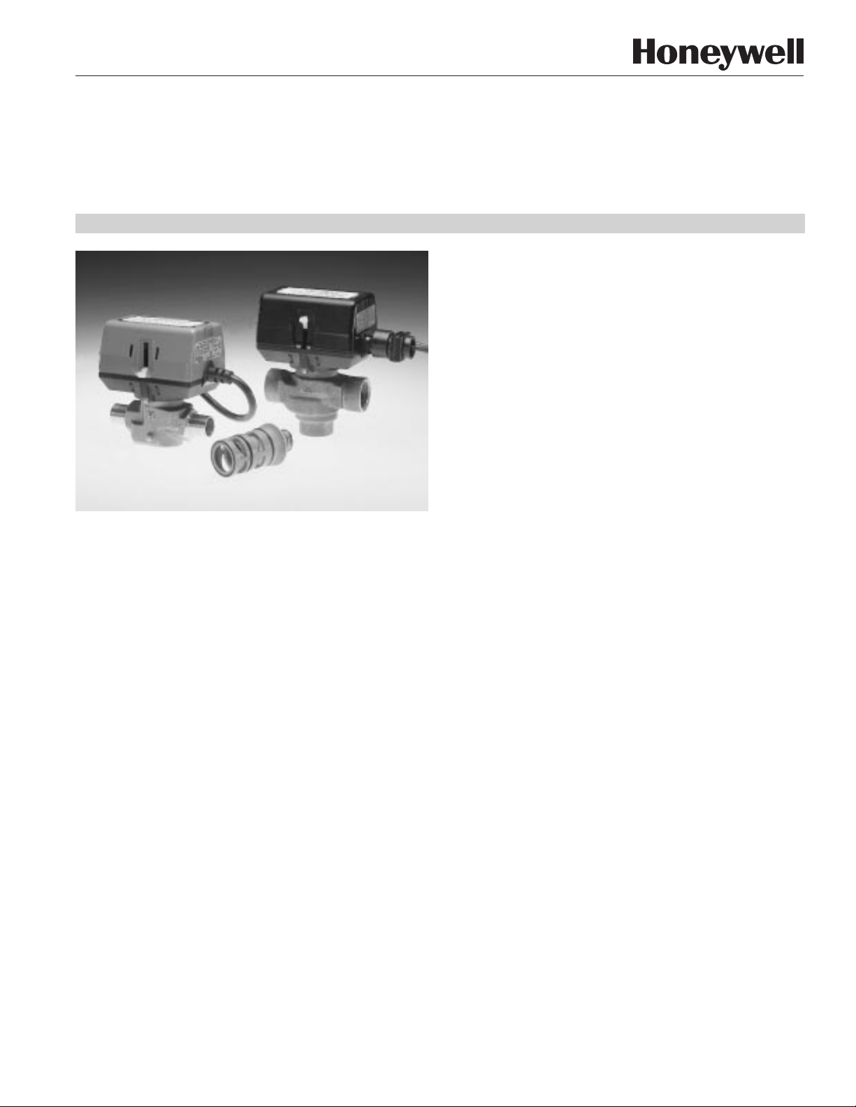
Modulating Control Valves
GENERAL
The VC7900 Series Modulating Control Valves provide
precision flow control of hot or chilled water in various heating
and cooling applications.
The VC hydronic valve consists of a valve body and
replaceable characterized cartridge assembly. When used
with a Honeywell VC7900 actuator, the valve provides
proportional flow in modulating, diverting or mixing
applications. They are designed to operate silently and resist
water hammer. These actuators have conformally coated
printed circuit boards for humidity resistance.
VC7934 actuators meet the requirements of UL94-5V fire
retardancy for mounting in return air plenums.
The VC7900 series valve actuator is used with any
0–10 Vdc or 2–10 Vdc controller.
VC7900 Series
PRODUCT DATA
FEATURES
• All actuators are interchangeable and suitable for all valves,
1/2" through 1", providing maximum installation flexibility
with minimum stock.
• Replaceable cartridge provides easy valve serviceability
without plumbing.
• High close-off pressure rating is suitable for open systems
and hydronic HVAC systems with temporary high head
pressure.
• Actuator is constructed of moisture and humidity resistant
materials.
• Motor de-energiszes when valve not in motion, extending
service life.
• Manual opener and position indicator. This "manual opener"
may be used for filling, venting, and draining the system.
• Twist-lock actuator can be installed after plumbing work has
been completed, which makes for more efficient on-site
installation. Multi-directional actuator mount allows for 4
different wiring orientations, thus providing ease of wiring
and service.
• Body dimensions are comparable to existing Honeywell
products (V4043/4044 and V8043/8044), and in most cases
can be interchanged.
• Sweat-fitted valves are supplied with the cartridge loose, to
facilitate soldering operations (an installation tool is included).
• In this balanced valve design, the internal piston moves up
and down across the water flow. The actuator provides
sinusoidal piston travel action for "soft shut-off" and open, to
eliminate water hammer in most applications.
• In 2-way valves, flow can be in either direction.
• In 3-way valves, flow can be mixing or diverting.
KT/RJ • 12/97 • © Honeywell Limited 1997 • Form Number 95C-10830-2
CONTENTS
Specifications.......................................................... 2
Ordering Information ............................................... 2
Installation ................................................................... 4
Wiring ...................................................................... 5
Operation ................................................................ 5
Service .................................................................... 6
Check-out ................................................................ 6
Page 2

VC7900 - SPECIFICATIONS, ORDERING INFORMATION
SPECIFICATIONS
Table 1. Series 70, 0/2 -10 Vdc Actuator
Nominal
Model
Series
VC7930
VC7934
Table 2. Valve Body Models,
.oN.S.O vC .oN.S.O vC
)...zCV( gnitaR eziS gnittiF )...zCV( gnitaR
xx11AA 2.3 "2/1
xx11MA 6.4 "4/3 xx16LM 9.5
xx11SA 2.6 "1 xx16SM 6.6
xx11BB 2.3 "2/1
xx11LA 7.4 "4/3 xx16KM 6.6
xx11RA 6.6 "1 xx16RM 6.8
xx11CA 1.2 "8/3
xx11DA 1.3 "2/1 xx16CM 8.3
xx11EA 2.3 "2/1 eralFdetrevnI xx16DM 2.4
xx11BA 4.3 "2/1
xx11KA 7.4 "4/3 xx16JM 2.6
xx11TA 6.6 "1 xx16TM 1.8
xx11FA 0.3 "2/1
xx11JA 2.5 "4/3 xx16HM 9.6
xx11PA 6.6 "1 xx16PM 5.7
xx11HA 2.5 "4/3
xx11QA 2.6 "1 xx16QM 9.7
xx11FA 0.3 mm51
*xx11GA 4.5 mm22 *xx16FM 9.6
*xx11NA 3.6 mm82 *xx16MM 5.7
*Includes compression nuts and olives.
For example, to order a 2 minute stroke timing actuator, with 1
meter cable and no auxiliary switch, you would order VC7931zz11.
The last two digits, "11", indicate that the actuator comes with
conformally-coated printed circuit board. To order a 3-way 3/4"
BSPP internally threaded body with characterized flow cartridge,
you would select VCzMH6100. Complete actuator and valve
assemblies may also be available in your region, for example as:
VC7931MH6111.
Voltage
(50/60 Hz)
24 Vac
24 Vac,
plenum-rated
yaW-2
Full Stroke
Timing
120 seconds
at 60 Hz
––––––––
150 seconds
at 50 Hz
with characterized flow.
elytSydoB
taewS
lanretniTPN
)TPNF(
eralF
TPSB
lanretni
PPSB
lanretni
lanretxePPSB
noisserpmoC
Electrical
Connection
6-pin Molex
1 meter cableVC7931
1 m Teflon®
cable
yaW-3
xx16AM 8.3
xx16BN 7.3
xx16BM 7.2
xx16NM 8.3
xx16EM 7.3
xx16GM 7.6
xx16EM 7.3
Supply Voltage: Label color code
24V, 50-60Hz. Class 2 circuit Blue
Control Signal:
Nominal 0/2 to 10 Vdc (actual 2 to 9 Vdc).
Input impedance 47.5 kΩ.
Power Consumption:
4 Watts Max. at nominal voltage (during valve position change).
Note: Use 24 V Class 2 transformer. Provide 6 VA for connection wire sizing.
Maximum duty cycle: 15%.
Nominal Timing:
Opens in 2 minutes @ 60Hz
Actual full stroke timing is 140 sec.
Note: Timing is approximately 20% longer @ 50Hz
Electrical Termination: 3 Versions Available:
1) Molex™ (header #39-30-1060). Requires mating connector
(receptacle/housing #39-01-2060) –
OR
2) With integral 1 meter (nominal 39") leadwire cable –
OR
3) With integral 1 meter plenum-rated leadwire cable and 3/8"
flexible conduit connector (low voltage only) –
Operating Ambient Temperature:
0 to 65 Celsius (32 to 150 degrees Fahrenheit)
Shipping and Storage Temperature:
-40 to +65 Celsius (-40 to 150 degrees Fahrenheit)
Atmosphere:
Non-condensing, non-corrosive, non-explosive.
VC7934 meets UL94-5V requirements for installation in return
air plenums.
Minimum & Maximum fluid temperatures:
1 to 95 Celsius (34 to 203 degrees Fahrenheit)
Operating Pressure Differential:
Maximum - 4 bar (60 psi)
Pressure Rating: Static - 20 Bar (300 psi)
Burst - 100 Bar (1500 psi)
Valve Material:
Body of bronze
Cartridge of Ryton™ (polyphenylene sulphide) and Noryl™
(polyphenylene oxide)
O-ring seals of EPDM rubber
Stem of stainless steel
Stem Travel: 10 mm (0.4 inches)
Flow Characteristic: Linear
The specifications above are nominal and conform to generally
accepted industry standards. Honeywell is not responsible for
damages resulting from misapplication or misuse of its products.
VC7930
VC7931
VC7934
ORDERING INFORMATION
Before ordering please determine the following:
1. The body type: 2-way or 3-way
2. The actuator voltage: 24V/50-60Hz
3. The pipe fitting, size, and flow capacity rating (Cv) required
4. Order Specification Number
5. Accessories, if desired.
If you have additional questions, need further information, or would like to comment on our products or services, please write or phone:
1. Your local Home and Building Control Sales Office (check white pages of your phone directory).
2. On the World Wide Web: www.honeywell.com/building/components
3. In U.S.A.: Honeywell, 1885 Douglas Drive North, Minneapolis, MN 55422-4386.
4. In Canada: Honeywell Limited/Honeywell Limitée, 35 Dynamic Drive, Scarborough, ON M1V 4Z9.
International Sales and Service Offices in all principal cities of the world. Manufacturing in Australia, Canada, Finland, France,
Germany, Japan, Mexico, Netherlands, Spain, Taiwan, United Kingdom, U.S.A.
2
Page 3

Accessories and Replacement Parts:
40007029-002: Wrench for removing VC cartridge
VCZZ1100: 2-way characterized cartridge, unit pack
VCZZ6100: 3-way characterized cartridge, unit pack
Fig. 1 - Nominal dimensions in inches and millimetres
VC7900
90 [3-9/16]
A
94 [3-23/32]
D
B
C
68 [2-11/16]
Table 3. 2-Way Nominal Dimensions
C D
Pipe fitting sizes
Dimensions
3/8" FLARE (no adapter) 98 3 -7/8 111 4-3/8
1/2" SWEAT 98 3 -7/8 111 4-3/8
1/2" F NPT 98 3 -7/8 111 4-3/8
1/2" FLARE (no adapter) 98 3 -7/8 111 4-3/8
1/2" INVERTED FLARE (no adapter) 98 3 -7/8 111 4-3/8
1/2" BSPP(int.), 15 mm Compression 98 3 -7/8 111 4-3/8
1/2" BSPP(int.) 98 3 -7/8 111 4-3/8
3/4" SWEAT 94 3-11/16 113 4-7/16
3/4" F NPT 94 3-11/16 113 4-7/16
3/4" BSPP (int.), 3/4" BSPT (int.) 94 3-11/16 113 4-7/16
3/4" BSPP (ext.) 94 3-11/16 113 4-7/16
22mm* Compression 112 4-7/16 113 4-7/16
1" SWEAT 94 3-11/16 113 4-7/16
1" F NPT 94 3-11/16 113 4-7/16
1" BSPP (int. & ext.) 94 3-11/16 113 4-7/16
28mm* Compression 116 4-9/16 113 4-7/16
mm Inches mm Inches
68 [2-11/16]
90 [3-9/16]
B
94 [3-23/32]
E
A
AB
C
Table 4. 3-Way Nominal Dimensions
C E
Pipe fitting sizes
Dimensions
3/8" FLARE (no adapter) 98 3 -7/8 136 5-11/32
1/2" SWEAT 98 3 -7/8 136 5-11/32
1/2" F NPT 98 3 -7/8 136 5-11/32
1/2" FLARE (no adapter) 98 3 -7/8 136 5-11/32
1/2" INVERTED FLARE (no adapter) 98 3 -7/8 136 5-11/32
1/2" BSPP(int.), 15 mm Compression 98 3 -7/8 136 5-11/32
1/2" BSPP(int.) 98 3 -7/8 136 5-11/32
3/4" SWEAT 94 3-11/16 132
3/4" F NPT 94 3-11/16 130 5-3/32
3/4" BSPP (int.), 3/4" BSPT (int.) 94 3-11/16 130 5-3/32
3/4" BSPP (ext.) 94 3-11/16 130 5-3/32
22mm* Compression 112 4-7/16 140 5-1/2
1" SWEAT 94 3-11/16 136 5-11/32
1" F NPT 94 3-11/16 136 5-11/32
1" BSPP (int. & ext.) 94 3-11/16 136 5-11/32
28mm* Compression 116 4-9/16 147 5-13/16
mm Inches mm Inches
5-3/16
*Includes compression nuts and olives
Fig. 2 - Fluid flow of 2-way valves Fig. 3 - Fluid flow of 3-way valves
AB <-> B
Closed
BA
B
Open
AB
A
B
A
AB
3
AB <-> A
95C-10830-2
Page 4

VC7900 - INSTALLATION
INSTALLATION
WHEN INSTALLING THIS PRODUCT:
1. Read these instructions carefully. Failure to follow them could
damage the product or cause a hazardous condition.
2. Check the ratings given in the instructions and on the product to
make sure the product is suitable for your application.
3. Installer must be a trained, experienced service-person.
4. Always conduct a thorough check-out when installation is
completed.
5. While not necessary to remove the actuator from the body, it can
be removed for ease of installation. The actuator can be installed
in any of the four orientations to suit the most convenient wiring
direction. Actuator latching mechanism works only when the
lengths of the actuator and the valve body are parallet to each
other.
6. An extra 25 mm head clearance is required to remove the
actuator.
CAUTION
!
1. Disconnect power supply before connecting
wiring to prevent electrical shock and equipment
damage.
2. Never jumper the supply wires or actuator terminals
even temporarily. This may damage the thermostat.
PLUMBING
The valve may be plumbed in any angle but preferably not with the
actuator below horizontal level of the body. Make sure there is
enough room around the actuator for servicing or replacement.
For use in diverting applications, the valve is installed with the flow
water entering through bottom port AB, and diverting through end
ports A or B. In mixing applications the valve is installed with inlet
to A or B and outlet through AB.
Mount the valve directly in the tube or pipe. Do not grip the actuator
while making and tightening up plumbing connections. Either hold
valve body in your hand or attach adjustable spanner (38 mm or
1-1/2") across hexagonal or flat faces on the valve body. (Figure
4).
NOTE: For trouble free operation of this product, good
installation practice includes
and the installation of
stream filter(s)
.
50 micron
initial system flushing
(or finer) system
side
COMPRESSION MODELS
For compression fitted models, tighten the compression nuts
enough to make a watertight seal. TAKE CARE NOT TO OVER
TIGHTEN. Maximum torque limit is 45 Nm (33 ft.-lb.) for the 22
mm compression fitting, and 65Nm(48 ft.-lb.) for the 28 mm
compression fitting.
SWEAT MODELS
On sweat fitted valves, the cartridge is shipped loose to avoid
being damaged during the solder operation.
1. Remove valve actuator from body and solder the connecting
pipes in accordance with normal soldering practices.
2. After soldering and valve has cooled, remove cartridge assembly
from plastic bag, insert into the valve body and tighten down with
enclosed wrench(part# 40007029-002) until it bottoms out. DO
NOT OVER TIGHTEN (maximum torque is 4.5 Nm (40 in-lb.).
The top surface of the cartridge will be flush with the top edge of
the body casting.
3. Replace valve actuator.
TO INSTALL REPLACEMENT ACTUATOR
IMPORTANT
Installation of a new actuator does not require
draining the system, provided the valve body and
valve cartridge assembly remain in the pipeline.
1. Check replacement part number and voltage ratings for
match with old device.
2. Disconnect power supply before servicing to avoid electrical
shock or equipment damage.
3. Disconnect leadwires to actuator, or depress tab on Molex
connector and remove. Where appropriate, label wires for
rewiring.
4. The actuator head is automatically latched to the valve. To
remove, press up on the latch mechanism with your thumb.
It is located directly below the white manual open lever (see
figure 5 below). Simultaneously press the actuator down
towards the body with moderate hand force and turn the
actuator counter-clockwise by 1/8 turn (45 degrees). Lift the
actuator off the valve body.
TM
Fig. 4 - Plumbing the VC Valve
Fig. 5 - Latch Mechanism to detach Actuator
4
Page 5

VC7900 - WIRING, OPERATIONS
NOTE: The actuator can also be installed at right angles to the
valve body but in this position the latch mechanism will
not engage.
5. Install the new actuator by reversing the process in (4).
6. Reconnect leadwires or Molex
TM
connector.
7. Restore power, and check-out operation.
MANUAL OPENER
The manual opener can be manipulated only when in the up
position. The "A" port can be manually opened by firmly pushing
the white manual lever down to midway and in. In this position both
the "A" and "B" ports are open, and with auxiliary switch models the
switch is closed. This "manual open" position may be used for
filling, venting and draining the system, or for opening the valve in
case of power failure. The valve can be restored manually to the
closed position by depressing the white manual lever lightly and
then pulling the lever out. The valve and actuator will return to the
automatic position when power is restored.
NOTE: If the valve is powered open, it cannot be manually
closed, unless actuator is removed.
WIRING
See figures 6a and 6b for single unit wiring details.
Multiple valves may be connected in parallel to a single controller
and transformer, up to the current rating of the controller and
transformer.
Fig.7 - VC valve actuator electrical conduit installation
3
1
2
4
Fig. 6a - Connector Pin Configuration for Molex‘ Model
and 0/2–10 Vdc Controllers (Series 70).
L1
(HOT)
+
L2
0 -
10 Vdc
24 Vac
65 4
1
32
Fig. 6b - Wiring Colour Code for Cable Models and
0/2–10 Vdc Controllers (Series 70).
Brown
L1
(HOT)
L2
10 Vdc
24 Vac
Black
+
0 -
Blue
CONDUIT CONNECTION
VC7934 may be installed as a plenum-rated cable model. Where
local codes require conduit , the conduit adapter may be used with
empty 3/8" flexible conduit to provide mechanical protection for the
wiring. All wiring connections must be made in an approved
electrical junction box. Refer to figure 7.
OPERATION
WITH SERIES 70, 0/2-10VDC CONTROLLER
(refer to figure 8)
In the VC7900, an electronic circuit compares the voltage of the
feedback potentiometer to the signal voltage. If they are different,
then the circuit closes the appropriate triac and drives the motor in
the direction that will bring the circuit back into balance. In
addition, the standard limit switches maintain the travel to the
normal operating range.
Fig. 8 - Wiring Schematic of the VC7900 Series Actuators
Brown
3
LS2
LS1
24 Vac
Black
Blue
6
Motor
Feedback
Pot
2
0 -10 Vdc
5
95C-10830-2
Page 6

VC7900 - SERVICE AND CHECK-OUT
In a direct acting model, 2 V signal will be fully closed, and 9 V will
be fully open. In a reverse acting model, 9 V is closed and 2 V is
open. However, because of the soft close off of the VC valve, initial
(and final) movements of the actuator will not cause any significant
changes in the valve stem position.
On a loss of power, the actuator will remain in the last position, and
will resume normal operation on power up. On loss of signal, a
direct acting device will go to the closed default position. A reverse
acting device will default open.
SERVICE
This valve should be serviced by a trained, experienced service
technician.
1. If the valve is leaking, drain system
system.
2. Check to see if the cartridge needs to be replaced.
3. If the motor or other internal parts of the actuator is damaged,
replace the entire actuator assembly.
NOTE: Honeywell hydronic valves are designed and tested for
Do not remove valve body from plumbing.
silent operation in properly designed and installed
systems. However, water noises may occur as a result
of excessive water velocity. Piping noises may also
occur in high temperature (over 212°F [100°C])
systems with insufficient water pressure.
OR
isolate valve from the
IMPORTANT
Do not use boiler additives which are petroleum based
or contain mineral oil, hydrocarbons, or ethylene glycol
acetate. Compounds which can be used, with
minimum 50% water dilution, are diethylene glycol,
ethylene glycol, and propylene glycol(anti-freeze
solutions).
CHECK-OUT
1. Raise the set point of the thermostat above room temperature to
initiate a call for heat.
2. Observe all control devices - 2 way valve should open. Port A in
3 way valve should open, and port B should close.
3. Lower the set point of the thermostat below room temperature.
4. Observe the control devices. 2 way valve should close. Port A
in 3 way valve should close, and port B should open.
Home and Building Control In Canada:
Honeywell Inc. Honeywell Limited–Limitée
1985 Douglas Drive North 155 Gordon Baker Road
Golden Valley, MN 55422 North York, ON M2H 3N7
Printed in Canada www.honeywell.com/building/components
Helping You Control Your World
 Loading...