

Honeywell VA8201 Installation And Setup Manual
ADEMCO VA8201
Alpha Pager Module
INSTALLATION AND SETUP GUIDE
K5443V1 10/04 Rev. A
GENERAL INFORMATION
The ADEMCO VA8201 Alpha Pager Module (APM)
provides:
• Communication between the control panel and an alpha
paging service center.
• Data transfer to a parallel printer via the APM’s
parallel output.
• Data transfer to PCs with IBM Home Automation
Protocol or a serial printer via the APM’s serial output.
NOTE: The paging feature of the VA8201 may not work
with all alpha paging service centers. Data transfer
features between the control and printers will still function
even if the paging feature does not.
The APM transmits alphanumeric messages to the paging
service using Telocator Alphanumeric Protocol (TAP). The
installer should check with the paging service to ensure
they are using TAP protocol Rev. 1.8.
The types of messages that can be transmitted are security
control panel dependent. The APM sends alphanumeric
messages to the paging service when a programmed security
control panel initiates an event report.
Refer to the Ademco Security Control Panel Installation and
Setup Guide for the types of messages available and for
event report programming.
INSTALLING THE VA8201 APM
The VA8201 APM is installed sharing the same telephone
line as the security system control panel. In this
configuration, conditions that are programmed to report to
both the central station and the alpha pager will report to
the central station first. When a parallel printer is
connected to the parallel printer output of the APM, the
security system control sends its event data to the printer
before it sends the APM messages to the pager service or
the Home Automation Computer.
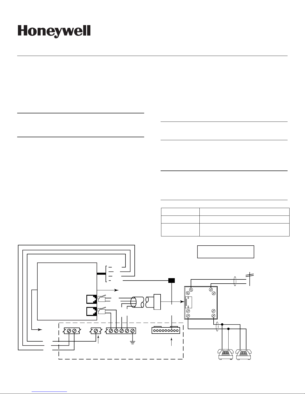
MOUNTING AND WIRING THE VA8201 APM
Mount the VA8201 APM next to the security system control
panel using bracket interface Ademco Part Number K5350.
Wire the VA8201 APM’s four flying leads (DATA/POWER)
and TELCO connections (TO LINE and TO PHONE) to
security system control and premises handsets. Wire the
VA8201 APM in accordance with Figure 1. Use appropriate
ADEMCO accessories (or equivalent) to make system
connections.
NOTE: To comply with FCC Class B (Residential)
requirements, the VA8201 APM must be mounted in a
grounded metal enclosure.
PROGRAMMING
Refer to the Programming section of the Installation and
Setup Guide for your control on how to program phone
numbers, Alarms, and Trouble Reports when using the
Alpha Pager Module.
NOTE: Prior to programming the VISTA control for use
with the APM and paging device(s), verify the correct access
and PIN number to be used with each receiving device.
Entering an incorrect access or PIN number will render the
pager inoperable for alarm panel reporting.
SPECIFICATIONS
Dimensions: 6-1/4” L x 6-1/8” W x 1-13/16” H.
Voltage: 12 Volts DC
Current: 63mA (standby mode), 165mA (active
mode)
NOTE
WHEN USING THE VA8201, ZONE 9 CAN NO
LONGER BE USED AS A PROTECTION ZONE.
VA8201 ALPHA PAGER MODULE
DATA /
POWER
PARALLEL
OUTPUT
PARALLEL
PRINTER
GREEN
RED
BLACK
AUX
PWR.
62627282930237
TO PHONE
RJ11
TO LINE
RJ11
AUX
GND.
SERIAL
OUTPUT
(ZONE 9)
Figure 1. VA8201 Alpha Pager Module Summary of Connections
GREEN
RED
BLACK
ORANGE
HOME AUTOMATION COMPUTER
GRAY
BROWN
RED
GREEN
TIP RING
TIP RING
HANDSET
INCOMING
EARTH
GROUND
CONTROL PANEL
620
PHONE
CORD
J8
SPLICE
BROWN
1 2 3 4 5 6 7 8 9
BROWN WIRE
FROM 4142 TR
TRIGGER CABLE
INCOMING
PHONE LINE
RED
45
3
RJ31X
2
1
PREMISES
PHONES
6
7
8
TO
GREEN
RING
TIP
TIP
RING
GREY
BROWN
VA8201-SOC-V1

“FEDERAL COMMUNICATIONS COMMISSION (FCC) Part 68 NOTICE”
This equipment complies with Part 68 of the FCC rules. On the front cover of this equipment is a label that contains, among other information,
the FCC registration number and ringer equivalence number (REN) for this equipment. If requested, this information must be provided to the
telephone company.
This equipment uses the following jacks:
An RJ11 is used to connect this equipment to the telephone network.
The REN is used to determine the quantity of devices which may be connected to the telephone line. Excessive RENs on the telephone line may
result in the devices not ringing in response to an incoming call. In most, but not all areas, the sum of the RENs should not exceed five (5.0). To
be certain of the number of devices that may be connected to the line, as determined by the total RENs, contact the telephone company to
determine the maximum REN for the calling area.
If this equipment causes harm to the telephone network, the telephone company will notify you in advance that temporary discontinuance of
service may be required. If advance notice is not practical, the telephone company will notify the customer as soon as possible. Also, you will be
advised of your right to file a complaint with the FCC if you believe it to be necessary.
The telephone company may make changes in its facilities, equipment, operations, or procedures that could affect the operation of the equipment.
If this happens, the telephone company will provide advance notice in order for you to make the necessary modifications in order to maintain
uninterrupted service.
If trouble is experienced with this equipment, please contact the manufacturer for repair and warranty information. If the trouble is causing
harm to the telephone network, the telephone company may request you remove the equipment from the network until the problem is resolved.
There are no user serviceable components in this product, and all necessary repairs must be made by the manufacturer. Other repair methods
may invalidate the FCC registration on this product.
This equipment cannot be used on telephone company-provided coin service. Connection to Party Line Service is subject to state tariffs.
This equipment is hearing-aid compatible.
When programming or making test calls to an emergency number, briefly explain to the dispatcher the reason for the call. Perform such activities
in the off-peak hours; such as early morning or late evening.
“FEDERAL COMMUNICATIONS COMMISSION (FCC) Part 15 STATEMENT”
This equipment has been tested and found to comply with the limits for a Class A digital device, pursuant to Part 15 of the FCC Rules. These
limits are designed to provide reasonable protection against harmful interference when the equipment is operated in a commercial environment.
This equipment generates, uses, and can radiate radio frequency energy; and, if not installed and used in accordance with the instruction
manual, may cause harmful interference to radio communications. Operation of this equipment in a residential area is likely to cause harmful
interference in which case the user will be required to correct the interference at his own expense.
FOR WARRANTY INFORMATION, AND LIMITATIONS OF THE ENTIRE ALARM SYSTEM, REFER TO THE INSTALLATION
INSTRUCTIONS FOR THE CONTROL WITH WHICH THIS DEVICE IS USED.
ÊK5443V1KŠ
K5443V1 10/04 Rev.A
165 Eileen Way, Syosset, New York 11791
Copyright © 2004 Honeywell International Inc.
www.honeywell.com/security
 Loading...